JP2017017289A - Drum-type core, coil component and manufacturing method thereof - Google Patents
Drum-type core, coil component and manufacturing method thereof Download PDFInfo
- Publication number
- JP2017017289A JP2017017289A JP2015135492A JP2015135492A JP2017017289A JP 2017017289 A JP2017017289 A JP 2017017289A JP 2015135492 A JP2015135492 A JP 2015135492A JP 2015135492 A JP2015135492 A JP 2015135492A JP 2017017289 A JP2017017289 A JP 2017017289A
- Authority
- JP
- Japan
- Prior art keywords
- corner
- core
- coil component
- pair
- drum
- Prior art date
- Legal status (The legal status is an assumption and is not a legal conclusion. Google has not performed a legal analysis and makes no representation as to the accuracy of the status listed.)
- Granted
Links
Images


Landscapes
- Manufacturing Cores, Coils, And Magnets (AREA)
- Coils Or Transformers For Communication (AREA)
Abstract
【課題】巻芯部にワイヤを巻回する際のワイヤの破損を防止する。【解決手段】巻芯部11の断面は、Z方向に延在する辺L1,L2と、辺L1の一端及び他端にそれぞれ位置する角部E1,E2と、辺L2の一端及び他端にそれぞれ位置する角部E3,E4と、角部E1と角部E3との間に位置する辺L3と、角部E2と角部E4との間に位置する辺L4とを含む。辺L1と辺L3が成す角は、辺L1と辺L4が成す角よりも小さく、辺L2と辺L3が成す角は、辺L2と辺L4が成す角よりも大きい。本発明によれば、角部E1,E2,E4,E3の順に接するよう、ワイヤを巻芯部に巻回すれば、ワイヤにかかる負担が従来よりも軽減される。これにより、ワイヤの損傷を防止することが可能となる。【選択図】図2An object of the present invention is to prevent breakage of a wire when the wire is wound around a winding core. A cross section of a winding core part 11 includes sides L1 and L2 extending in the Z direction, corners E1 and E2 positioned at one end and the other end of the side L1, respectively, and one end and the other end of the side L2. Each includes corners E3 and E4 positioned, a side L3 positioned between the corners E1 and E3, and a side L4 positioned between the corners E2 and E4. The angle formed by the side L1 and the side L3 is smaller than the angle formed by the side L1 and the side L4, and the angle formed by the side L2 and the side L3 is larger than the angle formed by the side L2 and the side L4. According to the present invention, if the wire is wound around the core portion so as to contact the corner portions E1, E2, E4, and E3 in this order, the burden on the wire is reduced as compared with the related art. This makes it possible to prevent damage to the wire. [Selection] Figure 2
Description
本発明はドラム型コア、コイル部品及びその製造方法に関し、特に、ドラム型コア及びこれを用いたコイル部品並びにその製造方法に関する。 The present invention relates to a drum core, a coil component, and a manufacturing method thereof, and more particularly, to a drum core, a coil component using the drum core, and a manufacturing method thereof.
近年、スマートフォンなどの情報端末に用いられる電子部品に対しては、小型化及び低背化が強く求められている。このため、コモンモードフィルタやパルストランスなどのコイル部品についても、トロイダル型コアではなく、ドラム型コアを用いた表面実装型のコイル部品が数多く使用されている。例えば、特許文献1には種々の形状を有するドラム型コアが例示されている。
In recent years, electronic components used in information terminals such as smartphones have been strongly demanded to be downsized and reduced in height. For this reason, as for coil parts such as common mode filters and pulse transformers, many surface mount type coil parts using a drum type core are used instead of a toroidal type core. For example,
しかしながら、特許文献1に記載されたドラム型コアは、プレス加工によって成形する際、端部が尖った形状を有する金型を用いる必要がある(特許文献1の第2図参照)。このため、金型の端部において強度が不足し、この部分において金型が破損してしまうという問題が生じる。
However, when the drum core described in
このような問題を解決するためには、特許文献2に記載されているように、金型の端部に平坦なプレス受面を設けることが有効である。 In order to solve such a problem, as described in Patent Document 2, it is effective to provide a flat press receiving surface at the end of the mold.
しかしながら、金型の端部に平坦なプレス受面を設けると、ドラム型コアの巻芯部に約90°の角部が形成される。このような角部は、巻芯部の軸方向に沿って4箇所形成されるため、巻芯部にワイヤを巻回する際に、角部によってワイヤが損傷するおそれがあった。 However, when a flat press receiving surface is provided at the end of the mold, a corner of about 90 ° is formed at the core of the drum core. Since such corner portions are formed at four locations along the axial direction of the core portion, the wire may be damaged by the corner portions when the wire is wound around the core portion.
したがって、本発明は、ワイヤの損傷を防止することが可能なドラム型コア及びこれを用いたコイル部品並びにその製造方法を提供することを目的とする。 Accordingly, an object of the present invention is to provide a drum core capable of preventing damage to a wire, a coil component using the drum core, and a manufacturing method thereof.
本発明の一側面によるコイル部品は、一対の鍔部と、前記一対の鍔部間に位置する巻芯部とを含むドラム型コアと、前記巻芯部に巻回されたワイヤとを備え、前記巻芯部の軸方向と交差する断面は、互いに平行な第1及び第2の辺と、前記第1の辺の一端及び他端にそれぞれ位置する第1及び第2の角部と、前記第2の辺の一端及び他端にそれぞれ位置する第3及び第4の角部と、前記第1の角部と前記第3の角部との間に位置する第3の辺と、前記第2の角部と前記第4の角部との間に位置する第4の辺とを含み、前記第3の辺と前記第4の辺は互いに対向しており、前記第1の辺と前記第3の辺が成す第1の角は、前記第1の辺と前記第4の辺が成す第2の角よりも小さく、前記第2の辺と前記第3の辺が成す第3の角は、前記第2の辺と前記第4の辺が成す第4の角よりも大きいことを特徴とする。 A coil component according to an aspect of the present invention includes a pair of flange portions, a drum core including a core portion located between the pair of flange portions, and a wire wound around the core portion, The cross section intersecting with the axial direction of the core part includes first and second sides parallel to each other, first and second corners located at one end and the other end of the first side, A third side and a fourth corner located at one end and the other end of the second side, respectively, a third side located between the first corner and the third corner, 2 corners and a fourth side located between the fourth corners, the third side and the fourth side are opposed to each other, the first side and the fourth side The first corner formed by the third side is smaller than the second corner formed by the first side and the fourth side, and the third corner formed by the second side and the third side. Is the second side Being larger than the fourth angle formed the fourth sides.
本発明の一側面によるドラム型コアは、一対の鍔部と、前記一対の鍔部間に位置する巻芯部とを含むドラム型コアであって、前記巻芯部の軸方向と交差する断面は、互いに平行な第1及び第2の辺と、前記第1の辺の一端及び他端にそれぞれ位置する第1及び第2の角部と、前記第2の辺の一端及び他端にそれぞれ位置する第3及び第4の角部と、前記第1の角部と前記第3の角部との間に位置する第3の辺と、前記第2の角部と前記第4の角部との間に位置する第4の辺とを含み、前記第3の辺と前記第4の辺は互いに対向しており、前記第1の辺と前記第3の辺が成す第1の角は、前記第1の辺と前記第4の辺が成す第2の角よりも小さく、前記第2の辺と前記第3の辺が成す第3の角は、前記第2の辺と前記第4の辺が成す第4の角よりも大きいことを特徴とする。 A drum-type core according to one aspect of the present invention is a drum-type core including a pair of flange portions and a core portion positioned between the pair of flange portions, and a cross section that intersects the axial direction of the core portion. Are respectively parallel to each other, the first and second corners located at one end and the other end of the first side, respectively, and the one end and the other end of the second side, respectively. Third and fourth corners located, a third side located between the first corner and the third corner, the second corner and the fourth corner And the third side and the fourth side are opposed to each other, and the first angle formed by the first side and the third side is , Smaller than a second angle formed by the first side and the fourth side, and a third angle formed by the second side and the third side is defined by the second side and the fourth side. The fourth corner formed by Characterized in that also large.
本発明によれば、第1の角部、第2の角部、第4の角部及び第3の角部の順に接するよう、ワイヤを巻芯部に巻回すれば、ワイヤにかかる負担が従来よりも軽減される。これにより、ワイヤの損傷を防止することが可能となる。 According to the present invention, if the wire is wound around the core portion so as to contact the first corner portion, the second corner portion, the fourth corner portion, and the third corner portion in this order, the load on the wire is reduced. It is reduced than before. This makes it possible to prevent damage to the wire.
本発明において、前記第1乃至第4の角部の角度はいずれも約90°であることが好ましい。これによれば、ドラム型コアの成形に使用する金型の強度を高めることが可能となる。 In the present invention, it is preferable that the angles of the first to fourth corners are about 90 °. According to this, it becomes possible to raise the intensity | strength of the metal mold | die used for shaping | molding of a drum type core.
本発明において、前記第1及び第4の角はいずれも90°未満であり、前記第2及び第3の角はいずれも90°超であることが好ましい。これによれば、巻回時においてワイヤにかかる負担を効果的に軽減することが可能となる。 In the present invention, it is preferable that both the first and fourth angles are less than 90 °, and both the second and third angles are more than 90 °. According to this, it is possible to effectively reduce the burden on the wire during winding.
本発明において、前記断面は、前記第3の辺の一端と前記第1の角部を接続する第1の接続辺と、前記第4の辺の一端と前記第2の角部を接続する第2の接続辺と、前記第3の辺の他端と前記第3の角部を接続する第3の接続辺と、前記第4の辺の他端と前記第4の角部を接続する第4の接続辺と、をさらに含むことが好ましい。この場合、前記第3の辺と前記第4の辺は互いに平行であっても構わないし、いずれも凸型に湾曲していても構わない。 In the present invention, the cross section includes a first connecting side connecting one end of the third side and the first corner, and a first connecting side connecting the one end of the fourth side and the second corner. 2 connecting sides, a third connecting side connecting the other end of the third side and the third corner, and a second connecting side connecting the other end of the fourth side and the fourth corner. It is preferable that four connection sides are further included. In this case, the third side and the fourth side may be parallel to each other, or both may be curved in a convex shape.
本発明の他の側面によるコイル部品は、一対の鍔部と、前記一対の鍔部間に位置する巻芯部とを含むドラム型コアと、前記巻芯部に巻回されたワイヤとを備え、前記巻芯部は、互いに平行な第1及び第2の面と、前記第1の面の互いに対向する二辺にそれぞれ位置する第1及び第2の角部と、前記第2の面の互いに対向する二辺にそれぞれ位置する第3及び第4の角部とを含み、前記一対の鍔部の前記軸方向と平行な所定面を基準として、前記第1の角部は前記第3の角部よりも高い位置にあり、且つ、前記第2の角部は前記第4の角部よりも高い位置にあることを特徴とする。 A coil component according to another aspect of the present invention includes a drum core including a pair of flange portions, a core portion positioned between the pair of flange portions, and a wire wound around the core portion. The winding core portion includes first and second surfaces parallel to each other, first and second corner portions positioned on two opposite sides of the first surface, and the second surface. The first corner portion includes the third and fourth corner portions positioned on two opposite sides, respectively, and the first corner portion is defined by the third plane with reference to a predetermined plane parallel to the axial direction of the pair of flange portions. The second corner is located higher than the corner, and the second corner is located higher than the fourth corner.
本発明の他の側面によるドラム型コアは、一対の鍔部と、前記一対の鍔部間に位置する巻芯部とを含むドラム型コアであって、前記巻芯部は、互いに平行な第1及び第2の面と、前記第1の面の互いに対向する二辺にそれぞれ位置する第1及び第2の角部と、前記第2の面の互いに対向する二辺にそれぞれ位置する第3及び第4の角部とを含み、前記一対の鍔部の前記軸方向と平行な所定面を基準として、前記第1の角部は前記第3の角部よりも高い位置にあり、且つ、前記第2の角部は前記第4の角部よりも高い位置にあることを特徴とする。 A drum core according to another aspect of the present invention is a drum core including a pair of flange portions and a core portion positioned between the pair of flange portions, the core portions being parallel to each other. 1st and 2nd surface, 1st and 2nd corner | angular part located in two mutually opposing sides of said 1st surface, respectively, 3rd each located in two mutually opposing sides of said 2nd surface And the fourth corner, the first corner is at a position higher than the third corner with reference to a predetermined plane parallel to the axial direction of the pair of flanges, and The second corner is located higher than the fourth corner.
本発明においても、第1の角部、第2の角部、第4の角部及び第3の角部の順に接するよう、ワイヤを巻芯部に巻回すれば、ワイヤにかかる負担が従来よりも軽減される。これにより、ワイヤの損傷を防止することが可能となる。 Also in the present invention, if the wire is wound around the core portion so as to contact the first corner portion, the second corner portion, the fourth corner portion, and the third corner portion in this order, the burden on the wire is conventionally increased. Is alleviated. This makes it possible to prevent damage to the wire.
本発明において、前記第1及び第2の面は、前記所定面に対して垂直であることが好ましい。これによれば、金型を用いたドラム型コアの成形が容易となる。この場合、コイル部品は、前記一対の鍔部の前記所定面に形成された端子電極をさらに備え、前記ワイヤの端部は前記端子電極に継線されていることが好ましい。 In the present invention, it is preferable that the first and second surfaces are perpendicular to the predetermined surface. According to this, it becomes easy to mold the drum core using the mold. In this case, it is preferable that the coil component further includes a terminal electrode formed on the predetermined surface of the pair of flange portions, and an end portion of the wire is connected to the terminal electrode.
本発明において、前記巻芯部は、前記第1の角部と前記第3の角部との間に位置する第3の面と、前記第2の角部と前記第4の角部との間に位置する第4の面と、をさらに含み、前記第3及び第4の面は、前記所定面に対して所定の傾きを有していることが好ましい。これによれば、断面が略長方形である巻芯部を用いた場合とほぼ同じ磁気特性を得ることが可能となる。 In the present invention, the winding core portion includes a third surface positioned between the first corner portion and the third corner portion, and the second corner portion and the fourth corner portion. It is preferable that the third and fourth surfaces further have a predetermined inclination with respect to the predetermined surface. According to this, it is possible to obtain substantially the same magnetic characteristics as in the case of using a core part having a substantially rectangular cross section.
本発明によれば、ワイヤの損傷を防止することが可能なコイル部品及びその製造方法を提供することが可能となる。 ADVANTAGE OF THE INVENTION According to this invention, it becomes possible to provide the coil components which can prevent damage to a wire, and its manufacturing method.
以下、図面を参照しながら、本発明の好ましい実施形態について詳細に説明する。 Hereinafter, preferred embodiments of the present invention will be described in detail with reference to the drawings.
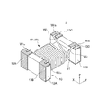
図1は、本発明の実施形態によるコイル部品1の外観構造を示す略斜視図である。
FIG. 1 is a schematic perspective view showing an external structure of a
本実施形態によるコイル部品1は表面実装型のコモンモードフィルタであり、図1に示すように、ドラム型コア10と、2本のワイヤW1,W2とを備えている。但し、本発明によるコイル部品がコモンモードフィルタに限定されるものではなく、パルストランス、バルントランスなどのトランス部品であっても構わない。
The
ドラム型コア10は、棒状の巻芯部11と、巻芯部11の両端に設けられた鍔部12A,12Bとが一体化された構成を有しており、ワイヤW1,W2はドラム型コア10の巻芯部11に巻回されている。巻芯部11の軸方向はY方向であり、Y方向における両端に鍔部12A,12Bが設けられている。ドラム型コア10は、比較的透磁率の高い磁性材料、例えばNi−Zn系フェライトや、Mn−Zn系フェライトの焼結体によって構成されている。後述するように、ドラム型コア10は金型を用いたプレス加工によって成形される。
The
一方の鍔部12Aには一対の端子電極13A,13Bが設けられており、他方の鍔部12Bには一対の端子電極13C,13Dが設けられている。特に限定されるものではないが、端子電極13A〜13Dは、いずれも鍔部12A又は12Bの上面、外側面及び底面にかけて連続的に形成された3面電極構造を有している。コイル部品1をプリント基板に実装する場合、鍔部12A,12Bの上面又は底面が実装面となり、外側面にハンダのフィレットが形成される。
A pair of
ワイヤW1,W2は被覆導線であり、互いに磁気結合する一対のコイルを構成している。ワイヤW1,W2は互いに同一方向に巻回されており、ターン数も実質的に同一である。ワイヤW1,W2の端部は、対応する端子電極に接続されている。具体的には、ワイヤW1の一端W1aは端子電極13Aに継線され、ワイヤW1の他端W1bは端子電極13Cに継線される。また、ワイヤW2の一端W2aは端子電極13Bに継線され、ワイヤW2の他端W2bは端子電極13Dに継線される。
The wires W1 and W2 are coated conductors and constitute a pair of coils that are magnetically coupled to each other. The wires W1 and W2 are wound in the same direction, and the number of turns is substantially the same. The ends of the wires W1, W2 are connected to corresponding terminal electrodes. Specifically, one end W1a of the wire W1 is connected to the
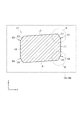
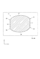
図2は、ドラム型コア10の巻芯部11の断面形状を示す図である。
FIG. 2 is a diagram illustrating a cross-sectional shape of the
図2に示す断面は、巻芯部11の軸方向に垂直な断面、つまりXZ断面であり、その形状を理解しやすくするため、Y方向から見た鍔部12A,12Bの形状も破線で示されている。図2に示すように、鍔部12A,12Bの上面及び底面はXY平面と平行であり、鍔部12A,12Bの側面はYZ平面と平行である。したがって、Y方向から見た鍔部12A,12Bの形状は長方形(又は正方形)である。
The cross section shown in FIG. 2 is a cross section perpendicular to the axial direction of the core 11, that is, an XZ cross section. Has been. As shown in FIG. 2, the upper and bottom surfaces of the
これに対し、巻芯部11の断面は略平行四辺形であり、特に、対向する辺L3,L4がX方向と平行ではなく、所定の傾きを有している。つまり、巻芯部11を構成する面のうち、辺L3,L4に対応する面(図1における上面及び下面)がXY平面と平行ではなく、所定の傾きを有している。尚、図2に示す例では、辺L3と辺L4は互いに平行である。
On the other hand, the cross section of the
一方、対向する辺L1,L2はZ方向と平行である。つまり、巻芯部11を構成する面のうち、辺L1,L2に対応する面(図1における右側面及び左側面)がYZ面と平行である。
On the other hand, the opposing sides L1 and L2 are parallel to the Z direction. That is, among the surfaces constituting the
また、辺L1と辺L3の間には接続辺C1が存在し、辺L1と辺L4の間には接続辺C2が存在し、辺L2と辺L3の間には接続辺C3が存在し、辺L2と辺L4の間には接続辺C4が存在する。これら接続辺C1〜C4は、辺L3又は辺L4に対して約60°程度の角度を有している。このような接続辺C1〜C4を設けているのは、巻芯部11の断面を多角形とすることによって巻回時におけるワイヤW1,W2の曲げ角度を緩和し、これによりワイヤW1,W2の破損を防止するためである。
Further, a connecting side C1 exists between the side L1 and the side L3, a connecting side C2 exists between the side L1 and the side L4, and a connecting side C3 exists between the side L2 and the side L3. A connection side C4 exists between the side L2 and the side L4. These connection sides C1 to C4 have an angle of about 60 ° with respect to the side L3 or the side L4. Such connection sides C1 to C4 are provided by relaxing the bending angle of the wires W1 and W2 at the time of winding by making the cross section of the winding
さらに、辺L1の両端にはそれぞれ角部E1,E2が存在し、辺L2の両端にはそれぞれ角部E3,E4が存在する。したがって、接続辺C1は辺L3の一端と角部E1を接続し、接続辺C2は辺L4の一端と角部E2を接続し、接続辺C3は辺L3の他端と角部E3を接続し、接続辺C4は辺L4の他端と角部E4を接続する。角部E1〜E4は、巻芯部11の軸方向(Y方向)に沿って延在し、立体的に見れば、辺L1,L2に対応する面(図1における右側面及び左側面)の対向する二辺(上辺及び下辺)に位置する。そして、鍔部12A,12Bの所定面、例えば底面を基準とすると、角部E1は角部E3よりも高い位置にあり、角部E2は角部E4よりも高い位置にある。
Further, corners E1 and E2 exist at both ends of the side L1, and corners E3 and E4 exist at both ends of the side L2, respectively. Therefore, the connection side C1 connects one end of the side L3 and the corner E1, the connection side C2 connects one end of the side L4 and the corner E2, and the connection side C3 connects the other end of the side L3 and the corner E3. The connection side C4 connects the other end of the side L4 and the corner E4. The corners E1 to E4 extend along the axial direction (Y direction) of the
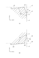
図3(a)は図2に示す領域Aを拡大して示す図であり、図3(b)は図2に示す領域Bを拡大して示す図である。 3A is an enlarged view of the area A shown in FIG. 2, and FIG. 3B is an enlarged view of the area B shown in FIG.
図3(a),(b)には、補助線x1〜x4及び補助線z1が示されている。補助線x1〜x4はいずれもX方向に延在し、このうち、補助線x1は辺L1の一端に位置し、補助線x2は辺L1の他端に位置し、補助線x3は辺L3と接続辺C1の角に位置し、補助線x4は辺L4と接続辺C2の角に位置する。一方、補助線z1はZ方向に延在し、辺L1に沿っている。 3A and 3B show the auxiliary lines x1 to x4 and the auxiliary line z1. The auxiliary lines x1 to x4 all extend in the X direction. Among these, the auxiliary line x1 is located at one end of the side L1, the auxiliary line x2 is located at the other end of the side L1, and the auxiliary line x3 is connected to the side L3. Located at the corner of the connecting side C1, the auxiliary line x4 is located at the corner of the side L4 and the connecting side C2. On the other hand, the auxiliary line z1 extends in the Z direction and extends along the side L1.
このような補助線を用いて説明すると、辺L1は補助線z1に沿っており、その一端は補助線x1の位置にて終端し、他端は補助線x2の位置にて終端する。辺L1の一端には角部E1が設けられ、辺L1の他端には角部E2が設けられる。角部E1は、辺L1と辺e1の交点によって構成され、辺e1が補助線x1に沿っていることから、角部E1の角度は約90°である。同様に、角部E2は、辺L1と辺e2の交点によって構成され、辺e2が補助線x2に沿っていることから、角部E2の角度は約90°である。但し、角部の角度が厳密に90°である必要はない。 If it demonstrates using such an auxiliary | assistant line, the edge | side L1 will be along the auxiliary | assistant line z1, the one end will be terminated at the position of the auxiliary line x1, and the other end will be terminated at the position of the auxiliary line x2. A corner E1 is provided at one end of the side L1, and a corner E2 is provided at the other end of the side L1. The corner E1 is formed by the intersection of the side L1 and the side e1, and the side e1 is along the auxiliary line x1, so the angle of the corner E1 is about 90 °. Similarly, the corner E2 is formed by the intersection of the side L1 and the side e2, and the side e2 is along the auxiliary line x2. Therefore, the angle of the corner E2 is about 90 °. However, the angle of the corner portion does not need to be strictly 90 °.
辺e1は接続辺C1の一端に接続され、接続辺C1の他端は辺L3の一端に接続される。同様に、辺e2は接続辺C2の一端に接続され、接続辺C2の他端は辺L4の一端に接続される。辺L3は補助線x3に対して右上がり(左下がり)に所定の傾きを有しており、辺L4は補助線x4に対して右上がり(左下がり)に所定の傾きを有している。 The side e1 is connected to one end of the connection side C1, and the other end of the connection side C1 is connected to one end of the side L3. Similarly, the side e2 is connected to one end of the connection side C2, and the other end of the connection side C2 is connected to one end of the side L4. The side L3 has a predetermined inclination that rises right (downward to the left) with respect to the auxiliary line x3, and the side L4 has a predetermined inclination that rises right (downward to the left) with respect to the auxiliary line x4.
ここで、上記の傾きをαとすると、辺L1と辺L3が成す角θaは90°−αであり、辺L1と辺L4が成す角θbは90°+αである。つまり、角θaと角θbとの関係は、
θa<θb
であり、且つ
θa+θb≒180°
である。
Here, if the above inclination is α, the angle θa formed by the side L1 and the side L3 is 90 ° −α, and the angle θb formed by the side L1 and the side L4 is 90 ° + α. That is, the relationship between the angle θa and the angle θb is
θa <θb
And θa + θb≈180 °
It is.
図示しないが、角部E3近傍の形状については、図3(b)に示す形状を180°反転した他は同様であり、角部E4近傍の形状については、図3(a)に示す形状を180°反転した他は同様である。 Although not shown, the shape near the corner E3 is the same except that the shape shown in FIG. 3B is inverted by 180 °, and the shape near the corner E4 is the shape shown in FIG. It is the same except that it is inverted 180 °.
次に、上述した角部E1〜E4が形成される理由について説明する。 Next, the reason why the corners E1 to E4 are formed will be described.
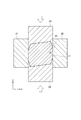
図4は、プレス加工時における巻芯部11のXZ断面を示す図である。
FIG. 4 is a view showing an XZ cross section of the
ドラム型コア10の成形は、金型を用いたプレス加工によって行われる。図4に示すように、金型としては、YZ平面を画定する2つの型枠21,22と、Z方向にプレスする上型23及び下型24が用いられる。上型23及び下型24には、接続辺C1〜C4を形成するためのテーパー部25が設けられているが、テーパー部25がそのまま型枠21,22に接すると、この部分において上型23及び下型24の強度が不足し、破損してしまう。
The
このような問題を防止すべく、テーパー部25の先端を尖らせるのではなく、テーパー部25の先端にプレス受面である平坦部26を設けている。平坦部26は、XY平面と平行な面であるため、Z方向にかかるプレス圧力を垂直に平面で受けることができる。このような平坦部26を設けることにより、上型23及び下型24の強度が確保されている。
In order to prevent such a problem, the
但し、平坦部26を設けると、当然ながらその形状が巻芯部11に反映され、角部E1〜E4が形成される。つまり、平坦部26によって、巻芯部11には図3に示す辺e1,e2が形成され、これにより角部E1〜E4が形成される。角部E1〜E4は約90°の角度を有しているため、ワイヤW1,W2の巻回時にストレスがかかり、この部分においてワイヤの破損が生じやすくなる。
However, when the
しかしながら、本実施形態においては、ドラム型コア10の巻芯部11が上述した形状を有していることから、巻回時においてワイヤW1,W2にかかるストレスが軽減され、破損が防止される。以下、その理由について説明する。
However, in this embodiment, since the
図5は、巻芯部11に対するワイヤW1,W2の巻回方向を説明するための図である。
FIG. 5 is a view for explaining the winding direction of the wires W1 and W2 with respect to the winding
図5に示すように、本実施形態においては、図5に示す断面を有する巻芯部11に対し、ワイヤW1,W2を時計回り(右回り)に巻回する。これにより、ワイヤW1,W2が角部E1〜E4に接触する際のストレスが軽減される。
As shown in FIG. 5, in this embodiment, the wires W <b> 1 and W <b> 2 are wound clockwise (clockwise) around the
まず、ワイヤW1,W2が角部E1に接触するケースを考えると、ワイヤW1,W2は、辺L3と接続辺C1の角で折り曲げられ、辺L1に接近する。ワイヤW1,W2をさらに折り曲げると、やがてワイヤW1,W2は角部E1に接触し、その後、辺L1に接触する。この時、辺L1と辺L3が成す角θaが90°−α、つまり鋭角であることから、ワイヤW1,W2が角部E1に接触した後は、それほど強く折り曲げることなくワイヤW1,W2が辺L1に接触する。このため、角部E1によるワイヤW1,W2へのストレスは小さい。 First, considering the case where the wires W1 and W2 are in contact with the corner E1, the wires W1 and W2 are bent at the corners of the side L3 and the connection side C1, and approach the side L1. When the wires W1, W2 are further bent, the wires W1, W2 eventually come into contact with the corner portion E1, and then come into contact with the side L1. At this time, since the angle θa formed by the side L1 and the side L3 is 90 ° −α, that is, an acute angle, the wires W1 and W2 are not bent so much after the wires W1 and W2 are in contact with the corner E1. Contact L1. For this reason, the stress to the wires W1, W2 by the corner E1 is small.
これに対し、図6に示す参考例のように、辺L1と辺L3が成す角θcが約90°であると、ワイヤW1,W2が角部E1に接触した後、ワイヤW1,W2をより強く折り曲げる必要があることから、角部E1によるワイヤW1,W2へのストレスが大きくなる。しかしながら、本実施形態においては、上述の通り、角部E1によるワイヤW1,W2へのストレスが軽減されるため、ワイヤW1,W2の破損を防止することができる。 On the other hand, when the angle θc formed by the side L1 and the side L3 is about 90 ° as in the reference example shown in FIG. 6, after the wires W1 and W2 come into contact with the corner E1, the wires W1 and W2 are twisted more. Since it is necessary to bend strongly, stress on the wires W1 and W2 by the corner E1 increases. However, in the present embodiment, as described above, stress on the wires W1 and W2 due to the corner E1 is reduced, so that the wires W1 and W2 can be prevented from being damaged.
次に、ワイヤW1,W2が角部E2に接触するケースを考えると、ワイヤW1,W2は、角部E2で折り曲げられ、辺L4に接近する。ワイヤW1,W2をさらに折り曲げると、やがてワイヤW1,W2は接続辺C2と辺L4の角に接触し、その後、辺L4に接触する。この時、辺L1と辺L4が成す角θaが90°+α、つまり鈍角であることから、ワイヤW1,W2が角部E2にて折り曲げられた後、それほど強く折り曲げることなく辺L4に接触する。このため、角部E2によるワイヤW1,W2へのストレスは小さい。 Next, considering the case where the wires W1 and W2 are in contact with the corner portion E2, the wires W1 and W2 are bent at the corner portion E2 and approach the side L4. When the wires W1 and W2 are further bent, the wires W1 and W2 eventually come into contact with the corners of the connection side C2 and the side L4, and then come into contact with the side L4. At this time, since the angle θa formed by the side L1 and the side L4 is 90 ° + α, that is, an obtuse angle, after the wires W1 and W2 are bent at the corner portion E2, they contact the side L4 without being bent so strongly. For this reason, the stress to the wires W1 and W2 by the corner portion E2 is small.
これに対し、図6に示す参考例のように、辺L1と辺L4が成す角θcが約90°であると、ワイヤW1,W2が角部E2で折り曲げられた後、ワイヤW1,W2をより強く折り曲げる必要があることから、角部E2によるワイヤW1,W2へのストレスが大きくなる。しかしながら、本実施形態においては、上述の通り、角部E2によるワイヤW1,W2へのストレスが軽減されるため、ワイヤW1,W2の破損を防止することができる。 On the other hand, when the angle θc formed by the side L1 and the side L4 is about 90 ° as in the reference example shown in FIG. 6, after the wires W1 and W2 are bent at the corner E2, the wires W1 and W2 are Since it is necessary to bend more strongly, the stress on the wires W1 and W2 by the corner portion E2 increases. However, in the present embodiment, as described above, stress on the wires W1 and W2 due to the corner portion E2 is reduced, so that the wires W1 and W2 can be prevented from being damaged.
その後は、ワイヤW1,W2が角部E4に接触するが、これは上述した角部E1に接触するケースと同様であり、ワイヤW1,W2へのストレスは小さい。次に、ワイヤW1,W2は角部E3に接触するが、これは上述した角部E2に接触するケースと同様であり、ワイヤW1,W2へのストレスは小さい。その後は、ワイヤW1,W2が角部E1,E2,E4,E3の順に接触しながら、巻芯部11への巻回が進められる。
Thereafter, the wires W1 and W2 come into contact with the corner portion E4, which is the same as the case of contacting the corner portion E1 described above, and the stress on the wires W1 and W2 is small. Next, the wires W1 and W2 are in contact with the corner portion E3, which is the same as the case of contacting the corner portion E2 described above, and the stress on the wires W1 and W2 is small. Thereafter, the winding around the
以上説明したように、本実施形態においてはドラム型コア10の巻芯部11が上述した形状を有していることから、ワイヤW1,W2を所定の方向に巻回することにより、ワイヤW1,W2にかかるストレスを軽減することができる。これにより、ワイヤの損傷が防止されることから、製品の信頼性を従来よりも高めることが可能となる。しかも、図2に示す巻芯部11の断面積は、図6に示す参考例と同等であることから、磁気特性が大きく変化することもない。
As described above, in the present embodiment, since the
尚、ワイヤW1,W2の巻回時においては、所定の方向(図5に示す例では時計回り)に巻回する必要があるため、ドラム型コア10の方向性を判別可能であることが好ましい。具体的には、ドラム型コア10の一部に方向性マークを設けたり、巻芯部11をX方向に偏心させたりする方法が考えられる。
In addition, since it is necessary to wind in the predetermined direction (clockwise in the example shown in FIG. 5) when winding the wires W1, W2, it is preferable that the directionality of the
また、巻芯部11にワイヤを多層巻きする場合には、2層目以降のワイヤの巻回方向は任意である。これは、角部E1〜E4によるワイヤの損傷は1層目で生じ、2層目以降では生じないからである。
Further, when a wire is wound around the
図7は、変形例による巻芯部11の断面形状を示す図である。
FIG. 7 is a diagram showing a cross-sectional shape of the
図7に示す巻芯部11は、対向する辺L3,L4が凸型に湾曲している点において、上述した断面形状と相違している。このような断面形状を有する巻芯部11を用いた場合、ワイヤW1,W2への折り曲げストレスをより軽減することが可能となる。
The
以上、本発明の好ましい実施形態について説明したが、本発明は、上記の実施形態に限定されることなく、本発明の主旨を逸脱しない範囲で種々の変更が可能であり、それらも本発明の範囲内に包含されるものであることはいうまでもない。 The preferred embodiments of the present invention have been described above, but the present invention is not limited to the above-described embodiments, and various modifications can be made without departing from the spirit of the present invention. Needless to say, it is included in the range.
例えば、上記実施形態では巻芯部11に2本のワイヤW1,W2を巻回しているが、巻回するワイヤの本数については限定されず、1本のみであっても構わないし、3本以上であっても構わない。
For example, in the above embodiment, the two wires W1 and W2 are wound around the
1 コイル部品
10 ドラム型コア
11 巻芯部
12A,12B 鍔部
13A〜13D 端子電極
21,22 型枠
23 上型
24 下型
25 テーパー部
26 平坦部
C1 第1の接続辺
C2 第2の接続辺
C3 第3の接続辺
C4 第4の接続辺
E1 第1の角部
E2 第2の角部
E3 第3の角部
E4 第4の角部
L1 第1の辺
L2 第2の辺
L3 第3の辺
L4 第4の辺
W1,W2 ワイヤ
W1a,W2a ワイヤの一端
W1b,W2b ワイヤの他端
e1,e2 辺
x1〜x4,z1 補助線
DESCRIPTION OF
Claims (13)
前記巻芯部に巻回されたワイヤと、を備え、
前記巻芯部の軸方向と交差する断面は、
互いに平行な第1及び第2の辺と、
前記第1の辺の一端及び他端にそれぞれ位置する第1及び第2の角部と、
前記第2の辺の一端及び他端にそれぞれ位置する第3及び第4の角部と、
前記第1の角部と前記第3の角部との間に位置する第3の辺と、
前記第2の角部と前記第4の角部との間に位置する第4の辺と、を含み、
前記第3の辺と前記第4の辺は互いに対向しており、
前記第1の辺と前記第3の辺が成す第1の角は、前記第1の辺と前記第4の辺が成す第2の角よりも小さく、
前記第2の辺と前記第3の辺が成す第3の角は、前記第2の辺と前記第4の辺が成す第4の角よりも大きいことを特徴とするコイル部品。 A drum-type core including a pair of flanges and a winding core located between the pair of flanges;
A wire wound around the core,
The cross section intersecting the axial direction of the core part is
First and second sides parallel to each other;
First and second corners respectively located at one end and the other end of the first side;
Third and fourth corners respectively located at one end and the other end of the second side;
A third side located between the first corner and the third corner;
A fourth side located between the second corner and the fourth corner,
The third side and the fourth side are opposed to each other;
The first angle formed by the first side and the third side is smaller than the second angle formed by the first side and the fourth side,
A coil component, wherein a third corner formed by the second side and the third side is larger than a fourth corner formed by the second side and the fourth side.
前記第3の辺の一端と前記第1の角部を接続する第1の接続辺と、
前記第4の辺の一端と前記第2の角部を接続する第2の接続辺と、
前記第3の辺の他端と前記第3の角部を接続する第3の接続辺と、
前記第4の辺の他端と前記第4の角部を接続する第4の接続辺と、をさらに含むことを特徴とする請求項1乃至3のいずれか一項に記載のコイル部品。 The cross section
A first connecting side connecting one end of the third side and the first corner;
A second connection side connecting one end of the fourth side and the second corner;
A third connection side connecting the other end of the third side and the third corner,
4. The coil component according to claim 1, further comprising a fourth connection side that connects the other end of the fourth side and the fourth corner portion. 5.
前記巻芯部に巻回されたワイヤと、を備え、
前記巻芯部は、
互いに平行な第1及び第2の面と、
前記第1の面の互いに対向する二辺にそれぞれ位置する第1及び第2の角部と、
前記第2の面の互いに対向する二辺にそれぞれ位置する第3及び第4の角部と、を含み、
前記一対の鍔部の前記軸方向と平行な所定面を基準として、前記第1の角部は前記第3の角部よりも高い位置にあり、且つ、前記第2の角部は前記第4の角部よりも高い位置にあることを特徴とするコイル部品。 A drum-type core including a pair of flanges and a winding core located between the pair of flanges;
A wire wound around the core,
The core part is
First and second surfaces parallel to each other;
First and second corners respectively located on two opposite sides of the first surface;
And third and fourth corners respectively located on two opposite sides of the second surface,
The first corner portion is higher than the third corner portion with reference to a predetermined plane parallel to the axial direction of the pair of flange portions, and the second corner portion is the fourth corner. A coil component characterized by being at a position higher than the corner of the coil.
前記第1の角部と前記第3の角部との間に位置する第3の面と、
前記第2の角部と前記第4の角部との間に位置する第4の面と、をさらに含み、
前記第3及び第4の面は、前記所定面に対して所定の傾きを有していることを特徴とする請求項7乃至9のいずれか一項に記載のコイル部品。 The core part is
A third surface located between the first corner and the third corner;
A fourth surface located between the second corner and the fourth corner;
The coil component according to any one of claims 7 to 9, wherein the third and fourth surfaces have a predetermined inclination with respect to the predetermined surface.
前記第1の角部、前記第2の角部、前記第4の角部及び前記第3の角部の順に接するよう、前記ワイヤを前記巻芯部に巻回することを特徴とするコイル部品の製造方法。 It is a manufacturing method of the coil components according to any one of claims 1 to 10,
The coil component, wherein the wire is wound around the core portion so as to contact the first corner portion, the second corner portion, the fourth corner portion, and the third corner portion in this order. Manufacturing method.
前記巻芯部の軸方向と交差する断面は、
互いに平行な第1及び第2の辺と、
前記第1の辺の一端及び他端にそれぞれ位置する第1及び第2の角部と、
前記第2の辺の一端及び他端にそれぞれ位置する第3及び第4の角部と、
前記第1の角部と前記第3の角部との間に位置する第3の辺と、
前記第2の角部と前記第4の角部との間に位置する第4の辺と、を含み、
前記第3の辺と前記第4の辺は互いに対向しており、
前記第1の辺と前記第3の辺が成す第1の角は、前記第1の辺と前記第4の辺が成す第2の角よりも小さく、
前記第2の辺と前記第3の辺が成す第3の角は、前記第2の辺と前記第4の辺が成す第4の角よりも大きいことを特徴とするドラム型コア。 A drum-type core including a pair of flanges and a winding core located between the pair of flanges,
The cross section intersecting the axial direction of the core part is
First and second sides parallel to each other;
First and second corners respectively located at one end and the other end of the first side;
Third and fourth corners respectively located at one end and the other end of the second side;
A third side located between the first corner and the third corner;
A fourth side located between the second corner and the fourth corner,
The third side and the fourth side are opposed to each other;
The first angle formed by the first side and the third side is smaller than the second angle formed by the first side and the fourth side,
The drum-type core, wherein a third corner formed by the second side and the third side is larger than a fourth corner formed by the second side and the fourth side.
前記巻芯部は、
互いに平行な第1及び第2の面と、
前記第1の面の互いに対向する二辺にそれぞれ位置する第1及び第2の角部と、
前記第2の面の互いに対向する二辺にそれぞれ位置する第3及び第4の角部と、を含み、
前記一対の鍔部の前記軸方向と平行な所定面を基準として、前記第1の角部は前記第3の角部よりも高い位置にあり、且つ、前記第2の角部は前記第4の角部よりも高い位置にあることを特徴とするドラム型コア。 A drum-type core including a pair of flanges and a winding core located between the pair of flanges,
The core part is
First and second surfaces parallel to each other;
First and second corners respectively located on two opposite sides of the first surface;
And third and fourth corners respectively located on two opposite sides of the second surface,
The first corner portion is higher than the third corner portion with reference to a predetermined plane parallel to the axial direction of the pair of flange portions, and the second corner portion is the fourth corner. A drum-type core characterized by being located at a position higher than the corner of the core.
Priority Applications (1)
| Application Number | Priority Date | Filing Date | Title |
|---|---|---|---|
| JP2015135492A JP6565395B2 (en) | 2015-07-06 | 2015-07-06 | Drum-type core, coil component and manufacturing method thereof |
Applications Claiming Priority (1)
| Application Number | Priority Date | Filing Date | Title |
|---|---|---|---|
| JP2015135492A JP6565395B2 (en) | 2015-07-06 | 2015-07-06 | Drum-type core, coil component and manufacturing method thereof |
Publications (2)
| Publication Number | Publication Date |
|---|---|
| JP2017017289A true JP2017017289A (en) | 2017-01-19 |
| JP6565395B2 JP6565395B2 (en) | 2019-08-28 |
Family
ID=57831113
Family Applications (1)
| Application Number | Title | Priority Date | Filing Date |
|---|---|---|---|
| JP2015135492A Active JP6565395B2 (en) | 2015-07-06 | 2015-07-06 | Drum-type core, coil component and manufacturing method thereof |
Country Status (1)
| Country | Link |
|---|---|
| JP (1) | JP6565395B2 (en) |
Citations (7)
| Publication number | Priority date | Publication date | Assignee | Title |
|---|---|---|---|---|
| JPH0323604A (en) * | 1989-06-21 | 1991-01-31 | Murata Mfg Co Ltd | Drum-shaped magnetic core |
| JPH05226156A (en) * | 1992-02-10 | 1993-09-03 | Murata Mfg Co Ltd | Chip coil |
| JPH10294232A (en) * | 1997-04-18 | 1998-11-04 | Murata Mfg Co Ltd | Core, formation method for the core and chip coil using the core |
| JP2005322820A (en) * | 2004-05-11 | 2005-11-17 | Tdk Corp | Coil component |
| JP2007103596A (en) * | 2005-10-03 | 2007-04-19 | Tokyo Parts Ind Co Ltd | Winding-chip common mode choke coil |
| JP2014056904A (en) * | 2012-09-12 | 2014-03-27 | Sumida Corporation | Magnetic core, magnetic component and designing method of magnetic core |
| JP2014099501A (en) * | 2012-11-14 | 2014-05-29 | Tdk Corp | Coil component |
-
2015
- 2015-07-06 JP JP2015135492A patent/JP6565395B2/en active Active
Patent Citations (7)
| Publication number | Priority date | Publication date | Assignee | Title |
|---|---|---|---|---|
| JPH0323604A (en) * | 1989-06-21 | 1991-01-31 | Murata Mfg Co Ltd | Drum-shaped magnetic core |
| JPH05226156A (en) * | 1992-02-10 | 1993-09-03 | Murata Mfg Co Ltd | Chip coil |
| JPH10294232A (en) * | 1997-04-18 | 1998-11-04 | Murata Mfg Co Ltd | Core, formation method for the core and chip coil using the core |
| JP2005322820A (en) * | 2004-05-11 | 2005-11-17 | Tdk Corp | Coil component |
| JP2007103596A (en) * | 2005-10-03 | 2007-04-19 | Tokyo Parts Ind Co Ltd | Winding-chip common mode choke coil |
| JP2014056904A (en) * | 2012-09-12 | 2014-03-27 | Sumida Corporation | Magnetic core, magnetic component and designing method of magnetic core |
| JP2014099501A (en) * | 2012-11-14 | 2014-05-29 | Tdk Corp | Coil component |
Also Published As
| Publication number | Publication date |
|---|---|
| JP6565395B2 (en) | 2019-08-28 |
Similar Documents
| Publication | Publication Date | Title |
|---|---|---|
| JP5771232B2 (en) | Pulse transformer | |
| CN104064319B (en) | Magnetic element and manufacturing method thereof | |
| JP6015588B2 (en) | Wire wound electronic components | |
| JP6443317B2 (en) | Common mode choke coil | |
| CN106415747B (en) | Common mode choke coil and its manufacturing method | |
| CN101796599B (en) | Magnetic component | |
| JP6554947B2 (en) | Coil component and manufacturing method thereof | |
| US20140247105A1 (en) | Electronic component | |
| CN111834086B (en) | Coil component | |
| JP6065122B2 (en) | Wound-type electronic component and method for manufacturing wound-type electronic component | |
| JP6834865B2 (en) | Drum core and coil parts | |
| JP6477622B2 (en) | Coil parts | |
| JP5754433B2 (en) | Wire wound electronic components | |
| JP2014207368A (en) | Common mode choke coil | |
| CN105390246A (en) | Inductor and method of manufacturing inductor | |
| KR20190014078A (en) | Coil parts and inductors | |
| JP6406173B2 (en) | Coil parts | |
| JP7028219B2 (en) | Coil parts and manufacturing method of coil parts | |
| US10347416B2 (en) | Coil component, circuit board provided with the same, and manufacturing method for coil component | |
| CN204303519U (en) | Inductance assembly | |
| JP7081561B2 (en) | Coil parts | |
| CN204332627U (en) | folded coil structure | |
| CN105575644A (en) | Fabrication method for inductor free of welding point | |
| JP6565395B2 (en) | Drum-type core, coil component and manufacturing method thereof | |
| JP6379468B2 (en) | Wire wound electronic components |
Legal Events
| Date | Code | Title | Description |
|---|---|---|---|
| A621 | Written request for application examination |
Free format text: JAPANESE INTERMEDIATE CODE: A621 Effective date: 20180411 |
|
| A977 | Report on retrieval |
Free format text: JAPANESE INTERMEDIATE CODE: A971007 Effective date: 20190111 |
|
| A131 | Notification of reasons for refusal |
Free format text: JAPANESE INTERMEDIATE CODE: A131 Effective date: 20190129 |
|
| A521 | Request for written amendment filed |
Free format text: JAPANESE INTERMEDIATE CODE: A523 Effective date: 20190306 |
|
| A131 | Notification of reasons for refusal |
Free format text: JAPANESE INTERMEDIATE CODE: A131 Effective date: 20190326 |
|
| A521 | Request for written amendment filed |
Free format text: JAPANESE INTERMEDIATE CODE: A523 Effective date: 20190425 |
|
| TRDD | Decision of grant or rejection written | ||
| A01 | Written decision to grant a patent or to grant a registration (utility model) |
Free format text: JAPANESE INTERMEDIATE CODE: A01 Effective date: 20190702 |
|
| A61 | First payment of annual fees (during grant procedure) |
Free format text: JAPANESE INTERMEDIATE CODE: A61 Effective date: 20190715 |
|
| R150 | Certificate of patent or registration of utility model |
Ref document number: 6565395 Country of ref document: JP Free format text: JAPANESE INTERMEDIATE CODE: R150 |
|
| R250 | Receipt of annual fees |
Free format text: JAPANESE INTERMEDIATE CODE: R250 |
|
| R250 | Receipt of annual fees |
Free format text: JAPANESE INTERMEDIATE CODE: R250 |