JP2017017635A - Fault diagnosis device - Google Patents
Fault diagnosis device Download PDFInfo
- Publication number
- JP2017017635A JP2017017635A JP2015134975A JP2015134975A JP2017017635A JP 2017017635 A JP2017017635 A JP 2017017635A JP 2015134975 A JP2015134975 A JP 2015134975A JP 2015134975 A JP2015134975 A JP 2015134975A JP 2017017635 A JP2017017635 A JP 2017017635A
- Authority
- JP
- Japan
- Prior art keywords
- area
- luminance
- lane
- failure diagnosis
- failure
- Prior art date
- Legal status (The legal status is an assumption and is not a legal conclusion. Google has not performed a legal analysis and makes no representation as to the accuracy of the status listed.)
- Granted
Links
Images



Classifications
-
- B—PERFORMING OPERATIONS; TRANSPORTING
- B60—VEHICLES IN GENERAL
- B60W—CONJOINT CONTROL OF VEHICLE SUB-UNITS OF DIFFERENT TYPE OR DIFFERENT FUNCTION; CONTROL SYSTEMS SPECIALLY ADAPTED FOR HYBRID VEHICLES; ROAD VEHICLE DRIVE CONTROL SYSTEMS FOR PURPOSES NOT RELATED TO THE CONTROL OF A PARTICULAR SUB-UNIT
- B60W40/00—Estimation or calculation of non-directly measurable driving parameters for road vehicle drive control systems not related to the control of a particular sub unit, e.g. by using mathematical models
-
- G—PHYSICS
- G06—COMPUTING OR CALCULATING; COUNTING
- G06F—ELECTRIC DIGITAL DATA PROCESSING
- G06F11/00—Error detection; Error correction; Monitoring
-
- G—PHYSICS
- G06—COMPUTING OR CALCULATING; COUNTING
- G06F—ELECTRIC DIGITAL DATA PROCESSING
- G06F3/00—Input arrangements for transferring data to be processed into a form capable of being handled by the computer; Output arrangements for transferring data from processing unit to output unit, e.g. interface arrangements
-
- G—PHYSICS
- G06—COMPUTING OR CALCULATING; COUNTING
- G06T—IMAGE DATA PROCESSING OR GENERATION, IN GENERAL
- G06T7/00—Image analysis
- G06T7/90—Determination of colour characteristics
-
- G—PHYSICS
- G06—COMPUTING OR CALCULATING; COUNTING
- G06V—IMAGE OR VIDEO RECOGNITION OR UNDERSTANDING
- G06V20/00—Scenes; Scene-specific elements
- G06V20/50—Context or environment of the image
- G06V20/56—Context or environment of the image exterior to a vehicle by using sensors mounted on the vehicle
- G06V20/588—Recognition of the road, e.g. of lane markings; Recognition of the vehicle driving pattern in relation to the road
-
- H—ELECTRICITY
- H04—ELECTRIC COMMUNICATION TECHNIQUE
- H04N—PICTORIAL COMMUNICATION, e.g. TELEVISION
- H04N17/00—Diagnosis, testing or measuring for television systems or their details
- H04N17/002—Diagnosis, testing or measuring for television systems or their details for television cameras
-
- B—PERFORMING OPERATIONS; TRANSPORTING
- B60—VEHICLES IN GENERAL
- B60W—CONJOINT CONTROL OF VEHICLE SUB-UNITS OF DIFFERENT TYPE OR DIFFERENT FUNCTION; CONTROL SYSTEMS SPECIALLY ADAPTED FOR HYBRID VEHICLES; ROAD VEHICLE DRIVE CONTROL SYSTEMS FOR PURPOSES NOT RELATED TO THE CONTROL OF A PARTICULAR SUB-UNIT
- B60W50/00—Details of control systems for road vehicle drive control not related to the control of a particular sub-unit, e.g. process diagnostic or vehicle driver interfaces
- B60W50/02—Ensuring safety in case of control system failures, e.g. by diagnosing, circumventing or fixing failures
- B60W50/0205—Diagnosing or detecting failures; Failure detection models
- B60W2050/021—Means for detecting failure or malfunction
-
- B—PERFORMING OPERATIONS; TRANSPORTING
- B60—VEHICLES IN GENERAL
- B60W—CONJOINT CONTROL OF VEHICLE SUB-UNITS OF DIFFERENT TYPE OR DIFFERENT FUNCTION; CONTROL SYSTEMS SPECIALLY ADAPTED FOR HYBRID VEHICLES; ROAD VEHICLE DRIVE CONTROL SYSTEMS FOR PURPOSES NOT RELATED TO THE CONTROL OF A PARTICULAR SUB-UNIT
- B60W50/00—Details of control systems for road vehicle drive control not related to the control of a particular sub-unit, e.g. process diagnostic or vehicle driver interfaces
- B60W50/02—Ensuring safety in case of control system failures, e.g. by diagnosing, circumventing or fixing failures
- B60W50/0205—Diagnosing or detecting failures; Failure detection models
- B60W2050/0215—Sensor drifts or sensor failures
-
- H—ELECTRICITY
- H04—ELECTRIC COMMUNICATION TECHNIQUE
- H04N—PICTORIAL COMMUNICATION, e.g. TELEVISION
- H04N23/00—Cameras or camera modules comprising electronic image sensors; Control thereof
- H04N23/70—Circuitry for compensating brightness variation in the scene
- H04N23/71—Circuitry for evaluating the brightness variation
-
- H—ELECTRICITY
- H04—ELECTRIC COMMUNICATION TECHNIQUE
- H04N—PICTORIAL COMMUNICATION, e.g. TELEVISION
- H04N5/00—Details of television systems
- H04N5/14—Picture signal circuitry for video frequency region
- H04N5/20—Circuitry for controlling amplitude response
Landscapes
- Engineering & Computer Science (AREA)
- Theoretical Computer Science (AREA)
- Physics & Mathematics (AREA)
- General Physics & Mathematics (AREA)
- Multimedia (AREA)
- General Engineering & Computer Science (AREA)
- Signal Processing (AREA)
- Computer Vision & Pattern Recognition (AREA)
- Health & Medical Sciences (AREA)
- Biomedical Technology (AREA)
- General Health & Medical Sciences (AREA)
- Human Computer Interaction (AREA)
- Automation & Control Theory (AREA)
- Mathematical Physics (AREA)
- Transportation (AREA)
- Mechanical Engineering (AREA)
- Quality & Reliability (AREA)
- Image Analysis (AREA)
- Traffic Control Systems (AREA)
- Image Processing (AREA)
- Closed-Circuit Television Systems (AREA)
Abstract
【課題】故障診断装置に関し、画像処理システムの故障診断精度を向上させる。【解決手段】車載カメラ21で撮影された画像を処理するシステムの故障を診断する故障診断装置において、検知部2,設定部3,算出部5,診断部6を設ける。検知部2は、路面上の車線を車線以外のアスファルト面と区別して検知する。設定部3は、車線の検知中に撮影された第一画像において、車線に対応する第一エリアとアスファルト面に対応する第二エリアとを設定する。算出部5は、車両走行中かつ車線の非検知時に撮影された第二画像において、第一エリアの第一輝度と第二エリアの第二輝度とを算出する。診断部6は、第一輝度及び第二輝度の少なくとも一方に基づき、故障を診断する。【選択図】図1The present invention relates to a failure diagnosis apparatus and improves failure diagnosis accuracy of an image processing system. In a failure diagnosis apparatus for diagnosing a failure in a system that processes an image taken by an in-vehicle camera 21, a detection unit 2, a setting unit 3, a calculation unit 5, and a diagnosis unit 6 are provided. The detection unit 2 detects the lane on the road surface separately from the asphalt surface other than the lane. The setting unit 3 sets a first area corresponding to the lane and a second area corresponding to the asphalt surface in the first image taken during the detection of the lane. The calculation unit 5 calculates the first luminance of the first area and the second luminance of the second area in the second image taken when the vehicle is running and the lane is not detected. The diagnosis unit 6 diagnoses a failure based on at least one of the first luminance and the second luminance. [Selection] Figure 1
Description
本発明は、車載カメラで撮影された画像を処理するシステムの故障を診断する故障診断装置に関する。 The present invention relates to a failure diagnosis apparatus for diagnosing a failure of a system that processes an image taken by an in-vehicle camera.
近年、車両事故の発生を未然に防ぐための予防安全技術の一つとして、車載カメラで撮影された画像に解析処理を施すことで周囲の状況を認識する画像処理システムが開発されている。画像処理システムでは、路面上の車線(白線,黄色線)や他車両,障害物,道路標識等が認識される。これらの認識結果は、例えば乗員に通知,報知され、あるいはオートクルーズ制御や自動ブレーキ制御,オートパイロット制御等に反映されて、車両の走行状態が制御される。 In recent years, as one of the preventive safety techniques for preventing the occurrence of a vehicle accident, an image processing system has been developed that recognizes the surrounding situation by performing analysis processing on an image photographed by an in-vehicle camera. In the image processing system, lanes (white line, yellow line) on the road surface, other vehicles, obstacles, road signs, etc. are recognized. These recognition results are notified or notified to the occupant, for example, or reflected in auto-cruise control, auto-brake control, auto-pilot control, or the like to control the running state of the vehicle.
ところで、車載カメラで撮影される画像の明るさは、撮影時刻や走行環境によって変化する。そのため、画像処理システムでは、撮影された画像の明るさを補正する露出制御が実施される。例えば、撮像範囲の照度が高い状況(晴天の昼間,逆光時等)では、露出が低くなるように露光時間,絞り,感度等が制御される、反対に、照度が低い状況(夜間,トンネル内)では、露出が高くなるようにそれらが制御される。 By the way, the brightness of an image photographed by the in-vehicle camera varies depending on the photographing time and the traveling environment. Therefore, in the image processing system, exposure control is performed to correct the brightness of the captured image. For example, in situations where the illuminance of the imaging range is high (daylight in fine weather, backlight, etc.), the exposure time, aperture, sensitivity, etc. are controlled so that the exposure is low. ), They are controlled to increase the exposure.
一方、車載カメラの故障により露出制御に不具合が生じている場合には、画像中に含まれる認識対象を精度よく抽出することが困難となり、認識精度が低下しうる。そこで、車載カメラの露出制御が適切であるか否かを判断するためのさまざまな技術が検討されている。例えば、車外照度と検出する照度センサを別設し、車外照度と車載カメラで撮影された画像中における車体部分の輝度とを比較することで、故障の有無を判断することが提案されている。また、車載カメラの露光時間や露光ゲインを考慮して算出される路面の光量に基づいて、故障の有無を判定することも提案されている(特許文献1,2参照)。
On the other hand, when a malfunction occurs in the exposure control due to the failure of the in-vehicle camera, it is difficult to accurately extract the recognition target included in the image, and the recognition accuracy may be lowered. Therefore, various techniques for determining whether or not the exposure control of the in-vehicle camera is appropriate are being studied. For example, it has been proposed that an illuminance sensor for detecting an illuminance outside the vehicle is provided separately, and the presence / absence of a failure is determined by comparing the illuminance outside the vehicle with the luminance of the vehicle body portion in an image taken by an in-vehicle camera. It has also been proposed to determine the presence or absence of a failure based on the amount of light on the road surface calculated in consideration of the exposure time and exposure gain of the in-vehicle camera (see
しかしながら、上記のような従来の手法では、故障の診断精度を向上させることが難しい。例えば、車載カメラで撮影された画像中における車体部分の輝度は、車外照度だけでなく、車体表面の塗装や表面加工の種類,汚れの状態等に応じて変化する。また、路面の光量も、照度や路面の施工状態等に応じて変動する。そのため、車載カメラの露出制御が適切であるにも関わらず、画像処理システムに故障が発生しているものと誤判定されるおそれがあり、故障の診断精度が低下しうる。 However, it is difficult to improve the failure diagnosis accuracy with the conventional methods as described above. For example, the luminance of the vehicle body portion in the image taken by the in-vehicle camera changes not only according to the illuminance outside the vehicle, but also according to the type of coating or surface processing on the surface of the vehicle body, the state of dirt, and the like. Further, the amount of light on the road surface also varies depending on the illuminance, the road surface construction state, and the like. For this reason, there is a risk of erroneous determination that a failure has occurred in the image processing system despite the appropriate exposure control of the in-vehicle camera, and the failure diagnosis accuracy may be reduced.
本件の目的の一つは、上記のような課題に鑑み創案されたものであり、画像処理システムの故障診断精度を向上させた故障診断装置を提供することである。また、この目的に限らず、後述する「発明を実施するための形態」に示す各構成により導かれる作用効果であって、従来の技術によっては得られない作用効果を奏することも本件の他の目的として位置づけることができる。 One of the objects of the present case has been devised in view of the above-described problems, and is to provide a failure diagnosis apparatus that improves the accuracy of failure diagnosis of an image processing system. Further, the present invention is not limited to this purpose, and is an operational effect derived from each configuration shown in “Mode for Carrying Out the Invention” to be described later. It can be positioned as a purpose.
開示の故障診断装置は、車載カメラで撮影された画像を処理するシステムの故障を診断する故障診断装置である。この故障診断装置には、検知部,設定部,算出部,診断部が設けられる。
検知部は、路面上の車線を前記車線以外のアスファルト面と区別して検知する。
設定部は、前記車線の検知中に撮影された第一画像において、前記車線に対応する第一エリアと前記アスファルト面に対応する第二エリアとを設定する。
算出部は、車両走行中かつ前記車線の非検知時に撮影された第二画像において、前記第一エリアの第一輝度と前記第二エリアの第二輝度とを算出する。
診断部は、前記第一輝度及び前記第二輝度の少なくとも一方に基づき、前記故障を診断する。
The disclosed failure diagnosis device is a failure diagnosis device that diagnoses a failure of a system that processes an image taken by an in-vehicle camera. This failure diagnosis apparatus includes a detection unit, a setting unit, a calculation unit, and a diagnosis unit.
The detection unit detects the lane on the road surface separately from the asphalt surface other than the lane.
The setting unit sets a first area corresponding to the lane and a second area corresponding to the asphalt surface in the first image taken during the detection of the lane.
The calculation unit calculates the first luminance of the first area and the second luminance of the second area in the second image taken while the vehicle is running and when the lane is not detected.
The diagnosis unit diagnoses the failure based on at least one of the first luminance and the second luminance.
画像処理システムの故障診断精度を向上させることができる。 The fault diagnosis accuracy of the image processing system can be improved.
図面を参照して、実施形態としての故障診断装置について説明する。ただし、以下に示す実施形態はあくまでも例示に過ぎず、実施形態で明示しない種々の変形や技術の適用を排除する意図はない。すなわち、本実施形態をその趣旨を逸脱しない範囲で種々変形(実施形態及び各変形例を組み合わせる等)して実施することができる。なお、以下の説明では、路面上の白線や黄色線(走行領域の区画線であって、車道中央線,車線境界線,車道外側線等)のことを「車線」と呼ぶ。 A failure diagnosis apparatus as an embodiment will be described with reference to the drawings. However, the embodiment described below is merely an example, and there is no intention of excluding various modifications and technical applications that are not explicitly described in the embodiment. That is, the present embodiment can be implemented with various modifications (combining the embodiments and each modification) without departing from the spirit of the present embodiment. In the following description, white lines and yellow lines on the road surface (division lines of the travel area, such as the road center line, the road boundary line, the road outer line, etc.) are referred to as “lanes”.
[1.車両]
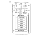
本実施形態の故障診断装置は、車両20に搭載された画像処理システムに適用される。この画像処理システムは、車載カメラ21で周囲の画像を撮影し、画像認識装置10でその画像に解析処理を施すことによって、周囲の認識対象物を認識するものである。ここでいう認識対象物には、例えば路面上の車線,他車両,障害物,人物,道路標識等が含まれる。画像認識装置10における画像認識の具体的な手法は任意であり、公知の手法を採用することができる。例えば、車載カメラ21で得られた画像の明るさを補正する露出制御やフィルタ処理,二値化処理等を施したのち、エッジ検出処理,色彩解析処理,パターンマッチング処理等を施すことによって、認識対象物の存在やその種類,位置,挙動等が把握される。
[1. vehicle]
The failure diagnosis apparatus according to the present embodiment is applied to an image processing system mounted on the
画像認識装置10には、画像処理システムの故障を診断する故障診断装置としての機能が実装される。この機能を担う部位を故障診断部1とし、図1中に示す。故障診断部1は、ハードウェア(電子制御回路)で実現してもよいし、画像認識装置10内で処理されるソフトウェアで実現してもよく、あるいはハードウェアとソフトウェアとを併用して実現してもよい。本実施形態の故障診断部1は、ソフトウェア(故障診断プログラム)で実装される。
The
車両20には、上記の車載カメラ21のほか、車速センサ22,ヨーレートセンサ23,操舵角センサ24,ディスプレイ25,スピーカ26,車両制御装置30が搭載される。車載カメラ21は、車両20の周囲の画像を撮影する撮像素子〔CCD(Charge-Coupled Device),CMOS(Complementary Metal-Oxide-Semiconductor)等〕を内蔵した撮影装置である。ここでは、車両20の周囲の路面を含む画像が撮影され、その画像(画像データ)が画像認識装置10に伝達される。また、車速センサ22,ヨーレートセンサ23,操舵角センサ24はそれぞれ、車両20の車速,ヨーレート,操舵角を検出するセンサである。これらの車両情報は画像認識装置10に伝達され、車両20の走行状態の判定に使用される。
In addition to the in-
ディスプレイ25,スピーカ26は画像認識装置10の出力装置であり、画像認識装置10での認識結果や故障診断結果はこれらに出力される。なお、車両20にカーナビゲーションシステムやカーオーディオシステム,マルチメディアシステム等が搭載されている場合には、ディスプレイ25,スピーカ26に代えて、あるいは加えて、これらのシステムに含まれる汎用の映像表示装置,音声出力装置を利用してもよい。
The
車両制御装置30は、車両20に搭載される各種装置を制御するための電子制御装置である。車両制御装置30には、例えばエンジン制御装置,ブレーキ制御装置,変速機制御装置,サスペンション制御装置,車体姿勢制御装置等が含まれる。この車両制御装置30は、車載通信網を介して画像認識装置10と互いに通信可能に接続される。これにより、画像認識装置10での認識結果が車両20の各種制御に利用可能となる。
The
[2.ハードウェア]
図2は、画像認識装置10のハードウェア構成を例示する図である。画像認識装置10には、プロセッサ11,メモリ12(メインメモリ,主記憶装置),補助記憶装置13,インタフェース装置14,記録媒体ドライブ15等が内蔵され、内部バス16を介して互いに通信可能に接続される。これらの各装置11〜15は、図示しない電力源(例えば、車載バッテリーやボタン電池等)からの電力供給を受けて動作する。
[2. hardware]
FIG. 2 is a diagram illustrating a hardware configuration of the
プロセッサ11は、制御ユニット(制御回路)や演算ユニット(演算回路),キャッシュメモリ(レジスタ群)等を内蔵する中央処理装置である。また、メモリ12は、プログラムや作業中のデータが格納される記憶装置であり、例えばROM(Read Only Memory),RAM(Random Access Memory)がこれに含まれる。一方、補助記憶装置13は、メモリ12よりも長期的に保持されるデータやプログラムが格納されるメモリ装置であり、例えばフラッシュメモリやEEPROM(Electrically Erasable Programmable Read-Only Memory)等の不揮発性メモリがこれに含まれる。
The processor 11 is a central processing unit that incorporates a control unit (control circuit), an arithmetic unit (arithmetic circuit), a cache memory (register group), and the like. The
インタフェース装置14は、画像認識装置10と外部との間の入出力(Input and Output;I/O)を司るものである。画像認識装置10は、インタフェース装置14を介して車載ネットワーク網と接続される。あるいは、インタフェース装置14を介して、車両20に搭載された車載カメラ21及び各種センサ22〜24に接続される。車載カメラ21,各種センサ22〜24や車両制御装置30と画像認識装置10との情報の授受は、インタフェース装置14を介してなされる。記録媒体ドライブ15は、光ディスクや半導体メモリ等の記録媒体17(リムーバブルメディア)に記録,保存された情報を読み取る読取装置である。
The
画像認識装置10で実施される制御のプログラムは、例えばメモリ12内に記録,保存されることとしてもよいし、補助記憶装置13の内部に記録,保存されることとしてもよい。あるいは、記録媒体17上にプログラムが記録,保存され、その記録媒体17に書き込まれている情報が、インタフェース装置14や記録媒体ドライブ15を介して画像認識装置10に読み込まれることとしてもよい。
The control program executed in the
[3.故障診断部]
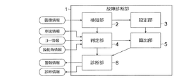
図3は、画像認識装置10の故障診断に関する故障診断部1での処理内容を説明するためのブロック図である。故障診断部1での処理内容は、例えばアプリケーションプログラムとして補助記憶装置13や記録媒体17に記録,保存され、プロセッサ11内のメモリ空間やメモリ12上に展開されて実行される。ここでの処理内容を機能的に分類すると、故障診断部1には、検知部2,設定部3,判定部4,算出部5,診断部6が設けられる。
[3. Fault diagnosis unit]
FIG. 3 is a block diagram for explaining processing contents in the
[3−1.検知部]
検知部2は、路面上の車線を車線以外のアスファルト面と区別して検知するものである。ここでは、路面上にプリントされた車線と、車線がプリントされていないアスファルト面とが画像上で識別され、その識別結果が設定部3,判定部4に伝達される。車線とアスファルト面との識別には、前述した認識対象物の把握手法と同様に、公知の車線認識アルゴリズムを採用することができる。したがって、画像認識装置10で認識対象物がすでに認識されている場合には、その認識結果から車線とアスファルト面とを検知してもよい。
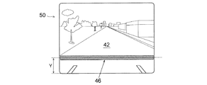
以下、車載カメラ21で撮影された画像のうち、車線が検知されたものを第一画像40と呼び、車線が検知されていないものを第二画像50と呼ぶ。また、図4,図6に示すように、これらの画像中に存在する車線及びアスファルト面のそれぞれに符号41,42を付して説明する。
[3-1. Detection unit]
The
Hereinafter, among the images captured by the in-
[3−2.設定部]
設定部3は、故障診断の対象となるエリア(領域)を設定するものである。検知部2で車線が検知されている場合、設定部3は、第一画像40に基づいて三種類のエリア43〜45を設定する。これらのエリア43〜45は、路面の旋回半径,勾配,走行レーン幅などに応じた位置に設定される。一方、検知部2で車線が検知されていない場合、設定部3は、一種類のエリア(第三エリア46)のみを設定する。これらのエリア43〜46の位置を、図4,図6中に例示する。
[3-2. Setting section]
The
第一エリア43,44は、第一画像40において車線41に対応するエリア(好ましくは、車線41を多く含むエリア)である。車線41は車両20の左右それぞれに配設されうることから、左側の車線41に対応する第一エリア43と、右側の車線41に対応する第一エリア44とが設定される。図4に示すように、第一エリア43,44は、矩形の画像における下端辺との距離が寸法Yとなる仮想線Hに沿って、水平方向に間隔を空けて並置される。第一画像40中における車線41の位置は、路面の旋回半径,勾配,走行レーン幅などによって変化する。したがって、第一エリア43,44の水平方向の位置も、路面に応じて変動する。
The
第二エリア45は、第一画像40においてアスファルト面42に対応するエリア(好ましくは、アスファルト面42を多く含むエリア)である。ここでは、車両20の走行レーンとなるアスファルト面42の中央部を含むエリアが、第二エリア45として設定される。本実施形態の第二エリア45は、左右の第一エリア43,44に挟まれた範囲内において、仮想線Hに沿って水平方向に延びる帯状領域として設定される。図4に示すように、第二エリア45の横幅は、左右の第一エリア43,44のそれぞれに対して、水平方向に所定の間隔が空くように設定される。
The
第三エリア46は、上記の三種類のエリア43〜45に対応するエリアを含む広域のエリアである。ここでは、矩形の画像のほぼ全幅にわたって、仮想線Hに沿って水平方向に延びる帯状領域が第三エリア46として設定される。なお、第三エリア46の位置は、あらかじめ設定しておいてもよい。また、第一エリア43,44がすでに設定されている場合には、少なくとも第一エリア43,44を含む程度に、第三エリア46の左右両端部を切り詰めてもよい。ここで設定された各エリア43〜46の位置の情報は、算出部5に伝達される。
The
[3−3.判定部]
判定部4は、故障診断に関する条件を判定するものである。ここでは、車両20の走行状態に関する判定と、車線41の検知状態に関する判定とが実施される。前者の判定は、車両20の走行中に故障診断を実施するためのものである。判定部4は、例えば以下の何れかの条件が成立する場合に「車両走行中である」と判断し、その情報を算出部5,診断部6に伝達する。条件中の「所定速度」は、車線41が描かれている道路を走行しているか否かを推定するための閾値であり、例えば法定速度相当の値(数十km/h)とされる。
・車速が所定速度以上である
・ヨーレートが所定値以上である
・操舵角が所定角以上である
[3-3. Judgment unit]
The
・ Vehicle speed is over a predetermined speed ・ Yaw rate is over a predetermined value ・ Steering angle is over a predetermined angle
後者の判定は、故障診断の手法を切り替えるためのものである。判定部4は、検知部2が車線41を検知したか否かを表す情報を記憶,保持するとともに、その情報を算出部5,診断部6に伝達する。情報を記憶,保持し続ける時間は、少なくとも一回の演算周期に相当する時間以上であり、好ましくは数回の演算周期に相当する時間とされる。つまり、判定部4は、直近の過去に車線41が検知されたという事実を記憶する機能を持つ。
The latter determination is for switching the method of failure diagnosis. The
上記の事実を記憶する機能は、故障診断精度を向上させる上で有用である。なぜならば、車線41が直近の過去(例えば、前回の演算周期)で検知されている場合には、第一エリア43,44や第二エリア45の鮮度(領域が設定された位置の精度)が高く、路面の状態が急変しているとは考えにくいからである。故障診断を実施する直前に得られた第一画像40に基づいて第一エリア43,44や第二エリア45を設定することで、車線41やアスファルト面42であった確度の高い領域(例えば、水たまりによって車線41が見えにくくなっている路面や、車線41のペイントが消えかかっている路面など)を診断対象とすることができ、故障の診断精度が向上する。
The function of storing the above fact is useful for improving the fault diagnosis accuracy. This is because when the
[3−4.算出部]
算出部5は、車線41が検知されていない第二画像50を対象として、設定部3で設定された各エリア43〜46の輝度を算出するものである。ここでは、第一エリア43,44のそれぞれの平均輝度AL,AR(第一輝度)と、第二エリア45の平均輝度B(第二輝度)と、第三エリア46の平均輝度Cとが算出される。平均輝度AL,ARは「第一画像40では車線41が検知されていたはずのエリア(第二画像50で車線41が検知されなくなったエリア)」の平均輝度に相当する。
[3-4. Calculation unit]
The
同様に、平均輝度Bは「第一画像40ではアスファルト面42が検知されていたはずのエリア」の平均輝度に相当する。また、平均輝度Cは「車線41,アスファルト面42に相当するだろうと予想されるエリア」の平均輝度に相当する。
平均輝度の算出手法は種々考えられる。例えば、各エリア内に存在する各画素の輝度の算術平均値(相加平均値)を算出してもよいし、相乗平均値を算出してもよい。あるいは、相加平均値と相乗平均値とを混合した値を求めてもよい。ここで算出された輝度の情報は診断部6に伝達される。
Similarly, the average luminance B corresponds to the average luminance of “the area where the
There are various methods for calculating the average luminance. For example, an arithmetic average value (arithmetic average value) of the luminance of each pixel existing in each area may be calculated, or a geometric average value may be calculated. Or you may obtain | require the value which mixed the arithmetic mean value and the geometric mean value. The information on the brightness calculated here is transmitted to the
[3−5.診断部]
診断部6は、算出部5で算出された輝度を用いて故障診断を実施するものである。この故障診断では、画像処理システムの内的要因による故障や環境要因による性能低下を含む故障状態が三種類に分類されて判定される。故障診断の実施条件は、車両走行中であって、検知部2が車線41を検知していないことである。本実施形態の診断部6は、前回の演算周期で車線41が検知されているか否かによって、二通りの故障診断手法の何れかが選択される。この選択に際し、判定部4が記憶,保持している車線41の検知履歴が参照される。
[3-5. Diagnosis Department]
The
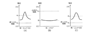
第一の故障診断手法は、前回の演算周期で車線41が検知されているときに選択される。この場合、算出部5で算出された平均輝度AL,ARのそれぞれと黒つぶれ閾値K1(第一閾値)との大小関係が比較されるとともに、平均輝度Bと白飛び閾値K2(第二閾値)との大小関係が比較される。白飛び閾値K2は、黒つぶれ閾値K1よりも大きい値(より高い輝度に相当する値)を持つ。
The first failure diagnosis method is selected when the
ここで、平均輝度ALが黒つぶれ閾値K1未満である場合には、画像処理システムに「黒つぶれ傾向」の故障が発生したものと判定される。同様に、平均輝度ARが黒つぶれ閾値K1未満である場合にも、画像処理システムに「黒つぶれ傾向」の故障が発生したものと判定される。また、平均輝度Bが白飛び閾値K2を超える場合には、画像処理システムに「白飛び傾向」の故障が発生したものと判定される。一方、図5(A)〜(C)に示すように、平均輝度AL,ARがともに黒つぶれ閾値K1以上であり、かつ、平均輝度Bが白飛び閾値K2以下である場合には、画像処理システムに性能低下が発生しているものと判定される。 Here, when the average brightness A L is smaller than the threshold K 1 underexposure is failure of the "black out tendency" is determined as that generated in the image processing system. Similarly, when the average brightness A R is smaller than the threshold K 1 underexposure also failure of the "black out tendency" is determined as that generated in the image processing system. Further, when the average luminance B exceeds overexposure threshold K 2 is the failure of the "overexposure trend" is determined as that generated in the image processing system. On the other hand, as shown in FIGS. 5A to 5C, when the average luminances A L and A R are both equal to or greater than the blackout threshold value K 1 and the average luminance B is equal to or less than the whiteout threshold value K 2. It is determined that a performance degradation has occurred in the image processing system.
第二の故障診断手法は、前回の演算周期で車線41が検知されていないときに選択される。この場合、第一エリア43,44及び第二エリア45が設定されていない可能性があり、仮に設定されていたとしても、その情報はやや古いものと考えられる。そこで診断部6は、算出部5で算出された平均輝度Cと黒つぶれ閾値K3(第三閾値)との大小関係を比較するとともに、平均輝度Cと白飛び閾値K4(第四閾値)との大小関係を比較する。白飛び閾値K4は、黒つぶれ閾値K3よりも大きい値(より高い輝度に相当する値)を持つ。また、閾値K3,K4のそれぞれは、上述の閾値K1,K2のそれぞれと同一値であってもよいし、異なる値であってもよい。
The second failure diagnosis method is selected when the
ここで、平均輝度Cが黒つぶれ閾値K3未満である場合には、画像処理システムに「黒つぶれ傾向」の故障が発生したものと判定される。また、平均輝度Cが白飛び閾値K4を超える場合には、画像処理システムに「白飛び傾向」の故障が発生したものと判定される。一方、図7に示すように、平均輝度Cが黒つぶれ閾値K3以上であり、かつ、白飛び閾値K4以下である場合には、画像処理システムに性能低下が発生しているものと判定される。 Here, when the average luminance C is less than the threshold value K 3 underexposure is failure of the "black out tendency" is determined as that generated in the image processing system. Further, when the average luminance C exceeds the threshold value K 4 whiteout is failure of the "overexposure trend" is determined as that generated in the image processing system. On the other hand, as shown in FIG. 7, the average luminance C is not less underexposure threshold K 3 or more, and, when it is overexposed threshold K 4 below, shall degradation in the image processing system is occurring determination Is done.
また、診断部6は、診断結果に対応する故障診断コード(ダイアグノーシスコード)を補助記憶装置13や記録媒体17へと出力してその情報を記録する。また、診断部6は、同一種類の故障診断コードが記録された回数をカウントし、所定回数以上になったときにその故障診断コードに対応する警報情報,診断情報を乗員に報知する。これらの警報情報,診断情報は、ディスプレイ25に表示されるとともに、スピーカ26から音声案内として出力される。
Further, the
以下に、故障診断コードの種類とそのコードが出力される原因との関係を例示する。故障診断コード1は、黒つぶれ傾向の故障が発生した可能性が高いことを示し、故障診断コード2は、白飛び傾向の故障が発生した可能性が高いことを示す。これらのコードは、画像処理システムの内的要因による故障だけでなく、環境要因による性能低下によって出力されうる。これに対し、故障診断コード3は、環境要因による性能低下が発生している可能性が高いことを示す。したがって、故障診断コードの種類が故障診断コード3であるか否かを判定することで、システムの内的要因による故障の有無を精度よく診断することができる。

上記の故障診断で用いられる閾値K1,K2,K3,K4の具体的な値は、予め設定された固定値としてもよいし、適宜算出される演算値としてもよい。
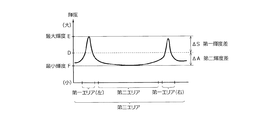
例えば、第一エリア43,44及び第二エリア45の設定時に参照された第一画像40に基づいて、閾値K1,K2を設定することが考えられる。この場合、図8に示すように、第一エリア43,44の最大輝度E(車線輝度最大値)を算出するとともに、第二エリア45の最小輝度F(アスファルト輝度最小値)を算出する。これらの最小輝度F,最大輝度Eに所定のマージンを与える定数η,γを乗じたものが、それぞれ閾値K1,K2として機能しうる(黒つぶれ閾値K1=F×η,白飛び閾値K2=E×γ)。定数γ,ηの値は、試験,実験を通じて予め取得しておくことができる。
Specific values of the threshold values K 1 , K 2 , K 3 , and K 4 used in the above-described failure diagnosis may be preset fixed values or may be calculated values that are calculated as appropriate.
For example, it is conceivable to set the threshold values K 1 and K 2 based on the
また、第一画像40に基づいて、閾値K3,K4を設定してもよい。この場合、第一画像40における第三エリア46の平均輝度Dと最大輝度E(車線輝度最大値)との差を第一輝度差ΔSとして算出するとともに、平均輝度Dと最小輝度F(アスファルト輝度最小値)との差を第二輝度差ΔAとして算出する。第二輝度差ΔAに定数βを乗じて、これを平均輝度Dから減じたものが、黒つぶれ閾値K3として機能しうる(黒つぶれ閾値K3=D−ΔA×β)。同様に、第一輝度差ΔSに所定のマージンを与える定数αを乗じて、これを平均輝度Dに加算したものが、白飛び閾値K4として機能しうる(白飛び閾値K4=D+ΔS×α)。
Further, threshold values K 3 and K 4 may be set based on the
[4.フローチャート]
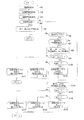
図9は、故障診断部1で実行される故障診断プログラムの手順を例示するフローチャートである。このフローは、例えばアプリケーションプログラムとして補助記憶装置13や記録媒体17に記録,保存されており、プログラムの実行時にプロセッサ11へと読み込まれて所定の周期で繰り返し実行される。
[4. flowchart]
FIG. 9 is a flowchart illustrating the procedure of a failure diagnosis program executed by the
画像認識装置10は、車載カメラ21で撮影された画像を取得するとともに(ステップA1)、車速センサ22で検出された車速の情報を取得する(ステップA2)。このとき、ヨーレートセンサ23で検出されたヨーレートや操舵角センサ24で検出された操舵角など、車両20の走行状態に関する車両情報を取得してもよい。また、画像認識装置10は、画像に解析処理を施して周囲の認識対象物を認識する(ステップA3)。ここでは、少なくとも路面上の車線41とアスファルト面42とが識別される。
The
ステップA4では、検知部2が画像中の車線41とアスファルト面42とが識別されるとともに、車線41が検知されたか否かが判定される。ここで、車線41が検知されている場合にはステップA5に進み、車線41が検知されていない場合にはステップA6に進む。ステップA5では、設定部3が故障診断の対象となる第一エリア43,44及び第二エリア45を設定する。これらのエリア43〜45の縦軸方向の座標は、図4に示すように、仮想線Hの位置に固定されている。
In step A4, the
なお、後述するステップA9〜A10で用いられる閾値K1,K2を第一画像40に基づいて設定する場合には、ここで黒つぶれ閾値K1及び白飛び閾値K2が算出される。黒つぶれ閾値K1は、第一画像40における第二エリア45の最小輝度Fに定数ηを乗じた値とされる。また、白飛び閾値K2は、第一画像40における第一エリア43,44の最大輝度Eに定数γを乗じた値とされる。その後、故障診断が実施されることなくこの演算周期での処理が終了し、次回の演算周期では再びステップA1から処理が開始される。したがって、車線41が認識されている間は、第一エリア43,44及び第二エリア45の位置が、所定の周期で繰り返し更新されることになる。一方、車線41が検知されなくなると、ステップA6以降の処理が実行される。
In the case of set based on the threshold value K 1, K 2 used in step A9~A10 described later in the
ステップA6では、判定部4において、車両20が走行中であるか否かが判定される。ここで、例えば車速が所定速度以上であれば、車両20が車線のある道路を走行しているものと判断されてステップA7に進む。一方、車速が所定速度未満であれば、車両20が車線のない道路を走行している(例えば、狭い私道や路地を走行している)ものと判断されて、この演算周期での処理が終了する。なお、車速を判定する代わりに、車両20の操舵角又はヨーレートの大きさが所定値以上であることを判定してもよい。
ステップA7では、判定部4において、車線41が前回の演算周期で検知されているか否かが判定される。この条件が成立するとステップA8に進み、今回の演算周期で得られた第二画像50を対象として、算出部5が第一エリア43,44及び第二エリア46の平均輝度AL,AR,Bを算出する。
In step A6, the
In Step A7, the
ステップA9では、診断部6において、第一エリア43,44の平均輝度AL,ARが、ともに黒つぶれ閾値K1以上であるか否かが判定される。なお、第一エリア43,44の平均輝度AL,ARは、第二エリア45の平均輝度Bよりも高い値となりやすい傾向を持つ。したがって、比較的小さい輝度に相当する黒つぶれ閾値K1を用いた判定において、誤判定を発生しにくくするためには、第二エリア45の平均輝度Bを使用するよりも第一エリア43,44の平均輝度AL,ARを使用した方が有利となる。ここで、平均輝度AL,ARの何れかが黒つぶれ閾値K1未満である場合にはステップA11に進み、診断部6が故障診断コード1を出力して、この演算周期での処理が終了する。一方、平均輝度AL,ARがともに黒つぶれ閾値K1以上であれば、ステップA10に進む。
In step A9, the
ステップA10では、第二エリア45の平均輝度Bが白飛び閾値K2以下であるか否かが判定される。第二エリア45の平均輝度Bは、第一エリア43,44の平均輝度AL,ARよりも低い値となりやすい傾向を持つ。したがって、比較的大きい輝度に相当する白飛び閾値K2を用いた判定において、誤判定を発生しにくくするためには、第一エリア43,44の平均輝度AL,ARを使用するよりも第二エリア45の平均輝度Bを使用した方が有利となる。ここで、平均輝度Bが白飛び閾値K2を超える場合にはステップA12に進み、診断部6が故障診断コード2を出力して、この演算周期での処理が終了する。一方、平均輝度Bが白飛び閾値K2以下ならばステップA13に進み、診断部6が故障診断コード3を出力して、この演算周期での処理が終了する。
In step A10, the average whether luminance B is less than the threshold value K 2 whiteout
一方、ステップA7において、前回の演算周期で車線41が検知されていない場合にはステップA14に進み、今回の演算周期で得られた第二画像50を対象として、算出部5が第三エリア46の平均輝度Cを算出する。なお、これに続くステップA15〜A16で用いられる閾値K3,K4を直近の第一画像40に基づいて設定する場合には、ここで黒つぶれ閾値K3及び白飛び閾値K4が算出される。黒つぶれ閾値K3は、直近の第一画像40における第三エリア46の平均輝度Dと最小輝度Fとに基づいて算出される。同様に、白飛び閾値K4は、平均輝度Dと最大輝度Eとに基づいて算出される。
On the other hand, in step A7, when the
ステップA15では、診断部6において、第三エリア46の平均輝度Cが黒つぶれ閾値K3以上であるか否かが判定される。ここで、平均輝度Cが黒つぶれ閾値K3未満である場合にはステップA17に進み、診断部6が故障診断コード1を出力して、この演算周期での処理が終了する。また、平均輝度Cが黒つぶれ閾値K3以上ならばステップA16に進み、平均輝度Cが白飛び閾値K4以下であるか否かが判定される。ここで、平均輝度Cが白飛び閾値K4を超える場合にはステップA18に進み、診断部6が故障診断コード2を出力して、この演算周期での処理が終了する。一方、平均輝度Cが白飛び閾値K4以下ならばステップA19に進み、診断部6が故障診断コード3を出力して、この演算周期での処理が終了する。このような処理が繰り返された後、何れかの故障診断コードの出力回数が所定回数以上に達すると、その故障診断コードに対応する警報情報,診断情報がディスプレイ25,スピーカ26へと伝達され、乗員に報知される。
In step A15, the
[5.作用,効果]
(1)上記の故障診断部1(または、これを含む画像認識装置10)では、車線41の検知中に撮影された第一画像40に基づき、第一エリア43,44と第二エリア45とが設定される。また、その後に車線41が検知されなくなると、第二画像50における第一エリア43,44の平均輝度AL,ARと、第二エリア45の平均輝度Bとが算出される。これらの平均輝度AL,AR,Bに基づいて故障を判定することで、車線やアスファルト面であった可能性の高い領域を診断対象領域とすることができ、故障診断精度を向上させることができる。また、上記の故障診断部1では、表1に示すように、システムの内的要因による故障と環境要因による性能低下とを識別して診断することができるため、故障診断精度を向上させることができる。
[5. Action, effect]
(1) In the above-described failure diagnosis unit 1 (or the
(2)上記の故障診断部1では、輝度に基づく判定に際し、第一エリア43,44の平均輝度AL,ARのそれぞれが黒つぶれ閾値K1未満である場合に、画像処理システムに「黒つぶれ傾向」の故障が発生したものと判定される。このように、比較的大きな輝度値を持ちやすい平均輝度AL,ARと、比較的小さい輝度に相当する黒つぶれ閾値K1との大小関係を判定することで、低露出(暗すぎること)による誤判定を抑制することができる。
また、上記の故障診断部1では、輝度に基づく判定に際し、第二エリア45の平均輝度Bが白飛び閾値を超える場合に、画像処理システムに「白飛び傾向」の故障が発生したものと判定される。このように、比較的小さな輝度値を持ちやすい平均輝度Bと、比較的大きい輝度に相当する白飛び閾値K2との大小関係を判定することで、高露出(明るすぎること)による誤判定を抑制することができる。
したがって、露出故障の誤判定の発生を抑制することができ、故障診断精度を向上させることができる。
(2) In the
Further, in the above-described
Therefore, the occurrence of erroneous determination of exposure failure can be suppressed, and failure diagnosis accuracy can be improved.
(3)上記の故障診断で用いられる黒つぶれ閾値K1は、第一画像40における第二エリア45の最小輝度F(アスファルト輝度最小値)に応じて設定可能である。この場合、車線41が検知されたときの走行シーンにおけるアスファルト面42の実測値に基づいて黒つぶれ閾値K1を与えることができ、走行シーンの環境を基準とした故障診断を実現することができる。したがって、日射量や時間帯に左右されることなく、第一エリア43,44が黒つぶれしているか否かを精度よく判断することができ、画像処理システムの故障診断精度をさらに向上させることができる。
(3) underexposure threshold K 1 used in the above fault diagnosis can be set according to the minimum luminance F of the
(4)同様に、本件の故障診断で用いられる白飛び閾値K2は、第一画像40における第一エリア43,44の最大輝度E(車線輝度最大値)に応じて設定可能である。この場合、車線41が検知されたときの走行シーンにおける車線41の実測値に基づいて白飛び閾値K2を与えることができる。したがって、第二エリア45が白飛びしているか否かを精度よく判断することができ、画像処理システムの故障診断精度をさらに向上させることができる。
(4) Similarly, the whiteout threshold value K 2 used in the failure diagnosis of the present case can be set according to the maximum luminance E (lane luminance maximum value) of the
(5)上記の故障診断部1では、第一エリア43,44や第二エリア45だけでなく、第三エリア46も設定される。この第三エリア46は、図4,図6中に示すように、左右の第一エリア43,44及び第二エリア45に対応するエリアを含む広域のエリアとして設定される。また、算出部5では、第三エリア46の平均輝度Cが算出され、この平均輝度Cに基づいて故障診断が実施される。このような判定手法を採用することで、前回の演算周期で車線41を検知していない場合であっても、車線41やアスファルト面42であるはずのエリアについての平均輝度Cを診断することができ、故障診断精度を向上させることができる。
(5) In the
(6)上記の故障診断部1では、第三エリア46の平均輝度Cが黒つぶれ閾値K3未満である場合に、画像処理システムに「黒つぶれ傾向」の故障が発生したものと判定される。また、平均輝度Cが白飛び閾値K4を超える場合には、画像処理システムに「白飛び傾向」の故障が発生したものと判定される。これにより、車線41が検知されていない状態での故障判定を実施することができる。また、車載カメラ21の露出状態に起因する誤検出を抑制することができ、故障判定精度を向上させることができる。
(6) In the
(7)上記の故障診断で用いられる黒つぶれ閾値K3及び白飛び閾値K4は、直近の第一画像40における第三エリア46の平均輝度D,第二エリア45の最小輝度F,第一エリア43,44の最大輝度Eに応じて設定される。これにより、過去(例えば、前回の演算周期)に車線41が検知されていなかったとしても、走行シーンの環境を基準とした閾値K3,K4を与えることができ、画像処理システムの故障診断精度をさらに向上させることができる。
(7) underexposure threshold K 3 and overexposure threshold K 4 used in the above fault diagnosis, the average brightness D of the
(8)上記の故障診断部1では、車両20が走行中であることを条件として、故障診断が実施される。例えば、車速が所定車速以上であるときには、狭い私道や路地を走行しているのではなく、車線41が描かれている道路を走行しているものと判断されて、故障診断が実施される。これにより、診断に適した路面環境を特定することが可能となり、故障診断精度をさらに向上させることができる。
また、車速が所定車速未満の状態では、故障診断が実施されない。これにより、例えば駐車場やガソリンスタンドの路面にペイントされた車線41以外の表示記号に基づく誤診断を防止することができる。このような点においても、「車両の車速が所定車速以上であること」を故障診断の実施条件の一つとすることは、故障診断精度の向上に貢献しうる。
(8) In the
Further, failure diagnosis is not performed when the vehicle speed is lower than the predetermined vehicle speed. Thereby, for example, misdiagnosis based on display symbols other than the
(9)上記の故障診断部1では、ヨーレートが所定値以上であることや、操舵角が所定各以上であることも、故障診断の実施条件の一つとされている。このように、車両20の操舵角やヨーレートが大きい旋回状態では、車両20が車線のある道路を走行中であると推定できる。したがって、故障診断精度をさらに向上させることができる。
(9) In the
[6.変形例]
上述の実施形態では、画像認識装置10の内部に故障診断部1が設けられたものを例示したが、故障診断部1を画像認識装置10の外部に設けることも可能である。例えば、故障診断部1を車両制御装置30に内蔵させてもよいし、故障診断部1を独立した一つの電子制御装置として設けてもよい。また、車両20が無線通信機能を搭載している場合には、ネットワーク上のコンピュータやサーバ内に故障診断部1を設けることが可能である。さらに、故障診断部1としての機能を複数の電子制御装置に分散させて配置することも可能である。
[6. Modified example]
In the above-described embodiment, an example in which the
また、上述の実施形態では、車両20の走行状態の判定に際し、車速,ヨーレート,操舵角を用いるものを例示したが、この判定に係る具体的なパラメータは種々考えられる。例えば、車両20に搭載されたエンジンやモータの回転数,トルク,駆動軸回転数,駆動軸トルク等が所定値以上である場合に「車両走行中である」と判断してもよい。あるいは、車両20の横加速度や駆動輪の切れ角に基づき、旋回状態を判断してもよい。
In the above-described embodiment, the vehicle speed, yaw rate, and steering angle are exemplified when determining the traveling state of the
また、上述の実施形態では、例えば図9のステップA9,A10に示すように、第一エリア43,44の平均輝度AL,ARと第二エリア45の平均輝度Bとを併用した故障診断手法を例示したが、これらの何れか一方のみを用いて故障診断を実施してもよい。さらに、上述の実施形態では、左側の車線41に対応する第一エリア43と右側の車線41に対応する第一エリア44とが設定されているが、これらの何れか一方のみを設定することも可能である。少なくとも一つ以上の平均輝度情報を用いることで、上記の表1における故障診断コード1又は2に対応する状態と、故障診断コード3に対応する状態とを識別することができ、故障診断精度を向上させることができる。
In the above-described embodiment, for example, as shown in steps A9 and A10 of FIG. 9, the failure diagnosis using the average luminances A L and A R of the
[7.付記]
以上の変形例を含む実施形態に関し、さらに以下の付記を開示する。
[7−1.プロセッサを含む故障診断装置]
(付記1)
車載カメラで撮影された画像を処理するシステムの故障を診断する故障診断装置において、
プロセッサと、メモリと、
前記プロセッサで実行され、路面上の車線を前記車線以外のアスファルト面と区別して検知する検知部と、
前記プロセッサで実行され、前記車線の検知中に撮影された第一画像において、前記車線に対応する第一エリアと前記アスファルト面に対応する第二エリアとを設定する設定部と、
前記プロセッサで実行され、車両走行中かつ前記車線の非検知時に撮影された第二画像において、前記第一エリアの第一輝度と前記第二エリアの第二輝度とを算出する算出部と、
前記プロセッサで実行され、前記第一輝度及び前記第二輝度の少なくとも一方に基づき、前記故障を診断する診断部と、
を備えたことを特徴とする、故障診断装置。
(付記2)
前記診断部は、前記第一輝度が第一閾値未満である場合、又は、前記第二輝度が前記第一閾値よりも大きい第二閾値を超える場合に、前記故障が発生したものと診断する
ことを特徴とする、付記1記載の故障診断装置。
(付記3)
前記第一閾値が、前記第一画像における前記第二エリアの最小輝度に応じて設定される
ことを特徴とする、付記2記載の故障診断装置。
(付記4)
前記第二閾値が、前記第一画像における前記第一エリアの最大輝度に応じて設定される
ことを特徴とする、付記2又は3記載の故障診断装置。
(付記5)
前記算出部は、前回の演算周期で前記検知部が前記車線を検知していない場合に、前記第二画像における前記第一エリア及び前記第二エリアに対応する第三エリアの平均輝度を算出し、
前記診断部が、前記平均輝度に基づき、前記故障を診断する
ことを特徴とする、付記1〜4の何れか1項に記載の故障診断装置。
(付記6)
前記診断部は、前記平均輝度が第三閾値未満である場合、又は、前記平均輝度が前記第三閾値よりも大きい第四閾値を超える場合に、前記故障が発生したものと診断する
ことを特徴とする、付記5記載の故障診断装置。
(付記7)
前記第三閾値及び前記第四閾値が、直近の前記第一画像における前記第三エリアの平均輝度、前記第二エリアの最小輝度、及び、前記第一エリアの最大輝度に応じて設定される
ことを特徴とする、付記5又は6記載の故障診断装置。
(付記8)
前記故障診断の実施条件の一つは、前記車両の車速が所定車速以上であることである
ことを特徴とする、付記1〜7の何れか1項に記載の故障診断装置。
(付記9)
前記故障診断の実施条件の一つは、前記車両の操舵角又はヨーレートの大きさが所定値以上であることである
ことを特徴とする、付記1〜8の何れか1項に記載の故障診断装置。
(付記10)
前回の演算周期で前記検知部が前記車線を検知したことを判定する判定部を備える
ことを特徴とする、付記1〜9の何れか1項に記載の故障診断装置。
(補足)
付記1〜10において、前記算出部が前記第一輝度と前記第二輝度とを算出するのは、前回の演算周期で前記検知部が前記車線を検知した場合であることが好ましい。
また、前記診断部は、前記第一輝度及び前記第二輝度の少なくとも一方と閾値とを比較することで前記故障診断をすることが好ましい。この場合、前記第一輝度及び前記第二輝度が所定範囲内にあるか否かを判定することが好ましい。
さらに、前記診断部は、前記システムの内的要因による故障や環境要因による性能低下を含む故障状態を診断することが好ましい。また、前記診断部は、前記内的要因による故障と環境要因による性能低下とを識別することが好ましい。
[7. Addendum]
The following additional remarks are disclosed with respect to the embodiment including the above modification.
[7-1. Fault diagnosis device including processor]
(Appendix 1)
In a failure diagnosis device that diagnoses a failure of a system that processes an image taken by an in-vehicle camera,
Processor, memory,
A detection unit that is executed by the processor and detects a lane on a road surface separately from an asphalt surface other than the lane;
In a first image executed by the processor and photographed during detection of the lane, a setting unit for setting a first area corresponding to the lane and a second area corresponding to the asphalt surface;
In the second image executed by the processor and photographed when the vehicle is running and the lane is not detected, a calculation unit that calculates the first luminance of the first area and the second luminance of the second area;
A diagnostic unit that is executed by the processor and diagnoses the failure based on at least one of the first luminance and the second luminance;
A failure diagnosis apparatus comprising:
(Appendix 2)
The diagnosis unit diagnoses that the failure has occurred when the first luminance is less than a first threshold or when the second luminance exceeds a second threshold greater than the first threshold. The failure diagnosis apparatus according to
(Appendix 3)
The failure diagnosis apparatus according to
(Appendix 4)
The fault diagnosis apparatus according to
(Appendix 5)
The calculation unit calculates an average luminance of a third area corresponding to the first area and the second area in the second image when the detection unit does not detect the lane in the previous calculation cycle. ,
The failure diagnosis apparatus according to any one of
(Appendix 6)
The diagnostic unit diagnoses that the failure has occurred when the average luminance is less than a third threshold or when the average luminance exceeds a fourth threshold that is greater than the third threshold. The failure diagnosis apparatus according to
(Appendix 7)
The third threshold value and the fourth threshold value are set according to the average brightness of the third area, the minimum brightness of the second area, and the maximum brightness of the first area in the latest first image. The failure diagnosis apparatus according to
(Appendix 8)
One of the execution conditions of the said fault diagnosis is that the vehicle speed of the said vehicle is more than predetermined vehicle speed, The fault diagnostic apparatus in any one of the appendixes 1-7 characterized by the above-mentioned.
(Appendix 9)
The failure diagnosis according to any one of
(Appendix 10)
The failure diagnosis apparatus according to any one of
(Supplement)
In
Further, it is preferable that the diagnosis unit performs the failure diagnosis by comparing at least one of the first luminance and the second luminance with a threshold value. In this case, it is preferable to determine whether or not the first luminance and the second luminance are within a predetermined range.
Furthermore, it is preferable that the diagnosis unit diagnoses a failure state including a failure due to an internal factor of the system and a performance deterioration due to an environmental factor. Further, it is preferable that the diagnosis unit discriminates between a failure due to the internal factor and a performance degradation due to an environmental factor.
[7−2.故障診断プログラム]
(付記11)
車載カメラ(で撮影された画像を処理するシステムの故障を診断する故障診断プログラムにおいて、
路面上の車線を前記車線以外のアスファルト面と区別して検知し、
前記車線の検知中に撮影された第一画像において、前記車線に対応する第一エリアと前記アスファルト面に対応する第二エリアとを設定し、
車両走行中かつ前記車線の非検知時に撮影された第二画像において、前記第一エリアの第一輝度と前記第二エリアの第二輝度とを算出し、
前記第一輝度及び前記第二輝度の少なくとも一方に基づき、前記故障を診断する
処理をコンピュータに実行させる、故障診断プログラム。
(付記12)
前記第一輝度が第一閾値未満である場合、又は、前記第二輝度が前記第一閾値よりも大きい第二閾値を超える場合に、前記故障が発生したものと診断する
処理をコンピュータに実行させる、付記11記載の故障診断プログラム。
(付記13)
前記第一閾値が、前記第一画像における前記第二エリアの最小輝度に応じて設定される
処理をコンピュータに実行させる、付記12記載の故障診断プログラム。
(付記14)
前記第二閾値が、前記第一画像における前記第一エリアの最大輝度に応じて設定される
処理をコンピュータに実行させる、付記12または13記載の故障診断プログラム。
(付記15)
前回の演算周期で前記検知部が前記車線を検知していない場合に、前記第二画像における前記第一エリア及び前記第二エリアに対応する第三エリアの平均輝度を算出し、
前記平均輝度に基づき、前記故障を診断する
処理をコンピュータに実行させる、付記11〜14の何れか1項に記載の故障診断プログラム。
(付記16)
前記平均輝度が第三閾値未満である場合、又は、前記平均輝度が前記第三閾値よりも大きい第四閾値を超える場合に、前記故障が発生したものと診断する
処理をコンピュータに実行させる、付記15記載の故障診断プログラム。
(付記17)
前記第三閾値及び前記第四閾値が、直近の前記第一画像における前記第三エリアの平均輝度、前記第二エリアの最小輝度、及び、前記第一エリアの最大輝度に応じて設定される
処理をコンピュータに実行させる、付記15又は16記載の故障診断プログラム。
(付記18)
前記車両の車速が所定車速以上であることを、前記故障診断の実施条件の一つとする
処理をコンピュータに実行させる、付記11〜17の何れか1項に記載の故障診断プログラム。
(付記19)
前記車両の操舵角又はヨーレートの大きさが所定値以上であることを、前記故障診断の実施条件の一つとする
処理をコンピュータに実行させる、付記11〜18の何れか1項に記載の故障診断プログラム。
(付記20)
前回の演算周期で前記検知部が前記車線を検知したことを判定する
処理をコンピュータに実行させる、付記11〜19の何れか1項に記載の故障診断プログラム。
[7-2. Fault diagnosis program]
(Appendix 11)
In the fault diagnosis program for diagnosing faults in the system that processes images taken with the in-vehicle camera (
Detecting lanes on the road surface separately from asphalt surfaces other than the above lanes,
In the first image taken during the detection of the lane, set a first area corresponding to the lane and a second area corresponding to the asphalt surface,
In the second image taken when the vehicle is running and the lane is not detected, the first luminance of the first area and the second luminance of the second area are calculated,
A failure diagnosis program for causing a computer to execute a process of diagnosing the failure based on at least one of the first luminance and the second luminance.
(Appendix 12)
When the first luminance is less than the first threshold value, or when the second luminance exceeds a second threshold value greater than the first threshold value, the computer is caused to execute a process of diagnosing that the failure has occurred. The fault diagnosis program according to appendix 11.
(Appendix 13)
The failure diagnosis program according to
(Appendix 14)
14. The failure diagnosis program according to
(Appendix 15)
When the detection unit has not detected the lane in the previous calculation cycle, the average luminance of the third area corresponding to the first area and the second area in the second image,
The failure diagnosis program according to any one of appendices 11 to 14, which causes a computer to execute a process of diagnosing the failure based on the average luminance.
(Appendix 16)
When the average brightness is less than a third threshold value, or when the average brightness exceeds a fourth threshold value that is greater than the third threshold value, the computer is caused to execute a process of diagnosing that the failure has occurred. 15. The failure diagnosis program according to 15.
(Appendix 17)
Processing in which the third threshold value and the fourth threshold value are set according to the average brightness of the third area, the minimum brightness of the second area, and the maximum brightness of the first area in the most recent first image. The failure diagnosis program according to
(Appendix 18)
18. The failure diagnosis program according to any one of appendices 11 to 17, which causes a computer to execute a process in which the vehicle speed of the vehicle is equal to or higher than a predetermined vehicle speed as one of the execution conditions of the failure diagnosis.
(Appendix 19)
The fault diagnosis according to any one of appendices 11 to 18, which causes a computer to execute a process in which the steering angle or yaw rate of the vehicle is equal to or greater than a predetermined value as one of the execution conditions of the fault diagnosis. program.
(Appendix 20)
The fault diagnosis program according to any one of appendices 11 to 19, which causes a computer to execute a process of determining that the detection unit has detected the lane in a previous calculation cycle.
1 故障診断部
2 検知部
3 設定部
4 判定部
5 算出部
6 診断部
10 画像認識装置
20 車両
21 車載カメラ
22 車速センサ
23 ヨーレートセンサ
24 操舵角センサ
25 ディスプレイ
26 スピーカ
40 第一画像
41 車線
42 アスファルト面
43 第一エリア(左側)
44 第一エリア(右側)
45 第二エリア
46 第三エリア
50 第二画像
K1 黒つぶれ閾値(第一閾値)
K2 白飛び閾値(第二閾値)
K3 黒つぶれ閾値(第三閾値)
K4 白飛び閾値(第四閾値)
AL,AR 第一エリアの平均輝度(第一輝度)
B 第二エリアの平均輝度(第二輝度)
C 第三エリアの平均輝度(今回の演算周期)
DESCRIPTION OF
44 First area (right side)
45
K 1 Blackout threshold (first threshold)
K 2 whiteout threshold (second threshold)
K 3 Blackout threshold (third threshold)
K 4 Whiteout threshold (fourth threshold)
A L , A R 1st area average brightness (1st brightness)
B Average brightness of second area (second brightness)
C Average brightness in area 3 (current calculation cycle)
Claims (9)
路面上の車線を前記車線以外のアスファルト面と区別して検知する検知部と、
前記車線の検知中に撮影された第一画像において、前記車線に対応する第一エリアと前記アスファルト面に対応する第二エリアとを設定する設定部と、
車両走行中かつ前記車線の非検知時に撮影された第二画像において、前記第一エリアの第一輝度と前記第二エリアの第二輝度とを算出する算出部と、
前記第一輝度及び前記第二輝度の少なくとも一方に基づき、前記故障を診断する診断部と、
を備えたことを特徴とする、故障診断装置。 In a failure diagnosis device that diagnoses a failure of a system that processes an image taken by an in-vehicle camera,
A detection unit for detecting a lane on the road surface separately from an asphalt surface other than the lane,
In the first image taken during the detection of the lane, a setting unit for setting a first area corresponding to the lane and a second area corresponding to the asphalt surface;
In the second image taken when the vehicle is running and the lane is not detected, a calculation unit that calculates the first luminance of the first area and the second luminance of the second area;
Based on at least one of the first luminance and the second luminance, a diagnostic unit that diagnoses the failure;
A failure diagnosis apparatus comprising:
ことを特徴とする、請求項1記載の故障診断装置。 The diagnosis unit diagnoses that the failure has occurred when the first luminance is less than a first threshold or when the second luminance exceeds a second threshold greater than the first threshold. The failure diagnosis apparatus according to claim 1, wherein:
ことを特徴とする、請求項2記載の故障診断装置。 The failure diagnosis apparatus according to claim 2, wherein the first threshold is set according to a minimum luminance of the second area in the first image.
ことを特徴とする、請求項2又は3記載の故障診断装置。 The failure diagnosis apparatus according to claim 2, wherein the second threshold is set according to a maximum luminance of the first area in the first image.
前記診断部が、前記平均輝度に基づき、前記故障を診断する
ことを特徴とする、請求項1〜4の何れか1項に記載の故障診断装置。 The calculation unit calculates an average luminance of a third area corresponding to the first area and the second area in the second image when the detection unit does not detect the lane in the previous calculation cycle. ,
The failure diagnosis apparatus according to claim 1, wherein the diagnosis unit diagnoses the failure based on the average luminance.
ことを特徴とする、請求項5記載の故障診断装置。 The diagnostic unit diagnoses that the failure has occurred when the average luminance is less than a third threshold or when the average luminance exceeds a fourth threshold that is greater than the third threshold. The failure diagnosis apparatus according to claim 5.
ことを特徴とする、請求項5又は6記載の故障診断装置。 The third threshold value and the fourth threshold value are set according to the average brightness of the third area, the minimum brightness of the second area, and the maximum brightness of the first area in the latest first image. The fault diagnosis apparatus according to claim 5 or 6, characterized in that.
ことを特徴とする、請求項1〜7の何れか1項に記載の故障診断装置。 The failure diagnosis apparatus according to claim 1, wherein one of the conditions for performing the failure diagnosis is that the vehicle speed of the vehicle is equal to or higher than a predetermined vehicle speed.
ことを特徴とする、請求項1〜8の何れか1項に記載の故障診断装置。 The failure diagnosis according to any one of claims 1 to 8, wherein one of the execution conditions of the failure diagnosis is that the steering angle or yaw rate of the vehicle is greater than or equal to a predetermined value. apparatus.
Priority Applications (3)
| Application Number | Priority Date | Filing Date | Title |
|---|---|---|---|
| JP2015134975A JP6571424B2 (en) | 2015-07-06 | 2015-07-06 | Fault diagnosis device |
| EP16177210.8A EP3115930A1 (en) | 2015-07-06 | 2016-06-30 | Malfunction diagnosis apparatus |
| US15/202,527 US10635910B2 (en) | 2015-07-06 | 2016-07-05 | Malfunction diagnosis apparatus |
Applications Claiming Priority (1)
| Application Number | Priority Date | Filing Date | Title |
|---|---|---|---|
| JP2015134975A JP6571424B2 (en) | 2015-07-06 | 2015-07-06 | Fault diagnosis device |
Publications (2)
| Publication Number | Publication Date |
|---|---|
| JP2017017635A true JP2017017635A (en) | 2017-01-19 |
| JP6571424B2 JP6571424B2 (en) | 2019-09-04 |
Family
ID=56851335
Family Applications (1)
| Application Number | Title | Priority Date | Filing Date |
|---|---|---|---|
| JP2015134975A Expired - Fee Related JP6571424B2 (en) | 2015-07-06 | 2015-07-06 | Fault diagnosis device |
Country Status (3)
| Country | Link |
|---|---|
| US (1) | US10635910B2 (en) |
| EP (1) | EP3115930A1 (en) |
| JP (1) | JP6571424B2 (en) |
Cited By (6)
| Publication number | Priority date | Publication date | Assignee | Title |
|---|---|---|---|---|
| WO2018225210A1 (en) * | 2017-06-08 | 2018-12-13 | 三菱電機株式会社 | Abnormality detection device and abnormality detection method |
| JP2019211852A (en) * | 2018-05-31 | 2019-12-12 | トヨタ自動車株式会社 | Object monitoring device |
| JP2020060927A (en) * | 2018-10-10 | 2020-04-16 | 三菱電機株式会社 | Image processing device |
| KR20200113153A (en) * | 2019-03-15 | 2020-10-06 | 엘지전자 주식회사 | Vehicle control device |
| US10848756B2 (en) | 2019-03-08 | 2020-11-24 | Kabushiki Kaisha Toshiba | Image processing apparatus and failure detection method for image processing apparatus |
| KR20210005439A (en) * | 2019-07-05 | 2021-01-14 | 현대자동차주식회사 | Advanced Driver Assistance System, Vehicle having the same and method for controlling the vehicle |
Families Citing this family (5)
| Publication number | Priority date | Publication date | Assignee | Title |
|---|---|---|---|---|
| US10402666B2 (en) * | 2017-12-18 | 2019-09-03 | Ford Global Technologies, Llc | Vehicle monitoring of infrastructure lighting |
| CN111093007B (en) * | 2018-10-23 | 2021-04-06 | 辽宁石油化工大学 | Walking control method and device for biped robot, storage medium and terminal |
| US11757706B2 (en) | 2019-07-19 | 2023-09-12 | Razberi Secure Technologies, Llc | Switch monitoring system and method of use |
| CN111553886B (en) * | 2020-04-09 | 2024-02-13 | 哈尔滨工业大学 | An adaptive identification method for particles in asphalt mixture CT images |
| JP7537314B2 (en) * | 2021-03-01 | 2024-08-21 | トヨタ自動車株式会社 | Vehicle surroundings monitoring device and vehicle surroundings monitoring system |
Citations (6)
| Publication number | Priority date | Publication date | Assignee | Title |
|---|---|---|---|---|
| JPH09113221A (en) * | 1995-10-17 | 1997-05-02 | Mitsubishi Electric Corp | Vehicle-mounted image processing apparatus and image processing method thereof |
| JPH09319873A (en) * | 1996-05-28 | 1997-12-12 | Mitsubishi Electric Corp | In-vehicle image processing device |
| JP2003255430A (en) * | 2002-02-28 | 2003-09-10 | Toshiba Corp | Video diagnostic device, video diagnostic system for in-vehicle video monitoring device |
| JP2005073296A (en) * | 2004-10-27 | 2005-03-17 | Mitsubishi Electric Corp | Exposure control device for vehicle camera |
| US20130194424A1 (en) * | 2012-01-30 | 2013-08-01 | Clarion Co., Ltd. | Exposure controller for on-vehicle camera |
| JP2014187496A (en) * | 2013-03-22 | 2014-10-02 | Denso Corp | Fault detection device |
Family Cites Families (6)
| Publication number | Priority date | Publication date | Assignee | Title |
|---|---|---|---|---|
| JP2005033680A (en) | 2003-07-10 | 2005-02-03 | Toyota Motor Corp | Image processing apparatus for vehicle |
| JP4258385B2 (en) * | 2004-01-14 | 2009-04-30 | 株式会社デンソー | Road surface reflection detector |
| US7580070B2 (en) * | 2005-03-31 | 2009-08-25 | Freescale Semiconductor, Inc. | System and method for roll-off correction in image processing |
| JP4659631B2 (en) * | 2005-04-26 | 2011-03-30 | 富士重工業株式会社 | Lane recognition device |
| JP4114752B2 (en) * | 2005-08-09 | 2008-07-09 | 三菱電機株式会社 | Imaging device |
| JP5375814B2 (en) * | 2010-12-22 | 2013-12-25 | 株式会社デンソー | Exposure control device |
-
2015
- 2015-07-06 JP JP2015134975A patent/JP6571424B2/en not_active Expired - Fee Related
-
2016
- 2016-06-30 EP EP16177210.8A patent/EP3115930A1/en not_active Withdrawn
- 2016-07-05 US US15/202,527 patent/US10635910B2/en not_active Expired - Fee Related
Patent Citations (7)
| Publication number | Priority date | Publication date | Assignee | Title |
|---|---|---|---|---|
| JPH09113221A (en) * | 1995-10-17 | 1997-05-02 | Mitsubishi Electric Corp | Vehicle-mounted image processing apparatus and image processing method thereof |
| JPH09319873A (en) * | 1996-05-28 | 1997-12-12 | Mitsubishi Electric Corp | In-vehicle image processing device |
| JP2003255430A (en) * | 2002-02-28 | 2003-09-10 | Toshiba Corp | Video diagnostic device, video diagnostic system for in-vehicle video monitoring device |
| JP2005073296A (en) * | 2004-10-27 | 2005-03-17 | Mitsubishi Electric Corp | Exposure control device for vehicle camera |
| US20130194424A1 (en) * | 2012-01-30 | 2013-08-01 | Clarion Co., Ltd. | Exposure controller for on-vehicle camera |
| JP2013157770A (en) * | 2012-01-30 | 2013-08-15 | Clarion Co Ltd | On-vehicle camera exposure control device |
| JP2014187496A (en) * | 2013-03-22 | 2014-10-02 | Denso Corp | Fault detection device |
Cited By (9)
| Publication number | Priority date | Publication date | Assignee | Title |
|---|---|---|---|---|
| WO2018225210A1 (en) * | 2017-06-08 | 2018-12-13 | 三菱電機株式会社 | Abnormality detection device and abnormality detection method |
| JPWO2018225210A1 (en) * | 2017-06-08 | 2019-11-07 | 三菱電機株式会社 | Abnormality detection device and abnormality detection method |
| JP2019211852A (en) * | 2018-05-31 | 2019-12-12 | トヨタ自動車株式会社 | Object monitoring device |
| JP2020060927A (en) * | 2018-10-10 | 2020-04-16 | 三菱電機株式会社 | Image processing device |
| US10848756B2 (en) | 2019-03-08 | 2020-11-24 | Kabushiki Kaisha Toshiba | Image processing apparatus and failure detection method for image processing apparatus |
| KR20200113153A (en) * | 2019-03-15 | 2020-10-06 | 엘지전자 주식회사 | Vehicle control device |
| KR102183130B1 (en) | 2019-03-15 | 2020-11-25 | 엘지전자 주식회사 | Vehicle control device |
| KR20210005439A (en) * | 2019-07-05 | 2021-01-14 | 현대자동차주식회사 | Advanced Driver Assistance System, Vehicle having the same and method for controlling the vehicle |
| KR102763116B1 (en) | 2019-07-05 | 2025-02-10 | 현대자동차주식회사 | Advanced Driver Assistance System, Vehicle having the same and method for controlling the vehicle |
Also Published As
| Publication number | Publication date |
|---|---|
| JP6571424B2 (en) | 2019-09-04 |
| EP3115930A1 (en) | 2017-01-11 |
| US10635910B2 (en) | 2020-04-28 |
| US20170011271A1 (en) | 2017-01-12 |
Similar Documents
| Publication | Publication Date | Title |
|---|---|---|
| JP6571424B2 (en) | Fault diagnosis device | |
| US10860869B2 (en) | Time to collision using a camera | |
| US10339812B2 (en) | Surrounding view camera blockage detection | |
| JP6364797B2 (en) | Image analysis apparatus and image analysis method | |
| CN103269908B (en) | Image-rendering device | |
| JP6257792B2 (en) | Camera covering state recognition method, camera system, and automobile | |
| EP3690847B1 (en) | Lift-up determining device and lift-up determining method | |
| EP3140777B1 (en) | Method for performing diagnosis of a camera system of a motor vehicle, camera system and motor vehicle | |
| JP3312729B2 (en) | Outside monitoring device with fail-safe function | |
| CN107798688B (en) | Moving target identification method, early warning method and automobile rear-end collision prevention early warning device | |
| KR102481289B1 (en) | Apparatus for providing vehicle AVM image for collision prevention of approaching objects | |
| CN111033559A (en) | Image processing, image processing method and program for image blur correction | |
| US20170136962A1 (en) | In-vehicle camera control device | |
| JP2014043121A (en) | On-vehicle camera device | |
| JP5937832B2 (en) | In-vehicle camera exposure control system | |
| CN112009470B (en) | Vehicle running control method, device, equipment and storage medium | |
| EP4304191A2 (en) | Camera system, method for controlling the same, and computer program | |
| JP2021522719A (en) | Online evaluation of camera internal parameters | |
| US20200128165A1 (en) | Method for Predictable Exposure Control of at Least One First Vehicle Camera | |
| CN116582744A (en) | Remote operating system, remote operation control method, and remote operator terminal | |
| KR20180081966A (en) | Image correction method by vehicle recognition | |
| KR101738025B1 (en) | System for Deciding Accident using Black Box and Driving Method Thereof | |
| US20220242446A1 (en) | Automatic driving control device and automatic driving control method | |
| US20130202152A1 (en) | Selecting Visible Regions in Nighttime Images for Performing Clear Path Detection | |
| JP7219710B2 (en) | Method and apparatus for improving camera capture for driver assistance systems |
Legal Events
| Date | Code | Title | Description |
|---|---|---|---|
| A621 | Written request for application examination |
Free format text: JAPANESE INTERMEDIATE CODE: A621 Effective date: 20180403 |
|
| A977 | Report on retrieval |
Free format text: JAPANESE INTERMEDIATE CODE: A971007 Effective date: 20181220 |
|
| A131 | Notification of reasons for refusal |
Free format text: JAPANESE INTERMEDIATE CODE: A131 Effective date: 20190108 |
|
| A521 | Request for written amendment filed |
Free format text: JAPANESE INTERMEDIATE CODE: A523 Effective date: 20190307 |
|
| RD04 | Notification of resignation of power of attorney |
Free format text: JAPANESE INTERMEDIATE CODE: A7424 Effective date: 20190610 |
|
| TRDD | Decision of grant or rejection written | ||
| A01 | Written decision to grant a patent or to grant a registration (utility model) |
Free format text: JAPANESE INTERMEDIATE CODE: A01 Effective date: 20190723 |
|
| A61 | First payment of annual fees (during grant procedure) |
Free format text: JAPANESE INTERMEDIATE CODE: A61 Effective date: 20190808 |
|
| R150 | Certificate of patent or registration of utility model |
Ref document number: 6571424 Country of ref document: JP Free format text: JAPANESE INTERMEDIATE CODE: R150 |
|
| R250 | Receipt of annual fees |
Free format text: JAPANESE INTERMEDIATE CODE: R250 |
|
| LAPS | Cancellation because of no payment of annual fees |