JP2017017894A - Control device for power storage device, control method for control device for power storage device, and program - Google Patents
Control device for power storage device, control method for control device for power storage device, and program Download PDFInfo
- Publication number
- JP2017017894A JP2017017894A JP2015133544A JP2015133544A JP2017017894A JP 2017017894 A JP2017017894 A JP 2017017894A JP 2015133544 A JP2015133544 A JP 2015133544A JP 2015133544 A JP2015133544 A JP 2015133544A JP 2017017894 A JP2017017894 A JP 2017017894A
- Authority
- JP
- Japan
- Prior art keywords
- power
- control
- storage device
- value
- transfer function
- Prior art date
- Legal status (The legal status is an assumption and is not a legal conclusion. Google has not performed a legal analysis and makes no representation as to the accuracy of the status listed.)
- Granted
Links
Images





Classifications
-
- Y—GENERAL TAGGING OF NEW TECHNOLOGICAL DEVELOPMENTS; GENERAL TAGGING OF CROSS-SECTIONAL TECHNOLOGIES SPANNING OVER SEVERAL SECTIONS OF THE IPC; TECHNICAL SUBJECTS COVERED BY FORMER USPC CROSS-REFERENCE ART COLLECTIONS [XRACs] AND DIGESTS
- Y02—TECHNOLOGIES OR APPLICATIONS FOR MITIGATION OR ADAPTATION AGAINST CLIMATE CHANGE
- Y02P—CLIMATE CHANGE MITIGATION TECHNOLOGIES IN THE PRODUCTION OR PROCESSING OF GOODS
- Y02P90/00—Enabling technologies with a potential contribution to greenhouse gas [GHG] emissions mitigation
- Y02P90/50—Energy storage in industry with an added climate change mitigation effect
Landscapes
- Supply And Distribution Of Alternating Current (AREA)
- Charge And Discharge Circuits For Batteries Or The Like (AREA)
Abstract
【課題】電力系統における複数種類の物理量をより正確に制御する。【解決手段】電力系統に連系する電力貯蔵装置を制御する制御装置であって、電力系統の第1物理量を第1目標値に制御するべく有効電力目標値を算出し、電力系統の第2物理量を第2目標値に制御するべく無効電力目標値を算出する電力算出部と、無効電力に起因する第1物理量の変動を打ち消すような有効電力補正値を算出し、有効電力に起因する第2物理量の変動を打ち消すような無効電力補正値を算出する電力補正部とを備え、電力補正部は、所定のタイミングで有効電力の補正値を算出する際に用いる制御データと無効電力の補正値を算出する際に用いる制御データとを切り替える。【選択図】図6A plurality of types of physical quantities in an electric power system are controlled more accurately. A control device that controls a power storage device linked to a power system, calculates an active power target value to control a first physical quantity of the power system to a first target value, and outputs a second power system value. A power calculation unit that calculates a reactive power target value to control the physical quantity to the second target value, and an active power correction value that cancels the fluctuation of the first physical quantity caused by the reactive power, And a power correction unit that calculates a reactive power correction value that cancels the fluctuation of the physical quantity, and the power correction unit uses control data and a reactive power correction value that are used when calculating the correction value of the active power at a predetermined timing. The control data used when calculating the value is switched. [Selection] Figure 6
Description
本発明は、電力貯蔵装置の制御装置、電力貯蔵装置の制御装置の制御方法及びプログラムに関する。 The present invention relates to a control device for a power storage device, a control method for the control device for the power storage device, and a program.
近年、風力や太陽光などの再生可能エネルギーを用いた発電設備の導入が各地で進められている。しかしながらこのような再生可能エネルギーを用いた発電設備は、気象条件の影響を受けて発電量が変動するため、周波数や電力潮流、電圧などのような電力系統における様々な物理量を変動させ、電力の品質を低下させるおそれがある。 In recent years, the introduction of power generation facilities using renewable energy such as wind power and sunlight has been promoted in various places. However, since power generation facilities using such renewable energy fluctuate under the influence of weather conditions, various physical quantities in the power system such as frequency, power flow, and voltage are fluctuated, May reduce quality.
そのため、蓄電池やフライホイール等の電力貯蔵装置を導入することで電力系統における有効電力及び無効電力を制御し、電力系統の安定化を図る取り組みが進められている(例えば特許文献1参照)。
Therefore, efforts are being made to stabilize the power system by controlling the active power and reactive power in the power system by introducing power storage devices such as storage batteries and flywheels (see
しかしながら、電力系統における周波数や潮流は、有効電力を制御することによって制御することができるが無効電力の影響も受けて変動し、他方、電力系統における電圧は、無効電力を制御することによって制御することができるが有効電力の影響も受けて変動する。しかも、このような干渉の影響の程度は一定ではなく、電力系統の状態に応じて変動する。 However, the frequency and power flow in the power system can be controlled by controlling the active power, but fluctuate under the influence of the reactive power, while the voltage in the power system is controlled by controlling the reactive power. However, it fluctuates under the influence of active power. Moreover, the degree of the influence of such interference is not constant and varies depending on the state of the power system.
そのため、電力貯蔵装置を用いて電力系統の周波数や潮流、電圧等の複数種類の物理量を正確に制御することは容易ではない。 Therefore, it is not easy to accurately control a plurality of types of physical quantities such as the frequency, power flow, and voltage of the power system using the power storage device.
本発明はこのような課題を鑑みてなされたものであり、電力系統の周波数や潮流、電圧等の複数種類の物理量をより正確に制御することが可能な電力貯蔵装置の制御装置、電力貯蔵装置の制御装置の制御方法及びプログラムを提供することを一つの目的とする。 The present invention has been made in view of such problems, and a control device for a power storage device and a power storage device capable of more accurately controlling a plurality of types of physical quantities such as frequency, power flow, and voltage of a power system. It is an object to provide a control method and program for the control device.
上記課題を解決するための手段の一つは、電力系統に連系する電力貯蔵装置を制御する制御装置であって、前記電力系統における第1物理量を第1目標値に制御するべく前記電力貯蔵装置が出力すべき有効電力の目標値と、前記電力系統における第2物理量を第2目標値に制御するべく前記電力貯蔵装置が出力すべき無効電力の目標値と、を算出する電力算出部と、前記電力貯蔵装置が前記無効電力を出力することにより生ずる前記第1物理量の変動を打ち消すような前記有効電力の補正値と、前記電力貯蔵装置が前記有効電力を出力することにより生ずる前記第2物理量の変動を打ち消すような前記無効電力の補正値を算出する電力補正部と、を備え、前記電力補正部は、前記電力系統における電力の状態に応じて定まる所定のタイミングで、前記有効電力の補正値を算出する際に用いる制御データを第1制御データから第2制御データに切り替え、前記無効電力の補正値を算出する際に用いる制御データを第3制御データから第4制御データに切り替える。 One of means for solving the above problem is a control device for controlling a power storage device linked to the power system, wherein the power storage is performed so as to control the first physical quantity in the power system to a first target value. A power calculation unit that calculates a target value of active power to be output by the device and a target value of reactive power to be output by the power storage device to control the second physical quantity in the power system to the second target value; A correction value of the active power that cancels the fluctuation of the first physical quantity caused by the reactive power output by the power storage device, and the second generated by the power storage device outputting the active power. A power correction unit that calculates a correction value of the reactive power that cancels the fluctuation of the physical quantity, and the power correction unit is a predetermined timing determined according to the state of power in the power system The control data used when calculating the correction value of the active power is switched from the first control data to the second control data, and the control data used when calculating the correction value of the reactive power is changed from the third control data to the fourth control data. Switch to control data.
その他、本願が開示する課題、及びその解決方法は、発明を実施するための形態の欄の記載、及び図面の記載等により明らかにされる。 In addition, the problems disclosed by the present application and the solutions thereof will be clarified by the description in the column of the embodiment for carrying out the invention and the description of the drawings.
本発明によれば、電力系統の周波数や潮流、電圧等の複数種類の物理量をより正確に制御することが可能となる。 According to the present invention, it is possible to more accurately control a plurality of types of physical quantities such as the frequency, power flow, and voltage of the power system.
本明細書および添付図面の記載により、少なくとも以下の事項が明らかとなる。 At least the following matters will become apparent from the description of this specification and the accompanying drawings.
==電力系統==
図1に一例として示すように、本実施形態に係る電力系統400は、発電設備410(G)、送配電線430(Z1、Z2)、母線420(n1、n2、n3)、負荷440、及び計測器450を有して構成されている。
== Power system ==
As shown in FIG. 1 as an example, the
発電設備410は、電力エネルギーを生成する電力源であり、水力発電設備や原子力発電設備、火力発電設備、太陽光発電設備、風力発電設備などにより構成される。
The
また母線420は、発電所や変電所に設けられる。
The
負荷440は、発電設備410から供給される電力を利用して動作する工場や家庭等における電気機器である。
The
計測器450は、電力系統400に設置され、電力系統400における電力の状態に応じて変動する物理量(周波数や電圧、潮流など)を計測する機器である。本実施形態では、計測器450は所定時間毎(例えば15分毎や1時間毎)に母線(n3)420における周波数(第1物理量)及び電圧(第2物理量)を計測し、後述する制御装置100に送信している。
The
計測器450は、周波数や電圧を計測するものに限らず、負荷440の電力消費量や、送配電線430を流れる電流、力率等、その他様々な物理量を計測するものであってもよい。
The
また図1には示されていないが、電力系統400は、電力の位相を制御する調相設備や変圧器、開閉器などの様々な設備を有して構成されている。
Although not shown in FIG. 1, the
==電力貯蔵装置==
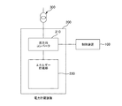
電力貯蔵装置200は、電力系統400と連系し、電力系統400から得た電力エネルギーを蓄積し取り出すことが可能な装置である。電力貯蔵装置200は、例えば蓄電池やフライホイール、キャパシタなど、様々な方式の装置によって構成することができる。電力貯蔵装置200の構成を図2に示す。
== Power storage device ==
The
電力貯蔵装置200は、双方向コンバータ210及びエネルギー貯蔵部220を有して構成される。
The
エネルギー貯蔵部220は、電力系統400から取得した電気エネルギーを、元の電気エネルギーに復元可能な状態で貯蔵する装置である。エネルギー貯蔵部220は、ナトリウム硫黄電池、鉛電池、レドックスフロー電池などの各種の化学反応を利用した電池により構成することができる。あるいはエネルギー貯蔵部220は電気二重層キャパシタにより構成することができる。またあるいは、エネルギー貯蔵部220は電力エネルギーを回転エネルギーの形で貯蔵可能なフライホイールにより構成することができる。
The
双方向コンバータ210は、電力系統400とエネルギー貯蔵部220との間でエネルギーの変換及び授受を行う。双方向コンバータ210は、後述する制御装置100からの指令(有効電力の指令値、無効電力の指令値)に従って、指定された量の有効電力及び無効電力を出力する。
有効電力の指令値及び無効電力の指令値が正の値である場合には、本実施形態に係る双方向コンバータ210は、電力貯蔵装置200から電力系統400に対して有効電力及び無効電力を供給するように動作し、有効電力の指令値及び無効電力の指令値が負の値である場合には、電力系統400から電力貯蔵装置200に有効電力及び無効電力を取り込むように動作する。
When the command value of active power and the command value of reactive power are positive values,
変圧器300は、母線420(n3)と電力貯蔵装置200との間の電圧を変換する。
==制御装置==
本実施形態に係る制御装置100は、電力系統400における電力の状態に応じて変動する第1物理量(例えば周波数)と、第2物理量(例えば電圧)と、をそれぞれ所定の目標値(第1目標値、第2目標値)に制御するべく、電力貯蔵装置200から出力する有効電力及び無効電力を制御する情報処理装置である。
== Control device ==
The
本実施形態に係る制御装置100の全体構成を図3及び図4に示す。図3は、制御装置100の機能構成を説明するための図であり、図4は、制御装置100のハードウェア構成を説明するための図である。
3 and 4 show the overall configuration of the
<ハードウェア構成>
図4に示すように、本実施形態に係る制御装置100は、CPU(Central Processing Unit)110、メモリ120、通信装置130、記憶装置140、入力装置150、出力装置160及び記録媒体読取装置170を有して構成されるコンピュータである。
<Hardware configuration>
As shown in FIG. 4, the
CPU110は制御装置100の全体の制御を司るもので、記憶装置140に記憶される本実施形態に係る各種の動作を行うためのコードから構成される制御プログラム600をメモリ120に読み出して実行することにより、制御装置100としての各種機能を実現する。
The
例えば、詳細は後述するが、CPU110により制御プログラム600が実行され、メモリ120や通信装置130、記憶装置140等のハードウェア機器と協働することにより、図3に示した計測値取得部101(第1計測値取得部101a、第2計測値取得部101b)、演算部102(有効電力算出部102a、無効電力算出部102b、有効電力補正部102c、無効電力補正部102d、第1指令値算出部102e、第2指令値算出部102f、第1差分算出部107a、第2差分算出部107b)、記憶部103、予測値算出部105(第1予測値算出部105a、第2予測値算出部105b)、指令値出力部106などが実現される。
For example, although details will be described later, the
メモリ120は例えば半導体記憶装置により構成することができる。
The
通信装置130は、ネットワークカードなどのネットワークインタフェースである。通信装置130は、インターネットやLAN(Local Area Network)などのネットワークを介して他のコンピュータからデータを受信し、受信したデータを記憶装置140やメモリ120に記憶する。また通信装置130は、記憶装置140やメモリ120に記憶されているデータを、ネットワークを介して他のコンピュータへ送信する。
The
入力装置150は、操作スイッチやキーボード、マウス、マイク等の装置であり、制御装置100の操作者による情報の入力を受け付けるための装置である。出力装置160は、LCD(Liquid Crystal Display)や表示ランプ、各種表示メータ、プリンタ、スピーカ等の装置であり、情報を出力するための装置である。
The
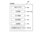
記憶装置140は、例えばハードディスク装置や半導体記憶装置等により構成することができる。記憶装置140は、各種プログラムやデータ、テーブル等を記憶するための記憶領域を提供する装置である。図5に、記憶装置140に制御プログラム600、伝達関数700〜709、第1目標値710、第2目標値720、系統情報730、伝達関数切り替えテーブル750、751等が記憶されている様子を示す。
The
なお、制御プログラム600や伝達関数700〜709、第1目標値710、第2目標値720、系統情報730、伝達関数切り替えテーブル750、751は、記録媒体読取装置170を用いて、記録媒体(各種の光ディスクや磁気ディスク、半導体メモリ等)800から記憶装置140に読み出すことで、制御装置100に格納されるようにすることもできるし、入力装置150から、あるいは通信装置130を介して通信可能に接続される他のコンピュータから取得することで、制御装置100に格納されるようにすることもできる。
Note that the
伝達関数700〜709は、制御装置100が電力貯蔵装置200に対して出力する有効電力の指令値及び無効電力の指令値を算出する際に使用する関数である。なお本実施形態に係る伝達関数700〜709は、与えられたデータの値から目的とするデータの値を算出することが可能なデータ変換要素であり、複素数領域で定義される数式に限られず、実時間領域で定義される数式であってもよいし、データテーブルやリストが含まれていても良い。
The
第1目標値710は、電力系統400における周波数(第1物理量)の目標値である。
The
第2目標値720は、電力系統400における電圧(第2物理量)の目標値である。
The
系統情報730は、例えば、電力系統400における送配電線430の長さや線路インピーダンス、負荷440の位置や有効電力及び無効電力、発電設備410の位置や出力電力等を含む、電力系統400に関するデータである。
The
伝達関数切り替えテーブル750、751は、制御装置100が、後述する有効電力の補正値及び無効電力の補正値を算出する際に用いる伝達関数を切り替える際に参照されるテーブルである。
The transfer function switching tables 750 and 751 are tables that are referred to when the
伝達関数切り替えテーブル750には、図9に示すように、時間帯ごとに、制御装置100がその時間帯に使用するべき伝達関数が対応付けて記憶されている。
In the transfer function switching table 750, as shown in FIG. 9, transfer functions to be used in the time zone by the
一方、伝達関数切り替えテーブル751には、図11に示すように、計測器450によって計測された電力の状態を表す計測値の範囲ごとに、制御装置100が使用するべき伝達関数が対応付けて記憶されている。
On the other hand, in the transfer function switching table 751, as shown in FIG. 11, a transfer function to be used by the
<ブロック線図>
次に図6を参照しながら、本実施形態に係る制御装置100が、電力貯蔵装置200に対して出力する有効電力の指令値及び無効電力の指令値を求めるために用いるブロック線図について説明する。
<Block diagram>
Next, referring to FIG. 6, a block diagram used by the
なお図6に示すブロック線図は、電力系統400、電力貯蔵装置200及び制御装置100からなる制御モデルを表したものである。そして制御装置100は、記憶装置140に記憶されている伝達関数700〜709や第1目標値710、第2目標値720、系統情報730、伝達関数切り替えテーブル750、751等のデータを用いながら制御プログラム600を実行することによってこの制御モデルに従う各種の演算を行ない、電力貯蔵装置200に対して出力する有効電力の指令値及び無効電力の指令値を算出する。
The block diagram illustrated in FIG. 6 represents a control model including the
図6において、制御装置100が電力貯蔵装置200に対して出力する有効電力の指令値及び無効電力の指令値は、それぞれPr及びQrで示されている。
In FIG. 6, the command value of active power and the command value of reactive power output from the
そしてこれらの有効電力の指令値Pr及び無効電力の指令値Qrに応じて、電力貯蔵装置200は、電力系統400に対してPb及びQbで示される有効電力及び無効電力を出力する。そしてこれによって、電力系統400の周波数(第1物理量)はF’になり、電圧(第2物理量)はV’になる。
The
なお本実施形態に係る電力貯蔵装置200は、有効電力の指令値Prに等しい有効電力Pbを出力し、無効電力の指令値Qrに等しい無効電力Qbを出力するものとしている。
The
電力系統400は、第5伝達関数705(G11)、第6伝達関数706(G12)、第7伝達関数707(G22)、第8伝達関数708(G21)、第1予測値算出部105a、第2予測値算出部105bによって表される。
The
第5伝達関数705(G11)は、電力貯蔵装置200が有効電力の指令値Prに応じた有効電力Pbを出力することにより見込まれる電力系統400の周波数(第1物理量)の計算値を算出可能な関数である。
The fifth transfer function 705 (G11) can calculate a calculated value of the frequency (first physical quantity) of the
第6伝達関数706(G12)は、電力貯蔵装置200が無効電力の指令値Qrに応じた無効電力Qbを出力することにより生じることが見込まれる電力系統400の周波数(第1物理量)の変動量を算出可能な関数である。
The sixth transfer function 706 (G12) is a fluctuation amount of the frequency (first physical quantity) of the
第1予測値算出部105aは、上記周波数の計算値を上記周波数の変動量によって補正(本実施形態では加算)して、電力系統400の周波数の予測値F’を算出する。
The first predicted
第7伝達関数707(G22)は、電力貯蔵装置200が無効電力の指令値Qrに応じた無効電力Qbを出力することにより見込まれる電力系統400の電圧(第2物理量)の計算値を算出可能な関数である。
The seventh transfer function 707 (G22) can calculate a calculated value of the voltage (second physical quantity) of the
第8伝達関数708(G21)は、電力貯蔵装置200が有効電力の指令値Prに応じた有効電力Pbを出力することにより生じることが見込まれる電力系統400の電圧(第2物理量)の変動量を算出可能な関数である。
The eighth transfer function 708 (G21) is a fluctuation amount of the voltage (second physical quantity) of the
第2予測値算出部105bは、上記電圧の計算値を上記電圧の変動量によって補正(本実施形態では加算)して、電力系統400の電圧の予測値V’を算出する。
The second predicted
このように、電力系統400は、電力貯蔵装置200から有効電力Pbが出力されると、電力系統400の周波数が変動するのみならず電圧も変動し、電力貯蔵装置200から無効電力Qbが出力されると、電力系統400の電圧が変動するのみならず周波数も変動する。
As described above, when the active power Pb is output from the
つまり、電力系統400において、周波数を制御しようとして電力貯蔵装置200から出力される有効電力Pbを制御すると電力系統400の電圧も影響を受けて変動し、電圧を制御しようとして電力貯蔵装置200から出力される無効電力Qbを制御すると電力系統400の周波数も影響を受けて変動する。
That is, in the
本実施形態に係る制御装置100は、このような干渉を取り去るために、以下に記載する第3伝達関数703(C1)及び第4伝達関数704(C2)を用いて、電力貯蔵装置200が出力すべき有効電力の指令値Pr及び無効電力の指令値Qrを算出している。これにより、電力系統400の周波数や潮流、電圧等の複数種類の物理量をより正確に制御することが可能になる。
In order to remove such interference, the
具体的に説明すると、まず、制御装置100のブロック線図は、第1差分算出部107a、第2差分算出部107b、第1伝達関数701(K1)、第2伝達関数702(K2)、第3伝達関数703(C1)、第4伝達関数704(C2)、第1指令値算出部102e、第2指令値算出部102fにより表される。
Specifically, first, the block diagram of the
第1差分算出部107aは、電力系統400における周波数の計測値Fと、目標周波数(第1目標値)710との差分ΔFを算出する。
The first
また第2差分算出部107bは、電力系統400における電圧の計測値Vと、目標電圧(第2目標値)720との差分ΔVを算出する。
The second
第1伝達関数701(K1)は、周波数の差分ΔFから、電力貯蔵装置200が出力すべき有効電力の目標値である有効電力目標値を算出する関数である。
The first transfer function 701 (K1) is a function that calculates an active power target value that is a target value of active power that the
第2伝達関数702(K2)は、電圧の差分ΔVから、電力貯蔵装置200が出力すべき無効電力の目標値である無効電力目標値を算出する関数である。
The second transfer function 702 (K2) is a function that calculates a reactive power target value that is a target value of reactive power that the
第1伝達関数701(K1)及び第2伝達関数702(K2)は、例えば記憶装置140に記憶されている系統情報730を用いて設計される。
The first transfer function 701 (K1) and the second transfer function 702 (K2) are designed using the
第3伝達関数703(C1)は、電力系統400の周波数を有効電力Pbによって制御する場合における無効電力Qbからの干渉を取り除くための関数である。具体的には、第3伝達関数703(C1)は、第2伝達関数702(K2)によって算出された無効電力目標値を用いて、第1伝達関数701(K1)によって算出された有効電力目標値に対する補正量である有効電力補正値を算出する。
The third transfer function 703 (C1) is a function for removing interference from the reactive power Qb when the frequency of the
第4伝達関数704(C2)は、上記電力系統400の電圧を無効電力Qbによって制御する場合における有効電力Pbからの干渉を取り除くための関数である。具体的には、第4伝達関数704(C2)は、第1伝達関数701(K1)によって算出された有効電力目標値を用いて、第2伝達関数702(K2)によって算出された無効電力目標値に対する補正量である無効電力補正値を算出する。
The fourth transfer function 704 (C2) is a function for removing interference from the active power Pb when the voltage of the
第1指令値算出部102eは、有効電力目標値を有効電力補正値によって補正(本実施形態では加算)して、電力貯蔵装置200に対する有効電力の指令値Prを算出する。
The first command
第2指令値算出部102fは、無効電力目標値を無効電力補正値によって補正(本実施形態では加算)して、電力貯蔵装置200に対する無効電力の指令値Qrを算出する。
The second command
そして制御装置100は、電力貯蔵装置200に対して出力すべき有効電力の指令値Pr及び無効電力Qrの指令値を算出する。
Then, the
このように、本実施形態に係る制御装置100は、第1伝達関数701〜第4伝達関数704を用いて有効電力の指令値Pr及び無効電力Qrの指令値を算出するようにしているため、電直貯蔵装置200や電力系統400の特性が変化した場合であっても、第1伝達関数701〜第4伝達関数704を変更することによって、迅速かつ柔軟に対応することができ、電力系統400の目標周波数や目標電圧を維持するように制御を続けることができる。
As described above, the
次に、上記干渉を取り除くための第3伝達関数703(C1)及び第4伝達関数704(C2)について具体的に説明する。 Next, the third transfer function 703 (C1) and the fourth transfer function 704 (C2) for removing the interference will be specifically described.
まず、図3に示すブロック線図から、以下の(式1)〜(式6)が成り立つ。 First, the following (Formula 1) to (Formula 6) hold from the block diagram shown in FIG.
Pr=(K1×ΔF)+(C1×K2×ΔV) …(式1)
Qr=(C2×K1×ΔF)+(K2×ΔV) …(式2)
F’=(G11×Pb)+(G12×Qb) …(式3)
V’=(G21×Pb)+(G22×Qb) …(式4)
Pb=Pr …(式5)
Qb=Qr …(式6)
(式1)〜(式6)からPr、Pb、Qr、Qbを消去すると、(式7)〜(式8)が得られる。
Pr = (K1 × ΔF) + (C1 × K2 × ΔV) (Formula 1)
Qr = (C2 × K1 × ΔF) + (K2 × ΔV) (Formula 2)
F ′ = (G11 × Pb) + (G12 × Qb) (Formula 3)
V ′ = (G21 × Pb) + (G22 × Qb) (Formula 4)
Pb = Pr (Formula 5)
Qb = Qr (Formula 6)
When Pr, Pb, Qr, and Qb are deleted from (Expression 1) to (Expression 6), (Expression 7) to (Expression 8) are obtained.
F’=(G11+G12×C2)×(K1×ΔF)+(G11×C1+G12)×(K2×ΔV) …(式7)
V’=(G21+G22×C2)×(K1×ΔF)+(G21×C1+G22)×(K2×ΔV) …(式8)
干渉がなくなるためには(式9)〜(式10)が成り立つ必要がある。そして(式9)〜(式10)をC1、C2について解くことにより、C1及びC2を(式11)〜(式12)のように求めることができる。
F ′ = (G11 + G12 × C2) × (K1 × ΔF) + (G11 × C1 + G12) × (K2 × ΔV) (Expression 7)
V ′ = (G21 + G22 × C2) × (K1 × ΔF) + (G21 × C1 + G22) × (K2 × ΔV) (Equation 8)
In order to eliminate the interference, (Expression 9) to (Expression 10) must be satisfied. Then, by solving (Equation 9) to (Equation 10) for C1 and C2, C1 and C2 can be obtained as (Equation 11) to (Equation 12).
(G11×C1+G12)=0 …(式9)
(G21+G22×C2)=0 …(式10)
C1=-G12/G11 …(式11)
C2=-G21/G22 …(式12)
つまり、第3伝達関数703(C1)及び第4伝達関数704(C2)は、電力系統400の伝達関数である第5伝達関数705(G11)〜第8伝達関数708(G21)を求めることにより、確定させることができる。
(G11 × C1 + G12) = 0 ... (Formula 9)
(G21 + G22 × C2) = 0 ... (Formula 10)
C1 = -G12 / G11 (Formula 11)
C2 = -G21 / G22 (Formula 12)
That is, the third transfer function 703 (C1) and the fourth transfer function 704 (C2) are obtained by obtaining the fifth transfer function 705 (G11) to the eighth transfer function 708 (G21) which are transfer functions of the
なお、第5伝達関数705(G11)〜第8伝達関数708(G21)は、例えば既知のシステム同定技術を用いることによって求めることが可能である。 The fifth transfer function 705 (G11) to the eighth transfer function 708 (G21) can be obtained by using a known system identification technique, for example.
例えば、第5伝達関数705(G11)及び第6伝達関数706(G12)をシステム同定技術を用いて求める場合には、過去の所定期間(例えば1か月間)における電力系統400の周波数の計測値Fと、有効電力の指令値Prと無効電力の指令値Qrとを用いて、これらのデータの間に成り立つ関係式を第5伝達関数705(G11)及び第6伝達関数706(G12)として特定する。
For example, when the fifth transfer function 705 (G11) and the sixth transfer function 706 (G12) are obtained using the system identification technique, the measured value of the frequency of the
つまり、周波数の計測値Fを目的変数とし、有効電力の指令値Pr及び無効電力の指令値Qrを説明変数とし、第5伝達関数705(G11)と第6伝達関数706(G12)との和を回帰式とした回帰分析を行うことによって、第5伝達関数705(G11)と第6伝達関数706(G12)の制御パラメータを決定する。 That is, the frequency measurement value F is an objective variable, the active power command value Pr and the reactive power command value Qr are explanatory variables, and the sum of the fifth transfer function 705 (G11) and the sixth transfer function 706 (G12). By performing regression analysis using the regression equation, control parameters for the fifth transfer function 705 (G11) and the sixth transfer function 706 (G12) are determined.
同様に、第7伝達関数707(G22)及び第8伝達関数708(G21)をシステム同定技術を用いて求める場合には、電圧の計測値Vを目的変数とし、有効電力の指令値Pr及び無効電力の指令値Qrを説明変数とし、第7伝達関数707(G22)と第8伝達関数708(G21)との和を回帰式とした回帰分析を行うことによって、第7伝達関数707(G22)と第8伝達関数708(G21)の制御パラメータを決定する。 Similarly, when the seventh transfer function 707 (G22) and the eighth transfer function 708 (G21) are obtained using the system identification technique, the measured value V of the voltage is an objective variable, the command value Pr of the active power and the invalid value The seventh transfer function 707 (G22) is performed by performing regression analysis using the command value Qr of power as an explanatory variable and the sum of the seventh transfer function 707 (G22) and the eighth transfer function 708 (G21) as a regression equation. And the control parameter of the eighth transfer function 708 (G21).
本実施形態に係る制御装置100は、このようにして定めた第3伝達関数703(C1)及び第4伝達関数704(C2)を制御モデルに組み込むことによって、電力貯蔵装置200が出力すべき有効電力の指令値Pr及び無効電力の指令値Qrを算出している。このため、電力貯蔵装置200が有効電力Pb及び無効電力Qbを出力する際に電力系統400の周波数や潮流、電圧に生ずる干渉を取り去ることが可能となり、電力系統400の周波数や潮流、電圧等の複数種類の物理量をより正確に制御することを可能にしている。
The
ところで、電力系統400の伝達関数である第5伝達関数705(G11)〜第8伝達関数708(G21)は、電力系統400における電力の状態に応じて変動する。
By the way, the fifth transfer function 705 (G11) to the eighth transfer function 708 (G21), which are transfer functions of the
例えば電力系統400における負荷440の電力消費量が図13に示すように変動する場合、時刻t1とt2とでは、電力系統400の周波数に対する応答特性や潮流に対する応答特性、電圧に対する応答特性はそれぞれ異なるため、時刻t1とt2とのそれぞれにおいて、電力貯蔵装置200から同量の有効電力Pb及び同量の無効電力Qbを出力した場合であっても、電力系統400の周波数や潮流、電圧は異なる値に変動する。
For example, when the power consumption of the
また電力系統400の特性は、負荷440の電力消費量の違いだけでなく、電力系統400を構成する制御機器の動作状況の違いや、太陽光発電や風力発電等の発電量の違いなどによっても異なってくる。
The characteristics of the
そこで本実施形態に係る制御装置100は、第3伝達関数703(C1)及び第4伝達関数704(C2)を、電力系統400における電力の状態に応じて定まる所定のタイミングで切り替えるようにしている。
Therefore, the
例えば電力系統400の特性が1日の間で第1状態と第2状態とを毎日繰り返すように規則的に変化する場合には、例えば電力系統400が第1状態になる昼間の時間帯(6時から18時まで)と、第2状態になる夜間の時間帯(18時から6時)に区分して、それぞれの時間帯に適した特性をもった伝達関数を用いるようにする。
For example, when the characteristics of the
例えば昼間の時間帯における電力系統400の特性が、G11、G12、G21、G22で表され、夜間の時間帯における電力系統400の特性が、G11’、G12’、G21’、G22’で表される場合、昼間の時間帯には、(式11)(式12)で表される第3伝達関数703(C1)及び第4伝達関数704(C2)を用いて有効電力の補正値及び無効電力の補正値を算出するようにし、夜間の時間帯には、(式13)(式14)で表される第3伝達関数703(C1’)及び第4伝達関数704(C2’)を用いて有効電力の補正値及び無効電力の補正値を算出するようにする。
For example, the characteristics of the
C1'=-G12'/G11' …(式13)
C2'=-G21'/G22' …(式14)
このような態様によって、電力系統400の周波数や潮流、電圧等の複数種類の物理量をより正確に制御することが可能になる。
C1 '=-G12' / G11 '(Formula 13)
C2 '=-G21' / G22 '(Formula 14)
Such an aspect makes it possible to more accurately control a plurality of types of physical quantities such as the frequency, power flow, and voltage of the
このように、電力系統400の特性が規則的に変化する場合には、この規則性を利用して事前に定めた所定のタイミング(毎日の特定の時刻、あるいは毎月の特定の日、あるいは毎年の特定の月など)で、第3伝達関数703及び第4伝達関数704を切り替えるようにするとよい。
As described above, when the characteristics of the
なお、制御装置100は、第3伝達関数703及び第4伝達関数704を切り替えるだけでなく、広く、有効電力の補正値及び無効電力の補正値を算出する際に用いる制御データを切り替えるようにできる。このような制御データとしては、例えば上記の(式11)〜(式14)で示されるような第3伝達関数703や第4伝達関数704が含まれるだけでなく、第1目標値710、第2目標値720、系統情報730、各種の係数、制御パラメータ、テーブル、さらにはブロック線図も含まれてよい。
Note that the
ブロック線図を切り替える場合の例としては、例えば、昼間の時間帯には、有効電力の目標値及び無効電力の目標値を、それぞれ第3伝達関数703及び第4伝達関数704により算出された補正値で補正するが、夜間の時間帯には、いずれか一方あるいは両方の補正を行わないように切り替えるような例が挙げられる。
As an example of switching the block diagram, for example, during the daytime hours, corrections are made by calculating the target value of the active power and the target value of the reactive power by the
このように、本実施形態に係る制御装置100によれば、電力貯蔵装置200の制御を電力系統400の特性の変化に応じて柔軟に行うことが可能となる。そしてこれにより、電力系統400の周波数や潮流、電圧等の複数種類の物理量をより正確に制御することが可能になる。
Thus, according to the
また、有効電力の補正値及び無効電力の補正値を算出する際に用いる制御データを切り替えるタイミングは、電力系統400における電力の状態に応じて定まる所定のタイミングであればよく、上記のように事前に定められた特定の時刻(6時、18時等)である場合に限らず、電力系統400に設置される計測器450によって計測された電力系統400の電力の状態を表す計測値と判定値との比較の結果に応じて、切り替えを行うタイミングを動的に決定するようにしてもよい。
In addition, the timing for switching the control data used when calculating the correction value for the active power and the correction value for the reactive power may be a predetermined timing determined according to the power state in the
動的にタイミングを決定する場合は、例えば、電力系統400の周波数や負荷端電圧の値の組み合わせが異なる複数の制御モデルについて、それぞれ第3伝達関数703及び第4伝達関数704を事前に求めて伝達関数切り替えテーブル451に記憶しておき、計測器450によって随時計測される周波数や負荷端電圧の計測値をそれぞれ判定値と比較することによって、該当する第3伝達関数703及び第4伝達関数704に切り替えるようにする。
When dynamically determining the timing, for example, the
このような態様によれば、電力貯蔵装置200の制御を電力系統400の特性の変化に応じてより一層柔軟に行うことが可能となる。そしてこれにより、電力系統400の周波数や潮流、電圧等の複数種類の物理量をより一層正確に制御することが可能になる。
According to such an aspect, the
<電力貯蔵装置の制御機能>
次に、図3及び図6〜図7等を参照しながら、本実施形態に係る制御装置100が有する電力貯蔵装置200の制御機能及び動作について説明する。
<Control function of power storage device>
Next, the control function and operation of the
図3に示すように、制御装置100は、計測値取得部101、演算部102および指令値出力部106を有して構成される。
As shown in FIG. 3, the
そして演算部102には、第1差分算出部107a、第2差分算出部107b、有効電力算出部102a、無効電力算出部102b、有効電力補正部102c、無効電力補正部102d、第1指令値算出部102e、第2指令値算出部102fが含まれる。
The
なお有効電力算出部102aには、第1伝達関数701(K1)が含まれる。また無効電力算出部102bには第2伝達関数702(K2)が含まれる。有効電力補正部102cには第3伝達関数703(C1)が含まれる。無効電力補正部102dには第4伝達関数704(C2)が含まれる。
The active
計測値取得部101は、計測器450によって計測された電力系統400における周波数(第1物理量)の計測値Fと、電圧(第2物理量)の計測値Vを取得する。
The measurement
具体的には、計測値取得部101は、第1計測値取得部101aと第2計測値取得部101bとを有し、第1計測値取得部101aは電力系統400における周波数(第1物理量)の計測値Fを取得し、第2計測値取得部101bは電力系統400における電圧(第2物理量)の計測値Vを取得する。
Specifically, the measurement
そして第1差分算出部107aは、周波数の計測値Fと、目標周波数(第1目標値)710との差分ΔFを算出する。
Then, the first
また第2差分算出部107bは、電圧の計測値Vと、目標電圧(第2目標値)720との差分ΔVを算出する。
The second
そして有効電力算出部102aは、第1伝達関数701(K1)を用いて、上記周波数の差分ΔFから、電力貯蔵装置200が出力すべき有効電力の目標値である有効電力目標値を算出する。電力貯蔵装置200が有効電力目標値に応じた有効電力を出力することによって、電力系統400の周波数を第1目標値710に近づけることができる。
Then, the active
一方、無効電力算出部102bは、第2伝達関数702(K2)を用いて、上記電圧の差分ΔVから、電力貯蔵装置200が出力すべき無効電力の目標値である無効電力目標値を算出する。電力貯蔵装置200が無効電力目標値に応じた有効電力を出力することによって、電力系統400の電圧を第2目標値720に近づけることができる。
On the other hand, the reactive
ただし上述したように、電力系統400の周波数は、電力貯蔵装置200が出力する有効電力によって変動するだけでなく、電力貯蔵装置200が無効電力を出力することによっても影響を受けて変動する。
However, as described above, the frequency of the
同様に、電力系統400の電圧は、電力貯蔵装置200が出力する無効電力によって変動するだけでなく、電力貯蔵装置200が有効電力を出力することによっても影響を受けて変動する。
Similarly, the voltage of the
このため、本実施形態に係る制御装置100は、有効電力算出部102aが算出した有効電力目標値を、別途、有効電力補正部102cによって算出された有効電力補正値によって補正した後に、電力貯蔵装置200に対して有効電力指令値Prとして出力する。
Therefore, the
同様に、制御装置100は、無効電力算出部102bが算出した無効電力目標値を、別途、無効電力補正部102dによって算出された無効電力補正値によって補正した後に、電力貯蔵装置200に対して、無効電力指令値Qrとして出力する。
Similarly, the
有効電力補正部102cは、上述したように、有効電力算出部102aが算出した有効電力目標値に対する補正量である有効電力補正値を算出する。具体的には、有効電力補正部102cは、第3伝達関数703を用いて、無効電力算出部102bが算出した無効電力目標値から有効電力補正値を算出する。このようにして、電力貯蔵装置200が無効電力を出力することにより生ずる電力系統400の周波数の変動を相殺することが可能となる。
As described above, the active
同様に、無効電力補正部102dは、無効電力算出部102bが算出した無効電力目標値に対する補正量である無効電力補正値を算出する。具体的には、無効電力補正部102dは、第4伝達関数704を用いて、有効電力算出部102aが算出した有効電力目標値から無効電力補正値を算出する。このようにして、電力貯蔵装置200が有効電力を出力することにより生ずる電力系統400の電圧の変動を相殺することが可能となる。
Similarly, the reactive
第1指令値算出部102eは、有効電力目標値を有効電力補正値によって補正(本実施形態では加算)して、電力貯蔵装置200に対する有効電力の指令値Prを算出する。
The first command
第2指令値算出部102fは、無効電力目標値を無効電力補正値によって補正(本実施形態では加算)して、電力貯蔵装置200に対する無効電力の指令値Qrを算出する。
The second command
そして図3に示す指令値出力部106は、このようにして算出された有効電力の指令値Pr及び無効電力の指令値Qrを、電力貯蔵装置200に出力する。
The command
本実施形態に係る制御装置100は、このようにして定めた有効電力補正部102c、無効電力補正部102dを用いて、電力貯蔵装置200が出力すべき有効電力の指令値Pr及び無効電力の指令値Qrを算出している。このため、電力貯蔵装置200が有効電力Pb及び無効電力Qbを出力する際に電力系統400の周波数や潮流、電圧に生ずる干渉を取り去ることが可能となり、電力系統400の周波数や潮流、電圧等の複数種類の物理量をより正確に制御することを可能にしている。
The
なお計測値取得部101は、所定期間毎に(例えば1時間毎に)、周波数の計測値Fと電圧の計測値Vを取得しているが、本実施形態に係る制御装置100は、計測値取得部101がこれらの計測値を取得する毎に、有効電力の指令値Pr及び無効電力の指令値Qrを新たに算出して、電力貯蔵装置200に出力している。
The measurement
このような態様によって、電力系統400における電力の最新の状態に応じて、電力貯蔵装置200に対して最適な有効電力の指令値Pr及び無効電力の指令値Qrを継続的に出力することが可能になる。
According to such an aspect, it is possible to continuously output the optimum active power command value Pr and reactive power command value Qr to the
なお、もちろん、制御装置100が有効電力の指令値Pr及び無効電力の指令値Qrを算出するタイミングは、周波数の計測値Fと電圧の計測値Vを取得するタイミングと同じでなくてもよい。
Of course, the timing at which the
次に本実施形態に係る制御装置100の制御方法について図7のフローチャート参照しながら説明する。
Next, a control method of the
まず、計測値取得部101は、計測器450によって計測された電力系統400における周波数(第1物理量)の計測値Fと、電圧(第2物理量)の計測値Vを取得する(S1000)。
First, the measured
そして有効電力算出部102aは、第1伝達関数701(K1)を用いて、周波数の計測値Fと目標周波数(第1目標値)710との差分ΔFから、電力貯蔵装置200が出力すべき有効電力の目標値である有効電力目標値を算出する。同様に無効電力算出部102bは、第2伝達関数702(K2)を用いて、電圧の計測値Vと、目標電圧(第2目標値)720との差分ΔVから、電力貯蔵装置200が出力すべき無効電力の目標値である無効電力目標値を算出する(S1010)。
Then, the active
そして有効電力補正部102cは、第3伝達関数703を用いて、無効電力算出部102bによって算出された無効電力目標値から有効電力補正値を算出する。同様に、無効電力補正部102dは、第4伝達関数704を用いて、有効電力算出部102aによって算出された有効電力目標値から無効電力補正値を算出する(S1020)。
Then, the active
そして第1指令値算出部102eは、有効電力目標値を有効電力補正値によって補正(本実施形態では加算)して、電力貯蔵装置200に対する有効電力の指令値Prを算出する。同様に、第2指令値算出部102fは、無効電力目標値を無効電力補正値によって補正(本実施形態では加算)して、電力貯蔵装置200に対する無効電力の指令値Qrを算出する(S1030)。
Then, the first command
そして指令値出力部106は、有効電力の指令値Pr及び無効電力の指令値Qrを、電力貯蔵装置200に出力する(S1040)。
Then, the command
このような方法で制御装置100を制御することによって、電力貯蔵装置200が有効電力Pb及び無効電力Qbを出力する際に電力系統400の周波数や潮流、電圧に生ずる干渉を取り去ることが可能となり、電力系統400の周波数や潮流、電圧等の複数種類の物理量をより正確に制御することが可能になる。
By controlling the
<伝達関数の切り替え機能>
次に、図3、図6、図8〜図11等を参照しながら、本実施形態に係る制御装置100が有する伝達関数の切り替え機能及び動作について説明する。
<Transfer function switching function>
Next, the transfer function switching function and operation of the
まず本実施形態に係る制御装置100が、事前に定められた所定のタイミング(時刻、日にち、月、曜日など)が到来したときに、第3伝達関数703及び第4伝達関数704を切り替える場合について説明する。
First, when the
図8に示すように、有効電力補正部102c及び無効電力補正部102dは、切り替え時刻が到来するのをチェックしている(S2000)。
As shown in FIG. 8, the active
そして切り替え時刻が到来したら、有効電力補正部102c及び無効電力補正部102dは、図9に示す伝達関数切り替えテーブル750を参照し、該当する時間帯の伝達関数に第3伝達関数703及び第4伝達関数704を切り替える(S2010)。
When the switching time arrives, the active
このような態様によれば、電力貯蔵装置200の制御を、電力系統400の特性の変化に応じて柔軟に行うことが可能となる。そしてこれにより、電力系統400の周波数や潮流、電圧等の複数種類の物理量をより正確に制御することが可能になる。
According to such an aspect, control of the
次に、本実施形態に係る制御装置100が動的なタイミングで第3伝達関数703及び第4伝達関数704を切り替える場合について説明する。
Next, a case where the
図10に示すように、計測値取得部101は、第3伝達関数703及び第4伝達関数704を切り替えるか否かを判定するために定められた電力系統400における物理量の計測値を取得する(S3000)。このような物理量としては、例えば電力系統400における周波数や負荷端電圧の計測値などを用いることができる。
As illustrated in FIG. 10, the measurement
そして有効電力補正部102c及び無効電力補正部102dは、図11に示す伝達関数切り替えテーブル751を参照し、取得した計測値に該当する第3伝達関数703及び第4伝達関数704に切り替える(S3010)。
Then, the active
このような態様により、電力貯蔵装置200の制御を電力系統400の特性の変化に応じてより一層柔軟に行うことが可能となる。そしてこれにより、電力系統400の周波数や潮流、電圧等の複数種類の物理量をより一層正確に制御することが可能になる。
By such an aspect, it becomes possible to control the
==他の実施形態==
制御装置100は、図12に示すブロック線図によって、電力貯蔵装置200に対して出力する有効電力の指令値及び無効電力の指令値を算出するようにしてもよい。
== Other Embodiments ==
The
図12に示すブロック線図は、図6に示したブロック線図に対して、第9伝達関数740(D1)及び第10伝達関数741(D2)が追加されている。 In the block diagram shown in FIG. 12, a ninth transfer function 740 (D1) and a tenth transfer function 741 (D2) are added to the block diagram shown in FIG.
第9伝達関数740(D1)は、有効電力に対応した変動対応コントローラとして機能する。また第10伝達関数741(D2)は、無効電力に対応した変動対応コントローラとして機能する。 The ninth transfer function 740 (D1) functions as a fluctuation corresponding controller corresponding to the active power. In addition, the tenth transfer function 741 (D2) functions as a fluctuation corresponding controller corresponding to reactive power.
第9伝達関数740(D1)及び第10伝達関数741(D2)は、第1伝達関数701(K1)や第2伝達関数702(K2)と同様に、例えば記憶装置140に記憶されている系統情報730を用いて設計される。
Similarly to the first transfer function 701 (K1) and the second transfer function 702 (K2), the ninth transfer function 740 (D1) and the tenth transfer function 741 (D2) are stored in the
そしてこの場合、電力貯蔵装置200が出力すべき有効電力の目標値である有効電力目標値は、周波数の差分ΔFを、第1伝達関数701(K1)と第9伝達関数740(D1)で演算することで算出される。また無効電力目標値は、電圧の差分ΔVを、第2伝達関数702(K2)と第10伝達関数741(D2)で演算することで算出される。
In this case, the active power target value, which is the target value of the active power to be output by the
そして第1指令値算出部102eは、この有効電力目標値を、第3伝達関数703(C1)によって算出された有効電力補正値によって補正(本実施形態では加算)して、電力貯蔵装置200に対する有効電力の指令値Prを算出する。
Then, the first command
第2指令値算出部102fは、無効電力目標値を、第4伝達関数704(C2)によって算出された無効電力補正値によって補正(本実施形態では加算)して、電力貯蔵装置200に対する無効電力の指令値Qrを算出する。
The second command
次に、図12に示すブロック線図を用いる場合の第3伝達関数703(C1)及び第4伝達関数704(C2)について具体的に説明する。 Next, the third transfer function 703 (C1) and the fourth transfer function 704 (C2) when the block diagram shown in FIG. 12 is used will be specifically described.
まず、図9に示すブロック線図から、以下の(式15)〜(式20)が成り立つ。 First, from the block diagram shown in FIG. 9, the following (Expression 15) to (Expression 20) hold.
Pr=(D1×K1×ΔF)+(C1×K2×ΔV) …(式15)
Qr=(C2×K1×ΔF)+(D2×K2×ΔV) …(式16)
F’=(G11×Pb)+(G12×Qb) …(式17)
V’=(G21×Pb)+(G22×Qb) …(式18)
Pb=Pr …(式19)
Qb=Qr …(式20)
(式15)〜(式20)からPr、Pb、Qr、Qbを消去すると、(式21)〜(式22)が得られる。
Pr = (D1 × K1 × ΔF) + (C1 × K2 × ΔV) (Formula 15)
Qr = (C2 × K1 × ΔF) + (D2 × K2 × ΔV) (Formula 16)
F ′ = (G11 × Pb) + (G12 × Qb) (Expression 17)
V ′ = (G21 × Pb) + (G22 × Qb) (Formula 18)
Pb = Pr (Formula 19)
Qb = Qr (Formula 20)
When Pr, Pb, Qr, and Qb are deleted from (Expression 15) to (Expression 20), (Expression 21) to (Expression 22) are obtained.
F’=(G11×D1+G12×C2)×(K1×ΔF)+(G11×C1+G12×D2)×(K2×ΔV) …(式21)
V’=(G21×D1+G22×C2)×(K1×ΔF)+(G21×C1+G22×D2)×(K2×ΔV) …(式22)
干渉がなくなるためには(式23)〜(式24)が成り立つ必要がある。そして(式23)〜(式24)をC1、C2について解くことにより、C1及びC2を(式25)〜(式26)のように求めることができる。
F ′ = (G11 × D1 + G12 × C2) × (K1 × ΔF) + (G11 × C1 + G12 × D2) × (K2 × ΔV) (Formula 21)
V ′ = (G21 × D1 + G22 × C2) × (K1 × ΔF) + (G21 × C1 + G22 × D2) × (K2 × ΔV) (Formula 22)
In order to eliminate interference, (Equation 23) to (Equation 24) need to hold. Then, by solving (Equation 23) to (Equation 24) for C1 and C2, C1 and C2 can be obtained as (Equation 25) to (Equation 26).
(G11×C1+G12×D2)=0 …(式23)
(G21×D1+G22×C2)=0 …(式24)
C1=-(G12×D2)/G11 …(式25)
C2=-(G21×D1)/G22 …(式26)
つまり、第3伝達関数703(C1)及び第4伝達関数704(C2)は、電力系統400の伝達関数である第5伝達関数705(G11)〜第8伝達関数708(G21)、第9伝達関数740(D1)、及び第10伝達関数741(D2)を求めることにより、確定させることができる。
(G11 × C1 + G12 × D2) = 0 (Equation 23)
(G21 × D1 + G22 × C2) = 0 (Formula 24)
C1 =-(G12 × D2) / G11 (Formula 25)
C2 =-(G21 × D1) / G22 (Formula 26)
That is, the third transfer function 703 (C1) and the fourth transfer function 704 (C2) are the fifth transfer function 705 (G11) to the eighth transfer function 708 (G21), which are transfer functions of the
本実施形態においても、第5伝達関数705(G11)〜第8伝達関数708(G21)は、上述したように、既知のシステム同定技術を用いることによって求めることが可能である。 Also in the present embodiment, the fifth transfer function 705 (G11) to the eighth transfer function 708 (G21) can be obtained by using a known system identification technique as described above.
そのため、本実施形態に係る制御装置100の場合も、このようにして定めた第3伝達関数703(C1)及び第4伝達関数704(C2)を制御モデルに組み込むことによって、電力貯蔵装置200が出力すべき有効電力の指令値Pr及び無効電力の指令値Qrを算出することができる。そして、電力貯蔵装置200が有効電力Pb及び無効電力Qbを出力する際に電力系統400の周波数や潮流、電圧に生ずる干渉を取り去ることが可能となり、電力系統400の周波数や潮流、電圧等の複数種類の物理量をより正確に制御することが可能になる。
Therefore, also in the case of the
以上説明したように、本実施形態に係る制御装置100、制御装置100の制御方法及び制御プログラム600によれば、電力系統400の周波数や潮流、電圧等の複数種類の物理量に生ずる干渉を取り除き、電力系統400をより正確に制御することが可能となる。
As described above, according to the
そしてまた、電力系統400における電力の品質維持向上や、そのための労力軽減を図ることが可能となる。
In addition, it is possible to improve and maintain the quality of power in the
なお上述した実施の形態は本発明の理解を容易にするためのものであり、本発明を限定して解釈するためのものではない。本発明はその趣旨を逸脱することなく変更、改良され得るとともに、本発明にはその等価物も含まれる。 The embodiments described above are for facilitating the understanding of the present invention, and are not intended to limit the present invention. The present invention can be changed and improved without departing from the gist thereof, and equivalents thereof are also included in the present invention.
100 制御装置
101 計測値取得部
102 演算部
103 記憶部
105 予測値算出部
106 指令値出力部
107 差分算出部
110 CPU
120 メモリ
130 通信装置
140 記憶装置
150 入力装置
160 出力装置
170 記録媒体読取装置
200 電力貯蔵装置
210 双方向コンバータ
220 エネルギー貯蔵部
300 変圧器
400 電力系統
410 発電設備
420 母線
430 送配電線
440 負荷
450 計測器
600 制御プログラム
700〜709 伝達関数
710 第1目標値
720 第2目標値
730 系統情報
740〜741 伝達関数
750、751 伝達関数切り替えテーブル
800 記録媒体
DESCRIPTION OF
120
Claims (5)
前記電力系統における第1物理量を第1目標値に制御するべく前記電力貯蔵装置が出力すべき有効電力の目標値と、前記電力系統における第2物理量を第2目標値に制御するべく前記電力貯蔵装置が出力すべき無効電力の目標値と、を算出する電力算出部と、
前記電力貯蔵装置が前記無効電力を出力することにより生ずる前記第1物理量の変動を打ち消すような前記有効電力の補正値と、前記電力貯蔵装置が前記有効電力を出力することにより生ずる前記第2物理量の変動を打ち消すような前記無効電力の補正値を算出する電力補正部と、
を備え、
前記電力補正部は、前記電力系統における電力の状態に応じて定まる所定のタイミングで、前記有効電力の補正値を算出する際に用いる制御データを第1制御データから第2制御データに切り替え、前記無効電力の補正値を算出する際に用いる制御データを第3制御データから第4制御データに切り替える
ことを特徴とする制御装置。 A control device for controlling a power storage device linked to a power system,
The active power target value to be output by the power storage device to control the first physical quantity in the power system to a first target value, and the power storage to control the second physical quantity in the power system to a second target value. A power calculation unit for calculating a target value of reactive power to be output by the device;
The correction value of the active power that cancels the fluctuation of the first physical quantity that is generated when the power storage device outputs the reactive power, and the second physical quantity that is generated when the power storage device outputs the active power. A power correction unit that calculates a correction value of the reactive power so as to cancel the fluctuation of
With
The power correction unit switches the control data used when calculating the correction value of the active power from the first control data to the second control data at a predetermined timing determined according to the state of power in the power system, A control device that switches control data used when calculating a reactive power correction value from third control data to fourth control data.
前記電力補正部は、前記電力系統における電力の状態が第1状態から第2状態に切り替わるものとして事前に定められた時刻が到来したときに、前記制御データの切り替えを行うことを特徴とする制御装置。 The control device according to claim 1,
The power correction unit performs switching of the control data when a predetermined time has arrived when the power state in the power system is switched from the first state to the second state. apparatus.
前記電力補正部は、前記電力系統に設置される計測器によって計測された前記電力系統の電力の状態を表す計測値と判定値との比較の結果に応じて、前記制御データの切り替えを行うことを特徴とする制御装置。 The control device according to claim 1,
The power correction unit performs switching of the control data according to a result of comparison between a measured value representing a power state of the power system measured by a measuring instrument installed in the power system and a determination value. A control device characterized by.
前記制御装置が、前記電力系統における第1物理量を第1目標値に制御するべく前記電力貯蔵装置が出力すべき有効電力の目標値と、前記電力系統における第2物理量を第2目標値に制御するべく前記電力貯蔵装置が出力すべき無効電力の目標値と、を算出し、
前記制御装置が、前記電力貯蔵装置が前記無効電力を出力することにより生ずる前記第1物理量の変動を打ち消すような前記有効電力の補正値と、前記電力貯蔵装置が前記有効電力を出力することにより生ずる前記第2物理量の変動を打ち消すような前記無効電力の補正値を算出し、
前記制御装置が、前記電力系統における電力の状態に応じて定まる所定のタイミングで、前記有効電力の前記補正値を算出する際に用いる制御データを第1制御データから第2制御データに切り替え、前記無効電力の前記補正値を算出する際に用いる制御データを第3制御データから第4制御データに切り替える
ことを特徴とする制御装置の制御方法。 A control method of a control device of a power storage device linked to a power system,
The control device controls the target value of the active power to be output by the power storage device to control the first physical quantity in the power system to the first target value, and the second physical quantity in the power system to the second target value. To calculate the reactive power target value to be output by the power storage device,
When the control device cancels the fluctuation of the first physical quantity caused by the power storage device outputting the reactive power, the active power correction value, and the power storage device outputs the active power. Calculating a correction value of the reactive power so as to cancel the fluctuation of the second physical quantity that occurs,
The control device switches the control data used when calculating the correction value of the active power from the first control data to the second control data at a predetermined timing determined according to the state of power in the power system, A control method for a control device, wherein control data used for calculating the correction value of reactive power is switched from third control data to fourth control data.
前記電力系統における第1物理量を第1目標値に制御するべく前記電力貯蔵装置が出力すべき有効電力の目標値と、前記電力系統における第2物理量を第2目標値に制御するべく前記電力貯蔵装置が出力すべき無効電力の目標値と、を算出する機能と、
前記電力貯蔵装置が前記無効電力を出力することにより生ずる前記第1物理量の変動を打ち消すような前記有効電力の補正値と、前記電力貯蔵装置が前記有効電力を出力することにより生ずる前記第2物理量の変動を打ち消すような前記無効電力の補正値を算出する機能と、
前記電力系統における電力の状態に応じて定まる所定のタイミングで、前記有効電力の補正値を算出する際に用いる制御データを第1制御データから第2制御データに切り替え、前記無効電力の補正値を算出する際に用いる制御データを第3制御データから第4制御データに切り替える機能と、
を実現するためのプログラム。 In the control device that controls the power storage device linked to the power system,
The active power target value to be output by the power storage device to control the first physical quantity in the power system to a first target value, and the power storage to control the second physical quantity in the power system to a second target value. A function for calculating a target value of reactive power to be output by the device;
The correction value of the active power that cancels the fluctuation of the first physical quantity that is generated when the power storage device outputs the reactive power, and the second physical quantity that is generated when the power storage device outputs the active power. A function of calculating a correction value of the reactive power so as to cancel the fluctuation of
The control data used when calculating the correction value of the active power is switched from the first control data to the second control data at a predetermined timing determined according to the state of power in the power system, and the correction value of the reactive power is changed. A function of switching control data used for calculation from the third control data to the fourth control data;
Program to realize.
Priority Applications (1)
| Application Number | Priority Date | Filing Date | Title |
|---|---|---|---|
| JP2015133544A JP6524824B2 (en) | 2015-07-02 | 2015-07-02 | Control device of power storage device, control method of control device of power storage device, and program |
Applications Claiming Priority (1)
| Application Number | Priority Date | Filing Date | Title |
|---|---|---|---|
| JP2015133544A JP6524824B2 (en) | 2015-07-02 | 2015-07-02 | Control device of power storage device, control method of control device of power storage device, and program |
Publications (2)
| Publication Number | Publication Date |
|---|---|
| JP2017017894A true JP2017017894A (en) | 2017-01-19 |
| JP6524824B2 JP6524824B2 (en) | 2019-06-05 |
Family
ID=57831251
Family Applications (1)
| Application Number | Title | Priority Date | Filing Date |
|---|---|---|---|
| JP2015133544A Active JP6524824B2 (en) | 2015-07-02 | 2015-07-02 | Control device of power storage device, control method of control device of power storage device, and program |
Country Status (1)
| Country | Link |
|---|---|
| JP (1) | JP6524824B2 (en) |
Citations (6)
| Publication number | Priority date | Publication date | Assignee | Title |
|---|---|---|---|---|
| JPS59149773A (en) * | 1983-02-10 | 1984-08-27 | Toshiba Corp | Controller for self-excited power converter |
| JPH06245536A (en) * | 1993-02-23 | 1994-09-02 | Fuji Electric Co Ltd | Control parameter adjusting device for grid-connected inverter |
| JP2002034158A (en) * | 2000-07-17 | 2002-01-31 | Kyuhen Co Ltd | Power converter control device for power storage device |
| JP2006254660A (en) * | 2005-03-14 | 2006-09-21 | Tokyo Electric Power Co Inc:The | Distributed power supply |
| JP2012055148A (en) * | 2010-08-06 | 2012-03-15 | Meidensha Corp | Harmonic current suppression device and harmonic current suppression method for power converter |
| US20140307494A1 (en) * | 2013-04-11 | 2014-10-16 | General Electric Company | Power decoupling controller and method for power conversion system |
-
2015
- 2015-07-02 JP JP2015133544A patent/JP6524824B2/en active Active
Patent Citations (6)
| Publication number | Priority date | Publication date | Assignee | Title |
|---|---|---|---|---|
| JPS59149773A (en) * | 1983-02-10 | 1984-08-27 | Toshiba Corp | Controller for self-excited power converter |
| JPH06245536A (en) * | 1993-02-23 | 1994-09-02 | Fuji Electric Co Ltd | Control parameter adjusting device for grid-connected inverter |
| JP2002034158A (en) * | 2000-07-17 | 2002-01-31 | Kyuhen Co Ltd | Power converter control device for power storage device |
| JP2006254660A (en) * | 2005-03-14 | 2006-09-21 | Tokyo Electric Power Co Inc:The | Distributed power supply |
| JP2012055148A (en) * | 2010-08-06 | 2012-03-15 | Meidensha Corp | Harmonic current suppression device and harmonic current suppression method for power converter |
| US20140307494A1 (en) * | 2013-04-11 | 2014-10-16 | General Electric Company | Power decoupling controller and method for power conversion system |
Also Published As
| Publication number | Publication date |
|---|---|
| JP6524824B2 (en) | 2019-06-05 |
Similar Documents
| Publication | Publication Date | Title |
|---|---|---|
| Gong et al. | Robust hierarchical control mechanism for aggregated thermostatically controlled loads | |
| US9507367B2 (en) | Method and system for dynamic stochastic optimal electric power flow control | |
| CN102269124B (en) | Ultra-short term wind power station generated power forecasting system | |
| US10389126B2 (en) | Method and apparatus for damping power oscillations on an electrical grid using networked distributed energy storage systems | |
| JP5886407B1 (en) | Prediction device | |
| Nguyen et al. | MPC based centralized voltage and reactive power control for active distribution networks | |
| US10282687B2 (en) | Systems and methods for managing power generation resources | |
| US11217995B2 (en) | Power-distribution-system management apparatus, power-distribution-system management system, and power-generation-amount estimating method | |
| JP2008154418A (en) | Distribution system state estimation device, state estimation method and program thereof | |
| JP2015109737A (en) | Power distribution system monitoring device | |
| JP2017221040A (en) | Power distribution system monitoring device | |
| Parkinson et al. | Wind integration in self-regulating electric load distributions | |
| Ding et al. | Transmission lines overload alleviation: Distributed online optimization approach | |
| Dutta et al. | Model predictive control‐based optimal voltage regulation of active distribution networks with OLTC and reactive power capability of PV inverters | |
| Krok et al. | A coordinated optimization approach to Volt/VAr control for large power distribution networks | |
| JP6596988B2 (en) | Control device for power storage device, control method for control device for power storage device, and program | |
| Tripathi et al. | Robust load frequency control of interconnected power system in smart grid | |
| Escobar et al. | Model predictive real-time architecture for secondary voltage control of microgrids | |
| CN113890016A (en) | Data-driven multi-time scale voltage coordination control method for power distribution network | |
| CN109494707B (en) | Methods for monitoring and controlling power grids | |
| Stoyanova et al. | Model predictive control for cooperative energy management at city-district level | |
| JP6177489B1 (en) | Centralized voltage control device and centralized voltage control system | |
| Pathak et al. | Generation rate constraints physical identification and modeling in AGC of multi-area power systems | |
| JP6524824B2 (en) | Control device of power storage device, control method of control device of power storage device, and program | |
| Yang et al. | Energy storage assisted conventional unit load frequency control strategy using deep reinforcement learning |
Legal Events
| Date | Code | Title | Description |
|---|---|---|---|
| A621 | Written request for application examination |
Free format text: JAPANESE INTERMEDIATE CODE: A621 Effective date: 20180614 |
|
| A977 | Report on retrieval |
Free format text: JAPANESE INTERMEDIATE CODE: A971007 Effective date: 20190327 |
|
| TRDD | Decision of grant or rejection written | ||
| A01 | Written decision to grant a patent or to grant a registration (utility model) |
Free format text: JAPANESE INTERMEDIATE CODE: A01 Effective date: 20190409 |
|
| A61 | First payment of annual fees (during grant procedure) |
Free format text: JAPANESE INTERMEDIATE CODE: A61 Effective date: 20190422 |
|
| R150 | Certificate of patent or registration of utility model |
Ref document number: 6524824 Country of ref document: JP Free format text: JAPANESE INTERMEDIATE CODE: R150 |
|
| R250 | Receipt of annual fees |
Free format text: JAPANESE INTERMEDIATE CODE: R250 |
|
| R250 | Receipt of annual fees |
Free format text: JAPANESE INTERMEDIATE CODE: R250 |
|
| R250 | Receipt of annual fees |
Free format text: JAPANESE INTERMEDIATE CODE: R250 |
|
| R250 | Receipt of annual fees |
Free format text: JAPANESE INTERMEDIATE CODE: R250 |
|
| R250 | Receipt of annual fees |
Free format text: JAPANESE INTERMEDIATE CODE: R250 |