JP2017019706A - Glass member - Google Patents
Glass member Download PDFInfo
- Publication number
- JP2017019706A JP2017019706A JP2015141066A JP2015141066A JP2017019706A JP 2017019706 A JP2017019706 A JP 2017019706A JP 2015141066 A JP2015141066 A JP 2015141066A JP 2015141066 A JP2015141066 A JP 2015141066A JP 2017019706 A JP2017019706 A JP 2017019706A
- Authority
- JP
- Japan
- Prior art keywords
- glass
- chemically strengthened
- resin film
- organic resin
- film layer
- Prior art date
- Legal status (The legal status is an assumption and is not a legal conclusion. Google has not performed a legal analysis and makes no representation as to the accuracy of the status listed.)
- Pending
Links
Images



Landscapes
- Platform Screen Doors And Railroad Systems (AREA)
- Surface Treatment Of Glass (AREA)
- Joining Of Glass To Other Materials (AREA)
Abstract
Description
本発明は、プラットホームに設置されるスクリーンドアの窓体に用いられるガラス部材に関する。 The present invention relates to a glass member used for a window body of a screen door installed on a platform.
近年、プラットホームからの乗客の転落、又は走行中の鉄道車両との乗客の接触等を防止するために、プラットホームの線路側の縁に沿ってスクリーンドアを設置することが進められている。例えば、特許文献1には、ドアパネルと、ドアパネルを収納可能な戸袋とを備え、戸袋に収納された位置と戸袋から引き出された位置との間をドアパネルが往復動するスクリーンドアが記載されている。このスクリーンドアでは、ドアパネルに窓部が設けられており、窓部にはポリカーボネート樹脂製の透明な窓体が組み込まれている。 2. Description of the Related Art In recent years, in order to prevent passengers from falling from a platform, contact of passengers with a running railway vehicle, etc., it has been promoted to install a screen door along an edge on the track side of the platform. For example, Patent Document 1 describes a screen door that includes a door panel and a door pocket that can store the door panel, and the door panel reciprocates between a position stored in the door pocket and a position pulled out of the door pocket. . In this screen door, a window portion is provided on the door panel, and a transparent window body made of polycarbonate resin is incorporated in the window portion.
上記特許文献1に記載されたスクリーンドアの窓体では、戸袋等との接触による擦れ、又は紫外線劣化等によって窓体の透視性が低下し易く、窓体の交換頻度が高くなってしまうおそれがある。また、窓体表面の平滑度が低いため、透視映像にゆがみが生じてしまうおそれがある。上記のようなスクリーンドアの窓体には、透視性が求められると共に、往復動するドアパネル上に設置されるため、軽量化が求められる。また、乗客等が接触する可能性があるため、耐衝撃性も併せて求められる。 In the window body of the screen door described in the above-mentioned Patent Document 1, the transparency of the window body is likely to decrease due to rubbing due to contact with the door pocket or the like, or ultraviolet deterioration, and the replacement frequency of the window body may increase. is there. Moreover, since the smoothness of the window body surface is low, there is a possibility that the fluoroscopic image may be distorted. The window body of the screen door as described above is required to be transparent and to be installed on a reciprocating door panel. Moreover, since there is a possibility that passengers or the like come into contact with each other, impact resistance is also required.
ところで、透視性の低下を抑制すると共に、透視映像のゆがみを低減するために、例えばフロートガラス(生板ガラス)又は風冷強化ガラス等のガラス部材を窓体として用いることが考えられる。しかしながら、窓体としてフロートガラス(生板ガラス)を用いた場合、フロートガラスは重量あたりの強度が比較的低いので、スクリーンドアの窓体に要求される重量あたりの強度を満たすことができず、耐衝撃性を確保することができないおそれがある。また、窓体として風冷強化ガラスを用いた場合、風冷強化ガラスは強化工程中に表面に強化歪が生じ易いため、透視映像にゆがみが生じてしまうおそれがある。さらに、窓体として風冷強化ガラスを用いた場合、風冷強化ガラスの内部応力のバランスが崩れることにより、荷重を加えていない状態でも突然割れてしまう自然破損が生じるおそれもある。さらに、風冷強化ガラスは、一部でも破損すると全面が粒状に割れ、視界をふさぐと同時に強度的に全く寄与しなくなるという問題を有している。 By the way, it is conceivable to use, for example, a glass member such as float glass (raw glass) or air-cooled tempered glass as the window body in order to suppress the deterioration of the transparency and reduce the distortion of the fluoroscopic image. However, when float glass (green plate glass) is used as the window, the strength per weight of the float glass is relatively low, so that the strength per weight required for the window of the screen door cannot be satisfied. There is a possibility that impact properties cannot be secured. In addition, when air-cooled tempered glass is used as the window body, the air-cooled tempered glass tends to cause tempering distortion on the surface during the tempering process, which may cause distortion in the fluoroscopic image. Furthermore, when air-cooled tempered glass is used as the window body, the balance of internal stress of the air-cooled tempered glass is lost, which may cause natural breakage that suddenly breaks even when no load is applied. Further, the air-cooled tempered glass has a problem that when even a part of the glass is broken, the entire surface is broken into grains, which blocks the field of view and does not contribute to the strength at all.
本発明の一側面は、透視性の向上及び軽量化を図りつつ、スクリーンドアの窓体に必要な耐衝撃性を確保できるガラス部材を提供することを目的とする。 An object of one aspect of the present invention is to provide a glass member that can ensure impact resistance required for a window body of a screen door while improving transparency and reducing weight.
本発明の一側面に係るガラス部材は、プラットホームに設置されるスクリーンドアの窓体に用いられるガラス部材であって、1又は複数の化学強化ガラスと、有機樹脂フィルム層と、を備え、化学強化ガラスの総厚は、1.8mm以上7.0mm以下であり、1又は複数の化学強化ガラスの表面圧縮応力は、400MPa以上800MPa以下である。 A glass member according to one aspect of the present invention is a glass member used for a window body of a screen door installed on a platform, and includes one or a plurality of chemically strengthened glass and an organic resin film layer, and is chemically strengthened. The total thickness of the glass is 1.8 mm or more and 7.0 mm or less, and the surface compressive stress of the one or more chemically strengthened glasses is 400 MPa or more and 800 MPa or less.
このガラス部材は、総厚が1.8mm以上7.0mm以下である1又は複数の化学強化ガラスを備えている。化学強化ガラスが用いられているため、フロートガラスを用いた場合と比較して、窓体の厚さを小さくでき、軽量化を図ることができる。また、化学強化ガラスが用いられているため、風冷強化ガラスを用いた場合と比較して、透視映像のゆがみを低減できると共に、自然破損の発生を抑制することができる。また、ガラスの一部が破損した場合でも、全面が粒状に割れることがなく、視界及び強度の確保が可能となる。さらにまた、化学強化ガラスの総厚が7.0mm以下であるため、軽量化を図ることができ、スクリーンドアの窓体に好適に用いられるガラス部材を得ることができる。また、化学強化ガラスの総厚が1.8mm以上であるため、撓み難く、透視映像にゆがみが生じ難くなっている。さらに、このガラス部材では、化学強化ガラスの表面圧縮応力が400MPa以上800MPa以下である。化学強化ガラスの表面圧縮応力が400MPa以上であるため、スクリーンドアの窓体に要求される重量あたりの強度を満たすことができ、耐衝撃性を確保することができる。また、ガラスの表面硬さが高くなり、鋭利な傘の先又は飛散物が接触した場合でも傷が形成され難くなる。また、化学強化ガラスの表面圧縮応力が800MPa以下であるため、ガラス表面の圧縮応力層とガラス内部の引張応力層との間のバランスが良好になり、当該バランスが良くない場合に生じる破壊の発生が抑制されている。よって、このガラス部材によれば、透視性の向上及び軽量化を図りつつ、スクリーンドアの窓体に必要な耐衝撃性を確保することが可能となる。 This glass member includes one or a plurality of chemically strengthened glasses having a total thickness of 1.8 mm to 7.0 mm. Since chemically strengthened glass is used, the thickness of the window can be reduced and the weight can be reduced as compared with the case where float glass is used. Further, since chemically tempered glass is used, distortion of the fluoroscopic image can be reduced and occurrence of natural breakage can be suppressed as compared with the case where air-cooled tempered glass is used. Further, even when a part of the glass is broken, the entire surface is not broken into grains, and the visibility and strength can be ensured. Furthermore, since the total thickness of the chemically strengthened glass is 7.0 mm or less, the weight can be reduced, and a glass member that is suitably used for a window body of a screen door can be obtained. In addition, since the total thickness of the chemically strengthened glass is 1.8 mm or more, it is difficult to bend and it is difficult to cause distortion in the fluoroscopic image. Furthermore, in this glass member, the surface compressive stress of chemically strengthened glass is 400 MPa or more and 800 MPa or less. Since the surface compressive stress of the chemically strengthened glass is 400 MPa or more, the strength per weight required for the window body of the screen door can be satisfied, and impact resistance can be ensured. Further, the surface hardness of the glass is increased, and even when a sharp umbrella tip or scattered objects come into contact with each other, scratches are hardly formed. Moreover, since the surface compressive stress of chemically tempered glass is 800 MPa or less, the balance between the compressive stress layer on the glass surface and the tensile stress layer inside the glass becomes good, and the occurrence of breakage that occurs when the balance is not good Is suppressed. Therefore, according to this glass member, it is possible to ensure the impact resistance required for the window body of the screen door while improving the transparency and reducing the weight.
1又は複数の化学強化ガラスの表面圧縮応力は、650MPa以上であってもよい。この構成によれば、スクリーンドアの窓部に必要な耐衝撃性をより確実に確保することができる。 The surface compressive stress of the one or more chemically strengthened glasses may be 650 MPa or more. According to this configuration, the impact resistance required for the window portion of the screen door can be ensured more reliably.
2枚の化学強化ガラスが有機樹脂フィルム層を介して貼り合わされてなり、2枚の化学強化ガラスそれぞれの厚さは、1.0mm以上3.5mm以下であってもよい。この構成によれば、軽量で衝撃強度が高く、透視映像にゆがみが生じ難いガラス部材を得ることができる。 Two chemically strengthened glasses are bonded together via an organic resin film layer, and the thickness of each of the two chemically strengthened glasses may be 1.0 mm or more and 3.5 mm or less. According to this configuration, it is possible to obtain a glass member that is lightweight, has high impact strength, and hardly distorts the fluoroscopic image.
有機樹脂フィルム層の破断強度が30MPa以上であり、有機樹脂フィルム層の破断伸度が250%以上であってもよい。この構成によれば、有機樹脂フィルム層の強度を確保できることから、ガラス部材が破損した場合であっても有機樹脂フィルム層が破断し難く、ガラス片の飛散を抑制することができる。 The breaking strength of the organic resin film layer may be 30 MPa or more, and the breaking elongation of the organic resin film layer may be 250% or more. According to this configuration, since the strength of the organic resin film layer can be ensured, even when the glass member is broken, the organic resin film layer is hardly broken and scattering of glass pieces can be suppressed.
有機樹脂フィルム層の厚さは、0.7mm以上1.6mm以下であってもよい。この構成によれば、透視映像にゆがみが生じ難くすると共に、破損した場合のガラス片の飛散を抑制することができる。 The thickness of the organic resin film layer may be 0.7 mm or greater and 1.6 mm or less. According to this configuration, it is difficult to cause distortion in the fluoroscopic image, and it is possible to suppress scattering of the glass piece when it is broken.
1枚の化学強化ガラスに有機樹脂フィルム層が貼り合わされてなり、化学強化ガラスの厚さは、3.0mm以上5.0mm以下であってもよい。この構成によれば、透視映像にゆがみが生じ難くすると共に、破損した場合のガラス片の飛散を抑制することができる。 The organic resin film layer may be bonded to one piece of chemically strengthened glass, and the thickness of the chemically strengthened glass may be 3.0 mm or greater and 5.0 mm or less. According to this configuration, it is difficult to cause distortion in the fluoroscopic image, and it is possible to suppress scattering of the glass piece when it is broken.
有機樹脂フィルム層の破断強度が100MPa以上であり、有機樹脂フィルム層の破断伸度が80%以上であってもよい。この構成によれば、有機樹脂フィルム層の強度を確保できることから、ガラス部材が破損した場合であっても有機樹脂フィルム層が破断し難く、ガラス片の飛散を抑制することができる。 The breaking strength of the organic resin film layer may be 100 MPa or more, and the breaking elongation of the organic resin film layer may be 80% or more. According to this configuration, since the strength of the organic resin film layer can be ensured, even when the glass member is broken, the organic resin film layer is hardly broken and scattering of glass pieces can be suppressed.
有機樹脂フィルム層の厚さは、50μm以上130μm以下であってもよい。この構成によれば、透視映像にゆがみが生じ難くすると共に、破損した場合のガラス片の飛散を抑制することができる。 The thickness of the organic resin film layer may be 50 μm or more and 130 μm or less. According to this configuration, it is difficult to cause distortion in the fluoroscopic image, and it is possible to suppress scattering of the glass piece when it is broken.
本発明の一側面によれば、透視性の向上及び軽量化を図りつつ、スクリーンドアの窓体に必要な耐衝撃性を確保できるガラス部材を提供できる。 According to one aspect of the present invention, it is possible to provide a glass member that can ensure impact resistance necessary for a window body of a screen door while improving transparency and reducing weight.
以下、本発明の一側面に係る実施形態について、図面を参照しつつ詳細に説明する。なお、以下の説明において、同一又は相当要素には同一符号を用い、重複する説明は省略する。 Hereinafter, embodiments according to one aspect of the present invention will be described in detail with reference to the drawings. In the following description, the same reference numerals are used for the same or corresponding elements, and duplicate descriptions are omitted.
[第1の実施形態]
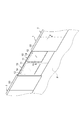
図1に示されるように、第1の実施形態に係るスクリーンドア1は、プラットホームPの線路側の縁に沿って設置されている。スクリーンドア1は、プラットホームPからの乗客の転落、又は走行中の鉄道車両との乗客の接触等を防止するための可動柵である。スクリーンドア1は、例えば、プラットホームPの線路側の縁に沿って複数配置されている。
[First Embodiment]
As shown in FIG. 1, the screen door 1 according to the first embodiment is installed along the edge of the platform P on the track side. The screen door 1 is a movable fence for preventing a passenger from falling from the platform P or a passenger's contact with a running railway vehicle. For example, a plurality of screen doors 1 are arranged along the edge of the platform P on the track side.
スクリーンドア1は、ドアパネル10と、ドアパネル10を収納可能な戸袋20と、を備えている。ドアパネル10は、プラットホームPにおいて、プラットホームPに停車する鉄道車両の乗降口に対応する位置に配置されている。ドアパネル10は、駆動機構(不図示)により、戸袋20に収納された位置と戸袋20から引き出された位置との間を往復動する。ドアパネル10及び戸袋20は、1つの乗降口に対して一対設けられている。一対のドアパネル10が互いに対向する方向に移動して戸袋20から引き出されることで、一対の戸袋20の間のスペースが閉鎖される。また、一対のドアパネル10が互いに反対方向に移動して戸袋20に収納されることで、当該スペースが開放される。
The screen door 1 includes a
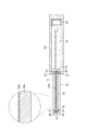
ドアパネル10は、窓部12を有する枠体11と、窓部12に組み込まれた透明なガラス部材(窓体)14と、を有している。枠体11は、例えば、金属により長方形板状に形成されており、中央よりも鉛直上側に断面長方形状の窓部12が設けられている。図2に示されるように、枠体11において、窓部12を画成する4つの内側面のそれぞれには、ガラス部材14の周縁を受け入れる断面矩形状の溝部13が設けられている。溝部13は、窓部12の内側に開口している。
The
ガラス部材14は、2枚の化学強化ガラス15が有機樹脂フィルム層(中間膜)16を介して貼り合わされてなる合わせガラスである。この例では、2枚の化学強化ガラス15は、互いに同一のものであり、互いの縁が一致するように貼り合わされている。有機樹脂フィルム層16は、化学強化ガラス15の全面にわたって貼り付けられている。なお、有機樹脂フィルム層16は、化学強化ガラス15と略同一の平面形状を有する1枚のフィルムであってもよく、複数枚に分割されていてもよい。
The
ガラス部材14は、その周縁が溝部13内に配置されるように、窓部12に組み込まれている。ガラス部材14は、ガラス部材14の表裏両面と枠体11との間にシール部材31及びバックアップ材32が配置されることによって枠体11に固定されている。シール部材31は、例えば窓部12の互いに対向する2辺においてガラス部材14と枠体11との間を水密に閉塞している。バックアップ材32は、シール部材31の外側に配置されてシール部材31の位置決めに寄与している。
The
図1及び図2に示されるように、戸袋20は、例えば金属により長方形箱状に形成されている。戸袋20の内部には、ドアパネル10を収納するための空間が形成されている。戸袋20は、例えばプラットホームPに固定された支柱33等を介してプラットホームPに固定されている。
As shown in FIGS. 1 and 2, the
スクリーンドア1の動作は、制御手段(不図示)によって制御される。例えば、スクリーンドア1は、プラットホームPに鉄道車両が停車していない時間帯には一対のドアパネル10によって一対の戸袋20の間のスペースを閉鎖し、プラットホームPに鉄道車両が停車した際に一対のドアパネル10を戸袋20に収納することによって当該スペースを開放する。当該スペースが開放されると、乗客が当該スペースを通って鉄道車両に乗り込むことが可能となる。このとき、ドアパネル10に窓部12が設けられていることで、ドアパネル10が開いて乗降通路が開放される前から、窓部12を通じてドアパネル10よりも向こう側を視認することが可能となっている。これにより、例えばプラットホームPと鉄道車両との間に隙間が空いている場合等に、ドアパネル10が開く前から乗客があらかじめ当該隙間を視認することができ、安全性の向上が図られている。
The operation of the screen door 1 is controlled by control means (not shown). For example, the screen door 1 closes the space between the pair of door pockets 20 by the pair of
以下、ガラス部材14の構成について更に説明する。まず、化学強化ガラス15について説明する。化学強化ガラス15では、イオン交換法等により、ガラス表面の小さなイオン半径のアルカリ金属原子が、大きなイオン半径のアルカリ金属原子に置き換えられる(例えば、ガラス表面のリチウム原子及び/又はナトリウム原子が、カリウム原子に置き換えられる。)ことで、ガラス表面層に大きな圧縮応力(表面圧縮応力)が付与されている。化学強化ガラス15の強度は、フロートガラス等の非強化ガラス板、又は風冷法により強化された風冷強化ガラスと比較して高められている。このため、化学強化ガラス15は、割れ難い。また、化学強化ガラス15では、フロートガラス及び風冷強化ガラスと比較して、透視映像のゆがみが低減されている。また、化学強化ガラス15では、風冷強化ガラスを用いた場合と比較して、自然破損の発生が抑制されている。
Hereinafter, the configuration of the
また、本発明者らは、化学強化ガラス15によれば、破壊時に飛散するガラス片を小さくすることができることを見出した。この理由は次のように推察される。ガラスが破壊する際には、ガラスに加えられた破壊のエネルギーが表面形成(破断面形成)のエネルギーに変換され、ガラス表面に多くの破断面が形成される。化学強化ガラス15では、強度が高められていることから、破壊時に加えられる破壊のエネルギーが大きく、それに応じて表面形成のエネルギーも大きくなっている。その結果、破壊又は破損時に多くの破断面がガラス表面に形成されることとなり、飛散するガラス片が小さくなっている。また、化学強化ガラス15の表面圧縮応力が大きくなると、破壊時に加えられる破壊のエネルギーが更に大きくなることから、それに応じて表面形成のエネルギーも更に大きくなり、その分、表面積を大きくするために、破壊又は破損時に飛散するガラス破片が更に小さくなる。
In addition, the present inventors have found that according to the chemically strengthened
化学強化ガラス15の高さは、500mm以上1800mm以下であり、化学強化ガラス15の幅は、500mm以上1500mm以下である。この例では、化学強化ガラス15の高さ及び幅の両方は、約1000mmである。なお、化学強化ガラス15の寸法は特に限定されず、スクリーンドア1の窓体に用いられる程度の大きさであればよい。
The height of the chemically strengthened
2枚の化学強化ガラス15の総厚は、1.8mm以上7.0mm以下である。化学強化ガラス15の総厚は、2.0mm以上5.0mm以下が好ましく、3.5mm以上5.0mm以下が特に好ましい。ガラス部材14では、化学強化ガラス15の総厚が7.0mm以下であるため、軽量化を図ることができ、スクリーンドア1の窓体に好適に用いられるガラス部材14を得ることができる。また、化学強化ガラス15の総厚が1.8mm以上であるため、撓み難く、透視映像にゆがみが生じ難くなっている。
The total thickness of the two chemically strengthened
1枚の化学強化ガラス15の厚さは、0.9mm以上3.5mm以下である。1枚の化学強化ガラス15の厚さは、1.0mm以上2.5mm以下が好ましく、1.8mm以上2.5mm以下が特に好ましい。ガラス部材14では、1枚の化学強化ガラス15の厚さが1.0mm以上2.5mm以下であるので、軽量で衝撃強度が高く、透視映像にゆがみが生じ難いガラス部材を得ることができる。なお、2枚の化学強化ガラス15の厚さは、互いに異なっていてもよい。その場合、2枚の化学強化ガラス15それぞれの厚さが上記範囲内であればよい。
The thickness of one chemically strengthened
化学強化ガラス15の表面圧縮応力は、400MPa以上800MPa以下である。化学強化ガラス15の表面圧縮応力は、500MPa以上が好ましく、650MPa以上が特に好ましい。化学強化ガラス15の表面圧縮応力が400MPa未満であると、強度的に劣るため、スクリーンドア1の窓体に要求される重量あたりの強度(耐衝撃性)を満たすことができない。さらには、破壊時に飛散するガラス片が大きくなり易い。対して、ガラス部材14では、化学強化ガラス15の表面圧縮応力が400MPa以上であるので、スクリーンドア1の窓体に要求される重量あたりの強度を満たすことができる。また、破壊時に飛散するガラス片を小さくすることができる。一方、表面圧縮応力が大きくなるに従って化学強化ガラス15の重量あたりの強度が大きくなるが、化学強化ガラス15の表面圧縮応力が800MPaを超えると、表面の圧縮応力層と内部の引張応力層とのバランスが低下し、わずかな歪で破壊し易くなることがある。対して、ガラス部材14では、化学強化ガラス15の表面圧縮応力が800MPa以下であるため、そのような破壊の発生が抑制されている。なお、複数枚の化学強化ガラス15によりガラス部材14が構成される場合には、すべての化学強化ガラスの表面圧縮応力が上記範囲内である必要がある。また、本明細書において、表面圧縮応力は、表面における圧縮応力を表面応力測定器にて測定した値である。
The surface compressive stress of the chemically strengthened
化学強化ガラス15は、例えば次のようにして製造される。すなわち、汎用的なソーダライムシリケートガラス等のフロートガラス板を、熔融したカリウム塩等のアルカリ金属塩に浸漬する。それによって、ガラス組成中のリチウムイオン又はナトリウムイオンが、イオン半径の大きなカリウムイオンに置換される。これにより、カリウムイオンによって増加する体積分だけ圧縮応力が生じ、表面圧縮応力が向上する。カリウム塩としては、例えば硝酸カリウム、硫酸カリウム、重硫酸カリウム、炭酸カリウム、重炭酸カリウム、及び塩化カリウム等が挙げられる。
The chemically strengthened
溶融温度は、カリウム塩の種類により異なる。例えば、硝酸カリウムの場合、好ましくは350〜500℃であり、より好ましくは370〜480℃であり、特に好ましくは450〜480℃である。350℃未満であると、化学強化処理を行う時間が長くなり、生産性に劣る。一方、熔融温度を上げると、化学強化処理時間は短縮されるが、500℃を超えても、化学強化処理時間は大幅に短縮されず、使用するカリウム塩の種類によっては、有害なガスを発生し作業環境を損なう場合がある。 The melting temperature varies depending on the type of potassium salt. For example, in the case of potassium nitrate, it is preferably 350 to 500 ° C, more preferably 370 to 480 ° C, and particularly preferably 450 to 480 ° C. When the temperature is lower than 350 ° C., the time for performing the chemical strengthening treatment becomes long and the productivity is poor. On the other hand, when the melting temperature is raised, the chemical strengthening treatment time is shortened, but even if it exceeds 500 ° C, the chemical strengthening treatment time is not significantly shortened, and depending on the type of potassium salt used, harmful gas is generated. However, the work environment may be impaired.
浸漬時間は、フロートガラス板の厚み、得られる化学強化ガラス15の表面圧縮応力により異なるので特に限定はしない。例えば、厚さ3mm以上6mm以下のフロートガラス板を用いて、表面圧縮応力400MPa以上800MPa以下の化学強化ガラス15を得る場合、450〜500℃の溶融した硝酸カリウム中に、1〜5時間、好ましくは2〜4時間浸漬すればよい。
The immersion time is not particularly limited because it varies depending on the thickness of the float glass plate and the surface compressive stress of the resulting chemically strengthened
有機樹脂フィルム層16は、例えば熱可塑性樹脂、熱硬化性樹脂、又は紫外線硬化性樹脂等で構成されており、ビニル系ポリマー、エチレン−ビニル系モノマー共重合体、スチレン系共重合体、ポリウレタン樹脂、フッ素樹脂及びアクリル樹脂から選ばれる1種以上で構成されていることが好ましい。なかでも、経済性、及び製造工程での加工性に優れていることから、ビニル系ポリマー及び/又はエチレン−ビニル系モノマー共重合体がより好ましい。
The organic
有機樹脂フィルム層16の厚さは、0.7mm以上1.6mm以下である。有機樹脂フィルム層16の厚さは、0.7mm以上1.0mm以下が好ましい。ガラス部材14では、有機樹脂フィルム層16の厚さが0.7mm以上1.6mm以下であるため、透視映像にゆがみが生じ難くすると共に、破損した場合のガラス片の飛散を抑制することができる。
The thickness of the organic
有機樹脂フィルム層16の破断強度は、30MPa以上であり、有機樹脂フィルム層16の破断伸度は、250%以上である。有機樹脂フィルム層16の破断強度は、30MPa以上200MPa以下が好ましい。有機樹脂フィルム層16の破断伸度は、300%以上500%以下が好ましく、400%以上500%以下が特に好ましい。このような有機樹脂フィルム層16としては、ポリビニルブチラール、エチレン酢酸ビニル共重合体、及びアイオノマー樹脂から選択される1種の樹脂により構成されたものが挙げられる。有機樹脂フィルム層16の破断強度及び破断伸度がこれらの範囲内であれば、有機樹脂フィルム層16の強度を確保できることから、ガラス部材14が破損した場合であっても有機樹脂フィルム層16が破断し難く、ガラス片の飛散を抑制することができる。なお、本明細書において、破断強度及び破断伸度は、JIS K 7161に準じて測定した値である。
The breaking strength of the organic
ガラス部材14は、例えば以下のようにして製造される。すなわち、1枚目の化学強化ガラス15の上に、シート状の有機樹脂フィルム材料を置き、その上に2枚目の化学強化ガラス15を重ね合せ、ロールプレス法等により加熱下で予備圧着させた後、1〜12気圧、120〜160℃のオートクレーブ中で本圧着を行い、2枚の化学強化ガラス15を有機樹脂フィルム層16によって接着させる。あるいは、2枚の化学強化ガラス15の間に間隙を設け、その間隙に有機樹脂フィルム材料として液状の紫外線硬化性組成物を注入した後、紫外線を照射して有機樹脂フィルム材料を硬化させて有機樹脂フィルム層16を形成することで、2枚の化学強化ガラス15を接着させてもよい。
The
[第2の実施形態]
図3を参照しつつ、第2の実施形態に係るスクリーンドアを説明する。第2の実施形態に係るスクリーンドアは、窓部12にガラス部材14Aが組み込まれている点で、第1の実施形態に係るスクリーンドア1と相違している。
[Second Embodiment]
A screen door according to a second embodiment will be described with reference to FIG. The screen door according to the second embodiment is different from the screen door 1 according to the first embodiment in that a
ガラス部材14Aでは、1枚の化学強化ガラス15Aに有機樹脂フィルム層16Aが貼り合わされてなる単板ガラスである。ガラス部材14Aは、有機樹脂フィルム層16Aが線路側に位置するように窓部12に組み込まれている。ガラス部材14Aの化学強化ガラス15Aの厚さは、1.8mm以上7.0mm以下である。化学強化ガラス15Aの厚さは、3.0mm以上5.0mm以下が好ましく、3.5mm以上5.0mm以下がより好ましい。化学強化ガラス15Aの厚さが3.0mm以上5.0mm以下であれば、透視映像にゆがみが生じ難くすると共に、破損した場合のガラス片の飛散を抑制することができる。化学強化ガラス15Aの表面圧縮応力は、第1の実施形態と同様である。
The
有機樹脂フィルム層16Aは、化学強化ガラス15Aの片面に接着剤等によって貼り付けられている。この接着剤は、特に限定されず、種々のものを用いることができる。有機樹脂フィルム層16Aの厚さは、50μm以上130μm以下である。有機樹脂フィルム層16Aの厚さは、50μm以上100μm以下が好ましい。ガラス部材14Aでは、有機樹脂フィルム層16Aの厚さが50μm以上130μm以下であるため、透視映像にゆがみが生じ難くすると共に、破損した場合のガラス片の飛散を抑制することができる。
The organic
有機樹脂フィルム層16Aの破断強度は、100MPa以上であり、有機樹脂フィルム層16Aの破断伸度は、80%以上である。有機樹脂フィルム層16Aの破断強度は、100MPa以上250MPa以下が好ましい。有機樹脂フィルム層16Aの破断伸度は、100%以上400%以下が好ましい。このような有機樹脂フィルム層16Aとしては、ポリエチレンテレフタレートフィルム、ポリカーボネートフィルム、ポリアミドフィルムが挙げられ、より好ましくはポリエチレンテレフタレートフィルムが挙げられる。有機樹脂フィルム層16Aの破断強度及び破断伸度がこれらの範囲内であれば、有機樹脂フィルム層16Aの強度を確保できることから、ガラス部材14Aが破損した場合であっても有機樹脂フィルム層16Aが破断し難く、ガラス片の飛散を抑制することができる。
The breaking strength of the organic
また、図4に示される変形例に係るスクリーンドアのように構成してもよい。変形例に係るスクリーンドアは、ガラス部材14Aの窓部12に対する取付態様において、第2の実施形態に係るスクリーンドアと相違している。変形例に係るスクリーンドアでは、溝部13Bは、枠体11の内側面において、線路側の反対端に設けられている。そして、ガラス部材14Aにおける有機樹脂フィルム層16Aが貼り付けられた側の面と枠体11との間にシール部材34が配置されると共に、ガラス部材14Aにおける表裏両面に連続する側面と枠体11との間にシール部材35が配置されることによって、ガラス部材14Aが枠体11に固定されている。シール部材34及びシール部材35は、例えば窓部12の互いに対向する2辺においてガラス部材14Aと枠体11との間を水密に閉塞している。
Moreover, you may comprise like the screen door which concerns on the modification shown by FIG. The screen door which concerns on a modification differs from the screen door which concerns on 2nd Embodiment in the attachment aspect with respect to the
以下では実施例及び比較例を参照しつつ本発明を更に詳細に説明するが、本発明はこれらの例によって何ら限定されるものではない。 Hereinafter, the present invention will be described in more detail with reference to examples and comparative examples, but the present invention is not limited to these examples.
[実施例1]
幅800mm、高さ1000mmで、厚さ3.0mmのソーダライムシリケート系フロートガラス板を、約450℃に加熱して溶融した硝酸カリウムに4.0時間浸漬して、表面圧縮応力680MPa、厚さ3.0mm、単位面積あたりの重量7.5kg/m2の化学強化ガラスAを得た。化学強化ガラスAの上に、ポリマー中間膜(有機樹脂フィルム層)として厚み0.762mmのポリビニルブチラールフィルムを載せ、その上に更に化学強化ガラスAを載せ、予備圧着、本圧着をして、ガラス部分の総厚が6.0mmの実施例1のガラス部材(合わせガラス)を製造した。このガラス部材の単位面積あたりの重量は15.82kg/m2であった。
[Example 1]
A soda lime silicate float glass plate having a width of 800 mm, a height of 1000 mm, and a thickness of 3.0 mm is immersed in molten potassium nitrate by heating to about 450 ° C. for 4.0 hours to obtain a surface compressive stress of 680 MPa and a thickness of 3 A chemically strengthened glass A having a thickness of 0.0 mm and a weight per unit area of 7.5 kg / m 2 was obtained. On the chemically strengthened glass A, a polyvinyl butyral film having a thickness of 0.762 mm is placed as a polymer intermediate film (organic resin film layer). Further, the chemically strengthened glass A is placed on the glass, and pre-bonding and main-bonding are performed. A glass member (laminated glass) of Example 1 having a total thickness of 6.0 mm was manufactured. The glass member had a weight per unit area of 15.82 kg / m 2 .
[実施例2]
幅800mm、高さ1000mmで、厚さ2.0mmのソーダライムシリケート系フロートガラス板を、約450℃に加熱して溶融した硝酸カリウムに4.0時間浸漬して、表面圧縮応力680MPa、厚さ1.8mm、単位面積あたりの重量5.0kg/m2の化学強化ガラスBを得た。化学強化ガラスBの上に、ポリマー中間膜(有機樹脂フィルム層)として厚み0.762mmのエチレン−ビニル系モノマー共重合体フィルムを載せ、その上に更に化学強化ガラスBを載せ、予備圧着、本圧着をして、ガラス部分の総厚が3.6mmの実施例2のガラス部材(合わせガラス)を製造した。このガラス部材の単位面積あたりの重量は10.82kg/m2であった。
[Example 2]
A soda lime silicate float glass plate having a width of 800 mm, a height of 1000 mm, and a thickness of 2.0 mm is immersed in molten potassium nitrate heated to about 450 ° C. for 4.0 hours, and has a surface compressive stress of 680 MPa and a thickness of 1 A chemically strengthened glass B having a weight of .8 mm and a weight per unit area of 5.0 kg / m 2 was obtained. On the chemically tempered glass B, an ethylene-vinyl monomer copolymer film having a thickness of 0.762 mm is placed as a polymer intermediate film (organic resin film layer). The glass member (laminated glass) of Example 2 having a total glass portion thickness of 3.6 mm was manufactured by pressure bonding. The glass member had a weight per unit area of 10.82 kg / m 2 .
[実施例3]
幅800mm、高さ1000mmで、厚さ3.0mmのソーダライムシリケート系フロートガラス板を、約450℃に加熱して溶融した硝酸カリウムに3.5時間浸漬して、表面圧縮応力530MPa、厚さ3.0mm、単位面積あたりの重量7.5kg/m2の化学強化ガラスCを得た。化学強化ガラスCの上に、ポリマー中間膜(有機樹脂フィルム層)として厚み0.762mmのポリビニルブチラールフィルムを載せ、その上に更に化学強化ガラスCを載せ、予備圧着、本圧着をして、ガラス部分の総厚が6.0mmの実施例3のガラス部材(合わせガラス)を製造した。このガラス部材の単位面積あたりの重量は15.82kg/m2であった。
[Example 3]
A soda lime silicate float glass plate having a width of 800 mm, a height of 1000 mm, and a thickness of 3.0 mm is immersed in molten potassium nitrate heated to about 450 ° C. for 3.5 hours to obtain a surface compressive stress of 530 MPa and a thickness of 3 A chemically strengthened glass C having a thickness of 0.0 mm and a weight per unit area of 7.5 kg / m 2 was obtained. On the chemically tempered glass C, a polyvinyl butyral film having a thickness of 0.762 mm is placed as a polymer intermediate film (organic resin film layer). Further, the chemically tempered glass C is further placed thereon, pre-crimped and finally crimped, and glass A glass member (laminated glass) of Example 3 having a total thickness of 6.0 mm was produced. The glass member had a weight per unit area of 15.82 kg / m 2 .
[実施例4]
幅800mm、高さ1000mmで、厚さ1.1mmのソーダライムシリケート系フロートガラス板を、約450℃に加熱して溶融した硝酸カリウムに4.0時間浸漬して、表面圧縮応力680MPa、厚さ1.1mm、単位面積あたりの重量2.75kg/m2の化学強化ガラスDを得た。化学強化ガラスDの上に、ポリマー中間膜(有機樹脂フィルム層)として厚み0.762mmのポリビニルブチラールフィルムを載せ、その上に更に化学強化ガラスBを載せ、予備圧着、本圧着をして、ガラス部分の総厚が2.2mmの実施例4のガラス部材(合わせガラス)を製造した。このガラス部材の単位面積あたりの重量は6.32kg/m2であった。
[Example 4]
A soda lime silicate float glass plate having a width of 800 mm, a height of 1000 mm, and a thickness of 1.1 mm is immersed in molten potassium nitrate by heating to about 450 ° C. for 4.0 hours to obtain a surface compressive stress of 680 MPa and a thickness of 1 A chemically strengthened glass D having a thickness of 0.1 mm and a weight per unit area of 2.75 kg / m 2 was obtained. On the chemically tempered glass D, a polyvinyl butyral film having a thickness of 0.762 mm is placed as a polymer intermediate film (organic resin film layer), and further a chemically tempered glass B is placed thereon, followed by pre-compression bonding and main-compression bonding. A glass member (laminated glass) of Example 4 having a total thickness of 2.2 mm was produced. The glass member had a weight per unit area of 6.32 kg / m 2 .
[実施例5]
化学強化ガラスAに、厚み60μmのポリエチレンテレフタレートフィルムを圧着させて、ガラス部分の総厚が3.0mmの実施例5のガラス部材(単板ガラス)を製造した。このガラス部材の単位面積あたりの質量は、8.24kg/m2であった。
[Example 5]
A polyethylene terephthalate film having a thickness of 60 μm was pressure-bonded to the chemically strengthened glass A to produce a glass member (single plate glass) of Example 5 having a total glass portion thickness of 3.0 mm. The mass per unit area of this glass member was 8.24 kg / m 2 .
[比較例1]
幅800mm、高さ1000mmで、厚さ3.0mmのソーダライムシリケート系フロートガラス板を、約450℃に加熱して溶融した硝酸カリウムに2.0時間浸漬して、表面圧縮応力320MPa、厚さ3.0mm、単位面積あたりの重量7.5kg/m2の化学強化ガラスEを得た。化学強化ガラスEの上に、ポリマー中間膜(有機樹脂フィルム層)として厚み0.762mmのポリビニルブチラールフィルムを載せ、その上に更に化学強化ガラスAを載せ、予備圧着、本圧着をして、ガラス部分の総厚が6.0mmの比較例1のガラス部材(合わせガラス)を製造した。このガラス部材の単位面積あたりの重量は15.82kg/m2であった。
[Comparative Example 1]
A soda lime silicate float glass plate having a width of 800 mm, a height of 1000 mm, and a thickness of 3.0 mm was immersed in molten potassium nitrate for about 2.0 hours by heating to about 450 ° C., and a surface compressive stress of 320 MPa and a thickness of 3 A chemically strengthened glass E having a thickness of 0.0 mm and a weight per unit area of 7.5 kg / m 2 was obtained. On the chemically tempered glass E, a polyvinyl butyral film having a thickness of 0.762 mm is placed as a polymer intermediate film (organic resin film layer), and a chemically tempered glass A is further placed thereon, and pre-crimping and main-crimping are performed. A glass member (laminated glass) of Comparative Example 1 having a total thickness of 6.0 mm was produced. The glass member had a weight per unit area of 15.82 kg / m 2 .
[比較例2]
化学強化ガラスAの上に、ポリマー中間膜(有機樹脂フィルム層)として厚み0.762mmのポリビニルブチラールフィルムを載せ、その上に更に化学強化を施していない厚さ3.0mmのソーダライムシリケート系フロートガラス板を載せ、予備圧着、本圧着をして、ガラス部分の総厚が6.0mmの比較例2のガラス部材(合わせガラス)を製造した。このガラス部材の単位面積あたりの重量は15.82kg/m2であった。
[Comparative Example 2]
A 0.762 mm thick polyvinyl butyral film is placed on the chemically tempered glass A as a polymer interlayer (organic resin film layer), and a 3.0 mm thick soda lime silicate float that is not further chemically reinforced. A glass plate was placed, pre-bonded, and main-bonded to produce a glass member (laminated glass) of Comparative Example 2 having a total glass portion thickness of 6.0 mm. The glass member had a weight per unit area of 15.82 kg / m 2 .
[比較例3]
幅800mm、高さ1000mmで、厚さ1.1mmのソーダライムシリケート系フロートガラス板を、約450℃に加熱して溶融した硝酸カリウムに2.5時間浸漬して、表面圧縮応力380MPa、厚さ1.1mm、単位面積あたりの重量2.75kg/m2の化学強化ガラスFを得た。化学強化ガラスFの上に、ポリマー中間膜(有機樹脂フィルム層)として厚み0.762mmのポリビニルブチラールフィルムを載せ、その上に更に化学強化ガラスDを載せ、予備圧着、本圧着をして、ガラス部分の総厚が2.2mmの比較例3のガラス部材(合わせガラス)を製造した。このガラス部材の単位面積あたりの重量は6.32kg/m2であった。
[Comparative Example 3]
A soda lime silicate float glass plate having a width of 800 mm, a height of 1000 mm, and a thickness of 1.1 mm was immersed in molten potassium nitrate by heating to about 450 ° C. for 2.5 hours to obtain a surface compressive stress of 380 MPa and a thickness of 1 A chemically strengthened glass F having a thickness of 0.1 mm and a weight per unit area of 2.75 kg / m 2 was obtained. On the chemically tempered glass F, a polyvinyl butyral film having a thickness of 0.762 mm is placed as a polymer intermediate film (organic resin film layer), and a chemically tempered glass D is further placed on the polyvinyl butyral film. A glass member (laminated glass) of Comparative Example 3 having a total thickness of 2.2 mm was produced. The glass member had a weight per unit area of 6.32 kg / m 2 .
[比較例4]
厚さ6mmで、単位面積あたりの重量が15.0kg/m2である市販の風冷強化ガラスに、実施例5と同様の厚さ60μmのポリエチレンテレフタレートフィルムを圧着させて、ガラス部分の総厚が6.0mmの比較例4のガラス部材(単板ガラス)を製造した。このガラス部材の単位面積あたりの重量は15.74kg/m2であった。
[Comparative Example 4]
A polyethylene terephthalate film having a thickness of 60 μm similar to that in Example 5 was pressure-bonded to a commercially available air-cooled tempered glass having a thickness of 6 mm and a weight per unit area of 15.0 kg / m 2 to obtain a total thickness of the glass portion. Produced a glass member (single plate glass) of Comparative Example 4 having a thickness of 6.0 mm. The glass member had a weight per unit area of 15.74 kg / m 2 .
[落球試験]
JIS R 3205に規定されている「7.6落球試験」に準拠し、落球試験を行った。実施例1〜5、比較例1〜4のガラス部材から、610mm角を切り出し、試験片とした。落球試験の手順は以下の通りとした。水平に置かれた試験片に対して、落下高さが所定値となる高さから質量1040gの鋼球を1回落下させた。試験片が破壊した場合、当該落下高さを評価結果とした。試験片が破壊しなかった場合、試験片が破壊するまで所定の順序に従って落下高さを順次上げて鋼球を落下させ、試験片が破壊した落下高さを評価結果とした。落下高さを上げる順序は、300mm,600mm,900mm,1200mm,1500mm,1900mm,2400mm,3000mm,3800mm,4800mmとした。なお、比較例1では、化学強化ガラスE側を鋼球が接触する面として評価を行った。比較例2では、ソーダライムシリケート系フロートガラス板側を鋼球が接触する面として評価を行った。比較例3では、化学強化ガラスF側を鋼球が接触する面として評価を行った。
[Falling ball test]
A falling ball test was conducted in accordance with “7.6 falling ball test” defined in JIS R 3205. A 610 mm square was cut out from the glass members of Examples 1 to 5 and Comparative Examples 1 to 4, and used as test pieces. The procedure for the falling ball test was as follows. A steel ball having a mass of 1040 g was dropped once from a height at which the drop height reached a predetermined value with respect to the test piece placed horizontally. When the test piece was broken, the drop height was used as an evaluation result. When the test piece did not break, the drop height was sequentially increased according to a predetermined order until the test piece broke, the steel balls were dropped, and the drop height at which the test piece broke was used as the evaluation result. The order of increasing the drop height was 300 mm, 600 mm, 900 mm, 1200 mm, 1500 mm, 1900 mm, 2400 mm, 3000 mm, 3800 mm, 4800 mm. In Comparative Example 1, the evaluation was performed with the chemically strengthened glass E side as the surface in contact with the steel ball. In Comparative Example 2, the soda lime silicate float glass plate side was evaluated as the surface in contact with the steel balls. In Comparative Example 3, the evaluation was performed with the chemically tempered glass F side as the surface in contact with the steel ball.
[ショットバッグ試験]
JIS R 3205に規定されている「7.7ショットバッグ試験」に準拠し、ショットバッグ試験を行った。実施例1〜5、比較例1〜4のガラス部材から、幅765mm高さ920mmを切り出し、試験片とした。ショットバッグ試験の手順は以下の通りとした。地面に対して垂直に設置した試験片に対して、質量45kgの加撃体である振り子を、振り子の最下点が試験片の中央になるように調整した。最下点からの高さが所定値となる位置に加撃体を保持した後、加撃体を振り子式に自由落下させ、試験片の中心点付近を1回加撃した。試験片が破壊した場合、当該落下高さを評価結果とした。試験片が破壊しなかった場合、試験片が破壊するまで所定の順序に従って最下点からの高さを順次上げて加撃体を振り子式に自由落下させ、試験片が破壊した最下点からの高さを評価結果とした。最下点から高さを上げる順序は、300mm,380mm,480mm,610mm,770mm,960mm,1200mm,1500mm,1900mm,2300mmとした。なお、比較例1では、化学強化ガラスE側を加撃体が接触する面として評価を行った。比較例2では、ソーダライムシリケート系フロートガラス板側を加撃体が接触する面として評価を行った。比較例3では、化学強化ガラスF側を鋼球が接触する面として評価を行った。
[Shot bag test]
A shot bag test was conducted in accordance with “7.7 shot bag test” defined in JIS R 3205. From the glass members of Examples 1 to 5 and Comparative Examples 1 to 4, a width of 765 mm and a height of 920 mm were cut out and used as test pieces. The procedure for the shot bag test was as follows. A pendulum, which is an impactor with a mass of 45 kg, was adjusted so that the lowest point of the pendulum was at the center of the test piece with respect to the test piece installed perpendicular to the ground. After holding the impactor at a position where the height from the lowest point becomes a predetermined value, the impactor was dropped freely in a pendulum manner, and the vicinity of the center point of the test piece was impacted once. When the test piece was broken, the drop height was used as an evaluation result. If the test piece did not break, raise the height from the lowest point in order according to a predetermined sequence until the test piece broke, and let the impactor fall free in a pendulum manner, from the lowest point where the test piece broke Was used as the evaluation result. The order of increasing the height from the lowest point was 300 mm, 380 mm, 480 mm, 610 mm, 770 mm, 960 mm, 1200 mm, 1500 mm, 1900 mm, 2300 mm. In Comparative Example 1, the evaluation was performed with the chemically tempered glass E side as the surface with which the impactor contacts. In Comparative Example 2, the soda lime silicate float glass plate side was evaluated as the surface with which the impactor contacted. In Comparative Example 3, the evaluation was performed with the chemically tempered glass F side as the surface in contact with the steel ball.
図5には、実施例1〜5及び比較例1〜4のガラス部材の単位面積当たりの重量、落球試験、及びショットバッグ試験の結果が示されている。実施例1〜4の結果より、ガラス部材を合わせガラスとした場合、ガラス部材の厚さが増加して単位面積当たりの重量が増加するに伴い、落球試験及びショットバッグ試験の結果が向上したことが分かる。単位面積当たりの重量が等しい実施例1,3と比較例1,2とを比較すると、落球試験及びショットバッグ試験の両方において実施例1,3は比較例1,2よりも大きい値を示しており、本発明のガラス部材は衝撃強度において優れていることが分かる。 FIG. 5 shows the results of the weight per unit area, the falling ball test, and the shot bag test of the glass members of Examples 1 to 5 and Comparative Examples 1 to 4. From the results of Examples 1 to 4, when the glass member was laminated glass, the results of the falling ball test and the shot bag test were improved as the thickness of the glass member increased and the weight per unit area increased. I understand. When Examples 1 and 3 having the same weight per unit area and Comparative Examples 1 and 2 were compared, Examples 1 and 3 showed larger values than Comparative Examples 1 and 2 in both the falling ball test and the shot bag test. It can be seen that the glass member of the present invention is excellent in impact strength.
一方、落球試験及びショットバッグ試験の値が等しい実施例2と比較例2とを比較すると、実施例2の単位面積あたりの重量が比較例2よりも小さくなっており、本発明のガラス部材では軽量化が図られることが分かる。同様の結果は、単板ガラス部材の実施例5と比較例4の比較からも伺える。また、実施例4と比較例3との比較から、2枚のうちの1枚の化学強化ガラスの表面圧縮応力が400MPa未満である場合、スクリーンドア1の窓体に要求される重量当たりの強度が得られないことが確認された。 On the other hand, when Example 2 and Comparative Example 2 having the same values of the falling ball test and shot bag test are compared, the weight per unit area of Example 2 is smaller than that of Comparative Example 2, and in the glass member of the present invention, It can be seen that the weight can be reduced. Similar results can be seen from a comparison between Example 5 and Comparative Example 4 of the single glass member. Further, from the comparison between Example 4 and Comparative Example 3, when the surface compressive stress of one of the two chemically strengthened glasses is less than 400 MPa, the strength per weight required for the window body of the screen door 1. It was confirmed that was not obtained.
以上、本発明の好適な実施形態について説明したが、本発明は、上記実施形態に限られるものではなく、各請求項に記載した要旨を変更しない範囲で変形し、又は他のものに適用してもよい。 The preferred embodiments of the present invention have been described above. However, the present invention is not limited to the above-described embodiments. The present invention can be modified without departing from the scope described in the claims or applied to other embodiments. May be.
例えば、上記第1の実施形態ではガラス部材14が2枚の化学強化ガラス15を備え、上記第2の実施形態ではガラス部材14Aが1枚の化学強化ガラス15Aを備えていたが、ガラス部材は3枚以上の化学強化ガラスを備えていてもよい。
For example, in the first embodiment, the
1…スクリーンドア、14,14A…ガラス部材、15,15A…化学強化ガラス、16…有機樹脂フィルム層、P…プラットホーム。 DESCRIPTION OF SYMBOLS 1 ... Screen door, 14, 14A ... Glass member, 15, 15A ... Chemically tempered glass, 16 ... Organic resin film layer, P ... Platform.
Claims (8)
1又は複数の化学強化ガラスと、有機樹脂フィルム層と、を備え、
前記化学強化ガラスの総厚は、1.8mm以上7.0mm以下であり、
前記1又は複数の化学強化ガラスの表面圧縮応力は、400MPa以上800MPa以下である、ガラス部材。 A glass member used for a window body of a screen door installed on a platform,
One or a plurality of chemically strengthened glass and an organic resin film layer,
The total thickness of the chemically strengthened glass is 1.8 mm or more and 7.0 mm or less,
The glass member whose surface compressive stress of said 1 or a plurality of chemically strengthened glass is 400MPa or more and 800MPa or less.
2枚の前記化学強化ガラスそれぞれの厚さは、1.0mm以上3.5mm以下である、請求項1又は2記載のガラス部材。 Two sheets of the chemically strengthened glass are bonded together via the organic resin film layer,
The glass member according to claim 1 or 2, wherein each of the two chemically strengthened glasses has a thickness of 1.0 mm or more and 3.5 mm or less.
前記化学強化ガラスの厚さは、3.0mm以上5.0mm以下である、請求項1又は2記載のガラス部材。 The organic resin film layer is bonded to one piece of the chemically strengthened glass,
The glass member according to claim 1 or 2, wherein a thickness of the chemically strengthened glass is 3.0 mm or greater and 5.0 mm or less.
Priority Applications (1)
| Application Number | Priority Date | Filing Date | Title |
|---|---|---|---|
| JP2015141066A JP2017019706A (en) | 2015-07-15 | 2015-07-15 | Glass member |
Applications Claiming Priority (1)
| Application Number | Priority Date | Filing Date | Title |
|---|---|---|---|
| JP2015141066A JP2017019706A (en) | 2015-07-15 | 2015-07-15 | Glass member |
Publications (1)
| Publication Number | Publication Date |
|---|---|
| JP2017019706A true JP2017019706A (en) | 2017-01-26 |
Family
ID=57887595
Family Applications (1)
| Application Number | Title | Priority Date | Filing Date |
|---|---|---|---|
| JP2015141066A Pending JP2017019706A (en) | 2015-07-15 | 2015-07-15 | Glass member |
Country Status (1)
| Country | Link |
|---|---|
| JP (1) | JP2017019706A (en) |
Citations (8)
| Publication number | Priority date | Publication date | Assignee | Title |
|---|---|---|---|---|
| JP2013023912A (en) * | 2011-07-21 | 2013-02-04 | Nippon Steel & Sumikin Metal Products Co Ltd | Laminated glass and translucent soundproof panel |
| JP2013173488A (en) * | 2012-02-27 | 2013-09-05 | Mitsubishi Heavy Industries Transportation Equipment Engineering & Service Co Ltd | Platform door device |
| JP2014097736A (en) * | 2012-11-15 | 2014-05-29 | Toho Tenax Co Ltd | Platform door device |
| WO2014176059A1 (en) * | 2013-04-22 | 2014-10-30 | Corning Incorporated | Laminated glass structures having high glass to polymer interlayer adhesion |
| WO2015010922A1 (en) * | 2013-07-24 | 2015-01-29 | Schott Ag | Composite element and use thereof |
| US20150064374A1 (en) * | 2013-08-30 | 2015-03-05 | Corning Incorporated | Light-weight, high stiffness glass laminate structure |
| JP2015098426A (en) * | 2013-11-20 | 2015-05-28 | 藤原工業株式会社 | Chemically strengthened glass with printed layer and use thereof |
| JP2015143182A (en) * | 2013-12-25 | 2015-08-06 | 旭硝子株式会社 | Glass substrate for movable home fence and glass laminate |
-
2015
- 2015-07-15 JP JP2015141066A patent/JP2017019706A/en active Pending
Patent Citations (8)
| Publication number | Priority date | Publication date | Assignee | Title |
|---|---|---|---|---|
| JP2013023912A (en) * | 2011-07-21 | 2013-02-04 | Nippon Steel & Sumikin Metal Products Co Ltd | Laminated glass and translucent soundproof panel |
| JP2013173488A (en) * | 2012-02-27 | 2013-09-05 | Mitsubishi Heavy Industries Transportation Equipment Engineering & Service Co Ltd | Platform door device |
| JP2014097736A (en) * | 2012-11-15 | 2014-05-29 | Toho Tenax Co Ltd | Platform door device |
| WO2014176059A1 (en) * | 2013-04-22 | 2014-10-30 | Corning Incorporated | Laminated glass structures having high glass to polymer interlayer adhesion |
| WO2015010922A1 (en) * | 2013-07-24 | 2015-01-29 | Schott Ag | Composite element and use thereof |
| US20150064374A1 (en) * | 2013-08-30 | 2015-03-05 | Corning Incorporated | Light-weight, high stiffness glass laminate structure |
| JP2015098426A (en) * | 2013-11-20 | 2015-05-28 | 藤原工業株式会社 | Chemically strengthened glass with printed layer and use thereof |
| JP2015143182A (en) * | 2013-12-25 | 2015-08-06 | 旭硝子株式会社 | Glass substrate for movable home fence and glass laminate |
Similar Documents
| Publication | Publication Date | Title |
|---|---|---|
| US11691390B2 (en) | Light-weight hybrid glass laminates | |
| EP3137428B1 (en) | Strengthened glass and compositions therefor | |
| EP3144141B2 (en) | Laminated glass | |
| US20200262746A1 (en) | Protective cover, its use and method of making a protective cover | |
| JP6080279B2 (en) | Method of producing ion exchange glass and resulting apparatus | |
| KR102043438B1 (en) | Glass laminate construction for optimized breakage performance | |
| TWI652164B (en) | Glass-layered structure of the head-up display system | |
| EP2552688B1 (en) | Transparent glass-polymer composite | |
| CN103827395B (en) | Laminated glass and light transmission baffle-board | |
| CN110139752A (en) | Composite glass | |
| EP2705951B1 (en) | Transparent laminate which inhibits puncture by projectiles | |
| WO2018084041A1 (en) | Laminated glass | |
| WO2019038720A1 (en) | Transparent multi-hit armor | |
| CN115448583A (en) | Glass assembly, preparation method thereof and vehicle | |
| JP2020172404A (en) | Laminated glass for vehicles | |
| JP2020172403A (en) | Laminated glass for vehicles | |
| JP2016075122A (en) | Sound insulation wall | |
| JP2017019706A (en) | Glass member | |
| CN204894673U (en) | Chemically tempered laminated ultra-thin glass for automobile front shield | |
| JP2018070417A (en) | Noise insulation plate | |
| CN203331501U (en) | Anti-smashing laminated glass | |
| JP2014029109A (en) | Road-side panel | |
| JP5927675B2 (en) | Roadside installation panel | |
| KR101526109B1 (en) | Chemical tempered glass containing printed layer | |
| CN204605465U (en) | The anti-windshield that splits |
Legal Events
| Date | Code | Title | Description |
|---|---|---|---|
| A621 | Written request for application examination |
Free format text: JAPANESE INTERMEDIATE CODE: A621 Effective date: 20180509 |
|
| A977 | Report on retrieval |
Free format text: JAPANESE INTERMEDIATE CODE: A971007 Effective date: 20181122 |
|
| A131 | Notification of reasons for refusal |
Free format text: JAPANESE INTERMEDIATE CODE: A131 Effective date: 20190108 |
|
| A02 | Decision of refusal |
Free format text: JAPANESE INTERMEDIATE CODE: A02 Effective date: 20190702 |