JP2017053473A - Light irradiation device, light-emitting unit, and method for manufacturing light irradiation device - Google Patents
Light irradiation device, light-emitting unit, and method for manufacturing light irradiation device Download PDFInfo
- Publication number
- JP2017053473A JP2017053473A JP2015179650A JP2015179650A JP2017053473A JP 2017053473 A JP2017053473 A JP 2017053473A JP 2015179650 A JP2015179650 A JP 2015179650A JP 2015179650 A JP2015179650 A JP 2015179650A JP 2017053473 A JP2017053473 A JP 2017053473A
- Authority
- JP
- Japan
- Prior art keywords
- coupling portion
- unit
- light
- main body
- light irradiation
- Prior art date
- Legal status (The legal status is an assumption and is not a legal conclusion. Google has not performed a legal analysis and makes no representation as to the accuracy of the status listed.)
- Pending
Links
- 238000004519 manufacturing process Methods 0.000 title claims abstract description 22
- 238000000034 method Methods 0.000 title abstract description 7
- 230000008878 coupling Effects 0.000 claims description 79
- 238000010168 coupling process Methods 0.000 claims description 79
- 238000005859 coupling reaction Methods 0.000 claims description 79
- 239000011347 resin Substances 0.000 claims description 8
- 229920005989 resin Polymers 0.000 claims description 8
- 230000005855 radiation Effects 0.000 claims description 6
- 230000001678 irradiating effect Effects 0.000 claims description 5
- 239000010865 sewage Substances 0.000 abstract 1
- 229920002430 Fibre-reinforced plastic Polymers 0.000 description 7
- 239000011151 fibre-reinforced plastic Substances 0.000 description 7
- 239000000758 substrate Substances 0.000 description 4
- 230000002093 peripheral effect Effects 0.000 description 3
- 230000001681 protective effect Effects 0.000 description 3
- RYGMFSIKBFXOCR-UHFFFAOYSA-N Copper Chemical compound [Cu] RYGMFSIKBFXOCR-UHFFFAOYSA-N 0.000 description 2
- 229910000831 Steel Inorganic materials 0.000 description 2
- 229910052802 copper Inorganic materials 0.000 description 2
- 239000010949 copper Substances 0.000 description 2
- 238000003780 insertion Methods 0.000 description 2
- 230000037431 insertion Effects 0.000 description 2
- 239000010959 steel Substances 0.000 description 2
- 230000002159 abnormal effect Effects 0.000 description 1
- 239000000919 ceramic Substances 0.000 description 1
- 238000010276 construction Methods 0.000 description 1
- 238000000605 extraction Methods 0.000 description 1
- 239000004744 fabric Substances 0.000 description 1
- 239000003365 glass fiber Substances 0.000 description 1
- 230000002452 interceptive effect Effects 0.000 description 1
- 239000000463 material Substances 0.000 description 1
- 239000002184 metal Substances 0.000 description 1
- 229910052751 metal Inorganic materials 0.000 description 1
- 239000004033 plastic Substances 0.000 description 1
- 229920003023 plastic Polymers 0.000 description 1
- 239000004417 polycarbonate Substances 0.000 description 1
- 229920000515 polycarbonate Polymers 0.000 description 1
- 125000006850 spacer group Chemical group 0.000 description 1
Images

Landscapes
- Lining Or Joining Of Plastics Or The Like (AREA)
Abstract
Description
本発明は、下水道管などの管きょを補修するFRP内面補修工法に用いられる光照射装置、発光ユニット、及び、光照射装置の製造方法に関する。 The present invention relates to a light irradiation device, a light emitting unit, and a method for manufacturing the light irradiation device used in an FRP inner surface repair method for repairing a pipe such as a sewer pipe.
従来、ガラス繊維織物に光硬化性樹脂を含浸した筒状の未硬化ライナーを管きょの内周面に密着させ、内側から光を照射して硬化させることで、管きょの内周面を繊維強化プラスチック(FRP)のライナーで覆うFRP内面補修工法がある。 Conventionally, a tubular uncured liner impregnated with a photocurable resin in a glass fiber fabric is closely attached to the inner peripheral surface of the tube, and the inner surface of the tube is cured by irradiating light from the inside. There is an FRP inner surface repair method that covers a fiber reinforced plastic (FRP) liner.
また、FRP内面工法において、管きょ内に挿入され、光硬化性樹脂を含浸した未硬化ライナーに発光ダイオード(LED)等の光を照射する光照射装置がある(例えば、特許文献1)。 In addition, in the FRP inner surface construction method, there is a light irradiation device that irradiates light such as a light emitting diode (LED) onto an uncured liner that is inserted into a tube and impregnated with a photocurable resin (for example, Patent Document 1).
発光ダイオード等の指向性の高い光源を用いる場合、FRP取付管ライナーから光源までの距離を所定の範囲内に保たなければ、FRP取付管ライナーに万遍なく光を照射することができず、樹脂の硬化にムラができてしまう。 When using a light source with high directivity such as a light emitting diode, unless the distance from the FRP attachment tube liner to the light source is kept within a predetermined range, the FRP attachment tube liner cannot be irradiated with light uniformly. Unevenness in resin curing occurs.
そのため、光照射装置において光源を取り付けた発光ユニットは、補修対象となる管きょの径に合わせて製造しなければならない。 Therefore, the light emitting unit to which the light source is attached in the light irradiation device must be manufactured according to the diameter of the tube to be repaired.
しかしながら、下水道管などの管きょは様々な径のものがあるため、管きょの径に合った光照射装置を製造するのには手間とコストがかかるといった問題がある。 However, since pipes such as sewer pipes have various diameters, there is a problem that it takes labor and cost to manufacture a light irradiation device that matches the pipe diameter.
本発明は、上記問題に鑑みてなされたものであり、製造に要する手間とコストを抑えながら、下水道管などの管きょの径に合わせた製造が可能な光照射装置、発光ユニット、及び、光照射装置の製造方法を提供することを目的とする。 The present invention has been made in view of the above problems, and while suppressing labor and cost required for manufacturing, a light irradiation device capable of being manufactured according to the diameter of a pipe such as a sewer pipe, a light emitting unit, and It aims at providing the manufacturing method of a light irradiation apparatus.
上記課題を解決するため、本発明は、
管きょ内において光硬化性樹脂を含浸したライナーに光を照射する光照射装置であって、
複数の単位部材を周方向に結合して構成された概略円筒状の本体と、前記本体の外面に設けられた複数の光源と、を備えた発光ユニットを有し、
前記複数の単位部材は、それぞれ、前記外面を形成したベースプレートと、前記ベースプレートに一体に形成された第1の結合部と、前記ベースプレートに一体に形成され、隣り合う前記単位部材の前記第1の結合部に係合した第2の結合部とを備えることを特徴とする光照射装置を提供する。
In order to solve the above problems, the present invention provides:
A light irradiation device for irradiating light to a liner impregnated with a photocurable resin in a tube,
A substantially cylindrical main body configured by connecting a plurality of unit members in the circumferential direction; and a plurality of light sources provided on an outer surface of the main body, and a light emitting unit comprising:
Each of the plurality of unit members includes a base plate that forms the outer surface, a first coupling portion that is integrally formed with the base plate, and the first unit of the adjacent unit members that are integrally formed with the base plate. There is provided a light irradiation apparatus comprising a second coupling portion engaged with the coupling portion.
好ましくは、前記第1の結合部と前記第2の結合部は、前記本体の径方向の寸法に合わせた角度変更が可能に係合している。 Preferably, the first coupling portion and the second coupling portion are engaged with each other so that the angle can be changed in accordance with the radial dimension of the main body.
また、好ましくは、前記第1の結合部は、前記ベースプレートに対して、隣り合う一方の前記単位部材の側で前記本体の径方向内側に形成されており、
前記第2の結合部は、前記ベースプレートに対して、隣り合うもう一方の前記単位部材の側で前記本体の径方向内側に形成されている。
Preferably, the first coupling portion is formed radially inward of the main body on the side of one of the unit members adjacent to the base plate,
The second coupling portion is formed radially inward of the main body on the side of the other unit member adjacent to the base plate.
また、好ましくは、前記第1の結合部は、前記本体の径方向外側に開放したC字型断面を有する切り欠き円筒状をしており、隣り合う前記単位部材の前記第2の結合部が内側に挿入されている。 Preferably, the first coupling portion has a cut-out cylindrical shape having a C-shaped cross section that is open outward in the radial direction of the main body, and the second coupling portions of the adjacent unit members are Inserted inside.
また、好ましくは、前記第1の結合部は前記光源の熱を逃がす放熱フィンを備える。 Preferably, the first coupling portion includes a heat radiating fin for releasing heat of the light source.
また、好ましくは、前記単位部材は全長にわたって同一の断面形状をしている。 Preferably, the unit member has the same cross-sectional shape over the entire length.
また、上記課題を解決するため、本発明は、
それぞれ長尺の長方形板状で複数の第1及び第2の単位部材から成り、第1の単位部材と第2の単位部材とを交互に隣り合わせに並置して形成された円筒状本体と、
前記第1及び第2の単位部材それぞれの、一方の長辺部に沿って内径側に内向きに延びて一体に形成された第1の結合部と、他方の長辺部に沿って内径側に内向きに延びて一体に形成され、隣り合う第2及び第1の単位部材の前記第1の結合部と連結された第2の結合部と、
前記第1の単位部材の外径側表面に固設されたLEDと、
から成ることを特徴とする発光ユニットを提供する。
In order to solve the above-mentioned problem, the present invention
A cylindrical main body formed of a plurality of first and second unit members each having a long rectangular plate shape, wherein the first unit members and the second unit members are alternately juxtaposed side by side;
Each of the first and second unit members extends inwardly toward the inner diameter side along one long side part, and is integrally formed along the other long side part. A second coupling portion that is integrally formed extending inwardly and connected to the first coupling portion of the adjacent second and first unit members;
LEDs fixed on the outer diameter side surface of the first unit member;
There is provided a light emitting unit comprising:
好ましくは、前記第1及び第2の単位部材は全長にわたって同一の断面形状をしている。 Preferably, the first and second unit members have the same cross-sectional shape over the entire length.
また、上記課題を解決するため、本発明は、
複数の単位部材を周方向に結合して構成された概略円筒状の本体と、前記本体の外面に設けられた複数の光源と、を備えた発光ユニットを有し、
管きょ内において光硬化性樹脂を含浸したライナーに光を照射する光照射装置の製造方法であって、
前記外面を形成するベースプレートと、前記ベースプレートに一体に形成された第1の結合部と、前記ベースプレートに一体に形成され、隣り合う前記単位部材の前記第1の結合部に係合する第2の結合部と、を備えた単位部材を複数準備する工程と、
前記管きょの径に合わせて前記単位部材の数を選択する工程と、
選択した数の前記単位部材を周方向に結合して前記本体を構成する工程と、を含むことを特徴とする光照射装置の製造方法を提供する。
In order to solve the above-mentioned problem, the present invention
A substantially cylindrical main body configured by connecting a plurality of unit members in the circumferential direction; and a plurality of light sources provided on an outer surface of the main body, and a light emitting unit comprising:
A method of manufacturing a light irradiation device for irradiating light to a liner impregnated with a photocurable resin in a tube,
A base plate that forms the outer surface, a first coupling portion that is integrally formed with the base plate, and a second that is integrally formed with the base plate and engages with the first coupling portion of the adjacent unit members. A step of preparing a plurality of unit members including a coupling portion;
Selecting the number of unit members according to the diameter of the tube;
And a step of coupling the selected number of the unit members in the circumferential direction to form the main body.
本発明によれば、製造に要する手間とコストを抑えながら、下水道管などの管きょの径に合わせた製造が可能な光照射装置、発光ユニット、及び、光照射装置の製造方法を提供することができる。 According to the present invention, there are provided a light irradiation apparatus, a light emitting unit, and a method for manufacturing the light irradiation apparatus that can be manufactured in accordance with the diameter of a pipe such as a sewer pipe while suppressing labor and cost required for the manufacture. be able to.
以下、図面を参照しながら本願の実施形態について説明する。 Hereinafter, embodiments of the present application will be described with reference to the drawings.
<第1実施形態>
図1は、本願の第1実施形態に係る光照射装置100を示す平面図である。
<First Embodiment>
FIG. 1 is a plan view showing a
光照射装置100は、先頭に配置されたカメラ2と、カメラ2との間に連結部材3を介してカメラ2の後方に取り付けられた複数の発光ユニット4と、連結部材3から径方向外側へ四方に延びるアーム5と、アーム5の先端にそれぞれ取り付けられた車輪6と、複数の発光ユニット4の間で連結部材3により発光ユニット4と連結された温度センサー7と、最後尾の発光ユニット4に接続されたケーブル8と、を有している。
The
カメラ2は補修対象となる管きょ内を撮影する。作業員は、カメラ2が写し出した映像により、硬化前のライナーに異常がないか等、管きょ内を観察することができる。 The camera 2 photographs the inside of the pipe to be repaired. The operator can observe the inside of the tube by using the image projected by the camera 2, for example, whether the liner before curing is abnormal.
連結部材3は、カメラ2、複数の発光ユニット4、及び温度センサー7の間にそれぞれ配置され、これらの部材を相互に連結している。連結部材3は、光照射装置100が撓むことができるように、各部材に対して角度を変えられるように取り付けられている。
The connecting
発光ユニット4は、光照射装置100の内側を通した導線を介してケーブル8から電力の供給を受けて発光し、ライナー15の光硬化性樹脂を硬化させる。発光ユニット4の詳細については後述する。
The light emitting unit 4 receives light from the
車輪6は、連結部材3から四方に延びるアーム5の先端に取り付けられている。車輪6は、地上の作業員などによるケーブル8の操作に応じて光照射装置100がライナー15内をスムーズに移動できるようにライナー15上を走行する。また、車輪6は、発光ユニット4とライナー15との距離を保つスペーサーとしての役割も果たす。
The
温度センサー7は、ライナー15を硬化させる際の管きょ内の温度を測定する。
The temperature sensor 7 measures the temperature inside the tube when the
ケーブル8は、カメラ2、発光ユニット4、及び温度センサー7に電力を供給すると共に、これらの部材と地上のモニターなどの機器との間を電気的に接続している。また、ケーブル8は、地上の作業員等が光照射装置100を操作するために用いられる。
The
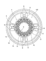
図2は本願の第1実施形態に係る光照射装置100の発光ユニット4の端面図である。管きょ内に配置され、発光ユニット4の端部を覆うカバー4a(図1参照)を取り外した状態の発光ユニット4の端面を示している。
FIG. 2 is an end view of the light emitting unit 4 of the
発光ユニット4は概略円筒状に形成された本体9を有している。本体9の外面には光源として発光ダイオード(LED)10が取り付けられている。この発光ダイオード10はケーブル8を介して地上から電力の供給を受け発光する。本体9はポリカーボネートから形成された透明な保護筒12によって覆われ、保護されている。発光ユニット4の本体9の端部と保護筒12の端部は、発光ユニット4の端部を覆うカバー4a(図1参照)に固定されている。
The light emitting unit 4 has a main body 9 formed in a substantially cylindrical shape. A light emitting diode (LED) 10 is attached to the outer surface of the main body 9 as a light source. The
発光ユニット4の本体9は、同形状をした複数の単位部材11が周方向に複数結合して実質的に円筒状に構成されている。本第1実施形態においては、単位部材11を16個配置している。本体9は、単位部材11の数を選択することによって径方向の寸法が異なるものを容易に製造することができる。
The main body 9 of the light emitting unit 4 is configured substantially in a cylindrical shape by combining a plurality of
図2において、光照射装置100の径方向外側に実線で描かれた円は、管きょの径方向内側部分を構成する配管用銅管13と管きょの径方向外側部分を構成する配管用鋼管14を示している。また、光照射装置100の径方向外側に破線で描かれた円は、ライナー15を示している。
In FIG. 2, a circle drawn by a solid line on the radially outer side of the
光照射装置100は、アーム5の先端に取り付けられた車輪6によって、ライナー15と発光ユニット4との距離を保ちながら、ライナー15上をスムーズに移動することができる。また、発光ダイオード10が取り付けられた円筒状の発光ユニット4の本体9は、単位部材11の数を適切なものとすることで、管きょの径に適した径方向の寸法を有している。このように構成された光照射装置100を、管きょ内で順次移動させて発光ユニット4を発光させることで、未硬化のライナー15に万遍なく光を照射し、ライナー15全体をムラなく硬化させることができる。
The
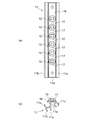
図3は本願の第1実施形態に係る光照射装置100の発光ユニット4を構成する単位部材11を示す図である。(a)は平面図、(b)は端面図である。
FIG. 3 is a view showing the
単位部材11は、光照射装置100の長手方向に長い棒状をしており、LED基板16を取り付けたベースプレート11aと、ベースプレート11aの一方の側に一体に形成された第1の結合部11bと、ベースプレート11aの他方の側に一体に形成された第2の結合部11cと、第1の結合部11bに一体に形成された一対の放熱フィン11d、11eと、を有している。単位部材11は、金属、プラスチック、セラミックスなど種々の材料から形成することができる。
The
ベースプレート11aは、光照射装置100の長手方向に長い長方形の板状をしている。発光ユニット4の本体9(図2参照)を構成した際に径方向外側(以下「本体9の径方向外側」とする。)となるベースプレート11aの面には、LED基板16が取り付けられている。LED基板16には、レンズ17に覆われた発光ダイオード10が長手方向に6個並んで取り付けられている。
The
第1の結合部11bは、断面が略逆C字型をして、単位部材11の長手方向に長い棒状をしている。言い換えれば、第1の結合部11bは、全長にわたって軸方向に延びるスリット(開放部)を形成した切り欠き円筒状をしている。第1の結合部11bは、ベースプレート11aと略同じ長さを有し、ベースプレート11aに沿って略平行で、発光ユニット4の本体9を構成した際に径方向内側(以下「本体9の径方向内側」とする。)となるベースプレート11aの面の一方の側に一体に形成されている。このように第1の結合部11bを本体9の径方向内側に配置することで、本体9の外面において、ベースプレート11aの面積を広くとり、周方向に隣り合うベースプレート11aの間の隙間を狭くすることができる。第1の結合部11bは、スリットが本体9の径方向外側になる向きでベースプレート11aに一体に形成されている。つまり、第1の結合部11bは、逆C字型断面の開放部が本体9の径方向外側となる向きでベースプレート11aに一体に形成されている。
The
第2の結合部11cは、断面が第1の結合部11bよりも小径のC字型をして、単位部材11の長手方向に長い棒状をしている。言い換えれば、第2の結合部11cは、第1の結合部11bよりも径寸法が小さく、全長にわたって軸方向に延びるスリット(開放部)を形成した切り欠き円筒状をしている。第2の結合部11cは、ベースプレート11a及び第1の結合部11bと略同じ長さを有している。第2の結合部11cは、ベースプレート11aに沿って略平行で、本体9の径方向内側となるベースプレート11aの面の第1の結合部11bとは反対側の部分に一体に形成されている。このように第2の結合部11cを本体9の径方向内側に配置することで、本体9の外面において、ベースプレート11aの面積を広くとり、周方向に隣り合うベースプレート11aの間の隙間を狭くすることができる。第2の結合部11cは、スリットが本体9の径方向内側になる向きでベースプレート11aと一体に形成されている。つまり、第2の結合部11cは、C字型断面の開放部が本体9の径方向内側となる向きでベースプレート11aに一体に形成されている。
The
第1の結合部11bの内径は、第2の結合部11cが内側に収まる寸法を有している。つまり、第1の結合部11bの内径寸法は、第2の結合部11cの外径寸法と略同じか、第2の結合部11cの外径寸法よりも大きいか、第2の結合部11cの外径寸法よりも僅かに小さいものとすることができる。隣り合う単位部材11の第2の結合部11cを第1の結合部11bの内側に収容した状態で、隣り合う単位部材11が相対的に角度を変えられる寸法とすることが望ましい。
The inner diameter of the
第1の結合部11bへの第2の結合部11cの挿入は、第1の結合部11bの端部から第2の結合部11cの端部を挿入し、スライドさせることにより行うことができる。また、第1の結合部11bのスリットに第2の結合部11cを押し込むことで第1の結合部11bを弾性変形させ、スリットを拡幅して第2の結合部11cを挿入した後、第1の結合部11bが弾性復帰するものとしても良い。
Insertion of the
一対の放熱フィン11d、11eは、それぞれ、単位部材11の長手方向に長い長方形の板状をしており、本体9の径方向内側となる第1の結合部11bの部分に一体に形成されている。一対の放熱フィン11d、11eは、図3(b)に示すように、長手方向に見たときに第1の結合部11bの略接線方向で本体9の径方向内側に延びるように形成されている。これにより、隣り合う単位部材11の放熱フィン11d、11eが干渉しないようにしている(図2参照)。放熱フィン11d、11eは、発光ダイオード10が発した熱を放熱する。
Each of the pair of
以上の構成により、本第1実施形態によれば、第1の結合部11bと第2の結合部11cを係合して複数の単位部材11を組み合わせるだけで、他の部材を必要とせず、容易に本体9を構成することができる。また、隣り合った単位部材11は所定の角度範囲内において自由な角度で結合可能なため、周方向に配置する単位部材11の数を自由に設定することができる。これにより、本第1実施形態によれば、製造に要する手間とコストを抑えながら、下水道管などの管きょの径に合わせた円筒状の発光ユニット4の製造が可能な光照射装置100を実現することができる。加えて、単位部材11は全長にわたって同一の断面形状をしているため、発光ユニット4の長さも自由に設定することができる。
With the above configuration, according to the first embodiment, only the plurality of
次に、本第1実施形態に係る光照射装置100の製造方法について説明する。本第1実施形態に係る光照射装置100は、発光ユニット4の本体9の製造工程に特徴を有し、その他の製造工程は従来の光照射装置100と同様に行うことができる。
Next, a method for manufacturing the
発光ユニット4の本体9の製造は、上記単位部材11を複数準備する工程と、補修対象となる管きょの径に合わせて単位部材11の個数を選択する工程と、選択した数の単位部材11を周方向に結合して円筒状の本体9を構成する工程と、を含む。
The manufacturing of the main body 9 of the light emitting unit 4 includes a step of preparing a plurality of the
これにより、製造に要する手間とコストを抑えながら、下水道管などの管きょの内径寸法に合わせた光照射装置100の製造が可能となる。
As a result, it is possible to manufacture the
<第2実施形態>
次に、本願の第2実施形態について図4を参照しながら説明する。本第2実施形態に係る光照射装置は、発光ユニット204の本体209を除いて、上記第1実施形態と同様である。したがって、重複する説明は省略し、発光ユニット204の本体209について説明する。
Second Embodiment
Next, a second embodiment of the present application will be described with reference to FIG. The light irradiation apparatus according to the second embodiment is the same as that of the first embodiment except for the
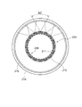
図4は、本第2実施形態に係る光照射装置の発光ユニット204の端面図である。上記第1実施形態の図2に対応する。
FIG. 4 is an end view of the
本第2実施形態に係る発光ユニット204の本体209は、上記第1実施形態よりも径の大きい管きょ218に対応すべく、32個の単位部材211を組み合わせて構成されている。単位部材211は、本体209の内側に延びる放熱フィンを有さない点において、上記第1実施形態とは異なっている。
The
光源としての発光ダイオード210は、円筒状の本体209の周方向において、単位部材211に1つおきに取り付けられている。このような構成であっても、発光ダイオード210の光がライナー215の断面全体に照射されるように発光ユニット204の本体209の径寸法を設定すれば良い。図4においては、発光ダイオード210が光を照射する角度範囲を60°としている。図4に示すように、各発光ダイオード210が照射した光が、管きょ218の内周面又はライナー215の外周面において重なるように、単位部材211の数を選択し、発光ダイオード210の配置を決めれば良い。本第2実施形態に係る光照射装置は、上記第1実施形態と同様に製造することができる。
Every other
以上のように、本第2実施形態によれば、製造に要する手間とコストを抑えながら、下水道管などの管きょの径に合わせた製造が可能な光照射装置、及び、光照射装置の製造方法を実現することができる。また、単位部材211は全長にわたって同一の断面形状をしているため、発光ユニット204の長さも自由に設定することができる。
As described above, according to the second embodiment, the light irradiation device that can be manufactured in accordance with the diameter of the pipe such as a sewer pipe, and the light irradiation device can be manufactured while suppressing labor and cost required for the manufacture. A manufacturing method can be realized. Moreover, since the
なお、本願発明の理解を助けるため、具体的な実施形態について詳細な説明を行ったが、本願発明はこれに限られず、種々の変更、改良等が可能である。 In addition, in order to assist the understanding of the present invention, specific embodiments have been described in detail, but the present invention is not limited thereto, and various changes and improvements can be made.
例えば、単位部材の数は、16個及び32個に限られず、3個以上の任意の数とすることができる。 For example, the number of unit members is not limited to 16 and 32, and can be any number of 3 or more.
また、複数の単位部材は、上記実施形態のように全て同じ形状をしていることが望ましいが、これに限られない。 Moreover, although it is desirable that the plurality of unit members have the same shape as in the above embodiment, the present invention is not limited to this.
また、第1の結合部と第2の結合部は、所定の角度範囲内において任意の角度で単位部材同士を結合できるものであれば、上記実施形態に示したものに限らず、採用することができる。例えば、第1の結合部と第2の結合部のいずれか一方が凸部、もう一方が凹部を形成し、第1の結合部と第2の結合部とで抜き差し蝶番を構成するものとしても良い。 The first coupling portion and the second coupling portion are not limited to those shown in the above embodiment as long as the unit members can be coupled at an arbitrary angle within a predetermined angle range. Can do. For example, one of the first coupling portion and the second coupling portion may be a convex portion, the other may be a concave portion, and the first coupling portion and the second coupling portion may constitute an insertion / extraction hinge. good.
2 カメラ
3 連結部材
4、204 発光ユニット
4a カバー
5 アーム
6 車輪
7 温度センサー
8 ケーブル
9、209 本体
10、210 発光ダイオード
11、211 単位部材
11a ベースプレート
11b 第1の結合部
11c 第2の結合部
11d、11e 放熱フィン
12 保護筒
13 配管用銅管
14 配管用鋼管
15、215 ライナー
16 LED基板
17 レンズ
100 光照射装置
218 管きょ
2
Claims (9)
複数の単位部材を周方向に結合して構成された概略円筒状の本体と、前記本体の外面に設けられた複数の光源と、を備えた発光ユニットを有し、
前記複数の単位部材は、それぞれ、前記外面を形成したベースプレートと、前記ベースプレートに一体に形成された第1の結合部と、前記ベースプレートに一体に形成され、隣り合う前記単位部材の前記第1の結合部に係合した第2の結合部とを備えることを特徴とする光照射装置。 A light irradiation device for irradiating light to a liner impregnated with a photocurable resin in a tube,
A substantially cylindrical main body configured by connecting a plurality of unit members in the circumferential direction; and a plurality of light sources provided on an outer surface of the main body, and a light emitting unit comprising:
Each of the plurality of unit members includes a base plate that forms the outer surface, a first coupling portion that is integrally formed with the base plate, and the first unit of the adjacent unit members that are integrally formed with the base plate. A light irradiation apparatus comprising: a second coupling portion engaged with the coupling portion.
前記第2の結合部は、前記ベースプレートに対して、隣り合うもう一方の前記単位部材の側で前記本体の径方向内側に形成されていることを特徴とする請求項1又は2に記載の光照射装置。 The first coupling portion is formed on the radially inner side of the main body on the side of one unit member adjacent to the base plate,
3. The light according to claim 1, wherein the second coupling portion is formed radially inward of the main body on the side of the other adjacent unit member with respect to the base plate. Irradiation device.
前記第1及び第2の単位部材それぞれの、一方の長辺部に沿って内径側に内向きに延びて一体に形成された第1の結合部と、他方の長辺部に沿って内径側に内向きに延びて一体に形成され、隣り合う第2及び第1の単位部材の前記第1の結合部と連結された第2の結合部と、
前記第1の単位部材の外径側表面に固設されたLEDと、
から成ることを特徴とする発光ユニット。 A cylindrical main body formed of a plurality of first and second unit members each in the form of a long rectangular plate, wherein the first unit members and the second unit members are alternately juxtaposed side by side; ,
Each of the first and second unit members extends inwardly toward the inner diameter side along one long side part, and is integrally formed along the other long side part. A second coupling portion that is integrally formed extending inwardly and connected to the first coupling portion of the adjacent second and first unit members;
LEDs fixed on the outer diameter side surface of the first unit member;
A light emitting unit comprising:
管きょ内において光硬化性樹脂を含浸したライナーに光を照射する光照射装置の製造方法であって、
前記外面を形成するベースプレートと、前記ベースプレートに一体に形成された第1の結合部と、前記ベースプレートに一体に形成され、隣り合う前記単位部材の前記第1の結合部に係合する第2の結合部と、を備えた単位部材を複数準備する工程と、
前記管きょの径に合わせて前記単位部材の数を選択する工程と、
選択した数の前記単位部材を周方向に結合して前記本体を構成する工程と、を含むことを特徴とする光照射装置の製造方法。 A substantially cylindrical main body configured by connecting a plurality of unit members in the circumferential direction; and a plurality of light sources provided on an outer surface of the main body, and a light emitting unit comprising:
A method of manufacturing a light irradiation device for irradiating light to a liner impregnated with a photocurable resin in a tube,
A base plate that forms the outer surface, a first coupling portion that is integrally formed with the base plate, and a second that is integrally formed with the base plate and engages with the first coupling portion of the adjacent unit members. A step of preparing a plurality of unit members including a coupling portion;
Selecting the number of unit members according to the diameter of the tube;
And combining the selected number of the unit members in the circumferential direction to form the main body.
Priority Applications (1)
| Application Number | Priority Date | Filing Date | Title |
|---|---|---|---|
| JP2015179650A JP2017053473A (en) | 2015-09-11 | 2015-09-11 | Light irradiation device, light-emitting unit, and method for manufacturing light irradiation device |
Applications Claiming Priority (1)
| Application Number | Priority Date | Filing Date | Title |
|---|---|---|---|
| JP2015179650A JP2017053473A (en) | 2015-09-11 | 2015-09-11 | Light irradiation device, light-emitting unit, and method for manufacturing light irradiation device |
Publications (1)
| Publication Number | Publication Date |
|---|---|
| JP2017053473A true JP2017053473A (en) | 2017-03-16 |
Family
ID=58320663
Family Applications (1)
| Application Number | Title | Priority Date | Filing Date |
|---|---|---|---|
| JP2015179650A Pending JP2017053473A (en) | 2015-09-11 | 2015-09-11 | Light irradiation device, light-emitting unit, and method for manufacturing light irradiation device |
Country Status (1)
| Country | Link |
|---|---|
| JP (1) | JP2017053473A (en) |
Cited By (2)
| Publication number | Priority date | Publication date | Assignee | Title |
|---|---|---|---|---|
| CN114236670A (en) * | 2021-12-27 | 2022-03-25 | 绵阳惠科光电科技有限公司 | Backlight structure and display device |
| KR20240009851A (en) * | 2022-07-14 | 2024-01-23 | 가부시키가이샤 쇼난 고세이쥬시 세이사쿠쇼 | Irradiation Facility |
-
2015
- 2015-09-11 JP JP2015179650A patent/JP2017053473A/en active Pending
Cited By (4)
| Publication number | Priority date | Publication date | Assignee | Title |
|---|---|---|---|---|
| CN114236670A (en) * | 2021-12-27 | 2022-03-25 | 绵阳惠科光电科技有限公司 | Backlight structure and display device |
| CN114236670B (en) * | 2021-12-27 | 2024-04-02 | 绵阳惠科光电科技有限公司 | Backlight structure and display device |
| KR20240009851A (en) * | 2022-07-14 | 2024-01-23 | 가부시키가이샤 쇼난 고세이쥬시 세이사쿠쇼 | Irradiation Facility |
| KR102700070B1 (en) | 2022-07-14 | 2024-08-27 | 가부시키가이샤 쇼난 고세이쥬시 세이사쿠쇼 | Irradiation Facility |
Similar Documents
| Publication | Publication Date | Title |
|---|---|---|
| JP6360475B2 (en) | Light irradiation device | |
| JP6099212B2 (en) | Light irradiation device | |
| JP6605464B2 (en) | Curing apparatus, photoreactive system, and method | |
| JP6017573B2 (en) | Multiple light collection and lens combination with co-located focus for curing optical fibers | |
| KR101389223B1 (en) | Led lamp for homogeneously illuminating hollow bodies | |
| CN103319100B (en) | Ultraviolet curing equipment and method for optical fiber coating | |
| US20200003354A1 (en) | Curing device for curing a pipe liner | |
| KR101890938B1 (en) | Curing apparatus employing angled uvleds | |
| US20100260945A1 (en) | System and methods for optical curing using a reflector | |
| JP2008175381A (en) | Curing / rehabilitation device with LED | |
| US20140185302A1 (en) | Lighting device | |
| NZ591472A (en) | Lighting apparatus with heat dissipating plate and frame with a lens spanning an aperture for emitted light | |
| KR20160075591A (en) | Apparatus for radiant energy curing of a coating | |
| US20160327701A1 (en) | Device for hardening a coating on an inner wall of a conduit having an oval cross section | |
| JP6465828B2 (en) | Light irradiation device | |
| JP2019021602A (en) | Lens unit and vehicular lighting fixture | |
| JP5538467B2 (en) | Lens unit, light irradiation unit and light irradiation device | |
| US20190193113A1 (en) | Irradiation systems for curing targets, related curing systems, and related methods | |
| JP4193947B2 (en) | UV irradiation equipment | |
| DK201870118A1 (en) | Curing device for curing a pipe liner | |
| KR20130021720A (en) | Uv-led curing device | |
| KR101737321B1 (en) | Condensing lighting device | |
| KR101539723B1 (en) | Small diameter pipe internal investigation unit | |
| JP2004092818A (en) | In-pipe repair machine | |
| JP2008311137A (en) | Line type light guide and line illumination device |