JP2017073473A - Terminal structure of transformer - Google Patents
Terminal structure of transformer Download PDFInfo
- Publication number
- JP2017073473A JP2017073473A JP2015199825A JP2015199825A JP2017073473A JP 2017073473 A JP2017073473 A JP 2017073473A JP 2015199825 A JP2015199825 A JP 2015199825A JP 2015199825 A JP2015199825 A JP 2015199825A JP 2017073473 A JP2017073473 A JP 2017073473A
- Authority
- JP
- Japan
- Prior art keywords
- transformer
- terminal
- cable
- load
- earthquake
- Prior art date
- Legal status (The legal status is an assumption and is not a legal conclusion. Google has not performed a legal analysis and makes no representation as to the accuracy of the status listed.)
- Pending
Links
Images

Landscapes
- Coils Of Transformers For General Uses (AREA)
Abstract
Description
この発明は、変圧器の端子構造、特に、強い地震力に対しても破損しない端子部を持つ低圧乾式変圧器の端子構造に関するものである。 The present invention relates to a terminal structure of a transformer, and more particularly to a terminal structure of a low-voltage dry transformer having a terminal portion that is not damaged even by a strong seismic force.
従来の変圧器においては、変圧器の端子部の破損は主に配線の余長不足により発生するものと考えられており、ケーブル振動の荷重評価に基づく強度設計は考慮されていない。
端子部の破損を防止した変圧器は、例えば特許文献1(第6図)に示すように、変圧器1次側端子を軟銅線で構成することにより、外力に対する伸び率を確保し、断線を抑えて振動を吸収している。また、例えば特許文献1(第5図)に示すように、変圧器2次側端子に接続する引き出し線を分割することにより、分割した引き出し線相互の振動の位相を変え、引き出し線の振動によりコイルに印加される力を抑制している。
In the conventional transformer, it is considered that the breakage of the terminal portion of the transformer is mainly caused by the shortage of the wiring length, and the strength design based on the load evaluation of the cable vibration is not taken into consideration.
For example, as shown in Patent Document 1 (FIG. 6), the transformer that prevents the terminal portion from being damaged is constituted by an annealed copper wire on the primary side of the transformer so as to ensure an elongation rate with respect to an external force and to prevent disconnection. It suppresses and absorbs vibration. For example, as shown in Patent Document 1 (FIG. 5), by dividing the lead wire connected to the transformer secondary terminal, the phase of vibration between the split lead wires is changed, and the vibration of the lead wire is changed. The force applied to the coil is suppressed.
従来の低圧乾式変圧器では、変圧器全体の耐震性について考慮されているものの、地震時の端子部に発生する荷重が考慮されていないため、地震力や配線の方法によっては、ケーブル振動により端子部が破損する可能性があった。
この発明は上記のような課題を解決するためになされたものであり、地震発生時に破損しない端子部を持つ変圧器を得ることを目的とする。
In conventional low-voltage dry transformers, although the earthquake resistance of the entire transformer is considered, the load generated at the terminal part during an earthquake is not taken into account, so depending on the seismic force and wiring method, the terminal may be caused by cable vibration. The part could be damaged.
The present invention has been made to solve the above-described problems, and an object thereof is to obtain a transformer having a terminal portion that is not damaged when an earthquake occurs.
この発明は、変圧器鉄心と固定された支持金具、碍子を介して前記支持金具と固定され配線用ケーブルが接続される変圧器端子、変圧器コイルから引き出され前記変圧器端子に接続された引き出し線を備えた変圧器の端子構造において、前記変圧器端子及び前記碍子は変形しない固さを持つ部材で構成して、地震時に受ける前記変圧器端子の荷重が前記碍子を介して前記変圧器端子と固定される前記支持金具に伝わるように構成するとともに、地震時の荷重を受けても前記引き出し線を介して前記変圧器コイルが破損されないよう前記支持金具は前記変圧器端子を固定する位置での水平方向の変位が所定値以下となるようにしたものである。 The present invention relates to a support fitting fixed to a transformer core, a transformer terminal fixed to the support fitting via a lever and connected to a wiring cable, a drawer drawn from a transformer coil and connected to the transformer terminal In the terminal structure of the transformer provided with a wire, the transformer terminal and the insulator are made of a member having a hardness that does not deform, and the load of the transformer terminal that is received during an earthquake is transmitted through the insulator through the transformer terminal. The support metal fitting is fixed at the position where the transformer terminal is fixed so that the transformer coil is not damaged through the lead wire even if it receives a load during an earthquake. The horizontal displacement is set to be equal to or less than a predetermined value.
この発明によれば、強い地震力に対しても破損しない端子部を持つ変圧器を得ることができる。 According to the present invention, it is possible to obtain a transformer having a terminal portion that is not damaged even by a strong seismic force.
実施の形態1.
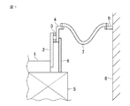
以下、この発明の実施の形態1を図1に基づいて説明する。図1は、この発明に係る実施の形態1における変圧器の端子構造を示す概念図である。
図1において、変圧器の端子部は鉄心1と、鉄心に取り付けられた支持金具2と、碍子3を介して支持金具2に取り付けられた変圧器端子4からなる。変圧器端子4は、コイル5からの引き出し線6に接続されている。また、変圧器端子4は配線用のケーブル7に接続されており、また、ケーブル7の他端は鉄心1を有する変圧器を収容する盤の筐体8に設けた盤内端子9に接続されている。盤内端子9は外部端子(図示せず)を介して外部回路に接続される。そして、盤内端子9は、固縛で代用することができる。
A first embodiment of the present invention will be described below with reference to FIG. 1 is a conceptual diagram showing a terminal structure of a transformer according to
In FIG. 1, the terminal portion of the transformer includes an
ケーブル7の長さには、地震による変圧器端子4の変位や、盤内端子9の変位を吸収可能な余長を確保する。また、変圧器端子4および盤内端子9等のケーブル端を固定点とした振り子運動が発生しないよう、ケーブル7の余長は最小限に留める。更に、ケーブル7の素材およびケーブル7の配線経路は、フレキシブル導体等の容易に変形可能なものを選定し、変圧器端子4と盤内端子9の間に張力が働かないようにする。
The length of the
変圧器端子4の固有振動数は、地震の卓越振動数より十分大きい20Hz以上となるように設計する。固有振動数評価の際は、ケーブル7の重みを付加した状態での固有振動を考慮する。また、変圧器の鉄心1、支持金具2、碍子3と一体となった固有振動を考慮する。盤内端子9についても、ケーブル7の重みを付加した状態での固有振動数、および筐体8と一体となった固有振動数が20Hz以上となるように設計する。
The natural frequency of the
地震時に変圧器端子4にかかる荷重は、余長を持った容易に変形可能なケーブル7の振動を元に以下のように評価する。
ケーブルの重さをm、ケーブル端の固有振動数をf0、地震の振動数をf、ケーブルの余長をl、地震力をA[G]とし、ケーブル端に作用する最大の力Fを次式として評価する。
F=m×8πf0×(l+A×9.8/(2πf)2)×f
地震の振動数が1〜10Hzの中間で卓越する場合を想定し、f=1[Hz]とf=10[Hz]とでFを評価し、いずれか大きい方の力を評価荷重とする。
The load applied to the
The cable's weight is m, the natural frequency of the cable end is f0, the frequency of the earthquake is f, the extra length of the cable is l, the seismic force is A [G], and the maximum force F acting on the cable end is Evaluate as an expression.
F = m × 8πf 0 × (l + A × 9.8 / (2πf) 2 ) × f
Assuming that the seismic frequency is dominant in the middle of 1 to 10 Hz, F is evaluated at f = 1 [Hz] and f = 10 [Hz], and the larger force is set as the evaluation load.
ケーブル7端に働く力は、変圧器端子4と盤内端子9で分担するが、変圧器端子4が全ての力を負担すると仮定して設計する。また、盤内端子9についても、同様に全ての力を負担すると仮定する。
仮にケーブル7の重さをm=0.5[kg]、変圧器端子4の固有振動数をf0=20[Hz]、余長をl=0.05[m]、地震力を2[G]とすると、
f=1[Hz]時にF=138[N]=14.1[kg重]となる。
また、f=10[Hz]時にF=139[N]=14.2[kg重]となるため、14.2[kg]の荷重を評価荷重とする。
The force acting on the end of the
Temporarily, the weight of the
When f = 1 [Hz], F = 138 [N] = 14.1 [kg weight].
Further, since F = 139 [N] = 14.2 [kg weight] at f = 10 [Hz], a load of 14.2 [kg] is set as the evaluation load.
ケーブル7から変圧器端子4に上記の荷重が加わった時に、コイル5および引き出し線6を破損させないよう、変圧器を以下のように設計する。
変圧器端子4と支持金具2とを2箇所以上で、もしくは平面状に固定し、変圧器端子4に加わる荷重が支持金具2に伝わるようにする。変圧器端子4および碍子3は、荷重で変形しない固さを持つ部材で構成することにより、変圧器端子4への荷重が支持金具2に伝わるようにする。
支持金具2は、軟鋼等の素材で構成するものとし、全ての荷重を受けても変形しないように固く設計する。具体的には、変圧器端子4を固定する位置での水平方向の変位が所定値以下、具体的には1mm以下となるように設計する。また、上下方向の変位は1mmと比較して無視できる大きさとなるように設計する。
The transformer is designed as follows so that the
The
The
引き出し線6は、導電性に優れた銅の素材で構成するものとし、支持金具2と比較して十分柔らかい設計とする。具体的には、支持金具2の変形により変圧器端子4が水平方向に1mm程度移動してもコイル5が破損しないように設計する。設計例としては、支持金具2と比較して水平方向の変形に対するバネ剛性が1/10以下となるように引き出し線6を設計する。このようにすると、コイル5にかかる荷重が変圧器端子4にかかる荷重の1/10以下となる。
The
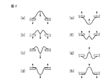
次に、地震時の挙動について、図1および図2、図3で説明する。図2はケーブル動作の詳細な説明図であり、図3は端子部動作の詳細な説明図である。
地震が発生した時、図1のケーブル7はケーブル端から外力を受け、地震に含まれる振動数において振動するものとして評価する。ケーブル7は容易に変形可能なため、図2の(a)、(d)、(e)、(h)のように最大に変形している時に限り、ケーブル端に張力が作用する。また、ケーブル端に張力が作用した時に限り、ケーブル7には外力が働き、振動方向が変わる。
Next, behavior during an earthquake will be described with reference to FIGS. 1, 2, and 3. FIG. 2 is a detailed explanatory view of the cable operation, and FIG. 3 is a detailed explanatory view of the terminal portion operation.
When an earthquake occurs, the
具体的には、図1の変圧器端子4および盤内端子9等のケーブル端の固有振動数が20Hz以上となるように設計しているため、ケーブル端は建屋床面と一体となって振動するものとして評価する。
図2の(a)のように、移動によりケーブル7にたるみがなくなると、ケーブル7に張力が発生しケーブル全体が移動する。図2の(b)、(c)のように、ケーブル端が減速を開始すると、ケーブル7はたるんでケーブル端を通り越して移動を続ける。図2の(d)のように、ケーブル7のたるみがなくなった時点でケーブル7はケーブル端から外力を受けて、移動の方向が反転する。
Specifically, since the natural frequency of the cable ends such as the
As shown in FIG. 2A, when there is no slack in the
図2の(d)および(e)のように、ケーブル7の移動方向が反転する時、ケーブル7の運動はケーブル端の反発力により支配される。ケーブル端は20Hz以上の固有振動数f0を持つように設計されているため、20Hzと比較してゆっくり移動してきたケーブルの力を瞬時に吸収して、逆方向に解放する。この時にケーブル端に加わる力は、振動数f0の単振動として評価できるため、ケーブル端に加わる最大の力をFとして、F×sin(2πf0t)のように変化する。方向が反転するまでに発生する力積は2F/2πf0である。ケーブル7の重さをm、外力が作用していない状態でのケーブル7の速度をvとすると、力積はケーブル7の運動量変化2mvと等しくなるため、F=mv×2πf0となる。
As shown in FIGS. 2D and 2E, when the moving direction of the
ケーブル7が外力を受けていない状態では、ケーブル7に張力が働いていないため、ケーブル7の運動は自由運動に類似する。地震の振動数をf 、ケーブルの余長をl、地震力をA[G]とすると、平衡点からのケーブル7の移動距離は、最大でも余長l+ケーブル端の移動距離となる。また、ケーブル端の移動距離は、地震力Aと地震の振動数fで決まり、A×9.8/{2πf}2となる。余長lに左記を加えた移動距離を移動時間l/4fで除することにより、ケーブル7の速度をv=(l+A×9.8/{2πf}2)×4fと評価する。
よって、ケーブル端に加わる最大の力Fは、次式で評価できる。
F=m×8πf0×(l+A×9.8/{2πf}2)×f
この評価式に地震力Aやケーブル端の固有振動数f0、ケーブル余長l、ケーブルの重さm、等に数値を入力し、f=1[Hz]およびf=10[Hz]でのFを評価することにより、想定した地震力での最大荷重が求まる。
In a state where the
Therefore, the maximum force F applied to the cable end can be evaluated by the following equation.
F = m × 8πf 0 × (l + A × 9.8 / {2πf} 2 ) × f
Enter numerical values for the seismic force A, cable end natural frequency f0, cable surplus length l, cable weight m, etc. into this evaluation formula, and F at f = 1 [Hz] and f = 10 [Hz]. The maximum load with the assumed seismic force can be obtained by evaluating.
上記最大荷重が変圧器端子4に印加されている時、図3に示すように変圧器端子4や碍子3は変形せず、荷重は支持金具2に印加される。変圧器端子4に荷重が加わった時、引き出し線9にも荷重が加わるが、引き出し線9は支持金具2と比較して十分柔らかく設計しているため、支持金具2がほぼ全ての荷重を負担する。支持金具2は、全ての荷重を負担しても水平方向に所定値以下、具体的には1mm以下の変形となるように設計しているため、引き出し線9の変形も1mm程度として評価可能である。コイル5は、引き出し線9の変形が1mm以内であれば破損しないように設計しているため、荷重印加時にコイル5は破損しない。
上記のように構成することにより、強い地震力に対しても破損しない端子部を持つ低圧乾式変圧器を得ることができる。
When the maximum load is applied to the
By comprising as mentioned above, the low voltage | pressure dry type transformer which has a terminal part which is not damaged with respect to a strong seismic force can be obtained.
なお、本発明は、その発明の範囲内において、実施の形態を適宜、変形、省略することが可能である。 In the present invention, the embodiments can be appropriately modified and omitted within the scope of the invention.
1 鉄心、 2 支持金具、 3 碍子、 4 変圧器端子、5 コイル、
6 引き出し線、 7 ケーブル、 8 筐体、 9 盤内端子。
1
6 Lead wire, 7 Cable, 8 Housing, 9 Board terminal.
Claims (4)
Priority Applications (1)
| Application Number | Priority Date | Filing Date | Title |
|---|---|---|---|
| JP2015199825A JP2017073473A (en) | 2015-10-08 | 2015-10-08 | Terminal structure of transformer |
Applications Claiming Priority (1)
| Application Number | Priority Date | Filing Date | Title |
|---|---|---|---|
| JP2015199825A JP2017073473A (en) | 2015-10-08 | 2015-10-08 | Terminal structure of transformer |
Publications (1)
| Publication Number | Publication Date |
|---|---|
| JP2017073473A true JP2017073473A (en) | 2017-04-13 |
Family
ID=58537842
Family Applications (1)
| Application Number | Title | Priority Date | Filing Date |
|---|---|---|---|
| JP2015199825A Pending JP2017073473A (en) | 2015-10-08 | 2015-10-08 | Terminal structure of transformer |
Country Status (1)
| Country | Link |
|---|---|
| JP (1) | JP2017073473A (en) |
Citations (7)
| Publication number | Priority date | Publication date | Assignee | Title |
|---|---|---|---|---|
| JPS5540548U (en) * | 1978-09-07 | 1980-03-15 | ||
| JPS575856Y2 (en) * | 1976-09-20 | 1982-02-03 | ||
| JPS5846425U (en) * | 1981-09-22 | 1983-03-29 | 株式会社東芝 | molded transformer |
| JPS633129Y2 (en) * | 1981-06-16 | 1988-01-26 | ||
| JPH0134333Y2 (en) * | 1981-04-22 | 1989-10-19 | ||
| JP2005032814A (en) * | 2003-07-08 | 2005-02-03 | Japan Ae Power Systems Corp | Earthquake-resistant structure transformer |
| JP2009147196A (en) * | 2007-12-17 | 2009-07-02 | Hitachi Industrial Equipment Systems Co Ltd | Earthquake-resistant mold transformer |
-
2015
- 2015-10-08 JP JP2015199825A patent/JP2017073473A/en active Pending
Patent Citations (7)
| Publication number | Priority date | Publication date | Assignee | Title |
|---|---|---|---|---|
| JPS575856Y2 (en) * | 1976-09-20 | 1982-02-03 | ||
| JPS5540548U (en) * | 1978-09-07 | 1980-03-15 | ||
| JPH0134333Y2 (en) * | 1981-04-22 | 1989-10-19 | ||
| JPS633129Y2 (en) * | 1981-06-16 | 1988-01-26 | ||
| JPS5846425U (en) * | 1981-09-22 | 1983-03-29 | 株式会社東芝 | molded transformer |
| JP2005032814A (en) * | 2003-07-08 | 2005-02-03 | Japan Ae Power Systems Corp | Earthquake-resistant structure transformer |
| JP2009147196A (en) * | 2007-12-17 | 2009-07-02 | Hitachi Industrial Equipment Systems Co Ltd | Earthquake-resistant mold transformer |
Similar Documents
| Publication | Publication Date | Title |
|---|---|---|
| JP5089206B2 (en) | Linear vibrator | |
| KR101783370B1 (en) | Earthquake-proof mold transformer | |
| US11411480B2 (en) | Linear vibration actuator motor | |
| US20180241293A1 (en) | Vibration motor | |
| ATE301254T1 (en) | VIBRATION ABSORTER | |
| CN112105577A (en) | Vibration damping system and elevator device | |
| KR101349616B1 (en) | Earthquake-proofing switchboard | |
| KR102155297B1 (en) | Smart seismic device of distribution panel, solar connection panel, motor control panel | |
| US20180236488A1 (en) | Vibration motor | |
| JP2008259264A (en) | Vibration power generator | |
| JP5082044B2 (en) | Seismic isolation device | |
| JP6632355B2 (en) | Damping device | |
| JPS6379304A (en) | Polarized electromagnet device | |
| JP2017073473A (en) | Terminal structure of transformer | |
| KR101739101B1 (en) | The distribution panel including a cable supporting apparatus of earthquake-proof function | |
| JP2016051850A (en) | Stationary induction apparatus | |
| US4140868A (en) | Vibration damper for cables | |
| KR102264956B1 (en) | Distribution panel | |
| JP6303846B2 (en) | Vibration power generator | |
| JP2016167910A (en) | Wiring installation structure | |
| JP2014229380A (en) | Anti-dropping device | |
| JP5943873B2 (en) | Anti-sway tool | |
| KR102187326B1 (en) | Seismic device of distribution panel, solar connection panel, motor control panel | |
| KR102264955B1 (en) | Distribution panel | |
| JPS6138355Y2 (en) |
Legal Events
| Date | Code | Title | Description |
|---|---|---|---|
| A621 | Written request for application examination |
Free format text: JAPANESE INTERMEDIATE CODE: A621 Effective date: 20171110 |
|
| A977 | Report on retrieval |
Free format text: JAPANESE INTERMEDIATE CODE: A971007 Effective date: 20181022 |
|
| A131 | Notification of reasons for refusal |
Free format text: JAPANESE INTERMEDIATE CODE: A131 Effective date: 20181204 |
|
| A521 | Request for written amendment filed |
Free format text: JAPANESE INTERMEDIATE CODE: A523 Effective date: 20190125 |
|
| RD04 | Notification of resignation of power of attorney |
Free format text: JAPANESE INTERMEDIATE CODE: A7424 Effective date: 20190605 |
|
| A131 | Notification of reasons for refusal |
Free format text: JAPANESE INTERMEDIATE CODE: A131 Effective date: 20190702 |
|
| A521 | Request for written amendment filed |
Free format text: JAPANESE INTERMEDIATE CODE: A523 Effective date: 20190821 |
|
| A02 | Decision of refusal |
Free format text: JAPANESE INTERMEDIATE CODE: A02 Effective date: 20200128 |