JP2017077832A - Steering device - Google Patents
Steering device Download PDFInfo
- Publication number
- JP2017077832A JP2017077832A JP2015207442A JP2015207442A JP2017077832A JP 2017077832 A JP2017077832 A JP 2017077832A JP 2015207442 A JP2015207442 A JP 2015207442A JP 2015207442 A JP2015207442 A JP 2015207442A JP 2017077832 A JP2017077832 A JP 2017077832A
- Authority
- JP
- Japan
- Prior art keywords
- power supply
- power
- supply path
- auxiliary
- drive circuit
- Prior art date
- Legal status (The legal status is an assumption and is not a legal conclusion. Google has not performed a legal analysis and makes no representation as to the accuracy of the status listed.)
- Pending
Links
Images



Landscapes
- Power Steering Mechanism (AREA)
Abstract
【課題】モータの出力の低下を抑制できるステアリング装置を提供する。【解決手段】EPSのECU4は、第1ECU4aおよび第2ECU4bを有している。第1ECU4aは、モータ20に電力を供給する第1駆動回路50と、バッテリ40から第1駆動回路50への給電のオンオフを切り替える第1電源リレー60と、第1駆動回路50および第1電源リレー60を制御する第1制御回路70とを有している。また、第1ECU4aは、バッテリ40から第2駆動回路100への給電のオンオフを切り替える第1補助電源リレー61を有している。第2ECU4bは、第1ECU4aと同様に、第2駆動回路100と、第2電源リレー110と、第2制御回路120と、バッテリ41から第1駆動回路50への給電のオンオフを切り替える第2補助電源リレー111とを有している。【選択図】図2A steering device capable of suppressing a decrease in the output of a motor is provided. An EPS ECU 4 has a first ECU 4a and a second ECU 4b. The first ECU 4a includes a first drive circuit 50 that supplies electric power to the motor 20, a first power relay 60 that switches ON/OFF of power supply from the battery 40 to the first drive circuit 50, the first drive circuit 50 and the first power relay. and a first control circuit 70 for controlling 60 . The first ECU 4 a also has a first auxiliary power relay 61 that switches ON/OFF of power supply from the battery 40 to the second drive circuit 100 . As with the first ECU 4a, the second ECU 4b includes a second drive circuit 100, a second power relay 110, a second control circuit 120, and a second auxiliary power supply that switches on and off power supply from the battery 41 to the first drive circuit 50. and a relay 111 . [Selection drawing] Fig. 2
Description
本発明は、ステアリング装置に関する。 The present invention relates to a steering device.
従来、車両用のステアリング装置には、モータを駆動源として操舵機構にアシスト力を付与する電動パワーステアリング装置(EPS)がある。このモータの動作を制御する電子制御装置(ECU)は、複数のスイッチング素子を有する駆動回路と、複数のスイッチング素子のオンオフを制御するモータ制御信号を出力する制御回路とを備えている。このようなECUには、たとえばバッテリとECUとの間に設けられる給電経路上に電源リレーが設けられたものがある。たとえば、駆動回路にショート故障等の異常が発生した場合には、電源リレーをオフ状態にすることにより、駆動回路とモータとの間を通電不能に遮断する。 2. Description of the Related Art Conventionally, a vehicle steering apparatus includes an electric power steering apparatus (EPS) that applies assist force to a steering mechanism using a motor as a drive source. An electronic control unit (ECU) for controlling the operation of the motor includes a drive circuit having a plurality of switching elements and a control circuit for outputting a motor control signal for controlling on / off of the plurality of switching elements. Some of such ECUs are provided with a power relay on a power supply path provided between the battery and the ECU, for example. For example, when an abnormality such as a short circuit failure occurs in the drive circuit, the power supply relay is turned off to interrupt the drive circuit and the motor from being energized.
また、特許文献1に示すように、ECUを、2つの駆動回路および2つの給電経路を有する2系統の構成とすることで、ECUに冗長性を持たせたEPSもある。このEPSによれば、たとえば一方の駆動回路に異常が発生した場合でも、他方の駆動回路からモータに電力を供給することで、モータの駆動を継続できる。
In addition, as shown in
しかし、特許文献1のようなEPSでは、2系統の駆動回路のうち一方の系統の給電経路に異常が発生した場合、他方の系統の駆動回路のみでモータに電力を供給する必要がある。2系統の駆動回路からモータに電力を供給していた状態が、1系統の駆動回路からモータに電力を供給する状態となるため、モータへ供給される電力が通常時よりも減少する。このため、モータの出力も通常時よりも低下する。したがって、当該異常時には、本来要求されるアシスト力が得られないおそれがある。
However, in EPS like
本発明の目的は、モータの出力の低下を抑制できるステアリング装置を提供することである。 The objective of this invention is providing the steering device which can suppress the fall of the output of a motor.
上記目的を達成しうるステアリング装置は、複数相のモータコイルを有するモータと、車載される電源の電力を利用して、前記モータに駆動用の電力を供給する複数の駆動回路と、前記電源と前記複数の駆動回路との間をそれぞれ接続する複数の電力供給路と、前記電源と前記複数の駆動回路との間に設けられ、前記複数の電力供給路の間を全て遮断する第1の状態と、前記複数の電力供給路の間を少なくとも1つ接続する第2の状態との間で切り替える切り替え部と、前記複数の駆動回路および前記切り替え部の動作を制御することにより、前記モータへの給電を制御する少なくとも1つの制御部と、を備えている。前記制御部は、通常時には前記切り替え部を前記第1の状態に維持し、前記複数の電力供給路のうちいずれか1つに異常が生じた異常時には前記切り替え部を前記第1の状態から前記第2の状態へ切り替える。 A steering apparatus that can achieve the above object includes a motor having a plurality of phase motor coils, a plurality of drive circuits that supply power for driving to the motor by using power of a power source mounted on the vehicle, and the power source. A plurality of power supply paths that respectively connect the plurality of drive circuits, and a first state that is provided between the power source and the plurality of drive circuits and that blocks all of the plurality of power supply paths. And a switching unit that switches between the second state in which at least one of the plurality of power supply paths is connected, and the operation of the plurality of drive circuits and the switching unit, And at least one control unit that controls power feeding. The control unit maintains the switching unit in the first state in a normal state, and moves the switching unit from the first state to an abnormal state when an abnormality occurs in any one of the plurality of power supply paths. Switch to the second state.
この構成によれば、複数の電力供給路のうちいずれかに異常が生じた場合、切り替え部が第1の状態から第2の状態に切り替えられることにより、異常が生じた電力供給路は、正常な他の電力供給路と接続されることとなる。このため、本来ならば異常が生じた電力供給路から電力が供給される駆動回路は、正常な他の電力供給路から電力が供給される。このため、異常が発生した場合であれ、複数相のモータコイルへの給電が通常通り継続される。したがって、モータの出力の低下が抑えられる。 According to this configuration, when an abnormality occurs in any of the plurality of power supply paths, the switching section is switched from the first state to the second state, so that the power supply path in which the abnormality has occurred is normal. It will be connected to other power supply paths. For this reason, the drive circuit to which power is normally supplied from the power supply path in which an abnormality has occurred is supplied with power from another normal power supply path. For this reason, even if an abnormality occurs, power feeding to the motor coils of a plurality of phases is continued as usual. Therefore, a decrease in motor output can be suppressed.
上記のステアリング装置において、前記複数の電力供給路上にそれぞれ設けられ、これら電力供給路を開閉するスイッチを備え、前記切り替え部は、前記複数の電力供給路において、互いの前記スイッチの上流側の部分と下流側の部分との間を接続する複数の補助電力供給路と、前記複数の補助電力供給路にそれぞれ設けられ、これら補助電力供給路を開閉する補助スイッチと、を有し、前記制御部は、通常時には前記スイッチをオン、かつ前記補助スイッチをオフにした状態に維持することにより、前記切り替え部を前記第1の状態に維持し、前記複数の電力供給路のうちいずれか1つに異常が生じた異常時には、異常な電力供給路の前記スイッチの下流側と正常な電力供給路の前記スイッチの上流側とを接続する前記補助電力供給路の前記補助スイッチをオンすることにより、前記切り替え部を前記第2の状態に切り替えることが好ましい。 In the above steering apparatus, each of the plurality of power supply paths is provided with a switch that opens and closes the power supply paths, and the switching unit is a part of the plurality of power supply paths that is upstream of each of the switches. A plurality of auxiliary power supply paths connecting between the two and the downstream portion, and an auxiliary switch provided in each of the plurality of auxiliary power supply paths for opening and closing the auxiliary power supply paths, and the control unit Maintains the switching unit in the first state by keeping the switch on and the auxiliary switch off in a normal state, and sets the switch to any one of the plurality of power supply paths. When an abnormality occurs, before the auxiliary power supply path connecting the downstream side of the switch of the abnormal power supply path and the upstream side of the switch of the normal power supply path By turning on the auxiliary switch, it is preferable to switch the switching unit in the second state.
この構成によれば、いずれか1つの電力供給路で異常が発生することにより、異常が発生した電力供給路と対応する駆動回路への給電が遮断されたとき、その駆動回路への給電を継続すべく、正常な他の電力供給路のスイッチの上流側と異常が発生した電力供給路のスイッチの下流側との間の補助電力供給路の補助スイッチをオンにする。これにより、異常が発生した電力供給路には、正常な電力供給路から電力が供給されることとなり、異常が発生した電力供給路に対応する駆動回路への給電は継続される。 According to this configuration, when an abnormality occurs in any one of the power supply paths, when the power supply to the drive circuit corresponding to the power supply path where the abnormality has occurred is interrupted, the power supply to the drive circuit is continued. Therefore, the auxiliary switch of the auxiliary power supply path between the upstream side of the switch of the other normal power supply path and the downstream side of the switch of the power supply path where the abnormality has occurred is turned on. Thus, power is supplied from the normal power supply path to the power supply path in which the abnormality has occurred, and power supply to the drive circuit corresponding to the power supply path in which the abnormality has occurred is continued.
上記のステアリング装置において、前記複数の駆動回路は、前記モータに電力を供給する第1の駆動回路と、前記モータに電力を供給する第2の駆動回路と、を含み、前記複数の電力供給路は、前記電源と前記第1の駆動回路との間を接続する第1の電力供給路と、前記電源と前記第2の駆動回路との間を接続する第2の電力供給路と、を含み、前記複数のスイッチは、前記第1の電力供給路に設けられる第1のスイッチと、前記第2の電力供給路に設けられる第2のスイッチと、を含み、前記複数の補助電力供給路は、前記第1の電力供給路と前記第2の駆動回路との間を接続する第1の補助電力供給路と、前記第2の電力供給路と前記第1の駆動回路との間を接続する第2の補助電力供給路と、を含み、前記複数の補助スイッチは、前記第1の補助電力供給路に設けられる第1の補助スイッチと、前記第2の補助電力供給路に設けられる第2の補助スイッチと、を含むことが好ましい。 In the above steering apparatus, the plurality of drive circuits include a first drive circuit that supplies power to the motor and a second drive circuit that supplies power to the motor, and the plurality of power supply paths Includes a first power supply path that connects the power source and the first drive circuit, and a second power supply path that connects the power source and the second drive circuit. The plurality of switches include a first switch provided in the first power supply path and a second switch provided in the second power supply path, and the plurality of auxiliary power supply paths are , Connecting the first auxiliary power supply path connecting the first power supply path and the second drive circuit, and connecting the second power supply path and the first drive circuit. A second auxiliary power supply path, wherein the plurality of auxiliary switches are Preferably includes a first auxiliary switch provided on one of the auxiliary power supply path, and the second of the second auxiliary switch provided in the assist power supply path, the.
この構成によれば、第2の電力供給路における電源と第2のスイッチとの間の部分に断線などの異常が発生した場合、第1の補助スイッチがオンされることにより、第1の補助電力供給路への給電が許容される。これにより、第1の補助電力供給路を介して第2の駆動回路に給電が継続される。また、第1の供給路における電源と第1のスイッチとの間の部分に断線などの異常が発生した場合、第2の補助スイッチがオンされることにより第2の補助電力供給路への給電が許容される。これにより、第2の補助電力供給路を介して第1の駆動回路に給電が継続される。 According to this configuration, when an abnormality such as a disconnection occurs in a portion between the power source and the second switch in the second power supply path, the first auxiliary switch is turned on, thereby causing the first auxiliary switch to be turned on. Power supply to the power supply path is allowed. Thereby, electric power feeding is continued to the 2nd drive circuit via the 1st auxiliary power supply way. In addition, when an abnormality such as a disconnection occurs in a portion between the power supply and the first switch in the first supply path, power is supplied to the second auxiliary power supply path by turning on the second auxiliary switch. Is acceptable. Thereby, electric power feeding is continued to the 1st drive circuit via the 2nd auxiliary power supply way.
上記のステアリング装置において、前記電源は、第1の電源と、第2の電源と、を有し、前記第1の電源は、前記第1の電力供給路に接続され、前記第2の電源は、前記第2の電力供給路に接続されることが好ましい。 In the steering apparatus, the power source includes a first power source and a second power source, the first power source is connected to the first power supply path, and the second power source is The second power supply path is preferably connected.
この構成によれば、第1の電源は第1の駆動回路へ給電するために用いられ、第2の電源は第2の駆動回路へ給電するために用いられる。このため、第1の電源と第2の電源に要求される性能は、電源を1つしか設けない場合と比べて、ある程度低くすることができる。また、電源が冗長化されるため、第1の電源が故障した場合であっても、第2の電源によって第1の駆動回路および第2の駆動回路への給電が継続される。 According to this configuration, the first power supply is used to supply power to the first drive circuit, and the second power supply is used to supply power to the second drive circuit. For this reason, the performance required for the first power supply and the second power supply can be reduced to some extent as compared with the case where only one power supply is provided. In addition, since the power supply is made redundant, even when the first power supply fails, power supply to the first drive circuit and the second drive circuit is continued by the second power supply.
上記のステアリング装置において、前記複数の電力供給路上にそれぞれ設けられ、これら電力供給路を開閉するスイッチと、前記複数の電力供給路における前記スイッチと前記電源との間の部分を互いに接続するワイヤードオアを備え、前記制御部は、前記ワイヤードオアを介して給電されることが好ましい。 In the above steering apparatus, a wired OR that is provided on each of the plurality of power supply paths and that opens and closes the power supply paths, and that connects a portion between the switch and the power source in the plurality of power supply paths. It is preferable that the control unit is supplied with power through the wired OR.
この構成によれば、複数の電力供給路のうちいずれか1つが断線故障した場合であっても、制御部には残る電力供給路からワイヤードオアを介して直ちに給電される。たとえば、制御部が電源から直接給電されている場合には、その給電経路の途中で断線などが生じると、制御部は停止してしまう。そして、再度何らかの形でその制御部に給電が再開された場合には、その制御部を再度起動する必要が生じる。これに対し、ワイヤードオアから制御部に常時給電されることによって、制御部が一時的に停止すること(瞬断)が抑制される。 According to this configuration, even if any one of the plurality of power supply paths is broken, power is immediately supplied from the power supply path remaining in the control unit via the wired OR. For example, when the control unit is directly supplied with power from the power source, if the disconnection occurs in the middle of the power supply path, the control unit stops. When power supply to the control unit is resumed in some form again, the control unit needs to be activated again. On the other hand, by temporarily supplying power from the wired OR to the control unit, it is possible to prevent the control unit from temporarily stopping (instantaneous interruption).
上記のステアリング装置において、前記制御部は、前記複数の駆動回路にそれぞれ対応して設けられることが好ましい。
この構成によれば、制御部は自らの系統の駆動回路のみを駆動すればよいので、複数の系統の駆動回路を同時に制御しなくてよい分、各制御部の駆動回路を制御する演算負荷はそれぞれ低減される。
In the steering apparatus, the control unit is preferably provided corresponding to each of the plurality of drive circuits.
According to this configuration, since the control unit only needs to drive the drive circuit of its own system, it is not necessary to control the drive circuits of a plurality of systems at the same time. Each is reduced.
本発明のステアリング装置によれば、モータの出力の低下を抑制できる。 According to the steering device of the present invention, it is possible to suppress a decrease in the output of the motor.
以下、ステアリング装置をEPS(電動パワーステアリング装置)に具体化した一実施形態について説明する。
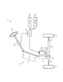
図1に示すように、EPS1は運転者のステアリングホイール10の操作に基づいて転舵輪15を転舵させる操舵機構2、運転者のステアリング操作を補助するアシスト機構3、およびアシスト機構3を制御するモータ制御装置としてのECU4を備えている。
Hereinafter, an embodiment in which the steering device is embodied as an EPS (electric power steering device) will be described.
As shown in FIG. 1, the
操舵機構2は、ステアリングホイール10およびステアリングホイール10と一体回転するステアリングシャフト11を備えている。ステアリングシャフト11は、ステアリングホイール10と連結されたコラムシャフト11aと、コラムシャフト11aの下端部に連結されたインターミディエイトシャフト11b、およびインターミディエイトシャフト11bの下端部に連結されたピニオンシャフト11cを有している。ピニオンシャフト11cの下端部はラックシャフト12に噛み合わされている。したがって、ステアリングシャフト11の回転運動は、ピニオンシャフト11cの先端に設けられたピニオンギヤとラックシャフト12に設けられたラックからなるラックアンドピニオン機構13を介して、ラックシャフト12の軸方向(図1の左右方向)の往復直線運動に変換される。当該往復直線運動がラックシャフト12の両端にそれぞれ連結されたタイロッド14を介して左右の転舵輪15にそれぞれ伝達されることにより、転舵輪15の転舵角が変更される。
The
アシスト機構3は、アシスト力の発生源であるモータ20を備えている。モータ20としては、たとえば、3相(U,V,W)の駆動電力に基づいて回転する3相ブラシレスモータが採用される。モータ20の回転軸21は、減速機構22を介してピニオンシャフト11cに連結されている。減速機構22はモータ20の回転を減速し、当該減速した回転力をピニオンシャフト11cに伝達する。すなわち、ステアリングシャフト11にモータ20の回転力(トルク)がアシスト力として付与されることにより、運転者のステアリング操作が補助される。
The assist mechanism 3 includes a
ECU4は、車載される2つのバッテリ40,41から電力が供給されることにより動作する。ECU4は、車両に設けられる各種のセンサの検出結果に基づいてモータ20を制御する。各種のセンサとしては、たとえばトルクセンサ30が設けられる。トルクセンサ30はコラムシャフト11aに設けられている。トルクセンサ30は、運転者のステアリング操作に伴いステアリングシャフト11に付与される操舵トルクτを検出する。ECU4はセンサの出力(たとえば操舵トルクτ)に基づいて、目標のアシスト力を設定し、実際のアシスト力が目標のアシスト力となるように、モータ20に供給される電流を制御する。
The
つぎに、ECU4について詳細に説明する。
図2に示すように、ECU4は、第1ECU4aおよび第2ECU4bを有している。第1ECU4aは、モータ20に電力を供給する第1駆動回路50と、バッテリ40から第1駆動回路50への給電のオンオフを切り替える第1電源リレー60と、第1駆動回路50および第1電源リレー60を制御する第1制御回路70とを有している。また、第2ECU4bは、モータ20に電力を供給する第2駆動回路100と、バッテリ41から第2駆動回路100への給電のオンオフを切り替える第2電源リレー110と、第2駆動回路100および第2電源リレー110を制御する第2制御回路120とを有している。バッテリ40はグランド40aに接地され、バッテリ41はグランド41aに接地されている。ECU4は、モータ20への電力の供給を制御することにより、モータ20の動作を制御する。
Next, the
As shown in FIG. 2, the
第1駆動回路50は、複数のスイッチング素子を有し、それらのスイッチング素子をオンまたはオフすることにより、バッテリ40からの直流電力を3相交流電力に変換する。すなわち、第1駆動回路50は、バッテリ40側に接続される上側FET(電界効果型トランジスタ)51u,51v,51wと、グランド側に接続される下側FET52u,52v,52wとを有している。第1駆動回路50は、上側FET51uと下側FET52uを直列に接続したハーフブリッジ53uと、上側FET51vと下側FET52vを直列に接続したハーフブリッジ53vと、上側FET51wと下側FET52wを直列に接続したハーフブリッジ53wとを並列に接続することにより設けられている。
The
第1電源リレー60は、バッテリ40と第1駆動回路50(上側FET51u,51v,51w)との間の給電経路C1上に設けられている。第1電源リレー60は、通常オン状態に維持される。給電経路C1において、断線故障やショート故障などの異常が生じた場合、第1電源リレー60はオフ状態へ切り替えられる。給電経路C1が遮断されることにより、バッテリ40からモータ20への給電も遮断される。
The first
第1制御回路70は、バッテリ40からの電力を一定の電圧に変換する定電圧回路71と、定電圧回路71から一定の電圧が印加されることにより駆動するCPU(中央処理装置)72とを有している。定電圧回路71は、バッテリ40,41の電圧値の大きさがどのようなものであっても、定電圧回路71からの出力電圧を一定にする。CPU72は、上側FET51u,51v,51wおよび下側FET52u,52v,52wのゲート電極にそれぞれ接続されている。CPU72は、たとえば車載されるセンサにより検出される操舵トルクτやモータ20の回転角などの状態量を取り込み、これらの状態量に基づいてモータ制御信号(電圧信号)を生成する。CPU72は、各ゲート電極にモータ制御信号を印加することにより、上側FET51u,51v,51wおよび下側FET52u,52v,52wのオンオフを制御する。また、CPU72は、第1電源リレー60にも接続されている。CPU72は、第1電源リレー60のオンオフを制御する。
The
第2駆動回路100も第1駆動回路50と同様の構成を有している。第2駆動回路100は、バッテリ41からの直流電力を3相交流電力に変換する。第2駆動回路100は、上側FET101u,101v,101wおよび下側FET102u,102v,102wを有している。上側FET101uおよび下側FET102uはハーフブリッジ103uを、上側FET101vおよび下側FET102vはハーフブリッジ103vを、上側FET101wおよび下側FET102wはハーフブリッジ103wをそれぞれ構成する。
The
第2電源リレー110は、バッテリ41と第2駆動回路100(上側FET101u,101v,101w)との間の給電経路C2上に設けられている。第2電源リレー110は、通常オン状態に維持される。給電経路C2において、断線故障やショート故障などの異常が生じた場合(異常検出については説明を省略するが、異常検出手段からの信号に基づき異常判定する)、第2電源リレー110はオフ状態へ切り替えられる。給電経路C2が遮断されることにより、バッテリ41からモータ20への給電も遮断される。
The second
第2制御回路120は、第1制御回路70と同様の構成を有している。第2制御回路120も定電圧回路121およびCPU122を有している。CPU122は、上側FET101u,101v,101wおよび下側102u,102v,102wのゲート電極にそれぞれ接続されている。CPU122は車載されるセンサにより検出される状態量を取り込み、この状態量に基づいてモータ制御信号を生成することによって、上側FET101u,101v,101wおよび下側102u,102v,102wのオンオフを制御する。また、CPU122は、第2電源リレー110にも接続されている。CPU122は、第2電源リレー110のオンオフを制御する。
The
また、第1ECU4aは、バッテリ40から第2駆動回路100への給電のオンオフを切り替える第1補助電源リレー61を有している。また、第2ECU4bは、バッテリ41から第1駆動回路50への給電のオンオフを切り替える第2補助電源リレー111を有している。
Further, the
第1補助電源リレー61は、バッテリ40と第2駆動回路100(上側FET101u,101v,101w)との間の給電経路S1上に設けられている。給電経路S1は、給電経路C1におけるバッテリ40と第1電源リレー60との間(第1電源リレー60の上流側の部分)、および給電経路C2における第2電源リレー110と第2駆動回路100との間(第1電源リレー60の下流側の部分)に接続されている。第1補助電源リレー61は、通常オフ状態に維持される。すなわち、第1補助電源リレー61によって、通常はバッテリ40から第2駆動回路100への給電は遮断されている。
The first
給電経路C2(正確には、給電経路C2におけるバッテリ41と給電経路S1の接続点との間の給電経路C2a)において、断線故障(たとえばグランド41aの断線)やショート故障などの異常が生じた場合、第2電源リレー110はオン状態からオフ状態に切り替えられる。これに伴い、バッテリ41から第2駆動回路100への給電は遮断されるため、第2駆動回路100からモータ20へ電力は供給されなくなる。このとき、第1補助電源リレー61は、オン状態に切り替えられる。このため、バッテリ40と第2駆動回路100との間の給電経路S1の通電が許容され、バッテリ40から第2駆動回路100へ給電される。なお、CPU72によって第1補助電源リレー61のオンオフが制御される。CPU122は、一例として、第2電源リレー110がオフ状態であるにも関わらず、第2駆動回路100に電力が供給されないとき、給電経路C2に異常が発生したことを検出する。CPU122は、給電経路C2の異常が検出されたとき、その旨をCPU72に通知する。
When an abnormality such as a disconnection failure (for example, disconnection of the ground 41a) or a short-circuit failure occurs in the power supply path C2 (more precisely, the power supply path C2a between the
第2補助電源リレー111は、バッテリ41と第1駆動回路50(上側FET51u,51v,51w)との間の給電経路S2上に設けられている。給電経路S2は、給電経路C2におけるバッテリ41と第2電源リレー110との間(第2電源リレー110の上流側の部分)、および給電経路C1における第1電源リレー60と第1駆動回路との間(第2電源リレー110の下流側の部分)に接続されている。第2補助電源リレー111は、通常オフ状態に維持される。すなわち、第2補助電源リレー111によって、通常はバッテリ41から第1駆動回路50への給電は遮断されている。
The second
給電経路C1(正確には、給電経路C1におけるバッテリ40と給電経路S2の接続点との間の給電経路C1a)において、断線故障(たとえばグランド40aの断線)やショート故障などの異常が生じた場合、第1電源リレー60はオン状態からオフ状態に切り替えられる。これに伴い、バッテリ40から第1駆動回路50への給電は遮断されるため、第1駆動回路50からモータ20へ電力は供給されなくなる。このとき、第2補助電源リレー111は、オン状態に切り替えられる。このため、バッテリ41と第1駆動回路50との間の給電経路S2の通電が許容され、バッテリ41から第1駆動回路50へ給電される。なお、CPU122によって第2補助電源リレー111のオンオフが制御される。一例として、CPU72は、第1電源リレー60がオフ状態にあるにも関わらず、第1駆動回路50に電力が給電されないとき、給電経路C1に異常が発生したことを検出する。CPU72は、給電経路C1の異常が検出されたとき、その旨をCPU122に通知する。
When an abnormality such as a disconnection failure (for example, disconnection of the ground 40a) or a short-circuit failure occurs in the power supply path C1 (more precisely, the power supply path C1a between the
また、ECU4は、ダイオードオア80を有している。ダイオードオア80は、給電経路C1におけるバッテリ40と第1ECU4aとの間と、給電経路C2におけるバッテリ41と第2ECU4bとの間とを接続する給電経路C3上に設けられている。ダイオードオア80は、2つのダイオード81,82を有している。ダイオード81とダイオード82とは、互いに反対向きに配置されている。ダイオード81は、バッテリ40から第1制御回路70および第2制御回路120への給電を許容する向きに設けられている。ダイオード82は、バッテリ41から第1制御回路70および第2制御回路120への給電を許容する向きに設けられている。また、給電経路C3におけるダイオード81とダイオード82との間は、給電経路C4を介して第1制御回路70に接続され、給電経路C5を介して第2制御回路120に接続されている。ダイオードオア80は、バッテリ40およびバッテリ41のうち電圧の高い方からの電力が第1制御回路70および第2制御回路120へ供給されることを許容する。
The
つぎに、ECU4の動作について詳しく説明する。まず給電経路C2に何ら故障が生じていない通常時の動作について説明し、次に給電経路C2に何らかの故障が生じた異常時の動作について説明する。
Next, the operation of the
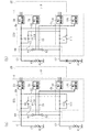
図3(a)に示すように、通常時は、第1電源リレー60および第2電源リレー110はオン状態に維持される。このため、第1ECU4aでは、バッテリ40から第1電源リレー60を介して第1駆動回路50に給電される。また、第2ECU4bでは、バッテリ41から第2電源リレー110を介して第2駆動回路100に給電される。なお、バッテリ40およびバッテリ41のうち、電圧値が大きいほうの電力が第1制御回路70および第2制御回路120に供給される。第1制御回路70および第2制御回路120は、第1駆動回路50および第2駆動回路100の各FETのスイッチングを制御することにより、モータ20へ供給される電力を制御する。
As shown in FIG. 3A, the first
つぎに、図3(b)に示すように、たとえば、給電経路C2におけるバッテリ41と第2ECU4bとの間で断線故障が発生した場合には、バッテリ41から第2ECU4bへの給電が遮断される。このため、第2駆動回路100はモータ20に電力を供給することができなくなる。
Next, as shown in FIG. 3B, for example, when a disconnection failure occurs between the
しかし、給電経路C2におけるバッテリ41と第2ECU4bとの間で断線故障が生じたとき、第1制御回路70(CPU72)によって、第1補助電源リレー61がオフ状態からオン状態に切り替えられることにより、バッテリ40から第2ECU4bに給電される。言い換えれば、バッテリ40から給電されている第1ECU4aから第1補助電源リレー61(給電経路S1)を介して第2ECU4bへと電力が供給される。このため、第2駆動回路100からモータ20に電力を継続して供給することができる。
However, when a disconnection failure occurs between the
このため、通常時と同様に、異常時も第1制御回路70および第2制御回路120は、第1駆動回路50および第2駆動回路100の2系統を介してモータ20への給電を継続できる。したがって、異常時であれ、モータ20により、本来要求されるアシスト力が発揮される。
For this reason, similarly to the normal time, the
ところで、給電経路C2におけるバッテリ41と第2ECU4bとの間で断線故障が発生した場合には、第2制御回路120は、第2電源リレー110をオフ状態にする。たとえば第1補助電源リレー61がオン状態に切り替えられることにより給電経路S1での給電が許容される場合に、何らかの異常が解消されるとき、第2電源リレー110がオン状態に維持されていると、バッテリ41から第2ECU4bへの給電が再開されることが想定される。この場合、第2ECU4bには、バッテリ40およびバッテリ41の両方から電力が流れ込むこととなり、本来想定される電力よりも大きな電力が供給されることとなる。このため、バッテリ41と第2ECU4bとの間で何らかの異常が発生した場合、第2制御回路120は第2電源リレー110をオフ状態にしておくことが好ましい。なお、何らかの異常としては、たとえば断線故障やバッテリと配線との間の接触不良などが挙げられる。
By the way, when a disconnection failure occurs between the
なお、給電経路C2aで断線故障が生じた場合に限らず、給電経路C1aで断線故障が生じた場合も同様である。すなわち、給電経路C1aで断線故障が生じた場合には、第2補助電源リレー111がオフ状態からオン状態に切り替えられることにより、バッテリ40の代わりにバッテリ41から第1ECU4aへ給電される。これにより、通常時も異常時も同様に、モータ20により、本来要求されるアシスト力が発揮される。なお、給電経路C1におけるバッテリ40と第1ECU4aとの間で断線故障が発生した場合、第1制御回路70は、第1電源リレー60をオフ状態にする。
The same applies not only when a disconnection failure occurs in the power supply path C2a but also when a disconnection failure occurs in the power supply path C1a. That is, when a disconnection failure occurs in the power supply path C1a, power is supplied from the
また、第1駆動回路50および第2駆動回路100にそれぞれ対応して第1制御回路70および第2制御回路120が設けられている。このため、1つの制御回路で2つの駆動回路(第1駆動回路50および第2駆動回路100)を制御する場合と比べて、第1制御回路70および第2制御回路120の演算負荷はそれぞれ低減される。複数の系統の駆動回路を同時に制御しなくてもよいためである。
Further, a
つぎに、ECU4に設けられるダイオードオア80の動作について説明する。通常時、ダイオードオア80は、バッテリ40およびバッテリ41のうち、電圧の高い方の電力が、第1制御回路70および第2制御回路120へ給電されることを許容する。また、たとえば給電経路C2aで断線故障が発生した場合、バッテリ41の電圧はダイオードオア80に印加されないので、直ちにバッテリ40から第1制御回路70および第2制御回路120へそれぞれ給電される。これに対し、たとえば給電経路C1aで断線故障が発生した場合には、バッテリ40の電圧はダイオードオア80に印加されないので、直ちにバッテリ41から第1制御回路70および第2制御回路120へそれぞれ給電される。このように、第1制御回路70および第2制御回路120は、バッテリ40およびバッテリ41のいずれか一方から給電される。
Next, the operation of the diode OR 80 provided in the
本実施形態の効果を説明する。
(1)バッテリ40と第2ECU4bとの間に給電経路S1が設けられている。このため、給電経路C2aが遮断された場合、第1補助電源リレー61がオン状態に切り替えられることにより、給電経路S1を介してバッテリ40から第2ECU4bへの給電が継続される。また、バッテリ41と第1ECU4aとの間に給電経路S2が設けられている。このため、給電経路C1aが遮断された場合も、第2補助電源リレー111がオン状態に切り替えられることにより、給電経路S2を介してバッテリ41から第1ECU4aへの給電が継続される。このため、通常時も異常時も同様に、第1駆動回路50および第2駆動回路100からモータ20に給電されることとなり、モータ20により要求されるアシスト力が発揮される。
The effect of this embodiment will be described.
(1) A power feeding path S1 is provided between the
(2)給電経路C1aで断線故障が発生することによりバッテリ40から第1ECU4aへの給電が行われない場合も、給電経路C2aで断線故障が発生することによりバッテリ41から第2ECU4bへの給電が行われない場合も、第1制御回路70および第2制御回路120には、ダイオードオア80を介してバッテリ40およびバッテリ41のいずれか一方から直ちに給電される。ダイオードオア80を介して第1制御回路70および第2制御回路120へ常時電力が供給される。ダイオードオア80を設けず、第1制御回路70がバッテリ40から直接給電されるようにした場合、その給電経路で断線が生じると直ちに第1制御回路70への給電が停止する。このため、第1制御回路70は停止する。何らかの手段によって第1制御回路70へ再度給電されたとしても、わずかな時間であれ第1制御回路70への給電が途切れる、いわゆる瞬断が生じる。また、第1制御回路70を再度起動するための時間が必要となってしまう。これに対し、本実施形態では、第1制御回路70および第2制御回路120には、バッテリ40またはバッテリ41のいずれか一方から常に給電されるため、瞬断が発生することが抑制される。また、第1制御回路70および第2制御回路120を再度立ち上げる必要もない。
(2) Even when power is not supplied from the
本実施形態は次のように変更してもよい。なお、以下の他の実施形態は、技術的に矛盾しない範囲において、互いに組み合わせることができる。
・本実施形態におけるバッテリ40,41は、同一品であってもよいし、電圧値や容量が異なるバッテリであってもよい。
The present embodiment may be modified as follows. The following other embodiments can be combined with each other within a technically consistent range.
The
・本実施形態では、給電経路C1におけるバッテリ40と第1ECU4aとの間で断線故障が発生した場合には、第1制御回路70は、第1電源リレー60をオフ状態にしたが、これに限らない。バッテリ40と第1ECU4aとの間の給電の再開が問題とならない場合、第1制御回路70は、第1電源リレー60をオン状態に維持してもよい。また、同様に、第2制御回路120は、第2電源リレー110をオン状態に維持してもよい。なお、第1電源リレー60および第2電源リレー110は設けなくてもよい。
In the present embodiment, when a disconnection failure occurs between the
・本実施形態では、2つのバッテリ40,41が設けられたが、これに限らない。たとえば、図4に示すように、1つのバッテリ40のみを設けてもよい。この場合、たとえば給電経路C1上の分岐点Bに給電経路C2が接続される。給電経路C1における分岐点Bと第1電源リレー60との間の部分、または給電経路C2における分岐点Bと第2電源リレー110との間の部分で断線などの異常が発生した場合であっても、第1補助電源リレー61または第2補助電源リレー111が閉じられることにより、第1駆動回路50および第2駆動回路100への給電は継続される。
-In this embodiment, although the two
・本実施形態では、ダイオードオア80が設けられたが、これは設けられなくてもよい。ダイオードオア80を設けない場合、第1制御回路70はバッテリ40と第1電源リレー60との間に接続され、第2制御回路120はバッテリ41と第2電源リレー110との間に接続される(図5参照)。
In the present embodiment, the diode OR 80 is provided, but this may not be provided. When the diode OR 80 is not provided, the
・本実施形態では、第1制御回路70と第2制御回路120とが設けられたが、これに限らない。たとえば、図4に示すように、第1制御回路70の1つのみが設けられてもよい。この場合、第1制御回路70は、第1駆動回路50および第2駆動回路100の各FETのオンオフを制御する。また、第1制御回路70は、第1電源リレー60および第2電源リレー110、ならびに第1補助電源リレー61および第2補助電源リレー111のオンオフを制御する。すなわち、駆動回路ごとにそれぞれ制御回路を設ける必要はなく、全ての駆動回路をまとめて制御する制御回路があればよい。また、全ての駆動回路をまとめて制御する制御回路は、第1ECU4aに限らず、第2ECU4bに設けられてもよい。また、全ての駆動回路をまとめて制御する制御回路は、第1ECU4aおよび第2ECU4bに設けるのに限らず、ECU4の内部に設ければよい。
-In this embodiment, although the
・本実施形態では、第1ECU4aおよび第2ECU4bの2系統からモータ20に電力を供給したが、図5に示すように、第1ECU4aおよび第2ECU4bに加え、第3ECU4cの3系統からモータ20に電力を供給するようにしてもよい。この場合、たとえば車両にはバッテリ40,41に加え、バッテリ42が設けられる。第3ECU4cは、モータ20に電力を供給する第3駆動回路130と、バッテリ42から第3駆動回路130への給電のオンオフを切り替える第3電源リレー140と、第3駆動回路130および第3電源リレー140を制御する第3制御回路150とを有している。また、第1ECU4aは、補助電源リレー61および補助電源リレー62を有している。補助電源リレー61は、第1ECU4aから第2ECU4bへ電力を供給するための給電経路上に、補助電源リレー62は、第1ECU4aから第3ECU4cへ電力を供給するための給電経路上に設けられている。第2ECU4bは、補助電源リレー111および補助電源リレー112を有している。補助電源リレー111は、第2ECU4bから第1ECU4aへ電力を供給するための給電経路上に、補助電源リレー112は、第2ECU4bから第3ECU4cへ電力を供給するための給電経路上に設けられている。第3ECU4cは、補助電源リレー141および補助電源リレー142を有している。補助電源リレー141は、第3ECU4cから第1ECU4aへ電力を供給するための給電経路上に、補助電源リレー142は、第3ECU4cから第2ECU4bへ電力を供給するための給電経路上に設けられている。すなわち、第1ECU4a、第2ECU4b、および第3ECU4cは、各補助電源リレーをオンすることにより、相互に給電し合うことが可能である。なお、4系統以上のモータに対応する場合、3系統の場合と同様に、ECU4の構成を多重化すればよい。バッテリ42は、系統数と同数だけ設けてもよいし、図4に示されているように、1つだけ設けてもよい。複数のバッテリを設ける場合、1つ1つのバッテリに要求される性能を低くすることができる。なお、図2に示される場合と同様にダイオードオア80を設ける場合、ダイオードオア80は、各給電経路における各バッテリと各ECUとの間を互いに接続する給電経路上に設ければよい。
In this embodiment, power is supplied to the
・本実施形態では、バッテリ40に対応してグランド40aが設けられ、バッテリ41に対応してグランド41aが設けられたが、これに限らない。たとえば、バッテリ40およびバッテリ41に共通したグランドが設けられてもよい。
In the present embodiment, the ground 40a is provided corresponding to the
・本実施形態では、第1電源リレー60および第2電源リレー110、ならびに第1補助電源リレー61および第2補助電源リレー111が用いられたが、これらは電気的なスイッチ(たとえばFET)であってもよいし、機械的なスイッチであってもよい。
In the present embodiment, the first
・本実施形態では、ECU4は1つのモータ20に電力を供給したが、2つ以上のモータに電力を供給するようにしてもよい。
・本実施形態では、EPSに具体化して示したが、これに限らない。たとえば、ステアバイワイヤ(SBW)に適用してもよい。また、SBWに限らず、後輪操舵装置や4輪操舵装置(4WS)として具体化してもよい。なお、SBWの場合、ラックを有するラックシャフト12に限らず、ラックを有さないシャフトを転舵シャフトとして採用してもよい。この場合、たとえばボールねじ機構を用いることにより、転舵シャフトに転舵力を付与する。
In the present embodiment, the
-In this embodiment, although it showed concretely in EPS, it is not restricted to this. For example, it may be applied to steer-by-wire (SBW). Moreover, you may actualize as not only SBW but a rear-wheel steering apparatus or a four-wheel steering apparatus (4WS). In the case of SBW, not only the
1…EPS、2…操舵機構、3…アシスト機構、4…ECU、4a…第1ECU、4b…第2ECU、10…ステアリングホイール、11…ステアリングシャフト、11a…コラムシャフト、11b…インターミディエイトシャフト、11c…ピニオンシャフト、12…ラックシャフト、13…ラックアンドピニオン機構、14…タイロッド、15…転舵輪、20…モータ、21…回転軸、22…減速機構、30…トルクセンサ、40,41,42…バッテリ(電源)、40a,41a,42a…グランド、50…第1駆動回路(駆動回路)、51u,51v,51w…上側FET、52u,52v,52w…下側FET、53u,53v,53w…ハーフブリッジ、60…第1電源リレー(スイッチ)、61…第1補助電源リレー(切り替え部、補助スイッチ)、62…第3補助電源リレー(切り替え部、補助スイッチ)、70…第1制御回路(制御部)、71…定電圧回路、72…CPU、80…ダイオードオア、81,82…ダイオード、100…第2駆動回路(駆動回路)、101u,101v,101w…上側FET、102u,102v,102w…下側FET、103u,103v,103w…ハーフブリッジ、110…第2電源リレー(スイッチ)、111…第2補助電源リレー(切り替え部、補助スイッチ)、120…第2制御回路(制御部)、121…定電圧回路、122…CPU、130…第3駆動回路(駆動回路)、150…第3制御回路(制御部)、τ…操舵トルク、B…分岐点、C1〜C5…給電経路(電力供給路)、S1,S2…給電経路(補助電力供給路)。
DESCRIPTION OF
Claims (6)
車載される電源の電力を利用して、前記モータに駆動用の電力を供給する複数の駆動回路と、
前記電源と前記複数の駆動回路との間をそれぞれ接続する複数の電力供給路と、
前記電源と前記複数の駆動回路との間に設けられ、前記複数の電力供給路の間を全て遮断する第1の状態と、前記複数の電力供給路の間を少なくとも1つ接続する第2の状態との間で切り替える切り替え部と、
前記複数の駆動回路および前記切り替え部の動作を制御することにより、前記モータへの給電を制御する少なくとも1つの制御部と、を備え、
前記制御部は、通常時には前記切り替え部を前記第1の状態に維持し、前記複数の電力供給路のうちいずれか1つに異常が生じた異常時には前記切り替え部を前記第1の状態から前記第2の状態へ切り替えるステアリング装置。 A motor having a multi-phase motor coil;
A plurality of drive circuits for supplying power for driving to the motor using the power of the power source mounted on the vehicle;
A plurality of power supply paths respectively connecting the power source and the plurality of drive circuits;
A first state that is provided between the power source and the plurality of drive circuits, and that blocks all of the plurality of power supply paths; and a second state that connects at least one of the plurality of power supply paths. A switching unit that switches between states,
And at least one control unit that controls power supply to the motor by controlling operations of the plurality of drive circuits and the switching unit, and
The control unit maintains the switching unit in the first state in a normal state, and moves the switching unit from the first state to an abnormal state when an abnormality occurs in any one of the plurality of power supply paths. A steering device for switching to the second state.
前記複数の電力供給路上にそれぞれ設けられ、これら電力供給路を開閉するスイッチを備え、
前記切り替え部は、
前記複数の電力供給路において、互いの前記スイッチの上流側の部分と下流側の部分との間を接続する複数の補助電力供給路と、
前記複数の補助電力供給路にそれぞれ設けられ、これら補助電力供給路を開閉する補助スイッチと、を有し、
前記制御部は、通常時には前記スイッチをオン、かつ前記補助スイッチをオフにした状態に維持することにより、前記切り替え部を前記第1の状態に維持し、
前記複数の電力供給路のうちいずれか1つに異常が生じた異常時には、異常な電力供給路の前記スイッチの下流側と正常な電力供給路の前記スイッチの上流側とを接続する前記補助電力供給路の前記補助スイッチをオンすることにより、前記切り替え部を前記第2の状態に切り替えるステアリング装置。 The steering apparatus according to claim 1, wherein
Provided on each of the plurality of power supply paths, comprising a switch for opening and closing these power supply paths,
The switching unit is
In the plurality of power supply paths, a plurality of auxiliary power supply paths that connect between the upstream part and the downstream part of the switches,
An auxiliary switch that is provided in each of the plurality of auxiliary power supply paths and opens and closes these auxiliary power supply paths;
The control unit maintains the switching unit in the first state by normally maintaining the switch on and the auxiliary switch off.
The auxiliary power that connects the downstream side of the switch in the abnormal power supply path and the upstream side of the switch in the normal power supply path when an abnormality occurs in any one of the plurality of power supply paths A steering device that switches the switching unit to the second state by turning on the auxiliary switch of the supply path.
前記複数の駆動回路は、前記モータに電力を供給する第1の駆動回路と、前記モータに電力を供給する第2の駆動回路と、を含み、
前記複数の電力供給路は、前記電源と前記第1の駆動回路との間を接続する第1の電力供給路と、前記電源と前記第2の駆動回路との間を接続する第2の電力供給路と、を含み、
前記複数のスイッチは、前記第1の電力供給路に設けられる第1のスイッチと、前記第2の電力供給路に設けられる第2のスイッチと、を含み、
前記複数の補助電力供給路は、前記第1の電力供給路と前記第2の駆動回路との間を接続する第1の補助電力供給路と、前記第2の電力供給路と前記第1の駆動回路との間を接続する第2の補助電力供給路と、を含み、
前記複数の補助スイッチは、前記第1の補助電力供給路に設けられる第1の補助スイッチと、前記第2の補助電力供給路に設けられる第2の補助スイッチと、を含むステアリング装置。 The steering apparatus according to claim 2, wherein
The plurality of drive circuits include: a first drive circuit that supplies power to the motor; and a second drive circuit that supplies power to the motor;
The plurality of power supply paths include a first power supply path that connects the power supply and the first drive circuit, and a second power that connects the power supply and the second drive circuit. A supply channel,
The plurality of switches include a first switch provided in the first power supply path, and a second switch provided in the second power supply path,
The plurality of auxiliary power supply paths include a first auxiliary power supply path that connects the first power supply path and the second drive circuit, the second power supply path, and the first power supply path. A second auxiliary power supply path connecting between the driving circuit and the driving circuit,
The plurality of auxiliary switches includes a first auxiliary switch provided in the first auxiliary power supply path and a second auxiliary switch provided in the second auxiliary power supply path.
前記電源は、第1の電源と、第2の電源と、を有し、
前記第1の電源は、前記第1の電力供給路に接続され、
前記第2の電源は、前記第2の電力供給路に接続されるステアリング装置。 The steering apparatus according to claim 3, wherein
The power source includes a first power source and a second power source,
The first power source is connected to the first power supply path,
The second power supply is a steering device connected to the second power supply path.
前記複数の電力供給路上にそれぞれ設けられ、これら電力供給路を開閉するスイッチと、
前記複数の電力供給路における前記スイッチと前記電源との間の部分を互いに接続するワイヤードオアを備え、
前記制御部は、前記ワイヤードオアを介して給電されるステアリング装置。 In the steering device according to any one of claims 1 to 4,
A switch provided on each of the plurality of power supply paths, for opening and closing the power supply paths;
A wired OR for connecting portions between the switch and the power source in the plurality of power supply paths to each other,
The control unit is a steering device to which power is supplied via the wired OR.
前記制御部は、前記複数の駆動回路にそれぞれ対応して設けられるステアリング装置。 In the steering device according to any one of claims 1 to 5,
The control unit is a steering device provided corresponding to each of the plurality of drive circuits.
Priority Applications (1)
| Application Number | Priority Date | Filing Date | Title |
|---|---|---|---|
| JP2015207442A JP2017077832A (en) | 2015-10-21 | 2015-10-21 | Steering device |
Applications Claiming Priority (1)
| Application Number | Priority Date | Filing Date | Title |
|---|---|---|---|
| JP2015207442A JP2017077832A (en) | 2015-10-21 | 2015-10-21 | Steering device |
Publications (1)
| Publication Number | Publication Date |
|---|---|
| JP2017077832A true JP2017077832A (en) | 2017-04-27 |
Family
ID=58665957
Family Applications (1)
| Application Number | Title | Priority Date | Filing Date |
|---|---|---|---|
| JP2015207442A Pending JP2017077832A (en) | 2015-10-21 | 2015-10-21 | Steering device |
Country Status (1)
| Country | Link |
|---|---|
| JP (1) | JP2017077832A (en) |
Cited By (6)
| Publication number | Priority date | Publication date | Assignee | Title |
|---|---|---|---|---|
| CN111942463A (en) * | 2019-05-17 | 2020-11-17 | 株式会社电装 | Electric drive unit |
| WO2021117683A1 (en) * | 2019-12-11 | 2021-06-17 | 日立Astemo株式会社 | Motor drive control device |
| US11760284B2 (en) | 2019-12-17 | 2023-09-19 | Denso Corporation | Electronic control unit and power supply system |
| US20230391395A1 (en) * | 2022-06-07 | 2023-12-07 | Robert Bosch Gmbh | Method for Operating a Control Device for Controlling an Electric Motor, in Particular a Steering System |
| DE102022103808B4 (en) | 2022-02-17 | 2025-03-06 | Audi Aktiengesellschaft | Steering system structure and vehicle with a steering system structure |
| WO2025135024A1 (en) * | 2023-12-18 | 2025-06-26 | 株式会社デンソー | Motor control device |
Citations (7)
| Publication number | Priority date | Publication date | Assignee | Title |
|---|---|---|---|---|
| JP2004168258A (en) * | 2002-11-22 | 2004-06-17 | Toyoda Mach Works Ltd | Steering gear for vehicle |
| JP2004216928A (en) * | 2003-01-09 | 2004-08-05 | Honda Motor Co Ltd | Steering system with redundant system |
| JP2004276833A (en) * | 2003-03-18 | 2004-10-07 | Toyoda Mach Works Ltd | Vehicle steering system |
| JP2007153107A (en) * | 2005-12-05 | 2007-06-21 | Toyota Motor Corp | Power steering power control device |
| JP2009029196A (en) * | 2007-07-25 | 2009-02-12 | Denso Corp | Electric power steering device |
| JP2014221600A (en) * | 2013-05-13 | 2014-11-27 | トヨタ自動車株式会社 | Electric power steering device |
| US20140350794A1 (en) * | 2013-05-23 | 2014-11-27 | Caterpillar Inc. | Managing Steering with Short From Battery to Ground |
-
2015
- 2015-10-21 JP JP2015207442A patent/JP2017077832A/en active Pending
Patent Citations (7)
| Publication number | Priority date | Publication date | Assignee | Title |
|---|---|---|---|---|
| JP2004168258A (en) * | 2002-11-22 | 2004-06-17 | Toyoda Mach Works Ltd | Steering gear for vehicle |
| JP2004216928A (en) * | 2003-01-09 | 2004-08-05 | Honda Motor Co Ltd | Steering system with redundant system |
| JP2004276833A (en) * | 2003-03-18 | 2004-10-07 | Toyoda Mach Works Ltd | Vehicle steering system |
| JP2007153107A (en) * | 2005-12-05 | 2007-06-21 | Toyota Motor Corp | Power steering power control device |
| JP2009029196A (en) * | 2007-07-25 | 2009-02-12 | Denso Corp | Electric power steering device |
| JP2014221600A (en) * | 2013-05-13 | 2014-11-27 | トヨタ自動車株式会社 | Electric power steering device |
| US20140350794A1 (en) * | 2013-05-23 | 2014-11-27 | Caterpillar Inc. | Managing Steering with Short From Battery to Ground |
Cited By (12)
| Publication number | Priority date | Publication date | Assignee | Title |
|---|---|---|---|---|
| CN111942463A (en) * | 2019-05-17 | 2020-11-17 | 株式会社电装 | Electric drive unit |
| JP2020185964A (en) * | 2019-05-17 | 2020-11-19 | 株式会社デンソー | Electric driving device |
| JP7156168B2 (en) | 2019-05-17 | 2022-10-19 | 株式会社デンソー | electric drive |
| JP2022164738A (en) * | 2019-05-17 | 2022-10-27 | 株式会社デンソー | electric drive |
| US11511794B2 (en) | 2019-05-17 | 2022-11-29 | Denso Corporation | Electric driver device |
| WO2021117683A1 (en) * | 2019-12-11 | 2021-06-17 | 日立Astemo株式会社 | Motor drive control device |
| JPWO2021117683A1 (en) * | 2019-12-11 | 2021-06-17 | ||
| US11760284B2 (en) | 2019-12-17 | 2023-09-19 | Denso Corporation | Electronic control unit and power supply system |
| DE102022103808B4 (en) | 2022-02-17 | 2025-03-06 | Audi Aktiengesellschaft | Steering system structure and vehicle with a steering system structure |
| US20230391395A1 (en) * | 2022-06-07 | 2023-12-07 | Robert Bosch Gmbh | Method for Operating a Control Device for Controlling an Electric Motor, in Particular a Steering System |
| US12415565B2 (en) * | 2022-06-07 | 2025-09-16 | Robert Bosch Gmbh | Method for operating a control device for controlling an electric motor, in particular a steering system |
| WO2025135024A1 (en) * | 2023-12-18 | 2025-06-26 | 株式会社デンソー | Motor control device |
Similar Documents
| Publication | Publication Date | Title |
|---|---|---|
| JP2017077832A (en) | Steering device | |
| US8525451B2 (en) | Motor control device, electric power steering system, and vehicle steering system | |
| JP6701847B2 (en) | Motor controller | |
| JP5742356B2 (en) | Control device for electric power steering device | |
| EP2168841B1 (en) | Motor circuit and electric power steering apparatus | |
| JP6874758B2 (en) | Power converter, motor drive unit, electric power steering device and relay module | |
| WO2010032705A1 (en) | Motor controller and electric power steering device | |
| CN108367774A (en) | The electric power-assisted steering apparatus and its control method of steering-by-wire mode | |
| JP2016208585A (en) | Motor control device and electric power steering device | |
| WO2014203300A1 (en) | Motor control device, and electric power steering device and a vehicle which use same | |
| US20130184937A1 (en) | Vehicular power supply system | |
| US9254864B2 (en) | Safety circuit for an electric motor of an electromechanical steering system | |
| CN111348103B (en) | Motor controller | |
| JP2018103899A (en) | Steering control device | |
| KR20180074679A (en) | Sensor device and electric power steering device | |
| JP2018103898A (en) | Steering control device | |
| JP2009220705A (en) | Steering controlling device | |
| WO2017150070A1 (en) | Motor driving device | |
| JP5857941B2 (en) | Electric power steering device | |
| JP4609086B2 (en) | Vehicle steering system | |
| US20160087571A1 (en) | Circuit arrangement having redundant half bridges for operating an electric machine | |
| JP2009061896A (en) | Electric power steering control device | |
| JP5892042B2 (en) | Electric power steering device | |
| JP2015003689A (en) | Vehicle steering device | |
| JP6852580B2 (en) | Steering control device |
Legal Events
| Date | Code | Title | Description |
|---|---|---|---|
| A621 | Written request for application examination |
Free format text: JAPANESE INTERMEDIATE CODE: A621 Effective date: 20180912 |
|
| A977 | Report on retrieval |
Free format text: JAPANESE INTERMEDIATE CODE: A971007 Effective date: 20190620 |
|
| A131 | Notification of reasons for refusal |
Free format text: JAPANESE INTERMEDIATE CODE: A131 Effective date: 20190625 |
|
| A02 | Decision of refusal |
Free format text: JAPANESE INTERMEDIATE CODE: A02 Effective date: 20191217 |