JP2017100406A - Tire vulcanization mold and tire manufacturing method - Google Patents
Tire vulcanization mold and tire manufacturing method Download PDFInfo
- Publication number
- JP2017100406A JP2017100406A JP2015237014A JP2015237014A JP2017100406A JP 2017100406 A JP2017100406 A JP 2017100406A JP 2015237014 A JP2015237014 A JP 2015237014A JP 2015237014 A JP2015237014 A JP 2015237014A JP 2017100406 A JP2017100406 A JP 2017100406A
- Authority
- JP
- Japan
- Prior art keywords
- tire
- housing
- stem
- top surface
- exhaust passage
- Prior art date
- Legal status (The legal status is an assumption and is not a legal conclusion. Google has not performed a legal analysis and makes no representation as to the accuracy of the status listed.)
- Granted
Links
Images


Classifications
-
- B—PERFORMING OPERATIONS; TRANSPORTING
- B29—WORKING OF PLASTICS; WORKING OF SUBSTANCES IN A PLASTIC STATE IN GENERAL
- B29D—PRODUCING PARTICULAR ARTICLES FROM PLASTICS OR FROM SUBSTANCES IN A PLASTIC STATE
- B29D30/00—Producing pneumatic or solid tyres or parts thereof
- B29D30/06—Pneumatic tyres or parts thereof (e.g. produced by casting, moulding, compression moulding, injection moulding, centrifugal casting)
- B29D30/0601—Vulcanising tyres; Vulcanising presses for tyres
- B29D30/0606—Vulcanising moulds not integral with vulcanising presses
-
- B—PERFORMING OPERATIONS; TRANSPORTING
- B29—WORKING OF PLASTICS; WORKING OF SUBSTANCES IN A PLASTIC STATE IN GENERAL
- B29C—SHAPING OR JOINING OF PLASTICS; SHAPING OF MATERIAL IN A PLASTIC STATE, NOT OTHERWISE PROVIDED FOR; AFTER-TREATMENT OF THE SHAPED PRODUCTS, e.g. REPAIRING
- B29C33/00—Moulds or cores; Details thereof or accessories therefor
- B29C33/10—Moulds or cores; Details thereof or accessories therefor with incorporated venting means
-
- B—PERFORMING OPERATIONS; TRANSPORTING
- B29—WORKING OF PLASTICS; WORKING OF SUBSTANCES IN A PLASTIC STATE IN GENERAL
- B29D—PRODUCING PARTICULAR ARTICLES FROM PLASTICS OR FROM SUBSTANCES IN A PLASTIC STATE
- B29D30/00—Producing pneumatic or solid tyres or parts thereof
- B29D30/06—Pneumatic tyres or parts thereof (e.g. produced by casting, moulding, compression moulding, injection moulding, centrifugal casting)
- B29D30/0601—Vulcanising tyres; Vulcanising presses for tyres
- B29D30/0606—Vulcanising moulds not integral with vulcanising presses
- B29D2030/0607—Constructional features of the moulds
- B29D2030/0617—Venting devices, e.g. vent plugs or inserts
-
- B—PERFORMING OPERATIONS; TRANSPORTING
- B29—WORKING OF PLASTICS; WORKING OF SUBSTANCES IN A PLASTIC STATE IN GENERAL
- B29K—INDEXING SCHEME ASSOCIATED WITH SUBCLASSES B29B, B29C OR B29D, RELATING TO MOULDING MATERIALS OR TO MATERIALS FOR MOULDS, REINFORCEMENTS, FILLERS OR PREFORMED PARTS, e.g. INSERTS
- B29K2905/00—Use of metals, their alloys or their compounds, as mould material
- B29K2905/02—Aluminium
Landscapes
- Engineering & Computer Science (AREA)
- Mechanical Engineering (AREA)
- Moulds For Moulding Plastics Or The Like (AREA)
- Heating, Cooling, Or Curing Plastics Or The Like In General (AREA)
Abstract
【課題】ゴム噛みの発生を抑制しうるとともにタイヤの外観品質を確保できるタイヤ加硫金型と、それを用いたタイヤの製造方法を提供する。【解決手段】ベントプラグ2が、排気路21を内部に有する筒状のハウジング3と、ハウジング3に挿入され、排気路21を開閉する弁体となるステム4と、排気路21を開放するようにステム4をキャビティ15に向けて付勢するスプリング5とを備える。ステム4が、ハウジング3の軸方向に延びる柱状の胴部41と、ハウジング3の開口部31の内面に接することにより排気路21を閉鎖する頭部42とを有する。ハウジング3の開口部31の頂面31aと、ステム4の頭部42の頂面42aとが、それぞれ平面により形成されている。ハウジング3の開口部31の頂面31aと、排気路21が閉鎖される状態におけるステム4の頭部42の頂面42aとが、いずれも成形面1よりも反キャビティ側に配置されている。【選択図】図3To provide a tire vulcanization mold capable of suppressing the occurrence of rubber biting and ensuring the appearance quality of a tire, and a tire manufacturing method using the same. A vent plug 2 opens a cylindrical housing 3 having an exhaust passage 21 therein, a stem 4 inserted into the housing 3 and serving as a valve body for opening and closing the exhaust passage 21, and an exhaust passage 21 opened. And a spring 5 for urging the stem 4 toward the cavity 15. The stem 4 has a columnar body 41 extending in the axial direction of the housing 3 and a head 42 that closes the exhaust passage 21 by contacting the inner surface of the opening 31 of the housing 3. The top surface 31a of the opening 31 of the housing 3 and the top surface 42a of the head portion 42 of the stem 4 are each formed by a flat surface. Both the top surface 31a of the opening 31 of the housing 3 and the top surface 42a of the head portion 42 of the stem 4 in a state where the exhaust passage 21 is closed are arranged on the side opposite to the cavity from the molding surface 1. [Selection] Figure 3
Description
本発明は、タイヤの外表面に接する成形面の排気孔にベントプラグを装着したタイヤ加硫金型と、それを用いたタイヤの製造方法とに関する。 The present invention relates to a tire vulcanization mold in which a vent plug is attached to an exhaust hole of a molding surface in contact with an outer surface of a tire, and a tire manufacturing method using the same.
タイヤ加硫金型では、タイヤの外表面に接する成形面に多数の排気孔が設けられ、タイヤと成形面との間の余分な空気を外部に排出するようにしている。特許文献1に開示されるように、排気孔にはベントプラグを装着する場合があり、これによってスピューと呼ばれるゴム突起の形成が低減される。また、特許文献2〜5に開示されるように、筒状のハウジングに挿入されたステムをスプリングが付勢することで開状態となり、そのステムをタイヤの外表面が押し下げることで閉状態となるベントプラグ(スプリングベント)が知られている。
In a tire vulcanization mold, a large number of exhaust holes are provided in a molding surface in contact with the outer surface of the tire so that excess air between the tire and the molding surface is discharged to the outside. As disclosed in
スプリングベントでは、ステムが押し下げられるよりも先に、側方から流れてきた未加硫ゴムがハウジングとステムとの隙間から内部に流入し、そのハウジング内の流入ゴムがスプリングに絡み付く、いわゆるゴム噛みと呼ばれる問題があった。ゴム噛みが発生すると、加硫成形を終えたタイヤを脱型する際に流入ゴムが除去されず、ハウジング内に残留した流入ゴムがスプリングの動きを妨げるため、ベントプラグの作動不良の原因になる。このことから、ゴム噛みの発生を抑制しうる手法の提案が強く望まれていた。 In the spring vent, before the stem is pushed down, unvulcanized rubber flowing from the side flows into the inside through the gap between the housing and the stem, and the inflow rubber in the housing is entangled with the spring. There was a problem called. When the rubber bite occurs, the inflow rubber is not removed when the vulcanized tire is removed, and the inflow rubber remaining in the housing hinders the movement of the spring, resulting in malfunction of the vent plug. . For this reason, a proposal of a method capable of suppressing the occurrence of rubber biting has been strongly desired.
特許文献2には、ステムの頂面が凸面により形成されるとともに、閉状態におけるステムの頂面が成形面から少し沈んだ位置に配されるベントプラグ(スプリングベント)が記載されている。しかし、このベントプラグでは、その凸面に対応した凹面を頂面とする突起がタイヤの外表面に形成されるため、かかる形状の突起が目立つことでタイヤの外観に違和感を与える恐れがある。
本発明は上記実情に鑑みてなされたものであり、その目的は、ゴム噛みの発生を抑制してタイヤの外観品質を確保できるタイヤ加硫金型と、それを用いたタイヤの製造方法を提供することにある。 The present invention has been made in view of the above circumstances, and an object of the present invention is to provide a tire vulcanization mold capable of ensuring the appearance quality of a tire by suppressing the occurrence of rubber biting, and a tire manufacturing method using the same. There is to do.
上記目的は、下記の如き本発明により達成することができる。即ち、本発明に係るタイヤ加硫金型は、キャビティにセットされたタイヤの外表面に接する成形面と、前記成形面で開口する排気孔に装着されたベントプラグとを備えるタイヤ加硫金型において、前記ベントプラグが、排気路を内部に有する筒状のハウジングと、前記ハウジングに挿入され、前記排気路を開閉する弁体となるステムと、前記排気路を開放するように前記ステムを前記キャビティに向けて付勢する付勢部材とを備え、前記ステムが、前記ハウジングの軸方向に延びる柱状の胴部と、前記ハウジングの開口部の内面に接することにより前記排気路を閉鎖する頭部とを有し、前記ハウジングの開口部の頂面と、前記ステムの頭部の頂面とが、それぞれ平面により形成され、前記ハウジングの開口部の頂面と、前記排気路が閉鎖される状態における前記ステムの頭部の頂面とが、いずれも前記成形面よりも反キャビティ側に配置されているものである。 The above object can be achieved by the present invention as described below. That is, a tire vulcanization mold according to the present invention includes a molding surface that is in contact with an outer surface of a tire set in a cavity, and a vent plug that is attached to an exhaust hole that is open on the molding surface. The vent plug includes a cylindrical housing having an exhaust passage therein, a stem that is inserted into the housing and serves as a valve body that opens and closes the exhaust passage, and the stem is opened to open the exhaust passage. And a head that closes the exhaust passage by contacting the inner surface of the opening of the housing with a columnar body extending in the axial direction of the housing, and a biasing member that biases toward the cavity The top surface of the opening of the housing and the top surface of the head of the stem are each formed by a flat surface, and the top surface of the opening of the housing and the exhaust passage are closed. And the top surface of the head of the stem in a state, in which are arranged in a counter-cavity side of both the molding surface.
この金型では、ハウジングの開口部の頂面と、閉状態におけるステムの頭部の頂面とが、いずれも成形面よりも反キャビティ側に配置されているため、側方から流れてきた未加硫ゴムが、側方からではなく上方(キャビティ側)からステムの頭部に接触しやすい。その結果、流入ゴムを減らして、ゴム噛みの発生を抑制することができる。それでいて、ハウジングの開口部の頂面とステムの頭部の頂面とが、それぞれ平面により形成されているので、タイヤの外表面に形成される突起が目立たない形状となり、タイヤの外観品質の確保に資する。 In this mold, the top surface of the opening portion of the housing and the top surface of the head portion of the stem in the closed state are both arranged on the side opposite to the cavity from the molding surface, so that the unflowed side has not been obtained. Vulcanized rubber tends to contact the head of the stem not from the side but from above (cavity side). As a result, the inflow rubber can be reduced and the occurrence of rubber biting can be suppressed. Nevertheless, since the top surface of the opening of the housing and the top surface of the head of the stem are formed by flat surfaces, the protrusions formed on the outer surface of the tire are inconspicuous, ensuring the appearance quality of the tire. Contribute to
前記排気路が閉鎖される状態における前記ステムの頭部の頂面が、前記ハウジングの開口部の頂面と面一に配置されるものが好ましい。かかる構成によれば、タイヤの外表面に形成される突起の頂面に段差や筋が形成されないので、タイヤの外観品質をより良好に確保できる。 It is preferable that a top surface of the head portion of the stem in a state where the exhaust passage is closed is arranged flush with a top surface of the opening of the housing. According to such a configuration, no step or streak is formed on the top surface of the protrusion formed on the outer surface of the tire, so that the appearance quality of the tire can be better ensured.
前記排気路が開放される状態における前記ステムの頭部の頂面が、前記成形面と面一に配置されている、または前記成形面よりも反キャビティ側に配置されているものが好ましい。かかる構成によれば、側方から流れてきた未加硫ゴムが、より確実に上方(キャビティ側)からステムの頭部に接触するようになるため、ゴム噛みの発生を効果的に抑制できる。 It is preferable that the top surface of the head of the stem in a state where the exhaust path is opened is disposed flush with the molding surface, or disposed on the side opposite to the cavity from the molding surface. According to such a configuration, the unvulcanized rubber flowing from the side comes into contact with the head of the stem from the upper side (cavity side) more reliably, so that the occurrence of rubber biting can be effectively suppressed.
前記排気孔の内周面と前記成形面とを連ねるエッジ部が湾曲面または傾斜面により形成されているものが好ましい。かかる構成によれば、タイヤの外表面に形成される突起の根元を起点としたクラックの発生を予防し、タイヤの外観品質の悪化を防ぐことができる。 It is preferable that an edge portion connecting the inner peripheral surface of the exhaust hole and the molding surface is formed by a curved surface or an inclined surface. According to such a configuration, it is possible to prevent the occurrence of cracks starting from the roots of the protrusions formed on the outer surface of the tire, and to prevent deterioration in the appearance quality of the tire.
前記ハウジングの開口部の頂面が、前記排気孔の内周面と前記湾曲面もしくは前記傾斜面との境界と一致している、または前記境界よりも反キャビティ側に配置されているものが好ましい。これにより、タイヤの外表面に形成される突起の側面が滑らかになって目立たない形状となるため、タイヤの外観品質を確保するうえで有益である。 It is preferable that the top surface of the opening of the housing coincides with the boundary between the inner peripheral surface of the exhaust hole and the curved surface or the inclined surface, or is disposed on the opposite cavity side than the boundary. . As a result, the side surfaces of the protrusions formed on the outer surface of the tire become smooth and inconspicuous, which is beneficial in ensuring the appearance quality of the tire.
本発明に係るタイヤの製造方法は、上述したタイヤ加硫金型のキャビティに未加硫タイヤをセットし、その未加硫タイヤに加熱加圧を施して加硫を行う工程を含むものである。かかる方法によれば、上述のようにゴム噛みの発生を抑制してベントプラグの作動不良を防ぎながら、良好なタイヤ外観を得ることができる。 The tire manufacturing method according to the present invention includes the steps of setting an unvulcanized tire in the cavity of the tire vulcanization mold described above, and performing vulcanization by applying heat and pressure to the unvulcanized tire. According to this method, it is possible to obtain a good tire appearance while preventing the occurrence of rubber biting as described above and preventing malfunction of the vent plug.
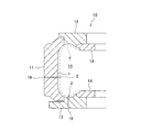
以下、本発明の実施形態について図面を参照しながら説明する。図1は、タイヤ子午線断面に沿ったタイヤ加硫金型10の断面を示しており、図2,3は、その要部を拡大して示している。
Hereinafter, embodiments of the present invention will be described with reference to the drawings. FIG. 1 shows a cross section of a
図1に示すように、タイヤ加硫金型10は、キャビティ15にセットされたタイヤTの外表面に接する成形面1を備える。成形面1には、加硫成形時にタイヤと成形面1との間の余分な空気を排出するために、金型10の内部(キャビティ15)と外部とを連通させる多数の排気孔16が設けられている。図2に拡大して示すように、その成形面1で開口する排気孔16にベントプラグ2が装着されている。ベントプラグ2は、いわゆるスプリングベントとして構成されている。
As shown in FIG. 1, the
成形面1の素材としては、アルミニウム材が例示される。このアルミニウム材は、純アルミ系の素材のみならずアルミニウム合金を含む概念であり、例えばAl−Cu系、Al−Mg系、Al−Mg−Si系、Al−Zn−Mg系、Al−Mn系、Al−Si系が挙げられる。後述するハウジング3とステム4は、それぞれステンレスやS45Cに代表される鋼材からなることが好ましく、これらは同種金属でもよいが異種金属でも構わない。
An example of the material for the
本実施形態の金型10は、タイヤのトレッド部を成形するトレッド型部11と、タイヤのサイドウォール部を成形するサイド型部12,13と、タイヤのビード部が嵌合されるビードリング14とを備える。図示を省略しているが、トレッド型部11の内面には、タイヤのトレッド面に溝を形成するための凸状の骨部が設けられている。図1では、トレッド型部11の内面で開口する1つの排気孔16と、サイド型部13の内面で開口する1つの排気孔16を描いているが、実際には、トレッド型部11やサイド型部12,13の内面で開口する多数の排気孔16が設けられている。
The
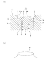
図2に示すように、ベントプラグ2は、排気路21を内部に有する筒状のハウジング3と、ハウジング3に挿入され、排気路21を開閉する弁体となるステム4と、排気路21を開放するようにステム4をキャビティ15に向けて付勢する付勢部材としてのスプリング5とを備える。ハウジング3は、円孔である排気孔16に嵌入され、成形面1に対して固定されている。ハウジング3の開口部31は、キャビティ15に面した頂面31aを有する。ハウジング3の下端部32には、貫通孔32aと内鍔状の支持部32bとが形成されている。
As shown in FIG. 2, the
ステム4は、ハウジング3の軸方向に延びる柱状の胴部41と、ハウジング3の開口部31の内面31bに接することにより排気路21を閉鎖する頭部42とを有する。胴部41は、スプリング5に挿入されており、その下端には貫通孔32aより大径のストッパー43が設けられている。ストッパー43は、スリット44を閉じるように弾性変形させることで、貫通孔32aを通過できる。頭部42は、胴部41の上端に一体的に連結されている。頭部42には、キャビティ15に面する頂面42aと、開口部31の内面31bに対向する側面42bとが形成されている。
The stem 4 has a
スプリング5は、胴部41を取り囲むようにして配置され、頭部42と支持部32bとの間に介在してステム4を付勢する。本実施形態では、付勢部材としてコイル状のスプリングを用いているが、これに限定されるものではなく、例えば皿バネや板バネなどを利用しても構わない。
The
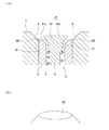
図2に示したベントプラグ2は、排気路21が開放される状態(以下、「開状態」と呼ぶ)にある。ベントプラグ2が開状態にある間は、タイヤの外表面が成形面1に接近する動作に伴って、キャビティ15内の空気が排気路21を介して金型10の外部へ排出される。タイヤの外表面がステム4を押し下げると、図3のように頭部42がハウジング3の開口部31の内面31bに接して排気路21が閉鎖される。図3に示したベントプラグ2は、排気路21が閉鎖される状態(以下、「閉状態」と呼ぶ)にある。
The
図2,3のように、ハウジング3の開口部31の頂面31aと、ステム4の頭部42の頂面42aは、それぞれ平面により形成されている。また、ハウジング3の開口部31の頂面31aと、排気路21が閉鎖される状態におけるステム4の頭部42の頂面42aとが、いずれも成形面1よりも反キャビティ側(図2,3の下側)に配置されている。このため、側方から流れてきた未加硫ゴムが、側方からではなくキャビティ15側(図2,3の上側)から頭部42に接触しやすくなり、流入ゴムを減らしてゴム噛みの発生を抑制できる。しかも、タイヤの外表面に形成される突起が目立たない形状となるので、外観品質の確保に資する。
As shown in FIGS. 2 and 3, the
また、上記のように、頂面31aと、閉状態における頂面42aとが、成形面1よりも反キャビティ側に配置されているので、タイヤの外表面が成形面1に接する段階では、まだステム4を押し下げる余地が残される。即ち、成形面1に接したタイヤの外表面が更に反キャビティ側に押し込まれることにより、ステム4が完全に押し下げられて閉状態となる。それ故、従来のタイヤ加硫金型に比べて空気を排出する効果が長く得られ、残留空気を低減できることにより、タイヤの外観品質の向上に資する。
In addition, as described above, the
ハウジング3の埋設深さDは、成形面1の法線方向(図3の上下方向)に沿って、成形面1からハウジング3の開口部31の頂面31aまでの距離として測定される。埋設深さDは、例えば0.1mm以上に設定されるが、ゴム噛みの抑制効果を高めるうえで0.3mm以上にすることが好ましい。また、突起がタイヤの外観に違和感を与えないようにするため、埋設深さDは1mm以下であることが好ましい。突起の根元を起点としたクラックの発生を抑えるうえでは、埋設深さDを0.8mm以下にすることが好ましく、0.6mm以下にすることがより好ましい。
The embedding depth D of the
本実施形態では、図3のように、排気路21が閉鎖される状態におけるステム4の頭部42の頂面42aが、ハウジング3の開口部31の頂面31aと面一に配置される。即ち、閉状態では、頂面42aと頂面31aとが同一平面上に配置される。また、閉状態では、ステム4の頭部42とハウジング3の開口部31とがテーパ状の接触領域を形成し、その接触領域の外縁6が開口部31の頂面31a上に設定される。かかる構成によれば、タイヤの外表面に形成される突起の頂面に段差や筋が形成されないので、タイヤの外観品質をより良好に確保できる。
In the present embodiment, as shown in FIG. 3, the
本実施形態では、図2のように、排気路21が開放される状態におけるステム4の頭部42の頂面42aが、成形面1よりも反キャビティ側に配置されている。これにより、側方から流れてきた未加硫ゴムが、頭部42に横当たりすることなく、より確実にキャビティ15側からステム4の頭部42に接触するようになり、ゴム噛みの発生を効果的に抑制できる。開状態での頂面42aが成形面1と面一に配置されることでも同様の効果が得られるが、上記のような反キャビティ側への配置の方がゴム噛みの抑制効果に優れる。
In the present embodiment, as shown in FIG. 2, the
この金型10では、開口部31の頂面31aと、閉状態における頭部42の頂面42aとが成形面1よりも反キャビティ側に配置されるため、成形面1には図3に描いているような窪みが形成される。加硫成形後のタイヤの外表面には、その窪みに充填されたゴムによって突起が形成されるものの、突起は比較的目立たない形状となるため、タイヤの外観品質は確保される。
In this
しかし、ゴムの配合によっても左右されるが、走行時の変形が繰り返し作用することにより突起に応力が集中すると、その突起の根元を起点とした微細なクラックが発生し、それに起因してタイヤの外観品質が損なわれる場合がある。特に、サイドウォール面のようなタイヤの非接地面に形成された突起は、走行に伴って消失するものではないため、クラックの発生が懸念される。かかる事情により、本発明のタイヤ加硫金型では、突起の根元を起点としたクラックの発生を予防しうる構成を備えることが望ましい。 However, although it depends on the rubber composition, when stress is concentrated on the protrusion due to repeated deformation during running, fine cracks originating from the root of the protrusion occur, resulting in the tire Appearance quality may be impaired. In particular, since the protrusion formed on the non-ground surface of the tire such as the sidewall surface does not disappear with traveling, there is a concern about the occurrence of cracks. Under such circumstances, the tire vulcanization mold according to the present invention preferably has a configuration capable of preventing the occurrence of cracks starting from the roots of the protrusions.
図4(a)は、排気孔16の内周面と成形面1とを連ねるエッジ部が湾曲面7により形成されている例を示す。湾曲面7は、排気孔16の内周面と成形面1の双方に対して滑らかに連なっている。湾曲面7の曲率半径rは、例えば0.2〜1.0mm(R0.2〜R1.0)である。かかる構成によれば、図4(b)のように根元が湾曲した形状の突起70がタイヤの外表面に形成され、その突起70の根元に対する応力集中が緩和されることから、クラックの発生を予防してタイヤの外観品質の悪化を防ぐことができる。
FIG. 4A shows an example in which the edge portion connecting the inner peripheral surface of the
この場合、ハウジング3の開口部31の頂面31aは、排気孔16の内周面と湾曲面7との境界7Bと一致しているか、または境界7Bよりも反キャビティ側に配置されていることが好ましく、どちらかと言えば前者の方が望ましい。これにより、タイヤの外表面に形成される突起の側面が滑らかになって目立たない形状となるため、タイヤの外観品質を確保するうえで有益である。図4(a)は、頂面31aが境界7Bと一致している例を示す。境界7Bは、排気孔16の径寸法が変化しない部分と変化する部分との境界でもある。
In this case, the
図5(a)は、排気孔16の内周面と成形面1とを連ねるエッジ部が傾斜面8により形成されている例を示す。傾斜面8は、排気孔16の内周面と成形面1の双方に対して傾斜している。傾斜面8は、例えばC0.2〜C1.0のC面取りに相当する大きさで形成される。かかる構成によれば、図5(b)のように根元が傾斜した形状の突起80がタイヤの外表面に形成され、その突起80の根元に対する応力集中が緩和されることから、クラックの発生を予防してタイヤの外観品質の悪化を防ぐことができる。
FIG. 5A shows an example in which an edge portion connecting the inner peripheral surface of the
この場合も、ハウジング3の開口部31の頂面31aは、排気孔16の内周面と傾斜面8との境界8Bと一致しているか、または境界8Bよりも反キャビティ側に配置されていることが好ましく、どちらかと言えば前者の方が望ましい。これにより、タイヤの外表面に形成される突起の側面が滑らかになって目立たない形状となるため、タイヤの外観品質を確保するうえで有益である。図5(a)は、頂面31aが境界8Bと一致している例を示す。境界8Bは、排気孔16の径寸法が変化しない部分と変化する部分との境界でもある。
Also in this case, the
この金型10を用いたタイヤの製造方法は、金型10のキャビティ15に未加硫タイヤをセットし、その未加硫タイヤに加熱加圧を施して加硫を行う工程を含む。タイヤは、ブラダーと呼ばれるゴムバッグの膨張によって拡張変形し、その外表面が成形面1に押し当たる。その過程で、タイヤと成形面1との間の空気が、ベントプラグ2の排気路21を通じて外部に排出される。このとき、排気孔16内の空間を吸引機により吸引し、排気性能を高めてもよい。
The method of manufacturing a tire using the
上述したタイヤ加硫金型は、ベントプラグの周辺構造を上記の如く構成したこと以外は、通常のタイヤ加硫金型と同等であり、従来公知の形状や材質、機構などが何れも本発明に採用することができる。 The tire vulcanization mold described above is the same as an ordinary tire vulcanization mold except that the peripheral structure of the vent plug is configured as described above, and all of the conventionally known shapes, materials, mechanisms, etc. Can be adopted.
本発明は上述した実施形態に何ら限定されるものではなく、本発明の趣旨を逸脱しない範囲内で種々の改良変更が可能である。前述の実施形態では、トレッド型部と一対のサイド型部とを備えた金型構造であったが、本発明は、これに限定されず、例えばトレッド型部の中央部で上下に二分割された金型構造にも適用できる。 The present invention is not limited to the embodiment described above, and various improvements and modifications can be made without departing from the spirit of the present invention. In the above-described embodiment, the mold structure is provided with a tread mold part and a pair of side mold parts, but the present invention is not limited to this. For example, the mold structure is vertically divided into two at the center part of the tread mold part. Also applicable to mold structures.
本発明の構成と効果を具体的に示すために、タイヤの加硫成形を実施してベア、クラック及び表面凹凸の発生状況を確認した。 In order to specifically show the configuration and effects of the present invention, vulcanization molding of tires was performed to confirm the occurrence of bares, cracks and surface irregularities.
ベアの発生状況
複数のパネラーによる官能評価に基づき、加硫成形後のタイヤの外表面にベアと呼ばれるゴム欠損が確認されて外観品質が許容レベルにない場合を「×」、若干のベアが確認されて外観品質が許容レベルにある場合を「△」、ベアが確認されず外観品質に問題がない場合を「○」と評価した。ゴム噛みによりベントプラグが作動不良を起こした場合は、残留空気によってベアが形成されるため、このベアの発生状況はゴム噛みの抑制効果の指標となり得る。
Bare generation status Based on sensory evaluation by multiple panelists, “X” indicates that there is a rubber deficiency called bare on the outer surface of the tire after vulcanization molding, and the appearance quality is not at an acceptable level. The case where the appearance quality was at an acceptable level was evaluated as “△”, and the case where no bear was confirmed and there was no problem in the appearance quality was evaluated as “◯”. When the vent plug malfunctions due to rubber biting, a bear is formed by residual air, and the occurrence of this bear can be an indicator of the rubber biting suppression effect.
クラックの発生状況
加硫成形後のタイヤに規格荷重及び規格空気圧を負荷し、オゾン濃度0.03ppmの下、ドラム上で30000kmを走行させる台上試験を行った。この試験後のタイヤにおいて、タイヤの外表面に形成された突起の根元に微細なクラックが発生している場合を「×」、微細なクラックの兆候となる皺の発生が確認された場合を「△」、微細なクラックも皺も確認されない場合を「○」と評価した。
Occurrence of cracks A standard test and standard air pressure were applied to the tire after vulcanization molding, and a bench test was carried out by running 30000 km on a drum under an ozone concentration of 0.03 ppm. In the tire after this test, the case where a fine crack is generated at the base of the protrusion formed on the outer surface of the tire is `` x '', and the case where the occurrence of wrinkles that is a sign of a fine crack is confirmed `` “△”, a case where neither fine cracks nor wrinkles were confirmed was evaluated as “◯”.
表面凹凸の状況
10人のパネラーによる官能評価に基づき、加硫成形後のタイヤの外表面の凹凸(突起に起因した凹凸)に明確な違和感がある場合を「×」、指摘されたならば違和感がある場合を「△」、凹凸が気にならない場合を「○」と評価した。
Surface irregularities Based on sensory evaluation by 10 panelists, “x” indicates that the irregularities on the outer surface of the tire after vulcanization (irregularities due to protrusions) are clearly uncomfortable, and if indicated, it is uncomfortable. The case where there was “△” was evaluated, and the case where the unevenness was not concerned was evaluated as “◯”.
表1に示した仕様を除いて各例の構成は共通であり、何れの例でも図2のように閉状態でのステムの頭部の頂面がハウジングの開口部の頂面と面一に配置されるスプリングベントを使用した。また、実施例1〜4では、それぞれ、開状態におけるステムの頭部の頂面が成形面よりも反キャビティ側に配置される構成とした。評価結果を表1に示す。 Except for the specifications shown in Table 1, the configuration of each example is the same. In any example, the top surface of the stem head in the closed state is flush with the top surface of the opening of the housing as shown in FIG. Used spring vents to be placed. Moreover, in Examples 1-4, it was set as the structure by which the top surface of the head part of the stem in an open state is arrange | positioned on the anti-cavity side rather than a molding surface. The evaluation results are shown in Table 1.
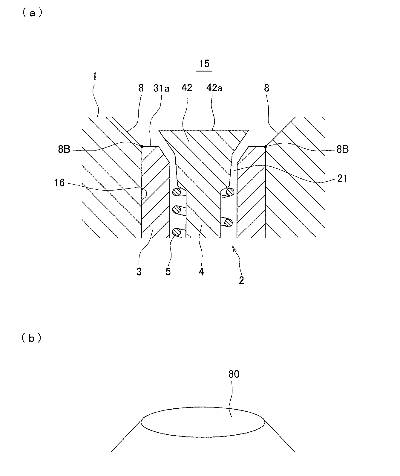
表1に示すように、実施例1〜4では、比較例1,2に比べてベアの発生が低減されており、ゴム噛みの発生が抑制されたものと評価できる。また、実施例1では、突起の根元に微細なクラックが確認されたが、エッジ部の形状を工夫した実施例2〜4ではそれが改善されている。 As shown in Table 1, in Examples 1 to 4, the generation of bears is reduced as compared with Comparative Examples 1 and 2, and it can be evaluated that the occurrence of rubber biting is suppressed. Moreover, in Example 1, although the fine crack was confirmed at the base of protrusion, it is improved in Examples 2-4 which devised the shape of an edge part.
1 成形面
2 ベントプラグ
3 ハウジング
4 ステム
5 スプリング(付勢部材の一例)
7 湾曲面
8 傾斜面
10 タイヤ加硫金型
15 キャビティ
16 排気孔
21 排気路
31 開口部
41 胴部
42 頭部
1 Forming
7
Claims (6)
前記ベントプラグが、排気路を内部に有する筒状のハウジングと、前記ハウジングに挿入され、前記排気路を開閉する弁体となるステムと、前記排気路を開放するように前記ステムを前記キャビティに向けて付勢する付勢部材とを備え、
前記ステムが、前記ハウジングの軸方向に延びる柱状の胴部と、前記ハウジングの開口部の内面に接することにより前記排気路を閉鎖する頭部とを有し、
前記ハウジングの開口部の頂面と、前記ステムの頭部の頂面とが、それぞれ平面により形成され、
前記ハウジングの開口部の頂面と、前記排気路が閉鎖される状態における前記ステムの頭部の頂面とが、いずれも前記成形面よりも反キャビティ側に配置されていることを特徴とするタイヤ加硫金型。 In a tire vulcanization mold comprising a molding surface in contact with an outer surface of a tire set in a cavity, and a vent plug attached to an exhaust hole opened in the molding surface,
The vent plug includes a cylindrical housing having an exhaust passage therein, a stem that is inserted into the housing and serves as a valve body that opens and closes the exhaust passage, and the stem is inserted into the cavity so as to open the exhaust passage. A biasing member biasing toward the
The stem has a columnar body extending in the axial direction of the housing, and a head that closes the exhaust passage by contacting an inner surface of the opening of the housing,
The top surface of the opening of the housing and the top surface of the head of the stem are each formed by a plane,
The top surface of the opening of the housing and the top surface of the head of the stem in a state where the exhaust passage is closed are both disposed on the side opposite to the cavity from the molding surface. Tire vulcanization mold.
Priority Applications (3)
| Application Number | Priority Date | Filing Date | Title |
|---|---|---|---|
| JP2015237014A JP6706492B2 (en) | 2015-12-03 | 2015-12-03 | Tire vulcanization mold and method for manufacturing tire |
| US15/351,713 US9873234B2 (en) | 2015-12-03 | 2016-11-15 | Tire curing mold and manufacturing method for tire |
| CN201611030568.3A CN106976186B (en) | 2015-12-03 | 2016-11-16 | The manufacturing method of tyre vulcanized mould and tire |
Applications Claiming Priority (1)
| Application Number | Priority Date | Filing Date | Title |
|---|---|---|---|
| JP2015237014A JP6706492B2 (en) | 2015-12-03 | 2015-12-03 | Tire vulcanization mold and method for manufacturing tire |
Publications (2)
| Publication Number | Publication Date |
|---|---|
| JP2017100406A true JP2017100406A (en) | 2017-06-08 |
| JP6706492B2 JP6706492B2 (en) | 2020-06-10 |
Family
ID=58800231
Family Applications (1)
| Application Number | Title | Priority Date | Filing Date |
|---|---|---|---|
| JP2015237014A Active JP6706492B2 (en) | 2015-12-03 | 2015-12-03 | Tire vulcanization mold and method for manufacturing tire |
Country Status (3)
| Country | Link |
|---|---|
| US (1) | US9873234B2 (en) |
| JP (1) | JP6706492B2 (en) |
| CN (1) | CN106976186B (en) |
Cited By (4)
| Publication number | Priority date | Publication date | Assignee | Title |
|---|---|---|---|---|
| JP2017213858A (en) * | 2016-05-31 | 2017-12-07 | 住友ゴム工業株式会社 | Vulcanizing mold |
| JP2019081261A (en) * | 2017-10-27 | 2019-05-30 | Toyo Tire株式会社 | Tire vulcanizing mold and method for manufacturing tire |
| CN110549522A (en) * | 2018-06-04 | 2019-12-10 | 通伊欧轮胎株式会社 | Tire vulcanization mold, pneumatic tire manufacturing method, and pneumatic tire |
| JP2023048281A (en) * | 2021-09-28 | 2023-04-07 | Toyo Tire株式会社 | Management method of unvulcanized tread rubber |
Families Citing this family (10)
| Publication number | Priority date | Publication date | Assignee | Title |
|---|---|---|---|---|
| JP6646434B2 (en) * | 2015-12-21 | 2020-02-14 | Toyo Tire株式会社 | Tire vulcanization mold |
| KR101689650B1 (en) * | 2016-06-02 | 2016-12-27 | 주식회사 메가산업 | Spring vent of tire vulcanizing mold |
| FI129777B (en) * | 2017-04-12 | 2022-08-31 | Wd Racing Oy | Valve insert and air venting valve |
| DE102018207743A1 (en) * | 2018-05-17 | 2019-11-21 | Continental Reifen Deutschland Gmbh | Venting unit for a vulcanization mold of a pneumatic vehicle tire and vulcanization mold |
| JP7083700B2 (en) * | 2018-05-31 | 2022-06-13 | Toyo Tire株式会社 | Manufacturing method of tire vulcanization mold and pneumatic tire |
| JP2020001336A (en) * | 2018-06-29 | 2020-01-09 | Toyo Tire株式会社 | Vent sleeve for tire vulcanizing mold and tire vulcanizing mold |
| JP2020066212A (en) * | 2018-10-26 | 2020-04-30 | Toyo Tire株式会社 | Vent plug, tire vulcanizing mold, and tire manufacturing method |
| CZ2018732A3 (en) * | 2018-12-21 | 2020-06-24 | GOTTSCHOL ALCUILUX CZ, spol. s r. o. | Venting valve for venting vulcanizing mould holes |
| CN110027138B (en) * | 2019-06-12 | 2019-12-13 | 山东豪迈机械科技股份有限公司 | Exhaust device and tire mold |
| CN118372499B (en) * | 2024-06-26 | 2024-08-27 | 软控联合科技有限公司 | Two half mould of loose tire |
Citations (9)
| Publication number | Priority date | Publication date | Assignee | Title |
|---|---|---|---|---|
| JPS56127439A (en) * | 1980-03-11 | 1981-10-06 | Yokohama Rubber Co Ltd:The | Molding die for rubber product |
| JP2001205638A (en) * | 2000-01-26 | 2001-07-31 | Sumitomo Rubber Ind Ltd | Vent hole on-off valve and molding die provided with the same |
| JP2004291615A (en) * | 2003-03-11 | 2004-10-21 | Goda Tekkosho:Kk | Mold air release structure |
| US20090095406A1 (en) * | 2004-12-28 | 2009-04-16 | Stefano Cazzanti | Method and Apparatus for Manufacturing Tyres for Vehicle Wheels |
| JP2012240233A (en) * | 2011-05-16 | 2012-12-10 | Bridgestone Corp | Pneumatic tire |
| JP2013252713A (en) * | 2013-08-08 | 2013-12-19 | Toyo Tire & Rubber Co Ltd | Tire mold, method of manufacturing pneumatic tire, and pneumatic tire |
| JP2014210356A (en) * | 2013-04-17 | 2014-11-13 | 東洋ゴム工業株式会社 | Metal mold for vulcanizing tire, and vent plug to be used in the mold |
| JP2015009544A (en) * | 2013-07-02 | 2015-01-19 | 東洋ゴム工業株式会社 | Tire vulcanizing mold and method for manufacturing tire |
| JP2015016609A (en) * | 2013-07-10 | 2015-01-29 | 東洋ゴム工業株式会社 | Tire vulcanizing mold and tire manufacturing method |
Family Cites Families (10)
| Publication number | Priority date | Publication date | Assignee | Title |
|---|---|---|---|---|
| GB922788A (en) | 1958-08-25 | 1963-04-03 | Dunlop Rubber Co | Venting means for moulds |
| US4492554A (en) * | 1980-08-26 | 1985-01-08 | Corn States Metal Fabricators, Inc. | Valve unit for a mold vent |
| US4351789A (en) * | 1981-07-27 | 1982-09-28 | The B. F. Goodrich Company | Mold and process for molding |
| JP3717895B2 (en) * | 2002-07-04 | 2005-11-16 | 韓国タイヤ株式会社 | Tire vulcanization mold vent device |
| CN100548607C (en) * | 2005-01-28 | 2009-10-14 | 有限会社T&K | Exhaust component and mold equipped with the above-mentioned exhaust component |
| JP4959255B2 (en) * | 2006-08-22 | 2012-06-20 | 東洋ゴム工業株式会社 | Pneumatic tire and manufacturing method thereof |
| JP5356447B2 (en) * | 2011-04-05 | 2013-12-04 | 東洋ゴム工業株式会社 | Tire mold, method for producing pneumatic tire, and pneumatic tire |
| JP6087237B2 (en) | 2013-07-24 | 2017-03-01 | 東洋ゴム工業株式会社 | Manufacturing method of tire vulcanizing mold |
| JP2015051611A (en) | 2013-09-09 | 2015-03-19 | 東洋ゴム工業株式会社 | Tire vulcanization mold and tire manufacturing method |
| WO2015156413A1 (en) * | 2014-04-11 | 2015-10-15 | 株式会社ブリヂストン | Mold for rubber article, method for producing tire, and tire |
-
2015
- 2015-12-03 JP JP2015237014A patent/JP6706492B2/en active Active
-
2016
- 2016-11-15 US US15/351,713 patent/US9873234B2/en active Active
- 2016-11-16 CN CN201611030568.3A patent/CN106976186B/en active Active
Patent Citations (9)
| Publication number | Priority date | Publication date | Assignee | Title |
|---|---|---|---|---|
| JPS56127439A (en) * | 1980-03-11 | 1981-10-06 | Yokohama Rubber Co Ltd:The | Molding die for rubber product |
| JP2001205638A (en) * | 2000-01-26 | 2001-07-31 | Sumitomo Rubber Ind Ltd | Vent hole on-off valve and molding die provided with the same |
| JP2004291615A (en) * | 2003-03-11 | 2004-10-21 | Goda Tekkosho:Kk | Mold air release structure |
| US20090095406A1 (en) * | 2004-12-28 | 2009-04-16 | Stefano Cazzanti | Method and Apparatus for Manufacturing Tyres for Vehicle Wheels |
| JP2012240233A (en) * | 2011-05-16 | 2012-12-10 | Bridgestone Corp | Pneumatic tire |
| JP2014210356A (en) * | 2013-04-17 | 2014-11-13 | 東洋ゴム工業株式会社 | Metal mold for vulcanizing tire, and vent plug to be used in the mold |
| JP2015009544A (en) * | 2013-07-02 | 2015-01-19 | 東洋ゴム工業株式会社 | Tire vulcanizing mold and method for manufacturing tire |
| JP2015016609A (en) * | 2013-07-10 | 2015-01-29 | 東洋ゴム工業株式会社 | Tire vulcanizing mold and tire manufacturing method |
| JP2013252713A (en) * | 2013-08-08 | 2013-12-19 | Toyo Tire & Rubber Co Ltd | Tire mold, method of manufacturing pneumatic tire, and pneumatic tire |
Cited By (5)
| Publication number | Priority date | Publication date | Assignee | Title |
|---|---|---|---|---|
| JP2017213858A (en) * | 2016-05-31 | 2017-12-07 | 住友ゴム工業株式会社 | Vulcanizing mold |
| JP2019081261A (en) * | 2017-10-27 | 2019-05-30 | Toyo Tire株式会社 | Tire vulcanizing mold and method for manufacturing tire |
| CN110549522A (en) * | 2018-06-04 | 2019-12-10 | 通伊欧轮胎株式会社 | Tire vulcanization mold, pneumatic tire manufacturing method, and pneumatic tire |
| JP2023048281A (en) * | 2021-09-28 | 2023-04-07 | Toyo Tire株式会社 | Management method of unvulcanized tread rubber |
| JP7716295B2 (en) | 2021-09-28 | 2025-07-31 | Toyo Tire株式会社 | Management method for unvulcanized tread rubber |
Also Published As
| Publication number | Publication date |
|---|---|
| CN106976186A (en) | 2017-07-25 |
| US20170157871A1 (en) | 2017-06-08 |
| CN106976186B (en) | 2019-03-01 |
| JP6706492B2 (en) | 2020-06-10 |
| US9873234B2 (en) | 2018-01-23 |
Similar Documents
| Publication | Publication Date | Title |
|---|---|---|
| JP6706492B2 (en) | Tire vulcanization mold and method for manufacturing tire | |
| JP3391756B2 (en) | Pneumatic tire | |
| US10029433B1 (en) | Tire vulcanization mold and tire manufacturing method using the same | |
| JP6898828B2 (en) | Tire vulcanization mold and tire manufacturing method | |
| CN106891457B (en) | Tire Vulcanization Mould | |
| JP2008265502A (en) | Pneumatic tire | |
| CN203765842U (en) | Tire vulcanizing metal die | |
| JP2018103517A (en) | Tire vulcanization mold and pneumatic tire | |
| JP6088921B2 (en) | Tire vulcanization mold and tire manufacturing method | |
| CN203805188U (en) | Tire vulcanization metal mold | |
| JP2006159596A (en) | Tire molding die, tire molding die plug, and tire manufactured using this tire molding die | |
| JP6059103B2 (en) | Tire vulcanization mold and tire manufacturing method | |
| JP6087089B2 (en) | Vent piece for tire vulcanization mold, tire vulcanization mold and tire manufacturing method | |
| JP6309325B2 (en) | Mold and pneumatic tire manufacturing method | |
| JP6133159B2 (en) | Tire vulcanization mold | |
| US11059247B2 (en) | Vent plug, tire cure mold, and method of manufacturing tire | |
| JP2005028589A (en) | Tire molding die, plug used for vent hole of tire molding die, and tire manufactured using this tire molding die | |
| JP2020066212A (en) | Vent plug, tire vulcanizing mold, and tire manufacturing method | |
| JP2019209488A (en) | Tire vulcanizing mold and method for manufacturing pneumatic tire | |
| JP2006168191A (en) | Tire molding die, tire molding die plug, and tire manufactured using this tire molding die | |
| JP4501651B2 (en) | Tire mold and tire mold plug | |
| JP2005161717A (en) | Tire molding die, plug used for vent hole of tire molding die, and tire manufactured using this tire molding die | |
| JP6629585B2 (en) | Tire vulcanization mold | |
| JP2020066210A (en) | Vent plug, tire vulcanizing mold and method for manufacturing tire | |
| JP2006110954A (en) | Tire molding die, plug used for vent hole of tire molding die, and tire manufactured using this tire molding die |
Legal Events
| Date | Code | Title | Description |
|---|---|---|---|
| A621 | Written request for application examination |
Free format text: JAPANESE INTERMEDIATE CODE: A621 Effective date: 20181030 |
|
| A977 | Report on retrieval |
Free format text: JAPANESE INTERMEDIATE CODE: A971007 Effective date: 20190909 |
|
| A131 | Notification of reasons for refusal |
Free format text: JAPANESE INTERMEDIATE CODE: A131 Effective date: 20191113 |
|
| A521 | Request for written amendment filed |
Free format text: JAPANESE INTERMEDIATE CODE: A523 Effective date: 20191225 |
|
| TRDD | Decision of grant or rejection written | ||
| A01 | Written decision to grant a patent or to grant a registration (utility model) |
Free format text: JAPANESE INTERMEDIATE CODE: A01 Effective date: 20200428 |
|
| A61 | First payment of annual fees (during grant procedure) |
Free format text: JAPANESE INTERMEDIATE CODE: A61 Effective date: 20200518 |
|
| R150 | Certificate of patent or registration of utility model |
Ref document number: 6706492 Country of ref document: JP Free format text: JAPANESE INTERMEDIATE CODE: R150 |
|
| R250 | Receipt of annual fees |
Free format text: JAPANESE INTERMEDIATE CODE: R250 |
|
| R250 | Receipt of annual fees |
Free format text: JAPANESE INTERMEDIATE CODE: R250 |
|
| R250 | Receipt of annual fees |
Free format text: JAPANESE INTERMEDIATE CODE: R250 |
|
| R250 | Receipt of annual fees |
Free format text: JAPANESE INTERMEDIATE CODE: R250 |