JP2017100456A - Container with attachment - Google Patents
Container with attachment Download PDFInfo
- Publication number
- JP2017100456A JP2017100456A JP2017017010A JP2017017010A JP2017100456A JP 2017100456 A JP2017100456 A JP 2017100456A JP 2017017010 A JP2017017010 A JP 2017017010A JP 2017017010 A JP2017017010 A JP 2017017010A JP 2017100456 A JP2017100456 A JP 2017100456A
- Authority
- JP
- Japan
- Prior art keywords
- container
- mold
- parison
- molding
- attachment
- Prior art date
- Legal status (The legal status is an assumption and is not a legal conclusion. Google has not performed a legal analysis and makes no representation as to the accuracy of the status listed.)
- Granted
Links
Images





Classifications
-
- B—PERFORMING OPERATIONS; TRANSPORTING
- B29—WORKING OF PLASTICS; WORKING OF SUBSTANCES IN A PLASTIC STATE IN GENERAL
- B29C—SHAPING OR JOINING OF PLASTICS; SHAPING OF MATERIAL IN A PLASTIC STATE, NOT OTHERWISE PROVIDED FOR; AFTER-TREATMENT OF THE SHAPED PRODUCTS, e.g. REPAIRING
- B29C49/00—Blow-moulding, i.e. blowing a preform or parison to a desired shape within a mould; Apparatus therefor
- B29C49/42—Component parts, details or accessories; Auxiliary operations
- B29C49/48—Moulds
- B29C49/4802—Moulds with means for locally compressing part(s) of the parison in the main blowing cavity
-
- B—PERFORMING OPERATIONS; TRANSPORTING
- B29—WORKING OF PLASTICS; WORKING OF SUBSTANCES IN A PLASTIC STATE IN GENERAL
- B29C—SHAPING OR JOINING OF PLASTICS; SHAPING OF MATERIAL IN A PLASTIC STATE, NOT OTHERWISE PROVIDED FOR; AFTER-TREATMENT OF THE SHAPED PRODUCTS, e.g. REPAIRING
- B29C49/00—Blow-moulding, i.e. blowing a preform or parison to a desired shape within a mould; Apparatus therefor
- B29C49/42—Component parts, details or accessories; Auxiliary operations
- B29C49/48—Moulds
- B29C49/4802—Moulds with means for locally compressing part(s) of the parison in the main blowing cavity
- B29C49/4812—Moulds with means for locally compressing part(s) of the parison in the main blowing cavity and welding opposite wall parts of the parisons or preforms to each other
- B29C49/4815—Moulds with means for locally compressing part(s) of the parison in the main blowing cavity and welding opposite wall parts of the parisons or preforms to each other by means of movable mould parts
-
- B—PERFORMING OPERATIONS; TRANSPORTING
- B29—WORKING OF PLASTICS; WORKING OF SUBSTANCES IN A PLASTIC STATE IN GENERAL
- B29C—SHAPING OR JOINING OF PLASTICS; SHAPING OF MATERIAL IN A PLASTIC STATE, NOT OTHERWISE PROVIDED FOR; AFTER-TREATMENT OF THE SHAPED PRODUCTS, e.g. REPAIRING
- B29C49/00—Blow-moulding, i.e. blowing a preform or parison to a desired shape within a mould; Apparatus therefor
- B29C49/42—Component parts, details or accessories; Auxiliary operations
- B29C49/48—Moulds
- B29C49/50—Moulds having cutting or deflashing means
-
- B—PERFORMING OPERATIONS; TRANSPORTING
- B29—WORKING OF PLASTICS; WORKING OF SUBSTANCES IN A PLASTIC STATE IN GENERAL
- B29C—SHAPING OR JOINING OF PLASTICS; SHAPING OF MATERIAL IN A PLASTIC STATE, NOT OTHERWISE PROVIDED FOR; AFTER-TREATMENT OF THE SHAPED PRODUCTS, e.g. REPAIRING
- B29C49/00—Blow-moulding, i.e. blowing a preform or parison to a desired shape within a mould; Apparatus therefor
- B29C49/42—Component parts, details or accessories; Auxiliary operations
- B29C49/48—Moulds
- B29C49/54—Moulds for undercut articles
-
- B—PERFORMING OPERATIONS; TRANSPORTING
- B29—WORKING OF PLASTICS; WORKING OF SUBSTANCES IN A PLASTIC STATE IN GENERAL
- B29C—SHAPING OR JOINING OF PLASTICS; SHAPING OF MATERIAL IN A PLASTIC STATE, NOT OTHERWISE PROVIDED FOR; AFTER-TREATMENT OF THE SHAPED PRODUCTS, e.g. REPAIRING
- B29C49/00—Blow-moulding, i.e. blowing a preform or parison to a desired shape within a mould; Apparatus therefor
- B29C49/42—Component parts, details or accessories; Auxiliary operations
- B29C49/72—Deflashing outside the mould
- B29C49/74—Deflashing the neck portion
-
- B—PERFORMING OPERATIONS; TRANSPORTING
- B29—WORKING OF PLASTICS; WORKING OF SUBSTANCES IN A PLASTIC STATE IN GENERAL
- B29C—SHAPING OR JOINING OF PLASTICS; SHAPING OF MATERIAL IN A PLASTIC STATE, NOT OTHERWISE PROVIDED FOR; AFTER-TREATMENT OF THE SHAPED PRODUCTS, e.g. REPAIRING
- B29C49/00—Blow-moulding, i.e. blowing a preform or parison to a desired shape within a mould; Apparatus therefor
- B29C49/42—Component parts, details or accessories; Auxiliary operations
- B29C49/76—Neck calibration
-
- B—PERFORMING OPERATIONS; TRANSPORTING
- B29—WORKING OF PLASTICS; WORKING OF SUBSTANCES IN A PLASTIC STATE IN GENERAL
- B29C—SHAPING OR JOINING OF PLASTICS; SHAPING OF MATERIAL IN A PLASTIC STATE, NOT OTHERWISE PROVIDED FOR; AFTER-TREATMENT OF THE SHAPED PRODUCTS, e.g. REPAIRING
- B29C49/00—Blow-moulding, i.e. blowing a preform or parison to a desired shape within a mould; Apparatus therefor
- B29C49/42—Component parts, details or accessories; Auxiliary operations
- B29C49/48—Moulds
- B29C49/4802—Moulds with means for locally compressing part(s) of the parison in the main blowing cavity
- B29C2049/4807—Moulds with means for locally compressing part(s) of the parison in the main blowing cavity by movable mould parts in the mould halves
- B29C2049/481—Moulds with means for locally compressing part(s) of the parison in the main blowing cavity by movable mould parts in the mould halves the movable mould parts moving outwardly, e.g. the mould size being increased due to the movement of the movable mould parts
-
- B—PERFORMING OPERATIONS; TRANSPORTING
- B29—WORKING OF PLASTICS; WORKING OF SUBSTANCES IN A PLASTIC STATE IN GENERAL
- B29C—SHAPING OR JOINING OF PLASTICS; SHAPING OF MATERIAL IN A PLASTIC STATE, NOT OTHERWISE PROVIDED FOR; AFTER-TREATMENT OF THE SHAPED PRODUCTS, e.g. REPAIRING
- B29C49/00—Blow-moulding, i.e. blowing a preform or parison to a desired shape within a mould; Apparatus therefor
- B29C49/42—Component parts, details or accessories; Auxiliary operations
- B29C49/48—Moulds
- B29C2049/4879—Moulds characterised by mould configurations
-
- B—PERFORMING OPERATIONS; TRANSPORTING
- B29—WORKING OF PLASTICS; WORKING OF SUBSTANCES IN A PLASTIC STATE IN GENERAL
- B29C—SHAPING OR JOINING OF PLASTICS; SHAPING OF MATERIAL IN A PLASTIC STATE, NOT OTHERWISE PROVIDED FOR; AFTER-TREATMENT OF THE SHAPED PRODUCTS, e.g. REPAIRING
- B29C2793/00—Shaping techniques involving a cutting or machining operation
- B29C2793/0009—Cutting out
- B29C2793/0018—Cutting out for making a hole
-
- B—PERFORMING OPERATIONS; TRANSPORTING
- B29—WORKING OF PLASTICS; WORKING OF SUBSTANCES IN A PLASTIC STATE IN GENERAL
- B29C—SHAPING OR JOINING OF PLASTICS; SHAPING OF MATERIAL IN A PLASTIC STATE, NOT OTHERWISE PROVIDED FOR; AFTER-TREATMENT OF THE SHAPED PRODUCTS, e.g. REPAIRING
- B29C2793/00—Shaping techniques involving a cutting or machining operation
- B29C2793/0045—Perforating
-
- B—PERFORMING OPERATIONS; TRANSPORTING
- B29—WORKING OF PLASTICS; WORKING OF SUBSTANCES IN A PLASTIC STATE IN GENERAL
- B29C—SHAPING OR JOINING OF PLASTICS; SHAPING OF MATERIAL IN A PLASTIC STATE, NOT OTHERWISE PROVIDED FOR; AFTER-TREATMENT OF THE SHAPED PRODUCTS, e.g. REPAIRING
- B29C49/00—Blow-moulding, i.e. blowing a preform or parison to a desired shape within a mould; Apparatus therefor
- B29C49/02—Combined blow-moulding and manufacture of the preform or the parison
- B29C49/04—Extrusion blow-moulding
-
- B—PERFORMING OPERATIONS; TRANSPORTING
- B29—WORKING OF PLASTICS; WORKING OF SUBSTANCES IN A PLASTIC STATE IN GENERAL
- B29C—SHAPING OR JOINING OF PLASTICS; SHAPING OF MATERIAL IN A PLASTIC STATE, NOT OTHERWISE PROVIDED FOR; AFTER-TREATMENT OF THE SHAPED PRODUCTS, e.g. REPAIRING
- B29C49/00—Blow-moulding, i.e. blowing a preform or parison to a desired shape within a mould; Apparatus therefor
- B29C49/22—Blow-moulding, i.e. blowing a preform or parison to a desired shape within a mould; Apparatus therefor using multilayered preforms or parisons
-
- B—PERFORMING OPERATIONS; TRANSPORTING
- B29—WORKING OF PLASTICS; WORKING OF SUBSTANCES IN A PLASTIC STATE IN GENERAL
- B29L—INDEXING SCHEME ASSOCIATED WITH SUBCLASS B29C, RELATING TO PARTICULAR ARTICLES
- B29L2009/00—Layered products
-
- B—PERFORMING OPERATIONS; TRANSPORTING
- B29—WORKING OF PLASTICS; WORKING OF SUBSTANCES IN A PLASTIC STATE IN GENERAL
- B29L—INDEXING SCHEME ASSOCIATED WITH SUBCLASS B29C, RELATING TO PARTICULAR ARTICLES
- B29L2031/00—Other particular articles
- B29L2031/712—Containers; Packaging elements or accessories, Packages
-
- B—PERFORMING OPERATIONS; TRANSPORTING
- B29—WORKING OF PLASTICS; WORKING OF SUBSTANCES IN A PLASTIC STATE IN GENERAL
- B29L—INDEXING SCHEME ASSOCIATED WITH SUBCLASS B29C, RELATING TO PARTICULAR ARTICLES
- B29L2031/00—Other particular articles
- B29L2031/712—Containers; Packaging elements or accessories, Packages
- B29L2031/7172—Fuel tanks, jerry cans
Landscapes
- Engineering & Computer Science (AREA)
- Manufacturing & Machinery (AREA)
- Mechanical Engineering (AREA)
- Blow-Moulding Or Thermoforming Of Plastics Or The Like (AREA)
- Moulds For Moulding Plastics Or The Like (AREA)
Abstract
【課題】ブロー成形時に、容器、例えば、車両用燃料タンクの取付部付燃料給油口を成形する方法と装置を提供する。【解決手段】取付部36を備えた容器12を成形する方法は、成形面と、前記成形面の一部を画定する凹型領域24と、分割するために互いに開くと共に密閉するために互いに閉じる金型部14と、を有する金型、を設ける工程を有する。金型が開いた時に、溶融プラスチックパリソン16が金型に提供され、その後、金型が閉じられる。そして、パリソンの一部が凹型領域に入るように、パリソンが成形面に対して膨張する。凹型領域内に設けられたパリソンの一部は、取付部を画定するために、前記金型およびパリソンに関連して二次成形装置40を動かすことによって成形される。【選択図】図1A method and an apparatus for molding a container, for example, a fuel filler port with a mounting portion of a fuel tank for a vehicle at the time of blow molding. A method of molding a container (12) with a mounting portion (36) includes a molding surface, a concave region (24) defining a part of the molding surface, and a gold that closes each other to open and seal to each other. And a step of providing a mold having the mold part 14. When the mold is opened, the molten plastic parison 16 is provided to the mold and then the mold is closed. Then, the parison expands with respect to the molding surface so that a part of the parison enters the concave region. A portion of the parison provided in the recessed area is molded by moving the secondary molding device 40 relative to the mold and parison to define the attachment. [Selection] Figure 1
Description
本発明は、一般的な容器製造に関する。 The present invention relates to general container manufacturing.
容器は、その内部に設けられる構成部品、または、その外部に接続される構成部品、を有することがある。例えば、車両用燃料タンクは、通常、その燃料タンクと接続され、燃料をタンクに入れるための燃料給油口を有する。また、容器は、燃料タンクに設けられるキャリアまたは他の支持物に搭載される構成部品を有する。その構成部品は、締め具や溶接等で、すでに成形された燃料タンクの壁に固定されたフランジに取り付けられる。 The container may have a component provided inside thereof or a component connected to the outside thereof. For example, a vehicle fuel tank is usually connected to the fuel tank and has a fuel filler opening for putting fuel into the tank. The container also has components that are mounted on a carrier or other support provided in the fuel tank. The components are attached to a flange fixed to the already formed fuel tank wall by fasteners, welding or the like.
本発明の容器を成形する方法は、成形面と、前記成形面の一部を画定する凹型領域と、分割するために互いに開くと共に密閉するために互いに閉じる金型部と、を有する金型、を設ける工程と、前記金型が開いた時に、前記金型に溶融プラスチックパリソンを提供する工程と、前記金型を閉じる工程と、前記パリソンの一部が前記凹型領域に入るように、前記成形面に対してパリソンを膨らませる工程と、取付部を画定するために、前記金型に関連して二次成形装置を動かすことにより、前記凹型領域内で前記パリソンの一部を成形する工程と、を有する。 A method for molding a container according to the present invention comprises a mold having a molding surface, a concave region defining a part of the molding surface, and mold parts that open to each other for division and close to each other for sealing. Providing the molten plastic parison to the mold when the mold is opened; closing the mold; and forming the parison so that a portion of the parison enters the concave mold region. Inflating the parison relative to the surface; and forming a portion of the parison within the recessed area by moving a secondary molding device relative to the mold to define a mounting portion; Have.
また、本発明の容器を成形する他の方法は、成形面と、前記成形面の一部を画定する通路と、前記成形面の一部を画定すると共に前記通路に開口するカウンタボアと、分割するために互いに開くと共に密閉するために互いに閉じる金型部と、を有する金型、を設ける工程と、前記金型が開いた時に、前記金型に溶融プラスチックパリソンを提供する工程と、前記金型を閉じる工程と、前記パリソンが前記通路および前記カウンタボアに入るように、前記成形面に対して前記パリソンを膨らませる工程と、二次成形装置の本体と前記金型との間に設けられる取付部を画定するために、前記金型に関連して前記本体を前記カウンタボアに隣接するパリソンの一部まで動かすことにより、前記通路内に前記パリソンの一部を挿入すると共に前記容器の成形面を画定する工程と、を有する。 Another method of molding the container of the present invention includes a molding surface, a passage defining a part of the molding surface, a counterbore defining a part of the molding surface and opening into the passage, and a division. Providing molds having mold parts that are open to each other and closed to be sealed, providing a molten plastic parison to the mold when the mold is opened, and A step of closing the mold, a step of inflating the parison with respect to the molding surface so that the parison enters the passage and the counterbore, and provided between the main body of the secondary molding apparatus and the mold Inserting a portion of the parison into the passage and moving the body relative to the mold to a portion of the parison adjacent the counterbore to define a mounting portion And a step of defining a molding surface.
本発明の好ましい実施例については、明細書に添付した図面に基づいて詳細に説明する。 Preferred embodiments of the present invention will be described in detail with reference to the drawings attached to the specification.
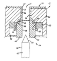
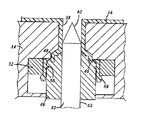
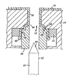
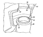
図面をさらに詳細に参照すると、図1〜8は、装置10を説明するための図であり、また、図9は、プラスチック容器12を成形する方法を説明するための図である。容器12は、中空内部を有し、ブロー成形などで成形される。そのようなブロー成形プロセスでは、プラスチック製の溶融パリソン16が、1つ以上の金型部14を有する金型に位置付けられる。金型部14は、容器12の所望の外部形状を成形するために、キャビティを画定する。金型を開いてパリソン16をキャビティに収容するために、一方の金型部14は、他方の金型部14に対して相対的に動く。また、金型部14は、実質的に完全に金型を密閉するために閉じられる。金型部14が閉じられると、空気のような流体は、圧力を受けて、パリソン16の内部に圧力をかける。このため、パリソンは、膨張して金型のキャビティに接合される。
Referring to the drawings in more detail, FIGS. 1 to 8 are views for explaining the
最終的に冷却して成形する前に、容器の内部にアクセスできるように、成形プロセス中、パリソン材料が切断されたり、分割されたり、引き裂かれたりする。部分的に成形された容器12の内部を露出させるために、分離された金型部14、すなわち、開かれた金型部14では、さまざまな装置を容器の内部に挿入することができる。そして、金型部14は、その容器の一部を再結合するために閉じられる。その後、少なくともこの実施形態では、液体を収容する実質的に完全な密閉箱を画定するために、パリソン材料が冷却されて、容器が成形される。液体として、例えば、自動車などに用いられ内燃エンジンを駆動する燃料などがあるが、それに限定されない。
During the molding process, the parison material is cut, split or torn so that the interior of the container can be accessed prior to final cooling and molding. In order to expose the interior of the partially molded
容器12を成形するために用いられるパリソン16は、異なる材料で作られた多層を有することができる。その多層は、同時に押出されることができ、必要に応じて、容器と異なる性質や特性を有することができる。自動車用燃料タンクを例に挙げると、容器12またはタンクは、例えば高密度ポリエチレン(HDPE)から成る1つ以上の構造層、エチレンビニルアルコール(EVOH)から成る蒸気バリア層、1つ以上の接着剤層、から構成される。接着剤層は、構造層および蒸気バリア層を一緒に接合することを容易にする。一般的な容器成形プロセス、および、そのプロセスで成形される典型的な容器は、2009年6月25日に提出された米国特許出願第12/491,964号に開示されている。完全に参照することにより、その明細書の開示された内容は、本明細書に組み込まれる。
The
さらに詳細に説明すると、図1〜5は、容器12を成形するための金型装置の一部と二次成形装置20とを示す図である。金型装置は、1つ以上の金型部14と、開口部22と、を備えている。金型部14は、2つ設けられていたり、分割されていたりする。また、金型部14は、内部成形面で画定されるキャビティを有する。内部成形面は、容器を成形する材料の外側と接合されるように、構成されている。開口部22は、凹型領域24に延びている、または、凹型領域24の一部で画定されている。凹型領域24は、通路26を画定する。また、凹型領域24は、通路26に連通する第1カウンタボア28と、第1カウンタボア28に連なる第2カウンタボア30と、を有する。インサート32は、第2カウンタボア30内に配置されている。インサート32は、環状であり、少なくとも第2カウンタボア30の一部を画定する。インサート32の下側には、段差(step)34が設けられている。具体的には、段差34は、インサート32の下側で成形面からさらに間隔を置いて配置されている。この実施形態では、パリソン16の材料は、図1に示すように、通路26に押し込まれて、通路26の内面と、第1、第2カウンタボア28、30の内面に接する。開口部33は、二次成形装置の少なくとも一部が金型部14に出し入れできるように、金型部14に設けられている。
More specifically, FIGS. 1 to 5 are views showing a part of a mold apparatus and a
図6〜8に示すように、通路26と、第1、第2カウンタボア28、30を有する凹型領域24は、パリソン16において、すなわち、最終的に成形される容器12において、成形後の容器12に接続される構成部品である取付部36を画定する。1つの実施形態では、取付部36は、容器12の一部に一体的に形成される注入口(fill spud)を有する。その注入口は、通路26で画定される細長いネック38と、第1、第2カウンタボア28、30で画定される接続部またはショルダー部39と、を有する。使用する際には、図9に示す給油口37が、注入口に連結されて、液体が給油口および注入口を通じて容器12に供給される。他の取付部36は、通気バルブやロールオーバーバルブといったような1つ以上のバルブ、または、液体や蒸気が通るチューブ/導管を収容する。接続部39は、締め具、溶接、接着などにより、構成部品と容器12との物理的接続を容易にするショルダーまたは他の形状を提供する。
As shown in FIGS. 6 to 8, the
二次成形装置20は、金型部14の一部として、または、金型部14とは別に設けられており、容器12を成形するために用いられる関連した装置である。また、二次成形装置20は、容器12の成形中、必要に応じて、さらに取付部36を成形するために用いることもできる。この実施形態では、二次成形装置20は、本体40とピン42とを有する。
The
本体40は、第1位置(初期位置)から第2位置(前進位置)まで動き、金型部14の動作と独立して動く。図1に示す第1位置では、本体40が、通路26および第1、第2カウンタボア28、30から間隔を置いて配置されている。すなわち、第1位置における本体40は、本体40が図2に示す第2位置に配置されているときよりも、通路26および第1、第2カウンタボア28、30からさらに間隔をおいて位置づけられている。第2位置(前進位置)では、本体40が、パリソン16の一部に係合して、金型部14内の隣接面(ここでは、第1、第2カウンタボア28、30として示される面)に対してパリソン材料をさらに押し付けて成形する。この実施形態では、本体40は、通路26の軸と平行である線形経路で動く。もちろん、本体40は、非線形経路に沿って動くことも可能である。その非線形経路は、例えば通路26と平行ではなく、通路26に関連して所望の方法で方向付けられる。本体40は、空気圧式アクチュエータ、電気式アクチュエータ、油圧式アクチュエータ、または、他のアクチュエータによって、動かすことができる。
The
要望通りにパリソン16を成形するために、本体40は、凹型領域24と向かい合うヘッド44を有することができる。ヘッド44は、所望のサイズ、形状、および、方向で設けられている。図に示されている実施形態では、ヘッド44は、軸方向に延びる環状の溝46と、刃先または切断部48と、連結部(connecting feature)50と、1つ以上の段のある環状の縁部52、54と、を有する。縁部52、54は、パリソン16において、すなわち、最終的に成形される容器12において、放射状かつ軸方向に段差面を画定する。溝46および縁部52、54は、容器の材料において段差(step)またはショルダー部(shoulder)を画定する。段差またはショルダーは、放射状にかつ軸方向に構成部品の一部に重なり合あって、取付部36と構成部品との強い接続を促進するために、同じような形状の構成部品で係合される。図に示されている実施形態では、連結部(connecting feature)は、周辺溝50のような1つ以上のくぼみを有する。くぼみは、本体40の側面56の内側に向かって放射状に延びている。この溝50は、材料と本体40との間の物理的な接続を促進するために、パリソン材料の一部を収容するように構成されている。ヘッド44および本体40は、ピン42が収容される通路58を提供するように環状に設けられている。
To shape the
ピン42は、切断端部または穴あけ端部60と、円筒状の本体62と、を有する。また、ピン42は、通路58に収容され、図1に示す第1位置(初期位置)から図3に示す第3位置(前進位置)まで動く。その第1位置(初期位置)では、ピン42が、パリソン材料から間隔を置いて配置されており、パリソン材料とは係合されていない。前進した位置では、ピン42が、本体40の通路58、金型部14の通路26、または、金型部14の第1、第2カウンタボア28、30に広がるパリソン材料と係合する。ピン42は、パリソンおよび容器12において開口部64(図4および図5)を画定するために、通路26、58の一部に広がるパリソン材料、または、通路26、58の一部を遮断するパリソン材料を移動させる。例えば、ピン42で、パリソン材料の一方を貫通させたり、押したり、あるいは、移動させたりする。開口部64は、取付部36が、容器12の内部に開口通路65を有するために、金型14における通路26と並んで、または、その通路26に連通して設けられている。ピン42は、本体40と別々に、または、一緒に動くことができる。必要に応じて、容器12をさらにブロー成形または成形し、成形面に対してパリソン16を保持し、および/または、パリソン/容器材料の冷却を促進するために、ピン42を通じて加圧流体を供給することもできる。
The
取付部36を成形するために、金型部14を開いて、その金型部14に溶融パリソン16を収容して、金型部14を閉じる。そして、溶融パリソン16を金型部14の成形面に対して膨張させる。パリソン材料の一部は、図1に示すように、通路26および第1、第2カウンタボア28、30に入る。パリソン16が膨張しているとき、または、膨張した後、本体40は、図1および図2に示すように、第1位置から第2位置に動かされる。この動作中、本体40の先端またはヘッド44は、まだ少なくとも多少溶融しているパリソン材料の一部と係合し、そのパリソン材料を通路26に向かって後ろに動かす。パリソン材料は、溝46を塞ぎ、そして、ヘッド44上で他の部分、例えば縁部52、54と連結する。その十分に前進した第2位置では、切断部48は、パリソン材料の一部を切断するか、または、少なくとも薄くして、そのパリソン材料の一部を弱めるために、金型部14と係合する、または、そのような状態に近づける。また、ヘッド44に設けられた切断部48の代わりに、他の縁部や端部を金型部14に設けることもできる。ヘッド44の残り部分は、取付部36、および、段差やカウンタボアなどの他の部分の所望の厚みを提供するために、金型部14から間隔を置いて設けられている。
In order to mold the
また、本体40の側面56とインサート32との間のギャップは、パリソン16の材料で塞がれる、または、パリソン16の材料を含んでいる。このプロセスが終了したとき、このパリソン材料は、切断部48の外側に位置付けられ、廃材68となる。この廃材68の一部は、溝50の少なくとも一部を塞ぐ。その廃材68が、溝50に入り込むことを確実にするために、インサート32の大きさが設定される。したがって、本体40の十分な前進位置では、パリソンの一部が、取付部36の所望の構成を提供するために、本体40と金型部14との間、および、本体40とインサート32との間で、閉じ込められる。パリソン材料の一部は、本体40の通路58に広がる。このため、金型部14の通路26のすべて、または、一部が塞がれる、あるいは、閉じられる。
Also, the gap between the
図3に示すように、金型部14の通路26を開いて、取付部36の環状または円筒状の開口しているネックをさらに画定するために、ピン42が前進位置に動いて、パリソン材料が広がっている通路26、または、少なくとも部分的に塞がれている通路26を移動させる。パリソン材料の一部は、外側に押し付けられ、その領域で別の材料と一緒にネック38に押し付けることもできる。図4に示すように、ピン42が後退すると、通路65は開き、取付部36を通って成形後の容器12の内部にアクセスすることができる。
As shown in FIG. 3, the
その後、ピン42は、第1位置に戻ると共に、本体40も第1位置に戻る。この動作中、廃材68は、パリソン16の残り部分から切り離され、分離される。あるいは、廃材68が、切断部48によってすでにパリソン16から分離されている場合には、廃材68と本体40との接続により、例えば、溝50によって、廃材68は、取付部36から離れて移動される。つまり、本体40が、軸方向に後退すると、廃材68は、溝50(または、他の部分)により本体に接続されているので、本体40と共に廃材68が取付部36から離れるように引っ張られる、または、動かされる。
Thereafter, the
このため、この実施形態で示すように、第1、第2カウンタボア28、30の直径は、通路26の直径より大きい。また、金型から容器12の除去を容易にするために、通路26、第1、第2カウンタボア28、30を通って延びる平面に沿って金型部14が開いていることが好ましい。このように、通路26の一部および第1、第2カウンタボア28、30が、異なる金型部14で成形される。ゆえに、金型が開いているときには、通路26の一部が互いに離れて位置付けられ、容器を形成するために金型が閉じているときには、通路26が画定される。また、取付部36から除去された廃材68は、金型が開いたときに金型から除去されることができる。
Therefore, as shown in this embodiment, the diameters of the first and second counter bores 28 and 30 are larger than the diameter of the
多層パリソン材料の例としては、例えば、自動車燃料タンク用途の場合では、取付部36は、容器の他の部分と同じ多層材料で成形してもよい。また、取付部を介して蒸気透過を制限または防止するために、蒸気バリア層が、取付部36を通って、取付部36の膨張面または自由端まで延びていることが好ましい。
As an example of the multi-layer parison material, for example, in the case of an automobile fuel tank application, the
また、本体40が、第2位置に向かって前進する時、通路26に広がる材料は、パリソン材料の二重層を提供するために、すでに内側を覆っている材料に押し付けられる、または、折り重なる。なお、各二重層は、多層材料を含む。これにより、蒸気透過をさらに減らしたり防止したりするのに役立つ取付部36の領域に2つの蒸気バリア層を提供することができる。また、取付部36を構成部品に溶接したり、連結したりするのを容易にさせるために、取付部36の自由端において、パリソン材料の外層を露出させてもよい。これにより、多層パリソン材料の内層、または、中間層の層間剥離のリスクを減らしたり、除去したりすることができる。従来では、成形ネックまたは取付部を提供するために、ブローピンで、構成部品が溶接される内層材料を外側に移動させて、その内層材料を露出させていた。このブローピンの使用により、従来では、取付部の位置が、金型部の間で、かつ、金型の下側に限られていた。しかしながら、本発明では、二次成形装置を設けることにより、バリを十分に減らすことができ、また、ブローピンの位置に関係なく取付部を成形することができる。このため、取付部は、金型の側面または先端に設けることもできる。さらに、複数の取付部をタンクに成形することができる。もちろん、本明細書において、すべての可能性が記載されているわけではなく、他の実施形態において、それらの可能性を組み合わせて達成されることができる。
Also, as the
さらに、ヘッド44は、構成部品を容器12に溶接または取付することを容易にするため、その領域で十分な壁の厚さを維持する際に、取付部36に対して相対的に複雑である所望の形状を提供することもできる。改良された壁の厚みは、取付部における細長いネック38と等しくなり、取付部36の形状およびサイズでより大きな柔軟性を提供することができると共に、その領域で材料を過度に減らすことなく取付部36を成形することができる。また、二次成形装置20は、ツールの変更を容易にするために、シングルユニットとして、本体40と、ピン42と、を有することもできる。すなわち、これらの構成部品は、取り除かれ、必要に応じて、シングルユニットとして取り付けられることができる。
Furthermore, the head 44 is relatively complex with respect to the mounting 36 in maintaining sufficient wall thickness in that region to facilitate welding or mounting the components to the
なお、前述した実施形態は本発明の代表的な形態を示したに過ぎず、本発明は、実施形態に限定されるものではない。即ち、本発明の骨子を逸脱しない範囲で種々変形して実施することができる。 In addition, embodiment mentioned above only showed the typical form of this invention, and this invention is not limited to embodiment. That is, various modifications can be made without departing from the scope of the present invention.
16 パリソン(溶融パリソン)
20 二次成形装置
24 凹型領域
26 通路
28 第1カウンタボア
30 第2カウンタボア
36 取付部
38 ネック
39 接続部、ショルダー部
40 本体(二次成形装置の本体)
42 ピン
44 ヘッド
46 溝
48 刃先、切断部
50 溝
52、54 縁部
60 切断端部、穴あけ端部
62 本体(ピンの本体)
16 Parison (molten parison)
DESCRIPTION OF
42 Pin 44
Claims (21)
成形面と、前記成形面の一部を画定する凹型領域と、分割するために互いに開くと共に密閉するために互いに閉じる金型部と、を有する金型、を設ける工程と、
前記金型が開いた時に、前記金型に溶融プラスチックパリソンを提供する工程と、
前記金型を閉じる工程と、
前記パリソンの一部が前記凹型領域に入るように、前記成形面に対してパリソンを膨らませる工程と、
取付部を画定するために、前記金型に関連して二次成形装置を動かすことにより、前記凹型領域内で前記パリソンの一部を成形する工程と、を有する
ことを特徴とする取付部を備えた容器を成形する方法。 In a method of forming a container,
Providing a mold having a molding surface, a concave mold region defining a portion of the molding surface, and mold parts that open and seal together to divide each other;
Providing a molten plastic parison to the mold when the mold is opened;
Closing the mold;
Inflating the parison against the molding surface such that a portion of the parison enters the recessed region;
Forming a portion of the parison within the recessed area by moving a secondary molding device relative to the mold to define the attachment. A method for forming a provided container.
ことを特徴とする請求項1に記載の、取付部を備えた容器を成形する方法。 The method for molding a container having an attachment portion according to claim 1, wherein the secondary molding apparatus moves independently of the mold portion.
前記ヘッドは、前記パリソン材料と係合するために構成され、前記容器の形状を決める前記形成面の一部を画定する
ことを特徴とする請求項2に記載の、取付部を備えた容器を成形する方法。 The secondary molding apparatus has a main body provided with a head,
The container with attachments according to claim 2, wherein the head is configured to engage the parison material and defines a portion of the forming surface that defines the shape of the container. How to mold.
ことを特徴とする請求項1に記載の、取付部を備えた容器を成形する方法。 2. The method according to claim 1, further comprising a step of moving the parison material to provide an opening communicating with the concave region so that the attachment portion has an opening passage communicating with the interior of the container. The method of shape | molding the container provided with the attachment part.
ことを特徴とする請求項1に記載の、取付部を備えた容器を成形する方法。 The method for forming a container having a mounting portion according to claim 1, further comprising a step of thinning at least the region of the parison provided with the waste material on the outside.
前記パリソン材料が前記切断部に係合されると、前記廃材が、前記パリソンから少なくとも実質的に切り離される
ことを特徴とする請求項1に記載の、取付部を備えた容器を成形する方法。 The secondary molding device has a cutting part,
The method of forming a container with an attachment according to claim 1, wherein when the parison material is engaged with the cutting portion, the waste material is at least substantially separated from the parison.
ことを特徴とする請求項1に記載の、取付部を備えた容器を成形する方法。 The method for forming a container having a mounting portion according to claim 1, wherein the parison is expanded by providing a pressurized fluid to the inside of the parison.
ことを特徴とする請求項1に記載の、取付部を備えた容器を成形する方法。 The method of molding a container having a mounting portion according to claim 1, wherein the operation of the secondary forming apparatus provides a double layer in at least a part of the mounting portion.
前記取付部の少なくとも一部には、2つの異なる蒸気層が設けられている
ことを特徴とする請求項8に記載の、取付部を備えた容器を成形する方法。 The parison material has a plurality of different layers with at least one vapor layer;
The method for forming a container having an attachment portion according to claim 8, wherein at least a part of the attachment portion is provided with two different vapor layers.
成形面と、前記成形面の一部を画定する通路と、前記成形面の一部を画定すると共に前記通路に開口するカウンタボアと、分割するために互いに開くと共に密閉するために互いに閉じる金型部と、を有する金型、を設ける工程と、
前記金型が開いた時に、前記金型に溶融プラスチックパリソンを提供する工程と、
前記金型を閉じる工程と、
前記パリソンが前記通路および前記カウンタボアに入るように、前記成形面に対して前記パリソンを膨らませる工程と、
二次成形装置の本体と前記金型との間に設けられる取付部を画定するために、前記金型に関連して前記本体を前記カウンタボアに隣接するパリソンの一部まで動かすことにより、前記通路内に前記パリソンの一部を成形すると共に前記容器の成形面を画定する工程と、を有する
ことを特徴とする取付部を備えた容器を成形する方法。 In a method of forming a container,
A molding surface, a passage defining a part of the molding surface, a counterbore defining a part of the molding surface and opening into the passage, and molds which are closed together to open and seal to each other for splitting A step of providing a mold having a portion;
Providing a molten plastic parison to the mold when the mold is opened;
Closing the mold;
Inflating the parison against the molding surface so that the parison enters the passage and the counterbore;
By moving the body relative to the mold to a portion of the parison adjacent the counterbore to define a mounting provided between the body of the secondary molding apparatus and the mold, Forming a part of the parison in a passage and defining a molding surface of the container. A method of molding a container having an attachment portion.
ことを特徴とする請求項10に記載の、取付部を備えた容器を成形する方法。 11. The method according to claim 10, further comprising a step of moving the parison material to provide an opening communicating with the concave region so that the attachment portion has an opening passage communicating with the inside of the container. The method of shape | molding the container provided with the attachment part.
ことを特徴とする請求項10に記載の、取付部を備えた容器を成形する方法。 The method for forming a container having an attachment portion according to claim 10, further comprising a step of cutting waste material from the parison material that defines the container.
ことを特徴とする請求項12に記載の、取付部を備えた容器を成形する方法。 13. The waste material is cut from the parison material defining the container by pressing the end of the body against the parison material while the mounting is being molded. The method of shape | molding the container provided with the attachment part.
ことを特徴とする請求項12に記載の、取付部を備えた容器を成形する方法。 13. The waste material is cut from the parison material defining the container by connecting the waste material to the body and returning the body away from the mold. The method of shape | molding the container provided with the attachment part.
ことを特徴とする請求項14に記載の、取付部を備えた容器を成形する方法。 The container with an attachment part according to claim 14, wherein the waste material is connected to the main body by pressing a head of the main body against the parison material to form the attachment part. How to mold.
ことを特徴とする請求項15に記載の、取付部を備えた容器を成形する方法。 The body according to claim 15, wherein the body is provided with a recess for receiving the parison material when the body is pressed against the parison material and connected to the parison material. A method of forming a container having an attachment portion.
金型と、
前記金型に設けられ、前記金型を開く位置および前記金型を閉じる位置の2つの位置で動き、かつ、容器が成形される成形面を画定する金型部と、
前記金型に設けられ、前記成形面の一部を画定する凹型領域と、
前記少なくとも1つの金型部に関連して動く本体、および、前記金型の成形面の一部を画定する先端部、を備えた二次成形装置と、を有し、
前記本体には、前記凹型領域と向かい合い、かつ、前記凹型領域から後退する第1位置から前記凹型領域に隣接するように前進する第2位置に動いて、前記容器の一部を成形するヘッドが、設けられている
ことを特徴とする取付部を備えた成形容器を成形する装置 In an apparatus for molding a molded container,
Mold,
A mold part which is provided in the mold and moves at two positions, a position where the mold is opened and a position where the mold is closed, and which defines a molding surface on which the container is molded;
A concave region provided in the mold and defining a part of the molding surface;
A secondary molding apparatus comprising: a body that moves in relation to the at least one mold part; and a tip part that defines a part of a molding surface of the mold;
The main body has a head that moves from a first position facing the concave area and retreating from the concave area to a second position that advances so as to be adjacent to the concave area, and forms a part of the container. An apparatus for molding a molded container having a mounting portion characterized by being provided
前記接続部は、前記容器が成形される前記パリソン材料の一部を収容するように構成され、前記本体を前記パリソンの一部に連結させる
ことを特徴とする請求項17に記載の、取付部を備えた成形容器を成形する装置。 The head has a connection portion that opens to the outside of the main body,
The attachment portion according to claim 17, wherein the connection portion is configured to receive a part of the parison material in which the container is molded, and connects the main body to a portion of the parison. The apparatus which shape | molds the shaping | molding container provided with.
前記第2位置から離れて前記第1位置に向かう前記本体の動作が、前記本体と共に少なくとも前記廃材の一部を前記凹型領域から離れるように運ぶ
ことを特徴とする請求項18に記載の、取付部を備えた成形容器を成形する装置。 A portion of the parison material defines waste material;
19. The mounting of claim 18, wherein movement of the body away from the second position toward the first position carries at least a portion of the waste material with the body away from the recessed area. The apparatus which shape | molds the shaping | molding container provided with the part.
前記ピンは、前記第1位置と前記第2位置との間で前記本体と関連して動き、
前記ピンの端部は、前記本体をこえて延設されている
ことを特徴とする請求項17に記載の、取付部を備えた成形容器を成形する装置。 The secondary molding device is further provided with a pin carried by the secondary molding device,
The pin moves in relation to the body between the first position and the second position;
The end portion of the pin extends beyond the main body. The apparatus for forming a forming container having an attachment portion according to claim 17.
ことを特徴とする請求項20に記載の、取付部を備えた成形容器を成形する装置。 21. The apparatus for molding a molded container having a mounting portion according to claim 20, wherein a passage for accommodating the pin is provided in the main body.
Applications Claiming Priority (2)
| Application Number | Priority Date | Filing Date | Title |
|---|---|---|---|
| US13/116,390 US20120301568A1 (en) | 2011-05-26 | 2011-05-26 | Receptacle with mount feature |
| US13/116390 | 2011-05-26 |
Related Parent Applications (1)
| Application Number | Title | Priority Date | Filing Date |
|---|---|---|---|
| JP2012119505A Division JP6140938B2 (en) | 2011-05-26 | 2012-05-25 | Container with attachment |
Publications (2)
| Publication Number | Publication Date |
|---|---|
| JP2017100456A true JP2017100456A (en) | 2017-06-08 |
| JP6389290B2 JP6389290B2 (en) | 2018-09-12 |
Family
ID=46168275
Family Applications (2)
| Application Number | Title | Priority Date | Filing Date |
|---|---|---|---|
| JP2012119505A Active JP6140938B2 (en) | 2011-05-26 | 2012-05-25 | Container with attachment |
| JP2017017010A Active JP6389290B2 (en) | 2011-05-26 | 2017-02-01 | Container with attachment |
Family Applications Before (1)
| Application Number | Title | Priority Date | Filing Date |
|---|---|---|---|
| JP2012119505A Active JP6140938B2 (en) | 2011-05-26 | 2012-05-25 | Container with attachment |
Country Status (6)
| Country | Link |
|---|---|
| US (1) | US20120301568A1 (en) |
| EP (1) | EP2527126B1 (en) |
| JP (2) | JP6140938B2 (en) |
| KR (1) | KR102055664B1 (en) |
| CN (1) | CN102794902B (en) |
| BR (1) | BR102012013698A2 (en) |
Families Citing this family (9)
| Publication number | Priority date | Publication date | Assignee | Title |
|---|---|---|---|---|
| US8506874B2 (en) * | 2008-09-29 | 2013-08-13 | Ti Group Automotive, L.L.C. | Fuel tank opening |
| JP5495873B2 (en) * | 2010-03-16 | 2014-05-21 | 株式会社Fts | Automotive fuel tank |
| US9289948B2 (en) | 2011-05-26 | 2016-03-22 | Ti Automotive Technology Center Gmbh | Receptacle with mount feature |
| US20150217635A1 (en) * | 2013-02-07 | 2015-08-06 | Fts Co., Ltd. | Automobile fuel tank |
| EP2835247A3 (en) * | 2013-08-07 | 2015-02-25 | TI Automotive Technology Center GmbH | Receptacle with mount feature |
| JP2015193212A (en) * | 2014-03-17 | 2015-11-05 | 株式会社Fts | Method for forming opening in blow molded product |
| EP2923875B1 (en) * | 2014-03-25 | 2016-05-18 | Magna Steyr Fuel Systems GesmbH | Filling device and method for producing a filling device |
| JP2016129943A (en) * | 2015-01-13 | 2016-07-21 | 株式会社Fts | Opening formation method of blow molding article |
| US10808657B2 (en) * | 2018-02-02 | 2020-10-20 | Ford Global Technologies, Llc | Vehicle component with an accessory mounting feature and a method and tool for forming |
Citations (7)
| Publication number | Priority date | Publication date | Assignee | Title |
|---|---|---|---|---|
| JPS62108027A (en) * | 1985-11-06 | 1987-05-19 | Ishikawajima Harima Heavy Ind Co Ltd | Formation of threaded portion for plastic tank |
| JPH0270421A (en) * | 1988-09-06 | 1990-03-09 | Mazda Motor Corp | Blow molding device |
| US20050121836A1 (en) * | 2001-11-30 | 2005-06-09 | Rutenbeck Mark M. | Method and apparatus for blow molding a bottle with a punched hole in a molded neck recess |
| JP2008284728A (en) * | 2007-05-16 | 2008-11-27 | Minoru Kasei Kk | Blow molding method and blowing mold |
| JP2009012203A (en) * | 2007-07-02 | 2009-01-22 | Inoac Corp | Blow molding method and mold for blow molding |
| JP2009132415A (en) * | 2007-11-30 | 2009-06-18 | Kawasaki Heavy Ind Ltd | Liquid storage tank |
| JP2010076297A (en) * | 2008-09-26 | 2010-04-08 | Fts:Kk | Method for forming opening of blow-molded article |
Family Cites Families (15)
| Publication number | Priority date | Publication date | Assignee | Title |
|---|---|---|---|---|
| US3821344A (en) * | 1972-07-18 | 1974-06-28 | Phillips Petroleum Co | Method for blow molding articles having a plurality of openings |
| US3915611A (en) * | 1972-07-18 | 1975-10-28 | Phillips Petroleum Co | Blow molding apparatus |
| US4017250A (en) * | 1975-06-16 | 1977-04-12 | Owens-Illinois, Inc. | Apparatus for blow molding |
| JPH0645178B2 (en) * | 1986-09-16 | 1994-06-15 | コダマ樹脂工業株式会社 | Hollow molding container mouth molding method and apparatus |
| JP2780367B2 (en) * | 1989-08-21 | 1998-07-30 | 凸版印刷株式会社 | Apparatus and method for manufacturing plastic bottle |
| JPH04161318A (en) * | 1990-10-25 | 1992-06-04 | Dainippon Printing Co Ltd | Container molding device |
| US5454708A (en) * | 1994-01-24 | 1995-10-03 | The Coleman Company, Inc. | Flash removal system for a mold |
| CA2230768C (en) * | 1997-02-28 | 2007-02-13 | John W. Safian | Multilayer container package |
| US6375891B1 (en) * | 1997-07-18 | 2002-04-23 | Asmo Co., Ltd. | Method of manufacturing a resinous tank |
| US8584879B2 (en) * | 2000-08-31 | 2013-11-19 | Co2Pac Limited | Plastic container having a deep-set invertible base and related methods |
| US7138082B2 (en) * | 2002-12-24 | 2006-11-21 | Graham Packaging Pet Technologies Inc. | Swage-forming of container threads |
| FR2880834B1 (en) * | 2005-01-19 | 2009-03-27 | Erca Formseal Sa | "DEVICE AND METHOD FOR THERMOFORMING OBJECTS HAVING A BASIC FLANGE, AND OBJECTS THUS OBTAINED |
| JP5256615B2 (en) * | 2006-01-24 | 2013-08-07 | 三菱瓦斯化学株式会社 | Multi-layer bottle manufacturing method |
| US8313686B2 (en) * | 2008-02-07 | 2012-11-20 | Amcor Limited | Flex ring base |
| DE102008030318A1 (en) * | 2008-06-30 | 2009-12-31 | Ti Automotive Technology Center Gmbh | Process for producing a plastic container |
-
2011
- 2011-05-26 US US13/116,390 patent/US20120301568A1/en not_active Abandoned
-
2012
- 2012-05-25 EP EP12169470.7A patent/EP2527126B1/en active Active
- 2012-05-25 JP JP2012119505A patent/JP6140938B2/en active Active
- 2012-05-26 KR KR1020120056411A patent/KR102055664B1/en active Active
- 2012-05-26 CN CN201210264097.8A patent/CN102794902B/en active Active
- 2012-05-28 BR BR102012013698-8A patent/BR102012013698A2/en not_active Application Discontinuation
-
2017
- 2017-02-01 JP JP2017017010A patent/JP6389290B2/en active Active
Patent Citations (7)
| Publication number | Priority date | Publication date | Assignee | Title |
|---|---|---|---|---|
| JPS62108027A (en) * | 1985-11-06 | 1987-05-19 | Ishikawajima Harima Heavy Ind Co Ltd | Formation of threaded portion for plastic tank |
| JPH0270421A (en) * | 1988-09-06 | 1990-03-09 | Mazda Motor Corp | Blow molding device |
| US20050121836A1 (en) * | 2001-11-30 | 2005-06-09 | Rutenbeck Mark M. | Method and apparatus for blow molding a bottle with a punched hole in a molded neck recess |
| JP2008284728A (en) * | 2007-05-16 | 2008-11-27 | Minoru Kasei Kk | Blow molding method and blowing mold |
| JP2009012203A (en) * | 2007-07-02 | 2009-01-22 | Inoac Corp | Blow molding method and mold for blow molding |
| JP2009132415A (en) * | 2007-11-30 | 2009-06-18 | Kawasaki Heavy Ind Ltd | Liquid storage tank |
| JP2010076297A (en) * | 2008-09-26 | 2010-04-08 | Fts:Kk | Method for forming opening of blow-molded article |
Also Published As
| Publication number | Publication date |
|---|---|
| EP2527126A3 (en) | 2014-04-02 |
| EP2527126B1 (en) | 2021-10-27 |
| JP6140938B2 (en) | 2017-06-07 |
| CN102794902A (en) | 2012-11-28 |
| EP2527126A2 (en) | 2012-11-28 |
| KR102055664B1 (en) | 2019-12-13 |
| JP2012254629A (en) | 2012-12-27 |
| KR20120132435A (en) | 2012-12-05 |
| JP6389290B2 (en) | 2018-09-12 |
| US20120301568A1 (en) | 2012-11-29 |
| CN102794902B (en) | 2017-03-01 |
| BR102012013698A2 (en) | 2014-02-11 |
Similar Documents
| Publication | Publication Date | Title |
|---|---|---|
| JP6389290B2 (en) | Container with attachment | |
| JP5871280B2 (en) | How to install components | |
| US8287799B2 (en) | Process for the production of a fuel tank and a fuel tank | |
| CN100548626C (en) | Mold device for blow molding, method for producing resin hollow body using the mold device for blow molding, and resin hollow molded body produced by the production method | |
| CN101678594B (en) | Process for the manufacture of containers from thermoplastics by extrusion blow molding | |
| US7867420B2 (en) | Process for the production of a container of thermoplastic material by extrusion blow molding and a connection element for use in such a process | |
| JP5604448B2 (en) | Method for manufacturing a fuel tank | |
| US5425470A (en) | Fuel tank closure | |
| MX2012015180A (en) | METHOD TO PRODUCE A PLASTIC ARTICLE AND BLOW MOLD TO CARRY OUT THE METHOD. | |
| EP2986435B1 (en) | Method for producing a container | |
| JP6916822B2 (en) | Equipment for molding containers | |
| US9289948B2 (en) | Receptacle with mount feature | |
| CN104044261A (en) | Method of blow molding reservoir, and reservoir made thereby | |
| JP2008155877A (en) | Fuel tank |
Legal Events
| Date | Code | Title | Description |
|---|---|---|---|
| A521 | Request for written amendment filed |
Free format text: JAPANESE INTERMEDIATE CODE: A523 Effective date: 20170301 |
|
| A621 | Written request for application examination |
Free format text: JAPANESE INTERMEDIATE CODE: A621 Effective date: 20170301 |
|
| RD04 | Notification of resignation of power of attorney |
Free format text: JAPANESE INTERMEDIATE CODE: A7424 Effective date: 20180206 |
|
| A131 | Notification of reasons for refusal |
Free format text: JAPANESE INTERMEDIATE CODE: A131 Effective date: 20180403 |
|
| A521 | Request for written amendment filed |
Free format text: JAPANESE INTERMEDIATE CODE: A523 Effective date: 20180606 |
|
| TRDD | Decision of grant or rejection written | ||
| A01 | Written decision to grant a patent or to grant a registration (utility model) |
Free format text: JAPANESE INTERMEDIATE CODE: A01 Effective date: 20180731 |
|
| A61 | First payment of annual fees (during grant procedure) |
Free format text: JAPANESE INTERMEDIATE CODE: A61 Effective date: 20180816 |
|
| R150 | Certificate of patent or registration of utility model |
Ref document number: 6389290 Country of ref document: JP Free format text: JAPANESE INTERMEDIATE CODE: R150 |
|
| R250 | Receipt of annual fees |
Free format text: JAPANESE INTERMEDIATE CODE: R250 |
|
| R250 | Receipt of annual fees |
Free format text: JAPANESE INTERMEDIATE CODE: R250 |
|
| R250 | Receipt of annual fees |
Free format text: JAPANESE INTERMEDIATE CODE: R250 |
|
| R250 | Receipt of annual fees |
Free format text: JAPANESE INTERMEDIATE CODE: R250 |
|
| R250 | Receipt of annual fees |
Free format text: JAPANESE INTERMEDIATE CODE: R250 |