JP2017100511A - Vehicular back door - Google Patents
Vehicular back door Download PDFInfo
- Publication number
- JP2017100511A JP2017100511A JP2015233687A JP2015233687A JP2017100511A JP 2017100511 A JP2017100511 A JP 2017100511A JP 2015233687 A JP2015233687 A JP 2015233687A JP 2015233687 A JP2015233687 A JP 2015233687A JP 2017100511 A JP2017100511 A JP 2017100511A
- Authority
- JP
- Japan
- Prior art keywords
- panel
- window
- door body
- hot melt
- door
- Prior art date
- Legal status (The legal status is an assumption and is not a legal conclusion. Google has not performed a legal analysis and makes no representation as to the accuracy of the status listed.)
- Pending
Links
- 239000000853 adhesive Substances 0.000 claims abstract description 48
- 230000001070 adhesive effect Effects 0.000 claims abstract description 48
- 239000004831 Hot glue Substances 0.000 claims abstract description 35
- 229920002803 thermoplastic polyurethane Polymers 0.000 claims abstract description 35
- 230000002093 peripheral effect Effects 0.000 claims abstract description 17
- 229920005989 resin Polymers 0.000 description 17
- 239000011347 resin Substances 0.000 description 17
- JOYRKODLDBILNP-UHFFFAOYSA-N Ethyl urethane Chemical compound CCOC(N)=O JOYRKODLDBILNP-UHFFFAOYSA-N 0.000 description 10
- -1 polypropylene Polymers 0.000 description 6
- 239000004743 Polypropylene Substances 0.000 description 5
- 230000037431 insertion Effects 0.000 description 5
- 238000003780 insertion Methods 0.000 description 5
- 229920001155 polypropylene Polymers 0.000 description 5
- 238000010521 absorption reaction Methods 0.000 description 2
- 238000005452 bending Methods 0.000 description 2
- 239000004917 carbon fiber Substances 0.000 description 2
- 238000001035 drying Methods 0.000 description 2
- 239000003365 glass fiber Substances 0.000 description 2
- 239000012943 hotmelt Substances 0.000 description 2
- 230000001771 impaired effect Effects 0.000 description 2
- 238000001746 injection moulding Methods 0.000 description 2
- VNWKTOKETHGBQD-UHFFFAOYSA-N methane Chemical compound C VNWKTOKETHGBQD-UHFFFAOYSA-N 0.000 description 2
- 229920000049 Carbon (fiber) Polymers 0.000 description 1
- 229920006734 PP-CF Polymers 0.000 description 1
- 229920006731 PP-GF Polymers 0.000 description 1
- 239000000919 ceramic Substances 0.000 description 1
- 239000003795 chemical substances by application Substances 0.000 description 1
- 229920001971 elastomer Polymers 0.000 description 1
- 239000000835 fiber Substances 0.000 description 1
- 239000011521 glass Substances 0.000 description 1
- 239000012779 reinforcing material Substances 0.000 description 1
- 238000010079 rubber tapping Methods 0.000 description 1
- 229920003002 synthetic resin Polymers 0.000 description 1
- 239000000057 synthetic resin Substances 0.000 description 1
- 239000000454 talc Substances 0.000 description 1
- 229910052623 talc Inorganic materials 0.000 description 1
- 229920005992 thermoplastic resin Polymers 0.000 description 1
- 230000008719 thickening Effects 0.000 description 1
Images



Landscapes
- Window Of Vehicle (AREA)
Abstract
【課題】比較的簡単な構成で、ウレタン系樹脂接着剤が硬化するまでの間、ドア本体と窓パネルとが互いに位置ずれするのを抑える。
【解決手段】窓パネル9は、ドア本体10の窓用開口13の周縁部に沿った位置に対応して連続的に塗布されたウレタン系樹脂接着剤88と、ドア本体10の窓用開口13の周縁部の複数箇所に対応して塗布されたホットメルト接着剤90とによってドア本体10に接着されている。ドア本体10におけるホットメルト接着剤90の塗布対応位置には、ホットメルト接着剤90の厚みよりもウレタン系樹脂接着剤88の厚みが大きくなるように、窓パネル9側に突出した嵩上げ部75が設けられている。
【選択図】図4A door body and a window panel are prevented from being displaced from each other with a relatively simple configuration until a urethane resin adhesive is cured.
A window panel includes a urethane resin adhesive that is continuously applied corresponding to a position along a peripheral edge of a window opening of a door body, and a window opening of the door body. Are adhered to the door body 10 by hot melt adhesive 90 applied corresponding to a plurality of locations on the periphery of the door. At the position corresponding to the application of the hot melt adhesive 90 in the door body 10, there is a raised portion 75 protruding toward the window panel 9 so that the thickness of the urethane resin adhesive 88 is larger than the thickness of the hot melt adhesive 90. Is provided.
[Selection] Figure 4
Description
本発明は、車両用バックドアに関するものである。 The present invention relates to a vehicle back door.
従来より、窓用開口が形成されたドア本体と、ドア本体の窓用開口を塞ぐ窓パネルとを備えた車両用バックドアが知られている(例えば、特許文献1参照)。 2. Description of the Related Art Conventionally, a vehicle back door including a door body in which a window opening is formed and a window panel that closes the window opening of the door body is known (see, for example, Patent Document 1).
ここで、ドア本体の窓用開口の周縁部に窓パネルを接着する際には、ウレタン系樹脂接着剤を用いることが好ましい。ウレタン系樹脂接着剤は、所定の厚みを保った状態で硬化させることで弾力性を有し、窓パネルに加わる衝撃を吸収することが可能となる。 Here, when the window panel is bonded to the peripheral edge of the window opening of the door body, it is preferable to use a urethane-based resin adhesive. The urethane-based resin adhesive has elasticity by being cured while maintaining a predetermined thickness, and can absorb an impact applied to the window panel.
しかしながら、ウレタン系樹脂接着剤は、硬化時間が長いため、ウレタン系樹脂接着剤をドア本体と窓パネルとの間に塗布してから硬化するまでの間、ドア本体と窓パネルとが互いに位置ずれしないように保持治具で保持しておく必要があり、手間がかかるという問題があった。 However, since the urethane resin adhesive has a long curing time, the door body and the window panel are displaced from each other until the urethane resin adhesive is applied between the door body and the window panel and cured. There is a problem that it is necessary to hold it with a holding jig so that it does not take time.
本発明は、かかる点に鑑みてなされたものであり、その目的は、比較的簡単な構成で、ウレタン系樹脂接着剤が硬化するまでの間、ドア本体と窓パネルとが互いに位置ずれするのを抑えることにある。 The present invention has been made in view of such points, and the object thereof is a relatively simple configuration in which the door body and the window panel are displaced from each other until the urethane resin adhesive is cured. It is to suppress.
本発明は、窓用開口が形成されたドア本体と、該ドア本体の窓用開口を塞ぐ窓パネルとを備えた車両用バックドアを対象とし、次のような解決手段を講じた。 The present invention is directed to a vehicular back door including a door body in which a window opening is formed and a window panel that closes the window opening of the door body.
すなわち、第1の発明は、前記窓パネルは、前記ドア本体の窓用開口の周縁部に沿った位置に対応して連続的に塗布されたウレタン系樹脂接着剤と、該ドア本体の窓用開口の周縁部の複数箇所に対応して塗布されたホットメルト接着剤とによって該ドア本体に接着され、
前記ドア本体における前記ホットメルト接着剤の塗布対応位置には、該ホットメルト接着剤の厚みよりも前記ウレタン系樹脂接着剤の厚みが大きくなるように、前記窓パネル側に突出した嵩上げ部が設けられていることを特徴とするものである。
That is, in the first invention, the window panel has a urethane resin adhesive continuously applied corresponding to a position along the peripheral edge of the window opening of the door main body, and the window main body window. Adhered to the door body by a hot melt adhesive applied corresponding to a plurality of locations on the periphery of the opening,
A raised portion protruding toward the window panel is provided at a position corresponding to the application of the hot melt adhesive in the door body so that the thickness of the urethane resin adhesive is larger than the thickness of the hot melt adhesive. It is characterized by being.
第1の発明では、ドア本体と窓パネルとは、窓用開口の周縁部に沿った位置に対応して連続的に塗布されたウレタン系樹脂接着剤と、窓用開口の周縁部の複数箇所に対応して塗布されたホットメルト接着剤とによって接着される。ホットメルト接着剤は、ドア本体に設けられた嵩上げ部に対応する位置に塗布されるので、ウレタン系樹脂接着剤の方が厚みが大きくなっている。 In the first invention, the door main body and the window panel include a urethane resin adhesive continuously applied corresponding to a position along the peripheral edge of the window opening, and a plurality of positions on the peripheral edge of the window opening. It adheres with the hot-melt-adhesive apply | coated correspondingly. Since the hot melt adhesive is applied at a position corresponding to the raised portion provided in the door body, the urethane resin adhesive has a larger thickness.
このような構成とすれば、ウレタン系樹脂接着剤が硬化するまでの間、ウレタン系樹脂接着剤よりも硬化時間の短いホットメルト接着剤によって、ドア本体と窓パネルとが互いに位置ずれしないように仮止めすることができる。これにより、乾燥炉を使わずウレタン系樹脂接着剤を常温で硬化させても、ホットメルト接着剤が硬化するまで保持治具で保持するだけで良く、保持治具による保持時間を短縮することができる。よって、ウレタン系樹脂接着剤の乾燥炉が必要なくなる。 With such a configuration, the door body and the window panel are not displaced from each other by the hot-melt adhesive having a shorter curing time than the urethane resin adhesive until the urethane resin adhesive is cured. Can be temporarily fixed. As a result, even if the urethane-based resin adhesive is cured at room temperature without using a drying furnace, it is only necessary to hold it with a holding jig until the hot melt adhesive is cured, and the holding time with the holding jig can be shortened. it can. Therefore, a drying furnace for urethane resin adhesive is not necessary.
ここで、ホットメルト接着剤は、ウレタン系樹脂接着剤よりも粘度が低く、塗布したときに広がり易い傾向にあるので、ウレタン系樹脂接着剤と同じ厚みを確保することは困難である。そこで、本発明では、ドア本体に嵩上げ部を設けることで、ホットメルト接着剤の厚みが小さくなったとしても、ホットメルト接着剤の厚みと嵩上げ部の高さとの合計分だけ、ウレタン系樹脂接着剤の厚みを確保して、衝撃吸収性能を高めることができる。 Here, since the hot melt adhesive has a lower viscosity than the urethane resin adhesive and tends to spread when applied, it is difficult to ensure the same thickness as the urethane resin adhesive. Therefore, in the present invention, even if the thickness of the hot melt adhesive is reduced by providing the raised portion on the door body, the urethane resin adhesion is performed by the total amount of the thickness of the hot melt adhesive and the height of the raised portion. The thickness of the agent can be ensured to improve the impact absorption performance.
第2の発明は、第1の発明において、
前記ドア本体は、樹脂製のインナパネルと、該インナパネルとの間に中空部を有するように該インナパネルに接着された樹脂製のアウタパネルとを有し、
前記嵩上げ部は、前記アウタパネルにおける前記中空部に対応する位置に設けられていることを特徴とするものである。
According to a second invention, in the first invention,
The door body includes a resin inner panel and a resin outer panel bonded to the inner panel so as to have a hollow portion between the inner panel and the inner panel.
The raised portion is provided at a position corresponding to the hollow portion in the outer panel.
第2の発明では、ドア本体は、樹脂製のインナパネルとアウタパネルとの間に中空部を有している。そして、嵩上げ部は、アウタパネルにおける中空部に対応する位置に設けられているので、窓パネルに加わる衝撃の吸収性能が損なわれることはない。 In the second invention, the door body has a hollow portion between the resin inner panel and the outer panel. And since the raising part is provided in the position corresponding to the hollow part in an outer panel, the absorption performance of the impact added to a window panel is not impaired.
具体的に、ホットメルト接着剤の厚みは、ウレタン系樹脂接着剤の厚みに比べて小さいため、ホットメルト接着剤のみで衝撃を吸収するのは困難である。しかしながら、本発明では、嵩上げ部は、アウタパネルにおける中空部に対応する位置に設けられているので、窓パネルに衝撃が加わった場合に、アウタパネルが中空部側に撓むことで、この撓み代の分だけ、衝撃を吸収することが可能となる。 Specifically, since the thickness of the hot melt adhesive is smaller than the thickness of the urethane resin adhesive, it is difficult to absorb the impact only with the hot melt adhesive. However, in the present invention, the raised portion is provided at a position corresponding to the hollow portion of the outer panel. Therefore, when an impact is applied to the window panel, the outer panel bends toward the hollow portion, so that the bending allowance is reduced. It is possible to absorb the impact by the amount.
また、アウタパネルに嵩上げ部を設けたことで嵩上げ部の裏側に嵩上げ対応した凹みを設けたり、厚肉にすることで樹脂のヒケが生じたとしても、この凹みやヒケは中空部内にしか生じないため、インナパネルの車室内側からは視認できず、インナパネルの外観を損ねることはない。 Moreover, even if the outer panel is provided with a raised portion, a recess corresponding to the raised portion is provided on the back side of the raised portion, or a resin sink occurs due to thickening, the recess or sink occurs only in the hollow portion. Therefore, the inner panel cannot be visually recognized from the vehicle interior side, and the appearance of the inner panel is not impaired.
本発明によれば、ウレタン系樹脂接着剤が硬化するまでの間、ウレタン系樹脂接着剤よりも硬化時間の短いホットメルト接着剤によって、ドア本体と窓パネルとが互いに位置ずれしないように仮止めすることができる。また、ドア本体に嵩上げ部を設けることで、ホットメルト接着剤の厚みと嵩上げ部の高さとの合計分だけ、ウレタン系樹脂接着剤の厚みを確保して、衝撃吸収性能を高めることができる。 According to the present invention, until the urethane-based resin adhesive is cured, the door body and the window panel are temporarily fixed by the hot melt adhesive having a shorter curing time than the urethane-based resin adhesive so as not to be displaced from each other. can do. Further, by providing the raised portion on the door body, the thickness of the urethane-based resin adhesive can be ensured by the sum of the thickness of the hot melt adhesive and the height of the raised portion, and the impact absorbing performance can be enhanced.
以下、本発明の実施形態を図面に基づいて説明する。なお、以下の好ましい実施形態の説明は、本質的に例示に過ぎず、本発明、その適用物或いはその用途を制限することを意図するものではない。 Hereinafter, embodiments of the present invention will be described with reference to the drawings. It should be noted that the following description of the preferred embodiment is merely illustrative in nature and is not intended to limit the present invention, its application, or its use.
また、以下の実施形態では、説明の便宜上、車両前後方向における前側を「前」、後側を「後」と称し、車両前方を向いて車幅方向における左側を「左」、右側を「右」と称し、車高方向における上側を「上」、下側を「下」と称する。 In the following embodiments, for convenience of explanation, the front side in the vehicle front-rear direction is referred to as “front”, the rear side is referred to as “rear”, the left side in the vehicle width direction facing the front of the vehicle is “left”, and the right side is “right”. The upper side in the vehicle height direction is called “upper” and the lower side is called “lower”.
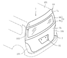
図1に示すように、バックドア1は、ハッチバック車の車体101後端に設けられたバックドア開口103を開閉する上下開閉式の車両用バックドアである。バックドア1の上半部には、車内へ採光可能な窓部3が設けられている。また、バックドア1の下半部は、バックドア開口103における左右両側に設けられたリヤランプ105を車両後方に露出させるために、下方に向かうに連れて左右の幅が狭くなっている。
As shown in FIG. 1, the
図2に示すように、バックドア1は、窓用開口13が形成されたドア本体10と、ドア本体10の窓用開口13を塞ぐ窓パネル9とを備えている。ドア本体10は、車内側に位置する樹脂製のインナパネル5と、車外側に位置する樹脂製のアウタパネル7とを有する。インナパネル5、アウタパネル7、及び窓パネル9は、互いに接着されている。
As shown in FIG. 2, the
インナパネル5は、射出成形などで成形される一枚物のパネルであって、例えば、ガラス繊維入りポリプロピレン(PP−GF;Polypropylene Glass Fiber)や炭素繊維入りポリプロピレン(PP−CF:Polypropylene Carbon Fiber)などの繊維補強材を含有する熱可塑性樹脂からなる。
The
インナパネル5は、アウタパネル7と前後方向において対向し、インナパネル5の主体をなす本体部11を有する。本体部11は、車両前方に臨む面を構成している。
The
インナパネル5の本体部11における上半部分は、略台形状に形成されていて、車幅方向に延びる窓用開口13を有する。窓用開口13は、インナパネル5の本体部11における上半部分と相似形の略台形状に形成されている。
The upper half portion of the
インナパネル5の本体部11の外周縁には、アウタパネル7側に立ち上がる外側立ち壁15が全周に亘って環状に設けられている。外側立ち壁15の後端には、接合用の外側フランジ17が外側方に張り出すように設けられている。
On the outer peripheral edge of the
また、インナパネル5のうち本体部11の窓用開口13周りには、アウタパネル7側に立ち上がる内側立ち壁19が全周に亘って環状に設けられている。内側立ち壁19の後端には、接合用の内側フランジ21が窓用開口13の内方に張り出すように設けられている。そして、インナパネル5のうち窓用開口13の左右両側の部分は、車両後方に開口を向ける水平断面凹状のピラー部23でそれぞれ構成されている。
Further, an
図3に示すように、ピラー部23は、凹状部分の底面を構成する底面部24と、車幅方向における外側に位置する外側壁26と、車幅方向における内側に位置する内側壁28とで構成されている。
As shown in FIG. 3, the
底面部24は、インナパネル5の本体部11の一部で形成されている。外側壁26は、外側立ち壁15及び外側フランジ17の一部で形成されている。また、内側壁28は、内側立ち壁19及び内側フランジ21の一部で形成されている。
The
ピラー部23には、外側壁26と内側壁28とを左右に橋渡しして連結する橋絡片25が、ピラー部23の上下に間隔をあけて一対に設けられている。橋絡片25には、位置決め孔32と、挿通孔34とが、左右方向に並んで形成されている。
The
ピラー部23の底面部24のうち車幅方向における外側部分を含めたインナパネル5の外周部分には、バックドア1がバックドア開口103を閉じた状態のときに、車内への雨風や埃、騒音などの浸入を防ぐために車体101に取り付けられたウェザストリップ107が前方から密着する(図4及び図5参照)。
On the outer peripheral portion of the
図2に示すように、アウタパネル7は、上下に2分割され、上側に位置するアッパアウタパネル7aと、下側に位置するロアアウタパネル7bとで構成されている。これらアッパアウタパネル7a及びロアアウタパネル7bは、例えば、タルク入りポリプロピレン(PP−T:Polypropylene Talc)やそれにエチレンプロピレンジエンメチレンゴム(EPDM:Ethylene Propylene Diene Monomer)を混合した合成樹脂からなり、例えば射出成形によって成形される。
As shown in FIG. 2, the
アッパアウタパネル7aは、車幅方向に延びる横長の帯板状に形成されている。アッパアウタパネル7aは、インナパネル5のうち窓用開口13よりも上側の部分に対向し、インナパネル5の外側フランジ17と内側フランジ21とにそれぞれ塗布された接着剤によって、インナパネル5に取り付けられている。
The upper
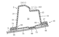
アッパアウタパネル7aがインナパネル5に取り付けられることで、インナパネル5の本体部11、外側立ち壁15、及び内側壁28と、アッパアウタパネル7aとの間には、中空部30が設けられる(図4のロアアウタパネル7bの例を参照)。
By attaching the upper
アッパアウタパネル7aの下縁部には、前方に凹むアッパ側段差部61が車幅方向における全体に亘って設けられている。このアッパ側段差部61の左右方向における両端部には、ピラー部23に沿って上側の橋絡片25に対応する箇所にまで下方に延びる延出部62が設けられている。延出部65は、対応する橋絡片25と係合させることでアッパアウタパネル7aをインナパネル5に接着する際の位置決めに用いられる。
An upper
ロアアウタパネル7bは、インナパネル5の下半部分の形状に対応して下方に向かうに連れて左右の幅が狭くなる形状に形成されている。ロアアウタパネル7bは、インナパネル5のうち窓用開口13よりも下側の部分に対向し、インナパネル5の外側フランジ17と内側フランジ21とにそれぞれ塗布されたウレタン系樹脂接着剤88及びホットメルト接着剤90によって、インナパネル5に取り付けられている(図3参照)。
The lower
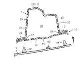
ロアアウタパネル7bがインナパネル5に取り付けられることで、インナパネル5の本体部11、外側立ち壁15、及び内側壁28と、ロアアウタパネル7bとの間には、中空部30が設けられる(図4参照)。
By attaching the lower
ロアアウタパネル7bの中央部には、前方に向かって凹んだプレート取付凹部81が設けられている。プレート取付凹部81の開放面は、上辺が下辺よりも大きい台形状に形成されている。
A
ロアアウタパネル7bの上縁部には、前方に凹むロア側段差部63が車幅方向における全体に亘って設けられている。このロア側段差部63の左右方向における両端部には、ピラー部23に沿って下側の橋絡片25に対応する箇所にまで上方に延びる延出部65が設けられている。延出部65は、対応する橋絡片25と係合させることでロアアウタパネル7bをインナパネル5に接着する際の位置決めに用いられる。
A
以下、ロアアウタパネル7bの右側の延出部65及びそれに係合する橋絡片25を例に挙げて、図3〜図5を参照しながら説明する。
Hereinafter, the
ピラー部23の外側フランジ17及び内側フランジ21のうち橋絡片25よりも下側の部分には、ロアアウタパネル7bの延出部65の厚さとウレタン系樹脂接着剤88の厚さ分だけ前方に凹んだ段差部37が形成されている。
Of the
そして、インナパネル5の外側フランジ17及び内側フランジ21のうちロアアウタパネル7bが接着される部分は、上下一対の橋絡片25の間の部分よりも前方に凹んで、ロアアウタパネル7bの外周部が嵌め入れられる嵌入れ部38を構成している。
The portion of the
ウレタン系樹脂接着剤88は、外側フランジ17及び内側フランジ21の嵌入れ部38に沿って連続的に塗布されている。ホットメルト接着剤90は、ウレタン系樹脂接着剤88よりも中空部30寄りの位置で且つ嵌入れ部38に断続的に塗布されている。
The
ホットメルト接着剤90は、ウレタン系樹脂接着剤88よりも硬化時間が短いため、ウレタン系樹脂接着剤88が硬化するまでの間、インナパネル5とロアアウタパネル7bとが互いに位置ずれしないように仮止めすることができる。
Since the hot melt adhesive 90 has a shorter curing time than the
ロアアウタパネル7bの延出部65の後方に臨む面には、窓パネル9側に突出した嵩上げ部75が一体に設けられている。嵩上げ部75は、延出部65における中空部30に対応する位置に設けられている。
A raised
また、延出部65の先端には、橋絡片25と対向する面を有するL字形板状の突出片67が上方に突出させて設けられている。突出片67は、橋絡片25と対向する面に、ピラー部23側に突出したピン形状の位置決め突起69と、固定用の挿通孔71とを有する。位置決め突起69は、突出片67のうち位置決め孔32に対応する部分に設けられている。ロアアウタパネル7bは、位置決め突起69を位置決め孔32に挿入することで位置決めされる。
Further, an L-shaped projecting
固定用の挿通孔71は、突出片67における挿通孔34に対応する部分に形成されている。そして、橋絡片25と突出片67とは、両方の挿通孔34,71を後方から挿通させたタッピングネジ73で締結される。
The fixing
また、図示しないが、インナパネル5の外側フランジ17及び内側フランジ21のうちアッパアウタパネル7aが接着される部分も、ピラー部23の外側フランジ17及び内側フランジ21のうち上下一対の橋絡片25の間の部分よりも前方に凹んで、アッパアウタパネル7aの外周部が嵌め入れられる嵌入れ部38を構成している。
Although not shown, the portion of the
そして、アッパアウタパネル7aの延出部62及びロアアウタパネル7bの延出部65は、嵌入れ部38に嵌め入れられてインナパネル5に固定された状態で、ピラー部23の外側壁26及び内側壁28のうち上下一対の橋絡片25の両側及びそれら一対の橋絡片25の間の部分と面一の連続した窓パネル接着面を形成する。
The
窓パネル9は、ガラス製又は樹脂製のパネルであって、図2に示すように、バックドア1の左右両端に亘って車幅方向に延びる横長の略台形状に形成されている。窓パネル9は、アッパアウタパネル7aのアッパ側段差部61とロアアウタパネル7bのロア側段差部63との間に嵌め込まれて、窓用開口13を塞ぐと共に、図4及び図5に示すように左右両側のピラー部23の開口を覆っている。
The
窓パネル9のうち窓用開口13に対応する領域は透明な窓領域9aであって、窓領域9aの外側に位置する領域は黒色のセラミックス等からなる隠蔽層によって隠蔽された隠蔽領域9bとなっている。隠蔽領域9bによって、インナパネル5、アッパアウタパネル7a及びロアアウタパネル7bと、窓パネル9との接着部分やピラー部23の内側構造が車外側から視認されないように隠蔽されている。
A region corresponding to the
そして、窓パネル9の外周部分は、窓パネル接着面、アッパ側段差部61及びロア側段差部63とそれに連続する外側フランジ17及び内側フランジ21とに後方からウレタン系樹脂接着剤88及びホットメルト接着剤90で接着されている。
The outer peripheral portion of the
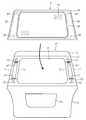
具体的に、図6及び図7に示すように、ウレタン系樹脂接着剤88は、窓パネル9における窓用開口13の周縁部に対応する位置、具体的には、インナパネル5の外側フランジ17及び内側フランジ21、アッパアウタパネル7aの周縁部、及びロアアウタパネル7bの周縁部に沿った位置に対応して連続的に塗布されている。
Specifically, as shown in FIGS. 6 and 7, the urethane-based resin adhesive 88 is located at a position corresponding to the peripheral edge of the
ホットメルト接着剤90は、窓パネル9における窓用開口13の周縁部の複数箇所、具体的には、アッパアウタパネル7aの延出部62及びロアアウタパネル7bの延出部65にそれぞれ設けられた嵩上げ部75に対応する位置の4箇所に塗布されている。ホットメルト接着剤90は、嵩上げ部75に塗布されることとなるので、ホットメルト接着剤90の厚みよりもウレタン系樹脂接着剤88の厚みが大きくなる(図4参照)。
The hot-
そして、インナパネル5、アウタパネル7、及び窓パネル9を貼り合わせた接合体を、ホットメルト接着剤90で仮止めした状態でウレタン系樹脂接着剤88を完全に硬化させることにより、インナパネル5、アウタパネル7、及び窓パネル9が互いに接着されたバックドア1が構成される。
Then, the
−本実施形態の効果−
以上のように、本実施形態に係るバックドア1によれば、ドア本体10と窓パネル9とを、窓用開口13の周縁部に沿った位置に対応して連続的に塗布されたウレタン系樹脂接着剤88と、窓用開口13の周縁部の複数箇所に対応して塗布されたホットメルト接着剤90とによって接着するようにしたから、ウレタン系樹脂接着剤88が硬化するまでの間、ウレタン系樹脂接着剤88よりも硬化時間の短いホットメルト接着剤90によって、ドア本体10と窓パネル9とが互いに位置ずれしないように仮止めすることができる。
-Effects of this embodiment-
As described above, according to the
また、ホットメルト接着剤90は、ウレタン系樹脂接着剤88よりも粘度が低く、塗布したときに広がり易い傾向にあるので、ドア本体10に嵩上げ部75を設けて、ホットメルト接着剤90を嵩上げ部75に対応する位置に塗布するようにしている。これにより、ホットメルト接着剤90の厚みと嵩上げ部75の高さとの合計分だけ、ウレタン系樹脂接着剤88の厚みを確保して、衝撃吸収性能を高めることができる。
Moreover, since the hot melt adhesive 90 has a lower viscosity than the
また、嵩上げ部75は、アウタパネル7における中空部30に対応する位置に設けられているので、窓パネル9に衝撃が加わった場合に、アウタパネル7が中空部30側に撓むことで、この撓み代の分だけ、衝撃を吸収することが可能となる。
Further, since the raised
《その他の実施形態》
前記実施形態については、以下のような構成としてもよい。
<< Other Embodiments >>
About the said embodiment, it is good also as following structures.
本実施形態では、ドア本体10に窓パネル9を取り付けるときに、窓パネル9側にウレタン系樹脂接着剤88及びホットメルト接着剤90を塗布するようにしたが、この形態に限定するものではない。例えば、ドア本体10側にウレタン系樹脂接着剤88及びホットメルト接着剤90を塗布してもよく、窓パネル9側にウレタン系樹脂接着剤88を塗布し、ドア本体10側にホットメルト接着剤90を塗布するようにしても構わない。
In this embodiment, when the
以上説明したように、本発明は、比較的簡単な構成で、ウレタン系樹脂接着剤が硬化するまでの間、ドア本体と窓パネルとが互いに位置ずれするのを抑えることができるという実用性の高い効果が得られることから、きわめて有用で産業上の利用可能性は高い。 As described above, the present invention has a relatively simple configuration and can prevent the door body and the window panel from being displaced from each other until the urethane resin adhesive is cured. Since it is highly effective, it is extremely useful and has high industrial applicability.
1 車両用バックドア
5 インナパネル
7 アウタパネル
9 窓パネル
10 ドア本体
13 窓用開口
30 中空部
75 嵩上げ部
88 ウレタン系樹脂接着剤
90 ホットメルト接着剤
DESCRIPTION OF
Claims (2)
前記窓パネル(9)は、前記ドア本体(10)の窓用開口(13)の周縁部に沿った位置に対応して連続的に塗布されたウレタン系樹脂接着剤(88)と、該ドア本体(10)の窓用開口(13)の周縁部の複数箇所に対応して塗布されたホットメルト接着剤(90)とによって該ドア本体(10)に接着され、
前記ドア本体(10)における前記ホットメルト接着剤(90)の塗布対応位置には、該ホットメルト接着剤(90)の厚みよりも前記ウレタン系樹脂接着剤(88)の厚みが大きくなるように、前記窓パネル(9)側に突出した嵩上げ部(75)が設けられていることを特徴とする車両用バックドア。 A vehicle back door comprising a door body (10) formed with a window opening (13) and a window panel (9) for closing the window opening (13) of the door body (10),
The window panel (9) includes a urethane resin adhesive (88) continuously applied corresponding to a position along the peripheral edge of the window opening (13) of the door body (10), and the door Adhered to the door body (10) by a hot melt adhesive (90) applied corresponding to a plurality of locations on the periphery of the window opening (13) of the body (10),
At the position corresponding to the application of the hot melt adhesive (90) in the door body (10), the thickness of the urethane resin adhesive (88) is larger than the thickness of the hot melt adhesive (90). The vehicle back door is provided with a raised portion (75) protruding toward the window panel (9).
前記ドア本体(10)は、樹脂製のインナパネル(5)と、該インナパネル(5)との間に中空部(30)を有するように該インナパネル(5)に接着された樹脂製のアウタパネル(7)とを有し、
前記嵩上げ部(75)は、前記アウタパネル(7)における前記中空部(30)に対応する位置に設けられていることを特徴とする車両用バックドア。 In claim 1,
The door body (10) is made of a resin-made inner panel (5) and a resin-made adhesive bonded to the inner panel (5) so as to have a hollow portion (30) between the inner panel (5). An outer panel (7),
The vehicle back door, wherein the raised portion (75) is provided at a position corresponding to the hollow portion (30) in the outer panel (7).
Priority Applications (1)
| Application Number | Priority Date | Filing Date | Title |
|---|---|---|---|
| JP2015233687A JP2017100511A (en) | 2015-11-30 | 2015-11-30 | Vehicular back door |
Applications Claiming Priority (1)
| Application Number | Priority Date | Filing Date | Title |
|---|---|---|---|
| JP2015233687A JP2017100511A (en) | 2015-11-30 | 2015-11-30 | Vehicular back door |
Publications (1)
| Publication Number | Publication Date |
|---|---|
| JP2017100511A true JP2017100511A (en) | 2017-06-08 |
Family
ID=59015868
Family Applications (1)
| Application Number | Title | Priority Date | Filing Date |
|---|---|---|---|
| JP2015233687A Pending JP2017100511A (en) | 2015-11-30 | 2015-11-30 | Vehicular back door |
Country Status (1)
| Country | Link |
|---|---|
| JP (1) | JP2017100511A (en) |
Cited By (2)
| Publication number | Priority date | Publication date | Assignee | Title |
|---|---|---|---|---|
| WO2018073647A1 (en) * | 2016-10-19 | 2018-04-26 | Magna Exteriors Inc. | Variable ratio adhesive application |
| JP2023157322A (en) * | 2022-04-14 | 2023-10-26 | Agc株式会社 | Method of manufacturing glass with brackets and glass with brackets |
-
2015
- 2015-11-30 JP JP2015233687A patent/JP2017100511A/en active Pending
Cited By (2)
| Publication number | Priority date | Publication date | Assignee | Title |
|---|---|---|---|---|
| WO2018073647A1 (en) * | 2016-10-19 | 2018-04-26 | Magna Exteriors Inc. | Variable ratio adhesive application |
| JP2023157322A (en) * | 2022-04-14 | 2023-10-26 | Agc株式会社 | Method of manufacturing glass with brackets and glass with brackets |
Similar Documents
| Publication | Publication Date | Title |
|---|---|---|
| JP6242107B2 (en) | Vehicle back door assembly structure | |
| JP5903374B2 (en) | Vehicle back door | |
| JP6051070B2 (en) | Vehicle window member fixing structure | |
| US11718244B2 (en) | Trim part | |
| JP6446555B2 (en) | Method for manufacturing composite parts and composite parts | |
| JP6373165B2 (en) | Vehicle back door | |
| JP6254428B2 (en) | Resin panel and manufacturing method thereof | |
| JP6150696B2 (en) | Vehicle back door | |
| JP6150682B2 (en) | Vehicle back door | |
| JP2016124346A (en) | Vehicular back door | |
| JP6800068B2 (en) | Vehicle backdoor and its manufacturing method | |
| JP6219640B2 (en) | Vehicle back door | |
| JP2017056905A (en) | Vehicular back door | |
| JP6639207B2 (en) | Vehicle back door | |
| JP5474912B2 (en) | Decorative member for vehicle window panel | |
| JP6639206B2 (en) | Vehicle back door | |
| JP5603204B2 (en) | Door parting seal and its mounting structure | |
| JP7182473B2 (en) | vehicle back door | |
| JP2007076441A (en) | Glass run | |
| JP4494350B2 (en) | Vehicle windshield mounting structure | |
| JP2017039472A (en) | Vehicle back door | |
| JP2008024112A (en) | Glass run | |
| KR100795697B1 (en) | Door frame sealing structure of automobile | |
| KR102010605B1 (en) | Mounting structure of weather strip for vehicle | |
| KR100776653B1 (en) | Door frame sealing structure of automobile |