JP2017102748A - Pupil image learning device, pupil position detection device, and program therefor - Google Patents
Pupil image learning device, pupil position detection device, and program therefor Download PDFInfo
- Publication number
- JP2017102748A JP2017102748A JP2015236043A JP2015236043A JP2017102748A JP 2017102748 A JP2017102748 A JP 2017102748A JP 2015236043 A JP2015236043 A JP 2015236043A JP 2015236043 A JP2015236043 A JP 2015236043A JP 2017102748 A JP2017102748 A JP 2017102748A
- Authority
- JP
- Japan
- Prior art keywords
- pupil
- image
- feature amount
- region
- learning
- Prior art date
- Legal status (The legal status is an assumption and is not a legal conclusion. Google has not performed a legal analysis and makes no representation as to the accuracy of the status listed.)
- Pending
Links
Images




Landscapes
- Image Processing (AREA)
- Image Analysis (AREA)
Abstract
【課題】本願発明は、高解像度の瞳拡大画像を撮影できない場合でも、簡易な構成で瞳位置を検出する。【解決手段】瞳検出装置1は、瞳画像学習装置2が、エッジに関する画像特徴量を算出する画像特徴量算出部20と、画像特徴量を機械学習することで、瞳画像判別モデルを生成する瞳画像判別モデル生成部26とを備え、瞳位置検出装置4が、人物の顔領域を切り出した顔画像に瞳候補領域を設定する瞳候補領域設定部40と、瞳候補領域に設定された窓領域について、エッジに関する画像特徴量を算出する画像特徴量算出部44と、窓領域の画像特徴量を瞳画像判別モデルに入力し、窓領域が瞳画像であるか否かを判別する瞳画像判別部46と、瞳画像であると判別された窓領域に含まれる瞳位置を算出する瞳位置算出部48と備える。【選択図】図1Kind Code: A1 An object of the present invention is to detect a pupil position with a simple configuration even when a high-resolution pupil-enlarged image cannot be captured. Kind Code: A1 In a pupil detection device, a pupil image learning device generates a pupil image discrimination model through machine learning of an image feature quantity calculation unit for calculating an image feature quantity relating to an edge and an image feature quantity. The pupil position detection device 4 includes a pupil image discrimination model generation unit 26, and a pupil candidate region setting unit 40 for setting a pupil candidate region in a face image obtained by cutting out a person's face region, and a window set in the pupil candidate region. An image feature amount calculator 44 that calculates an image feature amount related to an edge for a region, and a pupil image determination that inputs the image feature amount of the window region into a pupil image determination model and determines whether or not the window region is a pupil image. and a pupil position calculator 48 for calculating the pupil position included in the window region determined to be the pupil image. [Selection drawing] Fig. 1
Description
本願発明は、瞳画像を判別する瞳画像判別モデルを生成する瞳画像学習装置、この瞳画像判別モデルを用いて、撮影画像に含まれる人物の瞳位置を検出する瞳位置検出装置及びそのプログラムに関する。 The present invention relates to a pupil image learning device that generates a pupil image discrimination model that discriminates a pupil image, a pupil position detection device that detects a pupil position of a person included in a captured image using the pupil image discrimination model, and a program thereof. .
従来より、映像(動画)から瞳位置を検出する手法は、運転者の視線方向の特定、番組視聴者や会議参加者の集中度推定、照明光強度の調整など、様々な分野で利用されている(特許文献1〜7)。
Conventionally, a method for detecting a pupil position from a video (video) has been used in various fields such as specifying a driver's gaze direction, estimating a concentration of program viewers and conference participants, and adjusting illumination light intensity. (
特許文献1,2に記載の発明は、対象者の頭部に装着した撮影カメラ(ヘッドマウントデバイス)で瞳拡大画像を撮影し、瞳位置を検出するものである。また、特許文献3,4に記載の発明は、車室内に取り付けた撮影カメラで対象者(運転者)の瞳拡大画像を撮影し、視線方向を特定するものである。また、特許文献5〜7に記載の発明は、複数台の撮影カメラで対象者の顔を撮影し、各撮影カメラで撮影した顔画像から、対象者の視線方向を特定するものである。
In the inventions described in
しかし、特許文献1〜4に記載の発明は、対象者の頭部に撮影カメラを装着し、又は、対象者の顔の近くに撮影カメラを配置することで、撮影カメラを対象者の顔に接近させた状態で高解像度の瞳拡大画像を撮影する必要がある。言い換えると、特許文献1〜4に記載の発明は、高解像度の瞳拡大画像を撮影できない場合、瞳位置を検出することができない。
また、特許文献5〜7に記載の発明は、複数台の撮影カメラが必要となるので、装置の大型化、複雑化を招いてしまう。
However, in the inventions described in
In addition, since the inventions described in Patent Documents 5 to 7 require a plurality of photographing cameras, the apparatus is increased in size and complexity.
そこで、本願発明は、高解像度の瞳拡大画像を撮影できない場合でも、簡易な構成で瞳位置を検出可能とする瞳画像学習装置、瞳位置検出装置及びそのプログラムを提供することを課題とする。 Accordingly, an object of the present invention is to provide a pupil image learning device, a pupil position detection device, and a program thereof that can detect a pupil position with a simple configuration even when a high-resolution pupil magnified image cannot be captured.
前記した課題に鑑みて、本願発明に係る瞳画像学習装置は、人物の瞳領域を切り出した瞳画像と、人物の瞳以外の顔領域を切り出した非瞳画像との集合である学習用画像集合から、瞳画像を判別する瞳画像判別モデルを生成する瞳画像学習装置であって、第1画像特徴量算出部と、瞳画像判別モデル生成部と、を備える構成とした。 In view of the foregoing problems, the pupil image learning device according to the present invention is a learning image set that is a set of a pupil image obtained by cutting out a human pupil region and a non-pupil image obtained by cutting out a face region other than the human pupil. Therefore, the pupil image learning apparatus for generating a pupil image discrimination model for discriminating a pupil image is configured to include a first image feature quantity calculation unit and a pupil image discrimination model generation unit.
かかる構成によれば、瞳画像学習装置は、第1画像特徴量算出部によって、学習用画像集合に含まれる瞳画像及び非瞳画像のそれぞれについて、エッジに関する画像特徴量を算出する。
また、瞳画像学習装置は、瞳画像判別モデル生成部によって、瞳画像の画像特徴量及び非瞳画像の画像特徴量を機械学習することで、瞳画像判別モデルを生成する。この瞳画像判別モデルは、エッジに関する画像特徴量を学習しているため、1台の撮影カメラで人物が撮影された撮影画像から、高い正確性で瞳画像の判別を可能とする。
According to such a configuration, in the pupil image learning device, the first image feature amount calculation unit calculates the image feature amount related to the edge for each of the pupil image and the non-pupil image included in the learning image set.
The pupil image learning device generates a pupil image discrimination model by machine learning of the image feature amount of the pupil image and the image feature amount of the non-pupil image by the pupil image discrimination model generation unit. Since this pupil image discrimination model learns the image feature quantity related to the edge, it is possible to discriminate the pupil image with high accuracy from a shot image obtained by shooting a person with one shooting camera.
また、前記した課題に鑑みて、本願発明に係る瞳位置検出装置は、本願発明に係る瞳画像学習装置が生成した瞳画像判別モデルを用いて、撮影画像に含まれる人物の瞳位置を検出する瞳位置検出装置であって、瞳候補領域設定部と、第2画像特徴量算出部と、瞳画像判別部と、瞳位置算出部と、を備える構成とした。 Further, in view of the above-described problems, the pupil position detection device according to the present invention detects the pupil position of a person included in the captured image using the pupil image discrimination model generated by the pupil image learning device according to the present invention. The pupil position detection device includes a pupil candidate area setting unit, a second image feature amount calculation unit, a pupil image determination unit, and a pupil position calculation unit.
かかる構成によれば、瞳位置検出装置は、瞳候補領域設定部によって、1台の撮影カメラで撮影された撮影画像に含まれる人物の顔領域を切り出した顔画像に、当該顔領域よりも小さいサイズの瞳候補領域を設定する。
また、瞳位置検出装置は、第2画像特徴量算出部によって、瞳候補領域について、エッジに関する画像特徴量を算出する。
According to such a configuration, the pupil position detection device is smaller than the face area in the face image obtained by cutting out the face area of the person included in the photographed image photographed by one photographing camera by the pupil candidate area setting unit. Set the size pupil candidate area.
In the pupil position detection device, the second image feature amount calculation unit calculates an image feature amount related to the edge for the pupil candidate region.
また、瞳位置検出装置は、瞳画像判別部によって、瞳候補領域の画像特徴量を瞳画像判別モデルに入力することで、瞳候補領域が瞳画像であるか否かを判別する。この瞳画像判別モデルは、エッジに関する画像特徴量を学習しているため、1台の撮影カメラで人物が撮影された撮影画像から、高い正確性で瞳画像の判別を可能とする。
そして、瞳位置検出装置は、瞳位置算出部によって、瞳画像と判別された瞳候補領域に含まれる瞳位置を算出する。
Further, the pupil position detection device determines whether or not the pupil candidate region is a pupil image by inputting the image feature amount of the pupil candidate region to the pupil image determination model by the pupil image determination unit. Since this pupil image discrimination model learns the image feature quantity related to the edge, it is possible to discriminate the pupil image with high accuracy from a shot image obtained by shooting a person with one shooting camera.
Then, the pupil position detection device calculates the pupil position included in the candidate pupil region determined as the pupil image by the pupil position calculation unit.
本願発明によれば、以下のような優れた効果を奏する。
本願発明に係る瞳画像学習装置は、エッジに関する画像特徴量を学習した瞳画像判別モデルを生成し、本願発明に係る瞳位置検出装置は、1台の撮影カメラで人物が撮影された撮影画像から、この瞳画像判別モデルを用いて瞳位置を検出する。このように、本願発明によれば、高解像度の瞳拡大画像を撮影できない場合でも、複数台の撮影カメラを必要とせずに簡易な構成で瞳位置を検出可能とする。
According to the present invention, the following excellent effects can be obtained.
The pupil image learning device according to the present invention generates a pupil image discrimination model in which the image feature quantity related to the edge is learned, and the pupil position detection device according to the present invention is based on a photographed image obtained by photographing a person with one photographing camera. The pupil position is detected using this pupil image discrimination model. Thus, according to the present invention, even when a high-resolution pupil magnified image cannot be captured, the pupil position can be detected with a simple configuration without requiring a plurality of imaging cameras.
以下、本願発明の実施形態について、適宜図面を参照しながら詳細に説明する。なお、同一の機能を有する手段には同一の符号を付し、説明を省略した。 Hereinafter, embodiments of the present invention will be described in detail with reference to the drawings as appropriate. In addition, the same code | symbol was attached | subjected to the means which has the same function, and description was abbreviate | omitted.
[瞳検出装置の構成]
図1を参照し、本願発明の実施形態に係る瞳検出装置1の構成について、説明する。
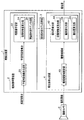
瞳検出装置1は、瞳画像の判別に利用する瞳画像判別モデルを生成すると共に、その瞳画像判別モデルを用いて、撮影画像に含まれる瞳位置を検出するものである。図1のように、瞳検出装置1は、瞳画像学習装置2と、瞳画像判別モデル記憶部3と、瞳位置検出装置4とを備える。
[Configuration of pupil detection device]
With reference to FIG. 1, the structure of the
The
<瞳画像学習装置>
瞳画像学習装置2は、後記する学習用画像集合から、瞳画像を判別する瞳画像判別モデルを生成するものである。図1のように、瞳画像学習装置2は、学習用画像集合生成部20と、瞳画像学習部22とを備える。
<Pupil image learning device>
The pupil
学習用画像集合生成部20は、外部より入力された顔画像集合から学習用画像集合を生成するものである。
顔画像集合とは、人物の顔領域が撮影された顔画像の集合である。この顔画像集合は、瞳画像判別モデルの正確性を向上させるため、様々な人物の顔画像や、同一人物であっても顔の向きが異なる顔画像を含んでいることが好ましい。
学習用画像集合とは、人物の瞳領域を切り出した瞳画像と、人物の瞳以外の顔領域を切り出した非瞳画像との集合である。
The learning image
The face image set is a set of face images obtained by photographing a person's face area. In order to improve the accuracy of the pupil image discrimination model, it is preferable that this face image set includes face images of various persons and face images having different face directions even for the same person.
The learning image set is a set of a pupil image obtained by cutting out a person's pupil area and a non-pupil image obtained by cutting out a face area other than the person's pupil.
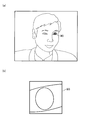
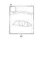
例えば、学習用画像集合生成部20は、入力された顔画像集合に含まれる各顔画像を、予め設定されたサイズ(幅W1×高さH1)に変換する。次に、学習用画像集合生成部20は、変換した顔画像をディスプレイ(不図示)に表示し、図2(a)のように、予め設定されたサイズ(幅R×高さR)の矩形状の瞳領域90を瞳画像学習装置2の利用者に選択させる。そして、学習用画像集合生成部20は、図2(b)のように、選択された瞳領域90を瞳画像として切り出す。
For example, the learning image
また、学習用画像集合生成部20は、図3(a)のように、ディスプレイに表示された顔画像から、瞳領域90と同一サイズの瞳以外の顔領域(非瞳領域)91を瞳画像学習装置2の利用者に選択させる。そして、学習用画像集合生成部20は、図3(b)のように、選択された非瞳領域91を非瞳画像として切り出す。
Further, as shown in FIG. 3A, the learning image
その後、学習用画像集合生成部20は、切り出した瞳画像及び非瞳画像の集合を、学習用画像集合として瞳画像学習部22に出力する。
なお、学習用画像集合生成部20は、教師あり機械学習を行うために、瞳画像に正解データであることを示す識別情報を付加し、非瞳画像に不正解データであることを示す識別情報を付加してもよい。
また、学習用画像集合生成部20は瞳画像学習装置2の外部にあって、瞳画像学習装置2は学習用画像集合を外部から取り込むこととしてもよい。
Thereafter, the learning image set
The learning image
Further, the learning image
瞳画像学習部22は、学習用画像集合生成部20から入力された学習用画像集合を学習するものであり、画像特徴量算出部(第1画像特徴量算出部)24と、瞳画像判別モデル生成部26とを備える。
The pupil
画像特徴量算出部24は、学習用画像集合に含まれる瞳画像及び非瞳画像のそれぞれについて、エッジに関する画像特徴量(例えば、既知のエッジ方向ヒストグラム)を算出するものである。 The image feature amount calculation unit 24 calculates an image feature amount related to an edge (for example, a known edge direction histogram) for each of the pupil image and the non-pupil image included in the learning image set.
ここで、瞳位置を正確に検出するために、瞳を囲む円や眼の輪郭等の形状を重視した画像特徴量を用いることが好ましい。そこで、画像特徴量算出部24は、エッジに関する画像特徴量として、多重スケールエッジヒストグラムを算出する。
この多重スケールエッジヒストグラムとは、異なるスケールで延長されたエッジのヒストグラムのことであり、多重スケールエッジ方向ヒストグラムや多重スケールエッジ接続角度ヒストグラムが含まれる。
Here, in order to accurately detect the pupil position, it is preferable to use an image feature amount that places importance on the shape such as a circle surrounding the pupil and an eye contour. Therefore, the image feature amount calculation unit 24 calculates a multiscale edge histogram as the image feature amount related to the edge.
This multi-scale edge histogram is a histogram of edges extended at different scales, and includes a multi-scale edge direction histogram and a multi-scale edge connection angle histogram.
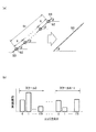
多重スケールエッジ方向ヒストグラムは、図4(a)のように、Kピクセルだけ離れた画素92の局所的なエッジ93だけでなく、Knピクセル離れた画素92までが連続した場合、スケールnのエッジ93として扱う。この多重スケールエッジ方向ヒストグラムは、図4(b)のように、スケール0からスケールN−1まで、0度〜179度のエッジ方向θ毎に、エッジ93の出現頻度(画像中の個数)を表している。
なお、Nはスケールの多重数であり、1≦n≦Nを満たす。
As shown in FIG. 4A, the multi-scale edge direction histogram shows an
N is the number of multiplexed scales and satisfies 1 ≦ n ≦ N.
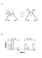
多重スケールエッジ接続角度ヒストグラムは、図5(a)のように、エッジ93Aと、そのエッジ93Aの端点となる画素92Aを中心とした半径Rの円内に、端点となる画素92Bが存在するエッジ93Bとの接続角度φに基づいたものである。この多重スケールエッジ接続角度ヒストグラムは、図5(b)のように、スケール0からスケールN−1まで、方向1度〜180度の角度毎に、エッジ93同士の接続角度φの出現頻度(画像中の個数)を表している。
As shown in FIG. 5A, the multi-scale edge connection angle histogram is an edge in which a
ここで、画像特徴量算出部24は、エッジに関する画像特徴量として、多重スケールエッジ方向ヒストグラム又は多重スケールエッジ接続角度ヒストグラムの一方のみを算出してもよい。また、画像特徴量算出部24は、多重スケールエッジ方向ヒストグラム又は多重スケールエッジ接続角度ヒストグラムの両方を算出し、これらを要素とする多次元の画像特徴量として扱ってもよい。 Here, the image feature amount calculation unit 24 may calculate only one of the multiscale edge direction histogram or the multiscale edge connection angle histogram as the image feature amount related to the edge. In addition, the image feature amount calculation unit 24 may calculate both the multiscale edge direction histogram or the multiscale edge connection angle histogram, and handle them as multidimensional image feature amounts having these as elements.
なお、多重スケールエッジ方向ヒストグラム及び多重スケールエッジ接続角度ヒストグラムは、下記の参考文献に詳細に記載されているため、これ以上の説明を省略する。
参考文献:震災映像アーカイブス検索システムへの類似画像検索技術の適用、望月貴裕他、2014年映像情報メディア学会年次大会(ITE Annual Convention 2014)
Note that the multiscale edge direction histogram and the multiscale edge connection angle histogram are described in detail in the following references, and thus further description thereof is omitted.
References: Application of similar image search technology to the earthquake video archives search system, Takahiro Mochizuki et al., ITE Annual Convention 2014
瞳画像判別モデル生成部26は、画像特徴量算出部24が算出した瞳画像の画像特徴量及び非瞳画像の画像特徴量を機械学習することで、瞳画像判別モデルを生成するものである。この瞳画像判別モデル生成部26は、既知の機械学習を利用でき、サポートベクターマシン、ニューラルネットワーク等の教師あり機械学習を行うことが好ましい。そして、瞳画像判別モデル生成部26は、生成した瞳画像判別モデルを瞳画像判別モデル記憶部3に書き込む。 The pupil image discrimination model generation unit 26 generates a pupil image discrimination model by machine learning of the image feature amount of the pupil image and the image feature amount of the non-pupil image calculated by the image feature amount calculation unit 24. The pupil image discrimination model generation unit 26 can use known machine learning, and preferably performs supervised machine learning such as a support vector machine or a neural network. Then, the pupil image discrimination model generation unit 26 writes the generated pupil image discrimination model in the pupil image discrimination model storage unit 3.
<瞳画像判別モデル記憶部>
瞳画像判別モデル記憶部3は、瞳画像判別モデル生成部26が生成した瞳画像判別モデルを記憶するメモリ、ハードディスク(HDD:Hard Disk Drive)等の記憶装置である。
なお、瞳画像判別モデル記憶部3は、瞳画像学習装置2に備えられてもよく、瞳位置検出装置4に備えられてもよい。
<Pupil image discrimination model storage unit>
The pupil image discrimination model storage unit 3 is a storage device such as a memory or a hard disk (HDD: Hard Disk Drive) that stores the pupil image discrimination model generated by the pupil image discrimination model generation unit 26.
The pupil image discrimination model storage unit 3 may be provided in the pupil
<瞳位置検出装置>
瞳位置検出装置4は、瞳画像判別モデル記憶部3に記憶された瞳画像判別モデルを用いて、撮影画像に含まれる人物の瞳位置を検出するものである。図1のように、瞳位置検出装置4は、瞳候補領域設定部40と、瞳位置検出部42とを備える。
<Pupil position detector>
The pupil position detection device 4 detects the pupil position of a person included in the captured image using the pupil image discrimination model stored in the pupil image discrimination model storage unit 3. As shown in FIG. 1, the pupil position detection device 4 includes a pupil candidate
瞳候補領域設定部40は、1台の撮影カメラCで撮影された撮影画像に含まれる人物の顔領域を切り出した顔画像に、当該顔領域よりも小さいサイズの瞳候補領域を設定するものである。この撮影画像は、撮影映像(動画)を構成するフレーム画像である。
すなわち、瞳位置検出装置4は、以下で説明する処理を各フレーム画像に施すと、撮影映像の瞳位置を検出、追跡することが可能となる。
The pupil candidate
That is, the pupil position detection device 4 can detect and track the pupil position of the captured video when the processing described below is performed on each frame image.
まず、瞳候補領域設定部40は、一般的な撮影カメラCから入力された撮影画像に既知の顔領域検出処理(例えば、OpenCV)を施すことで、撮影画像に含まれる矩形状の顔領域を検出し、検出した顔領域を切り出して顔領域画像を生成する。この撮影画像に含まれる顔領域の左上座標を(x_f,y_f)とし、撮影画像に含まれる顔領域のサイズを(幅w_f×高さh_f)とする。
First, the pupil candidate
次に、瞳候補領域設定部40は、図6のように、生成した顔領域画像を予め設定されたサイズ(幅W_f×高さH_f)に変換することで、正規化顔領域画像94を生成する。そして、瞳候補領域設定部40は、正規化顔領域画像94に左右の瞳候補領域95(左瞳候補領域95L及び右瞳候補領域95R)を設定する。その後、瞳候補領域設定部40は、設定した左右の瞳候補領域95を瞳位置検出部42に出力する。
Next, the pupil candidate
ここで、図6のように、左瞳候補領域95L及び右瞳候補領域95Rの左上座標、幅及び高さは、以下の式で定義される。つまり、左瞳候補領域95L及び右瞳候補領域95Rは、縦横の比率がそのままで、正規化顔領域画像94の縮小したサイズとなる。なお、係数R1,R2,R3,R4は、0以上1未満の値で予め設定される。
Here, as shown in FIG. 6, the upper left coordinates, width, and height of the left
右瞳候補領域の左上座標 (x_r,y_r)=(R1×W_f,R3×H_f)
右瞳候補領域の幅 W_r=R2×W_f
右瞳候補領域の高さ H_r=R4×H_f
左瞳候補領域の左上座標 (x_l,y_l)=((1-R1-R2)×W_f,R3×H_f)
左瞳候補領域の幅 W_l=R2×W_f
左瞳候補領域の高さ H_l=R4×H_f
Upper left coordinates of right pupil candidate area (x_r, y_r) = (R1 x W_f, R3 x H_f)
Width of right pupil candidate area W_r = R2 × W_f
Height of right pupil candidate area H_r = R4 × H_f
Upper left coordinates of candidate left pupil region (x_l, y_l) = ((1-R1-R2) x W_f, R3 x H_f)
Left pupil candidate area width W_l = R2 × W_f
Height of left pupil candidate area H_l = R4 × H_f
瞳位置検出部42は、瞳候補領域設定部40より入力された左右の瞳候補領域95から、瞳位置を検出するものであり、画像特徴量算出部(第2画像特徴量算出部)44と、瞳画像判別部46と、瞳位置算出部48とを備える。
The pupil
画像特徴量算出部44は、左右の瞳候補領域について、エッジに関する画像特徴量を算出するものである。本実施形態では、画像特徴量算出部44は、学習用画像集合と同じサイズ(幅R×高さR)の窓領域を左右の瞳候補領域95に設定する。そして、画像特徴量算出部44は、異なる位置に設定された各窓領域について、画像特徴量算出部24と同一の画像特徴量を算出する。
The image feature
具体的には、画像特徴量算出部44は、図7のように、右瞳候補領域95Rに窓領域96を設定し、この窓領域96の画像特徴量を算出する。次に、画像特徴量算出部44は、窓領域96をスライドさせた後(破線で図示)、その位置で窓領域96の画像特徴量を算出する。このように、画像特徴量算出部44は、右瞳候補領域95Rの全範囲から画像特徴量を算出するまで、窓領域96のスライドと画像特徴量の算出とを繰り返す。
Specifically, the image feature
なお、画像特徴量算出部44では、窓領域96のスライド量を任意に設定できる。
また、画像特徴量算出部44では、窓領域96のスライド方法も任意に設定できる。例えば、画像特徴量算出部44は、右瞳候補領域95Rの左上から右下まで、ラスタスキャンのように窓領域96をスライドさせてもよい。
また、画像特徴量算出部44は、右瞳候補領域95Rと同様、左瞳候補領域95Lについても窓領域96の画像特徴量を算出する。
Note that the image feature
In addition, the image feature
The image feature
瞳画像判別部46は、左右の瞳候補領域95について、画像特徴量算出部44が算出した各窓領域96の画像特徴量を瞳画像判別モデルに入力することで、各窓領域96が瞳画像であるか否かを判別するものである。
The pupil
ここで、窓領域96の画像特徴量を瞳画像判別モデルに入力すると、その窓領域96が瞳画像である確率が瞳画像判別モデルから出力される。従って、瞳画像判別部46は、瞳画像判別モデルが出力した確率の閾値処理により、各窓領域96が瞳画像であるか否かを判別する。例えば、瞳画像判別部46は、瞳画像判別モデルからの確率が予め設定された閾値以上であれば、その窓領域96が瞳画像であると判別する。一方、瞳画像判別部46は、瞳画像判別モデルからの確率が閾値未満であれば、その窓領域96が瞳画像でないと判別する。
Here, when the image feature amount of the
瞳位置算出部48は、左右の瞳候補領域95について、瞳画像判別部46により瞳画像であると判別された窓領域96の瞳位置を算出するものである。
本実施形態では、瞳位置算出部48は、図8(a)のように、左右の瞳候補領域95について、瞳画像であると判別された全ての窓領域96の中心座標を求める。そして、瞳位置算出部48は、図8(b)のように、右瞳候補領域95Rから求めた中心座標の平均値を、正規化顔領域画像94における右瞳位置97Rとして算出する。さらに、瞳位置算出部48は、左瞳候補領域95Lから求めた中心座標の平均値を、正規化顔領域画像94における左瞳位置97Lとして算出する。
The pupil
In the present embodiment, as shown in FIG. 8A, the pupil
次に、瞳位置算出部48は、図9のように、正規化顔領域画像94における右瞳位置97Rを撮影画像98の座標に変換し、変換した座標を右瞳位置99Rとして出力する。また、瞳位置算出部48は、正規化顔領域画像94における左瞳位置97Lを撮影画像98の座標に変換し、変換した座標を左瞳位置99Lとして出力する。
Next, as shown in FIG. 9, the pupil
ここで、図9のように、左瞳候補領域95L及び右瞳候補領域95Rの左上座標、幅及び高さは、以下の式で定義される。なお、右瞳位置97Rの座標を(X_pr,Y_pr)とし、左瞳位置97Lの座標を(X_pl,Y_pl)とする。また、右瞳位置99Rの座標を(x_pr,y_pr)とし、左瞳位置99Lの座標を(x_pl,y_pl)とする。
Here, as shown in FIG. 9, the upper left coordinates, width, and height of the left
x_pr=x_f+(w_f/W_f)×X_pr
y_pr=y_f+(h_f/H_f)×Y_pr
x_pl=x_f+(w_f/W_f)×X_pl
y_pl=y_f+(h_f/H_f)×Y_pl
x_pr = x_f + (w_f / W_f) x X_pr
y_pr = y_f + (h_f / H_f) x Y_pr
x_pl = x_f + (w_f / W_f) x X_pl
y_pl = y_f + (h_f / H_f) x Y_pl
[瞳画像学習処理]
図10を参照し、瞳画像学習装置2による瞳画像学習処理について説明する(適宜図1参照)。
[Pupil image learning processing]
The pupil image learning process by the pupil
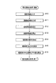
図10のように、瞳画像学習装置2は、外部より顔画像集合が学習用画像集合生成部20に入力される(ステップS1)。
瞳画像学習装置2は、学習用画像集合生成部20によって、人物の瞳領域を切り出した瞳画像を生成する(ステップS2)。
瞳画像学習装置2は、学習用画像集合生成部20によって、人物の非瞳域を切り出した非瞳画像を生成する(ステップS3)。
As shown in FIG. 10, in the pupil
In the pupil
In the pupil
瞳画像学習装置2は、画像特徴量算出部24によって、瞳画像及び非瞳画像のそれぞれについて、エッジに関する画像特徴量を算出する(ステップS4)。
瞳画像学習装置2は、瞳画像判別モデル生成部26によって、瞳画像の画像特徴量及び非瞳画像の画像特徴量を機械学習することで、瞳画像判別モデルを生成する(ステップS5)。
In the pupil
The pupil
[瞳位置検出処理]
図11を参照し、瞳位置検出装置4による瞳位置検出処理について説明する(適宜図1参照)。
[Pupil position detection processing]
With reference to FIG. 11, the pupil position detection process by the pupil position detection apparatus 4 will be described (see FIG. 1 as appropriate).
図11のように、瞳位置検出装置4は、1台の撮影カメラCから撮影画像が瞳候補領域設定部40に入力される(ステップS10)。
瞳位置検出装置4は、瞳候補領域設定部40によって、撮影画像に含まれる矩形状の顔領域を検出し、検出した顔領域を切り出して顔領域画像を生成する(ステップS11)。
瞳位置検出装置4は、瞳候補領域設定部40によって、顔領域画像から予め設定されたサイズの正規化顔領域画像を生成し、この正規化顔領域画像に左右の瞳候補領域を設定する(ステップS12)。
As shown in FIG. 11, the pupil position detection device 4 receives a photographed image from one photographing camera C to the pupil candidate area setting unit 40 (step S10).
In the pupil position detection device 4, the pupil candidate
In the pupil position detection device 4, the pupil candidate
瞳位置検出装置4は、画像特徴量算出部44によって、左右の瞳候補領域に窓領域を設定し、この窓領域の画像特徴量を算出する(ステップS13)。
瞳位置検出装置4は、瞳画像判別部46によって、各窓領域の画像特徴量を瞳画像判別モデルに入力し、各窓領域が瞳画像である確率を算出する(ステップS14)。
In the pupil position detection device 4, the image feature
In the pupil position detection device 4, the pupil
瞳位置検出装置4は、瞳画像判別部46によって、瞳画像判別モデルで求めた確率の閾値処理により、各窓領域が瞳画像であるか否かを判別する(ステップS15)。
瞳位置検出装置4は、瞳画像判別部46によって、瞳画像であると判別された全ての窓領域の中心座標の平均値を瞳位置として算出する(ステップS16)。
The pupil position detection device 4 determines whether each window region is a pupil image by the threshold value processing of the probability obtained by the pupil image determination model by the pupil image determination unit 46 (step S15).
The pupil position detection device 4 calculates, as the pupil position, the average value of the center coordinates of all the window regions that are determined to be pupil images by the pupil image determination unit 46 (step S16).
[作用・効果]
本願発明の実施形態に係る瞳検出装置1は、瞳画像学習装置2が、エッジに関する画像特徴量を学習した瞳画像判別モデルを生成し、瞳位置検出装置4が、この瞳画像判別モデルを用いて、1台の撮影カメラCで人物が撮影された撮影画像から瞳画像を判別する。従って、瞳検出装置1は、高解像度の瞳拡大画像を撮影できない場合でも、複数台の撮影カメラCを必要とせずに簡易な構成で瞳位置を検出することができる。
[Action / Effect]
In the
さらに、瞳検出装置1は、瞳画像学習装置2及び瞳位置検出装置4が、エッジに関する画像特徴量として、多重スケールエッジ方向ヒストグラムや多重スケールエッジ接続角度ヒストグラムのように、長いエッジやエッジの接続方法に重みをおいた画像特徴量を用いるため、瞳位置をより正確に検出することができる。
Further, in the
さらに、瞳検出装置1は、瞳位置検出装置4が、瞳画像であると判別された全ての窓領域の中心座標を求め、求めた中心座標の平均値を瞳位置として算出するため、瞳位置をより正確に検出することができる。
Further, the
前記した実施形態では、瞳位置検出装置4を独立したハードウェアとして説明したが、本願発明は、これに限定されない。例えば、コンピュータが備えるCPU、メモリ、ハードディスク等のハードウェア資源を、瞳位置検出装置4として協調動作させる瞳位置検出プログラムで実現することもできる。このプログラムは、通信回線を介して配布してもよく、CD−ROMやフラッシュメモリ等の記録媒体に書き込んで配布してもよい。 In the above-described embodiment, the pupil position detection device 4 has been described as independent hardware, but the present invention is not limited to this. For example, hardware resources such as a CPU, a memory, and a hard disk included in the computer can also be realized by a pupil position detection program that performs cooperative operation as the pupil position detection device 4. This program may be distributed through a communication line, or may be distributed by writing in a recording medium such as a CD-ROM or a flash memory.
1 瞳検出装置
2 瞳画像学習装置
3 瞳画像判別モデル記憶部
4 瞳位置検出装置
20 学習用画像集合生成部
22 瞳画像学習部
24 画像特徴量算出部(第1画像特徴量算出部)
26 瞳画像判別モデル生成部
40 瞳候補領域設定部
42 瞳位置検出部
44 画像特徴量算出部(第2画像特徴量算出部)
46 瞳画像判別部
48 瞳位置算出部
1
26 pupil image discrimination
46 Pupil
Claims (6)
前記学習用画像集合に含まれる瞳画像及び非瞳画像のそれぞれについて、エッジに関する画像特徴量を算出する第1画像特徴量算出部と、
前記瞳画像の画像特徴量及び前記非瞳画像の画像特徴量を機械学習することで、前記瞳画像判別モデルを生成する瞳画像判別モデル生成部と、
を備えることを特徴とする瞳画像学習装置。 A pupil that generates a pupil image discrimination model that discriminates the pupil image from a learning image set that is a set of a pupil image obtained by cutting out a human pupil region and a non-pupil image obtained by cutting out a face region other than the human pupil. An image learning device,
A first image feature amount calculating unit that calculates an image feature amount related to an edge for each of a pupil image and a non-pupil image included in the learning image set;
A pupil image discrimination model generation unit that generates the pupil image discrimination model by machine learning of the image feature amount of the pupil image and the image feature amount of the non-pupil image;
A pupil image learning apparatus comprising:
前記撮影画像に含まれる前記人物の顔領域を切り出した顔画像に、当該顔領域よりも小さいサイズの瞳候補領域を設定する瞳候補領域設定部と、
前記学習用画像集合と同じサイズの窓領域を前記瞳候補領域に設定し、前記窓領域について、エッジに関する画像特徴量を算出する第2画像特徴量算出部と、
前記窓領域の画像特徴量を前記瞳画像判別モデルに入力することで、前記窓領域が前記瞳画像であるか否かを判別する瞳画像判別部と、
前記瞳画像であると判別された窓領域に含まれる瞳位置を算出する瞳位置算出部と、
を備えることを特徴とする瞳位置検出装置。 A pupil position detection device that detects a pupil position of a person included in a captured image using the pupil image discrimination model generated by the pupil image learning device according to claim 1,
A pupil candidate area setting unit that sets a pupil candidate area having a size smaller than the face area in a face image obtained by cutting out the face area of the person included in the captured image;
A window region having the same size as the learning image set is set as the pupil candidate region, and a second image feature amount calculation unit that calculates an image feature amount related to an edge for the window region;
A pupil image determination unit that determines whether or not the window region is the pupil image by inputting an image feature amount of the window region to the pupil image determination model;
A pupil position calculation unit that calculates a pupil position included in the window region determined to be the pupil image;
A pupil position detection device comprising:
前記瞳画像判別部は、前記各窓領域が前記瞳画像であるか否かを判別し、
前記瞳位置算出部は、前記瞳画像であると判別された全ての窓領域の中心座標を求め、求めた前記中心座標の平均値を前記瞳位置として算出することを特徴とする請求項3に記載の瞳位置検出装置。 The second image feature amount calculation unit sets the window region at a different position of the pupil candidate region, calculates an image feature amount related to the edge for each window region,
The pupil image determination unit determines whether each window region is the pupil image,
The said pupil position calculation part calculates | requires the center coordinate of all the window areas discriminate | determined as the said pupil image, and calculates the average value of the calculated | required center coordinate as said pupil position. The pupil position detection apparatus described.
Priority Applications (1)
| Application Number | Priority Date | Filing Date | Title |
|---|---|---|---|
| JP2015236043A JP2017102748A (en) | 2015-12-02 | 2015-12-02 | Pupil image learning device, pupil position detection device, and program therefor |
Applications Claiming Priority (1)
| Application Number | Priority Date | Filing Date | Title |
|---|---|---|---|
| JP2015236043A JP2017102748A (en) | 2015-12-02 | 2015-12-02 | Pupil image learning device, pupil position detection device, and program therefor |
Publications (1)
| Publication Number | Publication Date |
|---|---|
| JP2017102748A true JP2017102748A (en) | 2017-06-08 |
Family
ID=59018049
Family Applications (1)
| Application Number | Title | Priority Date | Filing Date |
|---|---|---|---|
| JP2015236043A Pending JP2017102748A (en) | 2015-12-02 | 2015-12-02 | Pupil image learning device, pupil position detection device, and program therefor |
Country Status (1)
| Country | Link |
|---|---|
| JP (1) | JP2017102748A (en) |
Cited By (2)
| Publication number | Priority date | Publication date | Assignee | Title |
|---|---|---|---|---|
| JP2022131497A (en) * | 2021-02-26 | 2022-09-07 | キヤノン株式会社 | Image processing device, imaging device, image processing method and program |
| JP2023144747A (en) * | 2022-03-28 | 2023-10-11 | キヤノン株式会社 | Image processing device, imaging device, image processing method and program |
Citations (2)
| Publication number | Priority date | Publication date | Assignee | Title |
|---|---|---|---|---|
| JP2006285956A (en) * | 2005-03-11 | 2006-10-19 | Fuji Photo Film Co Ltd | Red-eye detection method, apparatus, and program |
| JP2009211180A (en) * | 2008-02-29 | 2009-09-17 | Canon Inc | Device, method and program for deciding opening/closing degree of eye, and imaging apparatus |
-
2015
- 2015-12-02 JP JP2015236043A patent/JP2017102748A/en active Pending
Patent Citations (2)
| Publication number | Priority date | Publication date | Assignee | Title |
|---|---|---|---|---|
| JP2006285956A (en) * | 2005-03-11 | 2006-10-19 | Fuji Photo Film Co Ltd | Red-eye detection method, apparatus, and program |
| JP2009211180A (en) * | 2008-02-29 | 2009-09-17 | Canon Inc | Device, method and program for deciding opening/closing degree of eye, and imaging apparatus |
Non-Patent Citations (1)
| Title |
|---|
| 望月 貴裕、外3名: ""震災映像アーカイブス検索システムへの類似画像検索技術の適用"", 映像情報メディア学会 2014年年次大会講演予稿集, JPN6019035080, 10 August 2014 (2014-08-10), JP, pages 1 - 2, ISSN: 0004193001 * |
Cited By (4)
| Publication number | Priority date | Publication date | Assignee | Title |
|---|---|---|---|---|
| JP2022131497A (en) * | 2021-02-26 | 2022-09-07 | キヤノン株式会社 | Image processing device, imaging device, image processing method and program |
| JP7604268B2 (en) | 2021-02-26 | 2024-12-23 | キヤノン株式会社 | IMAGE PROCESSING APPARATUS, IMAGING APPARATUS, IMAGE PROCESSING METHOD, AND PROGRAM |
| JP2023144747A (en) * | 2022-03-28 | 2023-10-11 | キヤノン株式会社 | Image processing device, imaging device, image processing method and program |
| JP7604416B2 (en) | 2022-03-28 | 2024-12-23 | キヤノン株式会社 | IMAGE PROCESSING APPARATUS, IMAGING APPARATUS, IMAGE PROCESSING METHOD, AND PROGRAM |
Similar Documents
| Publication | Publication Date | Title |
|---|---|---|
| JP4461747B2 (en) | Object determination device | |
| US9619708B2 (en) | Method of detecting a main subject in an image | |
| US9875408B2 (en) | Setting apparatus, output method, and non-transitory computer-readable storage medium | |
| US10146992B2 (en) | Image processing apparatus, image processing method, and storage medium that recognize an image based on a designated object type | |
| EP3699865B1 (en) | Three-dimensional face shape derivation device, three-dimensional face shape deriving method, and non-transitory computer readable medium | |
| JP7312026B2 (en) | Image processing device, image processing method and program | |
| CN107909058A (en) | Image processing method, image processing device, electronic equipment and computer readable storage medium | |
| JP7324066B2 (en) | IMAGE PROCESSING APPARATUS, CONTROL METHOD THEREOF, AND IMAGING APPARATUS | |
| US12033429B2 (en) | Image processing device of determining authenticity of object, image processing method of determining authenticity of object, and storage medium storing program of determining authenticity of object | |
| US20210174062A1 (en) | Image processing device, image processing method, and recording medium | |
| JP2019040306A (en) | Information processing apparatus, information processing program, and information processing method | |
| JP5371685B2 (en) | Information processing apparatus, control method, and program | |
| JP2020072349A (en) | Image processing device and image processing method | |
| JP6511950B2 (en) | Image processing apparatus, image processing method and program | |
| JP6098133B2 (en) | Face component extraction device, face component extraction method and program | |
| JP7232663B2 (en) | Image processing device and image processing method | |
| JP6202938B2 (en) | Image recognition apparatus and image recognition method | |
| JP2008211534A (en) | Face detection device | |
| JP2019125058A (en) | Image processing apparatus, imaging apparatus, image processing method and program | |
| JP7341712B2 (en) | Image processing device, image processing method, imaging device, and program | |
| JP2022054247A (en) | Information processing device and information processing method | |
| Tian et al. | Detecting good quality frames in videos from mobile camera for blind navigation | |
| JP6525693B2 (en) | Image processing apparatus and image processing method | |
| JP4821881B2 (en) | Object determination device | |
| JP2018005727A (en) | Information processing apparatus, information processing method, and program |
Legal Events
| Date | Code | Title | Description |
|---|---|---|---|
| A621 | Written request for application examination |
Free format text: JAPANESE INTERMEDIATE CODE: A621 Effective date: 20181102 |
|
| A977 | Report on retrieval |
Free format text: JAPANESE INTERMEDIATE CODE: A971007 Effective date: 20190904 |
|
| A131 | Notification of reasons for refusal |
Free format text: JAPANESE INTERMEDIATE CODE: A131 Effective date: 20190910 |
|
| A521 | Request for written amendment filed |
Free format text: JAPANESE INTERMEDIATE CODE: A523 Effective date: 20191107 |
|
| A02 | Decision of refusal |
Free format text: JAPANESE INTERMEDIATE CODE: A02 Effective date: 20200121 |