JP2017103100A - X-ray generation apparatus and x-ray imaging system - Google Patents

X-ray generation apparatus and x-ray imaging system Download PDF

Info

Publication number
JP2017103100A
JP2017103100A JP2015235361A JP2015235361A JP2017103100A JP 2017103100 A JP2017103100 A JP 2017103100A JP 2015235361 A JP2015235361 A JP 2015235361A JP 2015235361 A JP2015235361 A JP 2015235361A JP 2017103100 A JP2017103100 A JP 2017103100A
Authority
JP
Japan
Prior art keywords
tube
side anode
anode flange
adjusting member
flange
Prior art date
Legal status (The legal status is an assumption and is not a legal conclusion. Google has not performed a legal analysis and makes no representation as to the accuracy of the status listed.)
Pending
Application number
JP2015235361A
Other languages
Japanese (ja)
Inventor
川瀬 順也
Junya Kawase
順也 川瀬
Current Assignee (The listed assignees may be inaccurate. Google has not performed a legal analysis and makes no representation or warranty as to the accuracy of the list.)
Canon Inc
Original Assignee
Canon Inc
Priority date (The priority date is an assumption and is not a legal conclusion. Google has not performed a legal analysis and makes no representation as to the accuracy of the date listed.)
Filing date
Publication date
Application filed by Canon Inc filed Critical Canon Inc
Priority to JP2015235361A priority Critical patent/JP2017103100A/en
Publication of JP2017103100A publication Critical patent/JP2017103100A/en
Pending legal-status Critical Current

Links

Images

Landscapes

  • X-Ray Techniques (AREA)

Abstract

【課題】マイクロフォーカスX線発生装置において、収納容器を開放することなく、装置の使用者が容易に透過型ターゲット上の焦点位置を調整しうる構成を提供する。
【解決手段】透過型ターゲット12を保持する管側陽極フランジ16と、絶縁管42に接合されると同時に収納容器1に固定された容器側陽極フランジ18との間に、可撓性を有する環状の可撓性陽極管51を配置して管側陽極フランジ16と容器側陽極フランジ18とを気密に接続し、可撓性陽極管51の外側において管側陽極フランジ16を保持する間隔調整部材17に平面形状が長穴のネジ穴53を複数、長軸が同じ方向を向くように設け、間隔調整部材17を容器側陽極フランジ18に固定するネジ52に対するネジ穴53の位置を長軸方向でずらせることにより、ターゲット膜14を管軸60に直交する方向に移動可能とする。
【選択図】図1
In a microfocus X-ray generation apparatus, a configuration is provided in which a user of the apparatus can easily adjust a focal position on a transmission target without opening a storage container.
A flexible annular ring is provided between a tube-side anode flange 16 holding a transmission target 12 and a container-side anode flange 18 which is bonded to an insulating tube 42 and fixed to a storage container 1 at the same time. The flexible anode tube 51 is arranged, the tube side anode flange 16 and the container side anode flange 18 are hermetically connected, and the interval adjusting member 17 that holds the tube side anode flange 16 outside the flexible anode tube 51. A plurality of screw holes 53 having a long hole in the planar shape are provided so that the long axis faces the same direction, and the position of the screw hole 53 with respect to the screw 52 for fixing the interval adjusting member 17 to the container side anode flange 18 is the long axis direction. By shifting, the target film 14 can be moved in a direction orthogonal to the tube axis 60.
[Selection] Figure 1

Description

本発明は、例えば非破壊検査装置等に適用されるX線発生装置とこれを用いたX線撮影システムに関する。   The present invention relates to an X-ray generator applied to, for example, a nondestructive inspection apparatus and an X-ray imaging system using the same.

近年、電子部品実装基板の高密度実装化が進み、検査対象が微細化している。これら微細部品の不良個所を検出するためX線検査装置においては、1μm乃至数μm程度の解像度を実現可能なX線発生装置が用いられている。このような高解像度を実現するためには、X線を発生するターゲットへ入射する電子線の焦点サイズを解像度と同程度のサイズに微小化することが必要であり、一般にマイクロフォーカスX線発生装置が用いられている。
特許文献1には、高解像度、高倍率観察を実現するための手段として、透過型X線発生管を用いたマイクロフォーカスX線発生装置が開示されている。特許文献1の装置では、ターゲット上の焦点に電子ビームが照射され続けることでターゲットが発熱により劣化する課題に対して、振動付与部の駆動によりターゲット自体を振動させ、焦点位置を相対的に移動させることで、焦点部の熱の集中を分散させている。
しかしながら、特許文献1に開示された構成では、ターゲット周辺に配置された圧電素子などで構成された振動付与部は駆動に伴う発熱が生じるため、ターゲット上の電子線の焦点に対して熱的に影響を与えてしまう課題が生じる。また、焦点サイズが数μmの場合、膜状であるターゲット上の電子線の焦点を中心に放射状に数十μm程度の領域が熱的に劣化する。そのため、マイクロフォーカスX線発生装置においても、ターゲット上の電子線の焦点位置を100μm程度移動させることが望ましいが、圧電素子による変位量は最大で数μm程度しか見込めない。
一方で特許文献2には、電子銃が接続された陰極部材に調整ネジなどの調整手段を設け、電子銃自体の位置を調整することでターゲット上の焦点位置を調整する構成が記載されている。
In recent years, high-density mounting of electronic component mounting boards has progressed, and inspection objects have become finer. In order to detect a defective part of these fine parts, an X-ray inspection apparatus uses an X-ray generator capable of realizing a resolution of about 1 μm to several μm. In order to realize such a high resolution, it is necessary to reduce the focal size of an electron beam incident on a target for generating X-rays to a size comparable to the resolution. Generally, a microfocus X-ray generator is used. Is used.
Patent Document 1 discloses a microfocus X-ray generation apparatus using a transmission X-ray generation tube as means for realizing high resolution and high magnification observation. In the apparatus of Patent Document 1, the target itself is vibrated by driving the vibration applying unit and the focal position is relatively moved with respect to the problem that the target is deteriorated due to heat generation by continuously irradiating the focal point on the target with the electron beam. By doing so, the concentration of heat at the focal point is dispersed.
However, in the configuration disclosed in Patent Document 1, since the vibration applying unit configured by a piezoelectric element or the like arranged around the target generates heat due to driving, it is thermally applied to the focus of the electron beam on the target. There will be issues that affect it. Further, when the focal spot size is several μm, a region of about several tens of μm is radially deteriorated radially around the focal point of the electron beam on the film-like target. Therefore, in the microfocus X-ray generator, it is desirable to move the focal position of the electron beam on the target by about 100 μm, but the displacement amount by the piezoelectric element can only be expected to be about several μm at maximum.
On the other hand, Patent Document 2 describes a configuration in which an adjustment means such as an adjustment screw is provided on a cathode member to which an electron gun is connected, and the focal position on the target is adjusted by adjusting the position of the electron gun itself. .

特開2004−55325号公報JP 2004-55325 A 実公平4−3384号公報No. 4-3384

特許文献2に記載の陰極側に設けられた調整手段を、特許文献1に記載のマイクロフォーカスX線発生装置に適用することで、電子線の焦点位置を100μm程度移動させられることが考えられる。
ところで、マイクロフォーカスX線発生装置では高解像度を実現するため、ターゲット上の電子線の焦点と検査対象物とを近づける必要がある。よってマイクロフォーカスX線発生装置においては、透過型X線発生管の陰極側を収納容器内に収納し、ターゲットを搭載した陽極を収納容器の外側に露出させた状態で、該陽極側が収納容器に固定支持されている。そのため、陽極については収納容器の外側から容易に接触することができるものの、収納容器の内部に配置された陰極側は外側から接触することができない。即ち、前記特許文献2に開示されたターゲット上の電子線の焦点位置を調整する構成を特許文献1のX線発生装置に適用した場合、上記焦点位置を調整するためには収納容器を開放する必要があり、係る装置の使用者が容易に焦点位置を調整することができない。
本発明の課題は、X線発生管の陽極側が収納容器に固定されたマイクロフォーカスX線発生装置及び該装置を用いた撮影システムにおいて、収納容器を開放することなく、装置の使用者が容易にターゲット上の焦点位置を調整しうる構成を提供することにある。
By applying the adjusting means provided on the cathode side described in Patent Document 2 to the microfocus X-ray generator described in Patent Document 1, it is conceivable that the focal position of the electron beam can be moved by about 100 μm.
By the way, in order to realize high resolution in the microfocus X-ray generator, it is necessary to bring the focus of the electron beam on the target close to the inspection object. Therefore, in the microfocus X-ray generator, the cathode side of the transmission X-ray generator tube is stored in the storage container, and the anode on which the target is mounted is exposed to the outside of the storage container. Fixedly supported. Therefore, although the anode can be easily contacted from the outside of the storage container, the cathode side disposed inside the storage container cannot be contacted from the outside. That is, when the configuration for adjusting the focal position of the electron beam on the target disclosed in Patent Document 2 is applied to the X-ray generator of Patent Document 1, the storage container is opened to adjust the focal position. This is necessary, and the user of such a device cannot easily adjust the focal position.
An object of the present invention is to provide a microfocus X-ray generator in which an anode side of an X-ray generation tube is fixed to a storage container and an imaging system using the apparatus, and the user of the apparatus can easily perform without opening the storage container. An object of the present invention is to provide a configuration capable of adjusting a focal position on a target.

本発明の第1は、電子線の照射によりX線を発生する透過型ターゲット及び、前記透過型ターゲットに接続された陽極部材と、を有する陽極と、
前記ターゲットに電子線を放出する電子放出源と、前記電子放出源に接続された陰極部材と、を有する陰極と、
管軸方向において、前記陽極部材と前記陰極部材との間に配置された絶縁管と、を備えたX線発生管と、
開口を有し、前記開口を囲んで環状に前記陽極部材が接続されることにより、前記X線発生管が収納される収納容器と、を備えたX線発生装置であって、
前記絶縁管に対する前記透過型ターゲットの姿勢又は位置が変更可能となるように、
前記陽極部材は、前記透過型ターゲットに接続される管側陽極フランジと、前記収納容器に接続される容器側陽極フランジと、前記管側陽極フランジと前記容器側陽極フランジとが管軸方向の一端と他端とにおいて接続される可撓性陽極管と、前記管側陽極フランジと前記容器側陽極フランジとの間に位置し、前記管側陽極フランジと前記容器側陽極フランジとのそれぞれに締結される間隔調整部材と、を備えることを特徴とする。
According to a first aspect of the present invention, an anode having a transmission target that generates X-rays upon irradiation with an electron beam, and an anode member connected to the transmission target,
A cathode having an electron emission source that emits an electron beam to the target, and a cathode member connected to the electron emission source;
An X-ray generating tube comprising: an insulating tube disposed between the anode member and the cathode member in a tube axis direction;
An X-ray generator comprising an opening, and a storage container in which the X-ray generation tube is stored by connecting the anode member in an annular shape surrounding the opening,
In order to be able to change the attitude or position of the transmission target with respect to the insulating tube,
The anode member includes a tube-side anode flange connected to the transmission target, a container-side anode flange connected to the storage container, the tube-side anode flange, and the container-side anode flange in one end in the tube axis direction. And a flexible anode tube connected at the other end, between the tube side anode flange and the container side anode flange, and fastened to each of the tube side anode flange and the container side anode flange. And an interval adjusting member.

本発明の第2は、上記本発明の第1又は第2のX線発生装置と、
前記X線発生装置から発生し被検体を透過したX線を検出するX線検出器と、
前記X線発生装置と前記X線検出器とを連携制御するシステム制御装置とを有することを特徴とするX線撮影システムである。
According to a second aspect of the present invention, the first or second X-ray generator of the present invention,
An X-ray detector that detects X-rays generated from the X-ray generator and transmitted through the subject;
An X-ray imaging system comprising: a system control device that controls the X-ray generation device and the X-ray detector in a coordinated manner.

本発明によれば、収納容器の外部に配置された陽極部材を絶縁管に対して移動させることにより、ターゲットを移動させることができるため、収納容器を開放することなく、ターゲット上の電子線の焦点を従来よりも大きく移動させることができ、場合によっては100μm以上移動させることもできる。よって、本発明によれば、マイクロフォーカスX線発生装置において、装置の使用者がターゲット上の焦点位置の調整を行うことができ、ターゲットの長寿命化によって、装置の維持費用を削減することができる。   According to the present invention, since the target can be moved by moving the anode member arranged outside the storage container relative to the insulating tube, the electron beam on the target can be moved without opening the storage container. The focal point can be moved more than before, and in some cases, it can be moved by 100 μm or more. Therefore, according to the present invention, in the microfocus X-ray generation apparatus, the user of the apparatus can adjust the focal position on the target, and the maintenance cost of the apparatus can be reduced by extending the life of the target. it can.

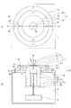
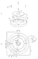
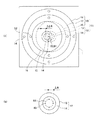
本発明のX線発生装置の一実施形態の構成を模式的に示す図である。It is a figure which shows typically the structure of one Embodiment of the X-ray generator of this invention. 図1中の陽極の構成と間隔調整部材の移動前後の状態を示す図である。It is a figure which shows the structure of the anode in FIG. 1, and the state before and behind the movement of a space | interval adjustment member. 本発明のX線発生装置の他の実施形態の構成を模式的に示す図である。It is a figure which shows typically the structure of other embodiment of the X-ray generator of this invention. 図3中の間隔調整部材の移動前後の状態と電子線の焦点の移動軌跡を示す図である。It is a figure which shows the state before and behind the movement of the space | interval adjustment member in FIG. 3, and the movement locus | trajectory of the focus of an electron beam. 本発明のX線発生装置の他の実施形態の構成を模式的に示す図である。It is a figure which shows typically the structure of other embodiment of the X-ray generator of this invention. 図5のX線発生装置のターゲット周辺の部分拡大図である。FIG. 6 is a partially enlarged view around a target of the X-ray generation apparatus of FIG. 5. 本発明のX線撮影システムの構成を模式的に示す図である。It is a figure which shows typically the structure of the X-ray imaging system of this invention.

以下、図面を参照しながら本発明を実施するための形態について説明する。これらの実施形態に記載されている構成部材の寸法、材質、形状、その相対配置などは、本発明の範囲を限定するものではない。尚、本明細書で特に図示又は記載されない部分に関しては、当該技術分野の周知又は公知技術を適用する。   DESCRIPTION OF EMBODIMENTS Hereinafter, embodiments for carrying out the present invention will be described with reference to the drawings. The dimensions, materials, shapes, and relative arrangements of the constituent members described in these embodiments do not limit the scope of the present invention. In addition, the well-known or well-known technique of the said technical field is applied regarding the part which is not illustrated or described in particular in this specification.

(実施形態1)
図1は本発明のX線発生装置の第1の実施形態の構成を模式的に示した図であり、(a)は平面図、(b)は(a)中のA−A’断面図である。図1(b)に示されるように、本発明のX線発生装置は、透過型のX線発生管10と、該X線発生管10を収納した収納容器1とを有している。収納容器1は金属筐体であり、内部には、X線発生管10を駆動するための駆動回路6が内蔵されていてもよい。本発明に係るX線発生管10は、陽極11と、陰極31と、絶縁管42とを備えている。尚、本発明において、管側陽極フランジ16、透過型ターゲット12、間隔調整部材17などの陽極11を構成する部材の「裏面」とは、後述する絶縁管42の管軸60に平行な方向において、陰極31側に位置する面を指す。また、「表面」とは、絶縁管42の管軸方向において、収納容器1の外側に位置する面を指す。
(Embodiment 1)
FIG. 1 is a diagram schematically showing a configuration of a first embodiment of an X-ray generator of the present invention, where (a) is a plan view, and (b) is a cross-sectional view taken along line AA ′ in (a). It is. As shown in FIG. 1B, the X-ray generator of the present invention has a transmission type X-ray generation tube 10 and a storage container 1 that stores the X-ray generation tube 10. The storage container 1 is a metal housing, and a drive circuit 6 for driving the X-ray generation tube 10 may be incorporated therein. The X-ray generator tube 10 according to the present invention includes an anode 11, a cathode 31, and an insulating tube 42. In the present invention, the “back surface” of the members constituting the anode 11 such as the tube side anode flange 16, the transmission type target 12, and the interval adjusting member 17 is in a direction parallel to the tube axis 60 of the insulating tube 42 described later. The surface located in the cathode 31 side is pointed out. The “surface” refers to a surface located outside the storage container 1 in the tube axis direction of the insulating tube 42.

収納容器1は導電性であり、鉄、ステンレス、鉛、真鍮、銅等の金属から構成され、通常は接地電位に規定されている。また、収納容器1内の余空間には、絶縁性流体2が充填されていても良い。絶縁性流体2としては、放射線発生管10の冷却及び、電気絶縁を行うため、冷却能力が高く、電気絶縁性の高いものが良く、また、透過型ターゲット12が発熱により高温になり、その熱が絶縁性流体2に伝わるため、熱による変質の少ないものが好ましい。よって絶縁性流体2としては、電気絶縁油、フッ素系の絶縁油等の絶縁性液体が使用可能である。   The storage container 1 is electrically conductive and is made of a metal such as iron, stainless steel, lead, brass, or copper, and is usually regulated to a ground potential. Further, the extra space in the storage container 1 may be filled with the insulating fluid 2. As the insulating fluid 2, since the radiation generating tube 10 is cooled and electrically insulated, it is preferable to have a high cooling capacity and a high electrical insulating property, and the transmissive target 12 becomes hot due to heat generation. Is transmitted to the insulating fluid 2, so that it is less likely to be altered by heat. Therefore, as the insulating fluid 2, an insulating liquid such as an electric insulating oil or a fluorine-based insulating oil can be used.

本例の絶縁管42はセラミックなどの絶縁体で構成されており、容器側陽極フランジ18とは銀ろう付けなどにより気密接合されている。絶縁管42の管軸方向において、ターゲット膜14と電子放出源21とが対向するように、絶縁管42の一端に陽極部材15が、他端に陰極部材32が、接続されている。   The insulating tube 42 of this example is made of an insulator such as ceramic and is hermetically joined to the container-side anode flange 18 by silver brazing or the like. In the tube axis direction of the insulating tube 42, the anode member 15 is connected to one end of the insulating tube 42 and the cathode member 32 is connected to the other end so that the target film 14 and the electron emission source 21 face each other.

本例の陽極11は、電子線7の照射によりX線8を発生する透過型ターゲット(以下、「ターゲットと記す」)12と、該ターゲット12に接続された陽極部材15とを有する。陽極部材15は、ターゲット12に接続される管側陽極フランジ16と、収納容器1に接続される容器側陽極フランジ18と、管側陽極フランジ16と容器側陽極フランジ18との間に配置される間隔調整部材17とを有している。陽極部材15はさらに、管側陽極フランジ16と容器側陽極フランジ18とが管軸方向の一端と他端とにおいて接続される可撓性陽極管51を備えている。管側陽極フランジ16は、ターゲット12をその周縁部で保持し、間隔調整部材17は管側陽極フランジ16をその周縁部で保持する。本例において、管側陽極フランジ16と間隔調整部材17とは互いに固定されていても、固定されていなくても良い。   The anode 11 of this example includes a transmission type target (hereinafter referred to as “target”) 12 that generates X-rays 8 when irradiated with an electron beam 7, and an anode member 15 connected to the target 12. The anode member 15 is disposed between the tube side anode flange 16 connected to the target 12, the container side anode flange 18 connected to the storage container 1, and the tube side anode flange 16 and the container side anode flange 18. And an interval adjusting member 17. The anode member 15 further includes a flexible anode tube 51 to which the tube side anode flange 16 and the container side anode flange 18 are connected at one end and the other end in the tube axis direction. The tube-side anode flange 16 holds the target 12 at its peripheral edge, and the interval adjusting member 17 holds the tube-side anode flange 16 at its peripheral edge. In this example, the tube side anode flange 16 and the interval adjusting member 17 may or may not be fixed to each other.

図2(a)は図1のX線発生装置の陽極11の構成を模式的に示す図であって、間隔調整部材17と管側陽極フランジ16とを離した状態を示す斜視図であり、可撓性陽極管51及び容器側陽極フランジ18は便宜上省略する。図2(a)に示されるように、間隔調整部材17は全体が円筒形状であり、表面側に管側陽極フランジ16を保持するための凹部が形成されている。凹部の内径は、管側陽極フランジ16の外径よりも若干大きく、凹部に嵌合された管側陽極フランジ16は、裏面の周縁部が凹部の底面17aに、外周が凹部の側面17bにそれぞれ接して間隔調整部材17に保持される。X線発生管10の内部は真空であるため、管側陽極フランジ16が間隔調整部材17に固定されていなくても、外部の大気圧との気圧差により、管側陽極フランジ16は間隔調整部材17の凹部の底面17aに常時突き当たり、締結される。間隔調整部材17は、絶縁管42の半径方向における可撓性陽極管51の外側に配置され、容器側陽極フランジ18に締結されるが、該間隔調整部材17は、係る締結を解除することで移動可能である。可撓性陽極管51については後述する。管側陽極フランジ16及び間隔調整部材17の材質としては、X線放射時にターゲット12で発生する熱を収納容器1に放熱しやすい高熱伝導率の材質が好ましく、例えば銅、タングステン、銅タングステン合金などが好ましく用いられる。また、容器側陽極フランジ18としては、セラミックで構成された絶縁管42と線膨脹係数が近い金属が好ましく、コバールなどが良い。   2 (a) is a diagram schematically showing the configuration of the anode 11 of the X-ray generator of FIG. 1, and is a perspective view showing a state in which the interval adjusting member 17 and the tube side anode flange 16 are separated from each other, The flexible anode tube 51 and the container side anode flange 18 are omitted for convenience. As shown in FIG. 2A, the interval adjusting member 17 has a cylindrical shape as a whole, and a recess for holding the tube-side anode flange 16 is formed on the surface side. The inner diameter of the recess is slightly larger than the outer diameter of the tube-side anode flange 16, and the tube-side anode flange 16 fitted into the recess has a peripheral edge on the back surface on the bottom surface 17a of the recess and an outer periphery on the side surface 17b of the recess. The distance adjusting member 17 is held in contact therewith. Since the inside of the X-ray generation tube 10 is vacuum, even if the tube side anode flange 16 is not fixed to the space adjustment member 17, the tube side anode flange 16 is separated from the external atmospheric pressure by the difference in atmospheric pressure. It always abuts against the bottom surface 17a of the concave portion 17 and is fastened. The interval adjusting member 17 is disposed outside the flexible anode tube 51 in the radial direction of the insulating tube 42 and is fastened to the container-side anode flange 18, and the interval adjusting member 17 releases the fastening. It is movable. The flexible anode tube 51 will be described later. The material of the tube side anode flange 16 and the interval adjusting member 17 is preferably a material having high thermal conductivity that can easily dissipate heat generated in the target 12 during X-ray emission to the storage container 1, for example, copper, tungsten, copper tungsten alloy, or the like. Is preferably used. The container-side anode flange 18 is preferably made of a metal having a linear expansion coefficient close to that of the insulating tube 42 made of ceramic, such as Kovar.

本例のターゲット12は、ターゲット基板13の裏面に電子線7の照射によってX線8を発生するターゲット膜14が形成される。そして、ターゲット基板13の裏面の周縁部及び外周が管側陽極フランジ16に銀ろう付けなどにより気密接合される。ターゲット基板13はX線8が透過しやすい材質からなり、例えばダイヤモンド、ベリリウムなどが好ましく、ターゲット膜14としては、タングステンなどが好ましく用いられる。   In the target 12 of this example, a target film 14 that generates X-rays 8 by irradiation of the electron beam 7 is formed on the back surface of the target substrate 13. And the peripheral part and outer periphery of the back surface of the target board | substrate 13 are airtightly joined to the pipe side anode flange 16 by silver brazing. The target substrate 13 is made of a material that allows easy transmission of X-rays 8. For example, diamond or beryllium is preferable. As the target film 14, tungsten or the like is preferably used.

陰極31は、ターゲット12に電子線7を放出する電子放出源21と、該電子放出源21に接続された陰極部材32とを有している。本例の電子放出源21は、熱フィラメント22と陰極支柱23とを有する電子銃であり、フィラメント22には駆動用端子24が接続され、陰極部材32の中央部に配置された絶縁部材33を通って外部に引き出されている。陰極部材32は絶縁管42の他端に溶接等により気密接合されている。   The cathode 31 includes an electron emission source 21 that emits the electron beam 7 to the target 12, and a cathode member 32 connected to the electron emission source 21. The electron emission source 21 of this example is an electron gun having a heat filament 22 and a cathode support 23, and a drive terminal 24 is connected to the filament 22, and an insulating member 33 disposed at the center of the cathode member 32 is provided. It is pulled out through. The cathode member 32 is hermetically joined to the other end of the insulating tube 42 by welding or the like.

X線発生管10は、容器側陽極フランジ18が接続された一端側が収納容器1の開口部3に固定される。よって、収納容器1の開口部3の穴径は、X線発生管10の絶縁管42の外径よりも大きい。本例においては、容器側陽極フランジ18が収納容器1の外側において開口部3の周縁に重なり、容器側陽極フランジ18と収納容器1とが互いにネジ54によって固定されている。尚、ネジ54で固定するために収納容器1に設けたネジ穴56と収納容器1の開口部3との間には、収納容器1の外面に対して内側に凹んだ溝(不図示)が形成され、係る溝にシール部材(不図示)が配置される。係る構成において、絶縁性流体2を充填した収納容器1内にX線発生管10を陰極31側から差し込み、絶縁管42の容器側陽極フランジ18を収納容器1に固定することで収納容器1が密閉され、X線発生管10が収納容器1に固定される。本発明では、陽極11が収納容器1の外側に配置され、後述するように、装置の外側から接触することができる。   One end side of the X-ray generation tube 10 to which the container side anode flange 18 is connected is fixed to the opening 3 of the storage container 1. Therefore, the hole diameter of the opening 3 of the storage container 1 is larger than the outer diameter of the insulating tube 42 of the X-ray generation tube 10. In this example, the container-side anode flange 18 overlaps the periphery of the opening 3 on the outside of the storage container 1, and the container-side anode flange 18 and the storage container 1 are fixed to each other by screws 54. A groove (not shown) recessed inward with respect to the outer surface of the storage container 1 is formed between the screw hole 56 provided in the storage container 1 for fixing with the screw 54 and the opening 3 of the storage container 1. A seal member (not shown) is formed in the groove. In such a configuration, the X-ray generator tube 10 is inserted into the storage container 1 filled with the insulating fluid 2 from the cathode 31 side, and the container-side anode flange 18 of the insulating tube 42 is fixed to the storage container 1 so that the storage container 1 is The X-ray generation tube 10 is sealed and fixed to the storage container 1. In this invention, the anode 11 is arrange | positioned on the outer side of the storage container 1, and it can contact from the outer side of an apparatus so that it may mention later.

本発明においては、管側陽極フランジ16と容器側陽極フランジ18とが、環状の可撓性陽極管51によって接続され、該可撓性陽極管51は管側陽極フランジ16と容器側陽極フランジ18とにろう付けや溶接などで気密接合されている。可撓性陽極管51としては、ステンレス製や銅製のベローズが好ましく用いられる。可撓性陽極管51が可撓性を有するため、X線発生管10内の気密を保持したまま、収納容器1と一体化された絶縁管42及び陰極31に対して、管側陽極フランジ16の位置を管軸60に平行な方向及び交差する方向のいずれにも変更可能である。但し、可撓性陽極管51の負担軽減のためには、管側陽極フランジ16の移動は管軸60に交差する面内での直線移動が好ましい。また、管側陽極フランジ16を管軸60に直交する面に対して傾斜して配置すれば、管軸60に直交する面に対して傾斜した面内で管側陽極フランジ16を移動させることができる。また、管側陽極フランジ16を管軸60に対して直交して配置すれば、管軸60に直交する面内で管側陽極フランジ16を移動させることができる。   In the present invention, the tube side anode flange 16 and the container side anode flange 18 are connected by an annular flexible anode tube 51, and the flexible anode tube 51 is connected to the tube side anode flange 16 and the container side anode flange 18. It is hermetically joined by brazing or welding. As the flexible anode tube 51, a stainless steel or copper bellows is preferably used. Since the flexible anode tube 51 has flexibility, the tube-side anode flange 16 is opposed to the insulating tube 42 and the cathode 31 integrated with the storage container 1 while maintaining the airtightness in the X-ray generation tube 10. This position can be changed to either a direction parallel to the tube axis 60 or a direction intersecting with the tube axis 60. However, in order to reduce the burden on the flexible anode tube 51, it is preferable that the tube-side anode flange 16 is moved linearly in a plane intersecting the tube axis 60. Further, if the tube-side anode flange 16 is disposed so as to be inclined with respect to a surface orthogonal to the tube axis 60, the tube-side anode flange 16 can be moved within a surface inclined with respect to the surface orthogonal to the tube axis 60. it can. Further, if the tube side anode flange 16 is arranged orthogonal to the tube axis 60, the tube side anode flange 16 can be moved in a plane orthogonal to the tube axis 60.

本例においては、図1、図2(a)に示すように、間隔調整部材17を容器側陽極フランジ18に締結するためのネジ52を貫通させるネジ穴53の平面形状が長穴であり、間隔調整部材17は係るネジ穴53を複数有している(本例では4個)。また、複数のネジ穴53は、長穴が同一方向を向いている。即ち、管軸60に直交する面内において、複数のネジ穴53の長軸が全て平行に配置されている。これに対して、容器側陽極フランジ18に設けたネジ穴55はネジ52に対応する通常の円形とし、ネジ52の位置を容器側陽極フランジ18に設けたネジ穴55によって所定の位置に固定する。これにより、ネジ穴53に貫通させるネジ52の、ネジ穴53内での位置をずらすことで、絶縁管42に対する間隔調整部材17の位置をネジ穴53の長軸方向にずらすことができる。   In this example, as shown in FIGS. 1 and 2 (a), the planar shape of the screw hole 53 through which the screw 52 for fastening the interval adjusting member 17 to the container side anode flange 18 is a long hole, The interval adjusting member 17 has a plurality of screw holes 53 (four in this example). Further, the plurality of screw holes 53 have the long holes facing the same direction. That is, the long axes of the plurality of screw holes 53 are all arranged in parallel within a plane orthogonal to the tube axis 60. On the other hand, the screw hole 55 provided in the container-side anode flange 18 is a normal circle corresponding to the screw 52, and the position of the screw 52 is fixed at a predetermined position by the screw hole 55 provided in the container-side anode flange 18. . Thereby, the position of the gap adjusting member 17 with respect to the insulating tube 42 can be shifted in the major axis direction of the screw hole 53 by shifting the position of the screw 52 penetrating the screw hole 53 in the screw hole 53.

図2(b)は管側陽極フランジ16及び間隔調整部材17の移動前後の状態を示す平面図であり、ネジ穴53の長軸方向の両端部でそれぞれネジ52を固定した場合を重ねて表した図である。ネジ穴53の紙面右端にネジ52が位置するように固定した場合の間隔調整部材17、管側陽極フランジ16、ターゲット基板13、ターゲット膜14、ネジ穴53を実線で示す。また、ネジ穴53の紙面左端にネジ52が位置するように固定した場合の間隔調整部材17、管側陽極フランジ16、ターゲット基板13、ターゲット膜14、ネジ穴53を破線で示す。図2(b)に示すように、ネジ穴53を長穴とすることで、管側陽極フランジ16をネジ穴53の長軸方向、即ち管軸60に直交する方向(本例では図中の矢印Aの方向)に最長でΔL直線移動させることができる。その結果、ターゲット膜14上の電子線7の焦点を最長でΔL移動させることができ、ターゲット膜14を広範囲に使用することができる。尚、本例では、管側陽極フランジ16と間隔調整部材17とを一体で直線移動させるため、管側陽極フランジ16と間隔調整部材17とを一体としてもよい。   FIG. 2B is a plan view showing the state before and after the movement of the tube side anode flange 16 and the interval adjusting member 17, and shows the case where the screws 52 are fixed at both ends in the major axis direction of the screw holes 53. FIG. The space adjusting member 17, the tube-side anode flange 16, the target substrate 13, the target film 14, and the screw hole 53 when the screw 52 is fixed so that the screw 52 is positioned at the right end of the screw hole 53 are shown by solid lines. In addition, the gap adjusting member 17, the tube-side anode flange 16, the target substrate 13, the target film 14, and the screw hole 53 when the screw 52 is fixed so that the screw 52 is positioned at the left end of the paper surface are indicated by broken lines. As shown in FIG. 2B, by making the screw hole 53 into a long hole, the tube side anode flange 16 is moved in the direction of the long axis of the screw hole 53, that is, in the direction perpendicular to the tube axis 60 (in this example, It is possible to make a linear movement of ΔL at the longest in the direction of arrow A). As a result, the focal point of the electron beam 7 on the target film 14 can be moved by ΔL at the longest, and the target film 14 can be used in a wide range. In this example, since the tube-side anode flange 16 and the interval adjusting member 17 are linearly moved together, the tube-side anode flange 16 and the interval adjusting member 17 may be integrated.

また、本例においては、間隔調整部材17を移動させる際に移動方向、さらには移動範囲を制御するガイド手段を設けてもよい。ガイド手段としては、間隔調整部材17が、本来移動する方向に対して交差する方向に移動しないように移動方向を制御する手段、さらには、間隔調整部材17の移動範囲の両端を制御する手段を設ければよい。具体的には、移動前後で間隔調整部材17が容器側陽極フランジ18に重なる領域を凹部として容器側陽極フランジ18に設け、該凹部内に間隔調整部材17を移動可能に配置させる。係る構成では、間隔調整部材17の移動が、本来の移動範囲内に制御される。よって、ネジ52をネジ穴53から抜き取って間隔調整部材17が自由に移動できる状態となっても、間隔調整部材17の移動範囲内でネジ穴53内からネジ穴55が外れることがなく、再びネジ52をネジ穴53,55に留めることが容易になる。また、間隔調整部材17の裏面に移動方向に平行な溝を設け、容器側陽極フランジ18の表面に該溝に移動可能に緩挿される凸部を設けておくことで、間隔調整部材17が本来の移動方向から交差する方向に移動するのが防止される。また、溝の長さを、間隔調整部材17の最大移動距離に対応させておけば、間隔調整部材17の移動が、本来の移動範囲内に制御され、ネジ52をネジ穴53,55から外しても、再びネジ52をネジ穴53,55に留めることが容易になる。尚、溝を容器側陽極フランジ18に、凸部を間隔調整部材17に設けても同様の効果が得られる。さらに、間隔調整部材17の周囲に、移動方向に沿った壁部を設けておくことで、間隔調整部材17が本来の移動方向から交差する方向に移動することが防止される。また、係る構成において、さらに、間隔調整部材17の移動範囲の両端に対応する壁部を設けておけば、間隔調整部材17の移動が、本来の移動範囲内に制御され、ネジ52をネジ穴53から外しても、再びネジ52をネジ穴53,55に留めることが容易になる。これら壁部は連続していても、柱状の壁部を移動方向に沿って配置しても良い。   Moreover, in this example, when moving the space | interval adjustment member 17, you may provide the guide means which controls a moving direction and also a moving range. As the guide means, means for controlling the moving direction so that the distance adjusting member 17 does not move in a direction crossing the original moving direction, and means for controlling both ends of the moving range of the distance adjusting member 17. What is necessary is just to provide. Specifically, a region in which the interval adjusting member 17 overlaps the container side anode flange 18 before and after the movement is provided as a recess in the container side anode flange 18, and the interval adjusting member 17 is movably disposed in the recess. In such a configuration, the movement of the interval adjusting member 17 is controlled within the original movement range. Therefore, even if the screw 52 is removed from the screw hole 53 and the distance adjusting member 17 can move freely, the screw hole 55 does not come out of the screw hole 53 within the moving range of the distance adjusting member 17, and again. It becomes easy to fasten the screw 52 to the screw holes 53 and 55. Further, by providing a groove parallel to the moving direction on the back surface of the gap adjusting member 17 and providing a convex part on the surface of the container side anode flange 18 that is loosely inserted into the groove, the gap adjusting member 17 is originally It is prevented from moving in the crossing direction from the moving direction. Further, if the length of the groove is made to correspond to the maximum moving distance of the interval adjusting member 17, the movement of the interval adjusting member 17 is controlled within the original moving range, and the screw 52 is removed from the screw holes 53 and 55. However, it becomes easy to fasten the screw 52 in the screw holes 53 and 55 again. The same effect can be obtained by providing the groove on the container-side anode flange 18 and the convex portion on the interval adjusting member 17. Furthermore, by providing a wall portion along the moving direction around the interval adjusting member 17, the interval adjusting member 17 is prevented from moving in a direction intersecting with the original moving direction. In this configuration, if walls corresponding to both ends of the movement range of the distance adjusting member 17 are further provided, the movement of the distance adjusting member 17 is controlled within the original movement range, and the screw 52 is screwed into the screw hole. Even if it removes from 53, it becomes easy to fasten the screw | thread 52 to the screw holes 53 and 55 again. These wall portions may be continuous, or columnar wall portions may be arranged along the moving direction.

本例では、ネジ52を緩めて間隔調整部材17と容器側陽極フランジ18との締結を解除し、管側陽極フランジ16をネジ穴53の長軸方向にずらした後、ネジ52を締め直して締結する工程により、ターゲット膜14上の電子線の焦点をずらすことができる。よって、係る工程を定期的に行うことで、ターゲット膜14上の電子線の焦点を定期的に移動させて発熱によるダメージを回避し、ターゲット膜14の寿命を延ばすことができる。また、間隔調整部材16を移動させる際に、容器側陽極フランジ18との間に隙間があいても、管側陽極フランジ16が可撓性陽極管51を介して絶縁管42に気密固定されているため、移動時にX線発生管10の気密性が低下するおそれがない。よって、係る工程は、装置の使用者が手動で容易に行うことができる。   In this example, the screw 52 is loosened to release the fastening between the interval adjusting member 17 and the container-side anode flange 18, the tube-side anode flange 16 is shifted in the long axis direction of the screw hole 53, and then the screw 52 is retightened. The focus of the electron beam on the target film 14 can be shifted by the fastening process. Therefore, by periodically performing such a process, the focal point of the electron beam on the target film 14 can be periodically moved to avoid damage due to heat generation, and the life of the target film 14 can be extended. Further, when moving the distance adjusting member 16, the tube-side anode flange 16 is hermetically fixed to the insulating tube 42 via the flexible anode tube 51 even if there is a gap with the container-side anode flange 18. Therefore, there is no possibility that the airtightness of the X-ray generating tube 10 is lowered during movement. Therefore, the process can be easily performed manually by the user of the apparatus.

(実施形態2)
上記実施形態1では、管側陽極フランジ16を管軸60に交差する方向に直線移動させたが、本実施形態では、管側陽極フランジ16に対して間隔調整部材17を回転移動させて、ターゲット膜14上の電子線7の焦点を回転移動させることに特徴を有する。以下、本例について、実施形態1と異なる構成、作用についてのみ説明する。図3は本例のX線発生装置全体の構成を模式的に示した図であり、(a)は平面図、(b)は(a)中のA−A’断面図である。
(Embodiment 2)
In the first embodiment, the tube-side anode flange 16 is linearly moved in the direction intersecting the tube axis 60. However, in the present embodiment, the interval adjusting member 17 is rotationally moved with respect to the tube-side anode flange 16, and the target is moved. It is characterized in that the focal point of the electron beam 7 on the film 14 is rotated. Hereinafter, only the configuration and operation different from the first embodiment will be described in this example. 3A and 3B are diagrams schematically showing the overall configuration of the X-ray generator of this example, in which FIG. 3A is a plan view and FIG. 3B is a cross-sectional view taken along line AA ′ in FIG.

本例においても、実施形態1と同様に陽極11を透過型のターゲット12と陽極部材15とで構成する。本例においても、陽極部材15は、管側陽極フランジ16と間隔調整部材17と容器側陽極フランジ18と、管側陽極フランジ16と容器側陽極フランジ18とに気密接合された可撓性陽極管51とを有する。また、可撓性陽極管51の外側において間隔調整部材17は容器側陽極フランジ18に締結される。また、本例においては、X線発生管10内の気圧と外部の大気圧との気圧差によって、管側陽極フランジ16は間隔調整部材17に強く押圧されて互いに締結されているが、互いに固定されてはいない。よって、後述するように、間隔調整部材17は管側陽極フランジ16に対して回転移動可能である。そして本例では、図3(a)、(b)に示されるように、間隔調整部材17の中心軸61を管軸60に一致させ、管側陽極フランジ16の中心軸62を間隔調整部材17の中心軸61及び管軸60から、管軸60に直交する方向にΔRずらす構成とした。   Also in this example, the anode 11 is composed of the transmission type target 12 and the anode member 15 as in the first embodiment. Also in this example, the anode member 15 is a flexible anode tube hermetically bonded to the tube side anode flange 16, the interval adjusting member 17, the container side anode flange 18, and the tube side anode flange 16 and the container side anode flange 18. 51. In addition, the interval adjusting member 17 is fastened to the container-side anode flange 18 outside the flexible anode tube 51. Further, in this example, the tube-side anode flange 16 is strongly pressed by the interval adjusting member 17 and fastened to each other due to the difference in pressure between the pressure inside the X-ray generation tube 10 and the external atmospheric pressure, but is fixed to each other. It has not been done. Therefore, as will be described later, the interval adjusting member 17 can be rotated with respect to the tube-side anode flange 16. In this example, as shown in FIGS. 3A and 3B, the center axis 61 of the interval adjusting member 17 is made to coincide with the tube axis 60, and the center axis 62 of the tube side anode flange 16 is set to the interval adjusting member 17. The center axis 61 and the tube axis 60 are shifted by ΔR in a direction perpendicular to the tube axis 60.

上記構成で、間隔調整部材17の容器側陽極フランジ18との締結を解除し、中心軸61を中心に間隔調整部材17を回転させる。可撓性陽極管51を介して容器側陽極フランジ18に接続された管側陽極フランジ16は、間隔調整部材17の回転に追随できない。その結果、管側陽極フランジ16の間隔調整部材17と接する裏面の周縁部と外周とが間隔調整部材17の凹部の底面と側面に対して摺動する。この時、間隔調整部材17は回転しても容器側陽極フランジ18に重なる領域は変動しないが、管側陽極フランジ16の中心軸62が間隔調整部材17の中心軸61からずれているため、管側陽極フランジ16の容器側陽極フランジ18に重なる領域が変動する。即ち、管側陽極フランジ16は、管軸60に直交する面内において、向きを変えないまま、中心軸61,62間の距離ΔRを半径とする回転移動を行う。管側陽極フランジ16は可撓性陽極管51を介して容器側陽極フランジ18に接続されているが、ΔRを半径とする回転移動による管側陽極フランジ16の可撓性陽極管51との接合部位の位置の変動は小さい。また、可撓性陽極管51が可撓性を有するため、係る変動によっても、可撓性陽極管51を介した容器側陽極フランジ18との気密接合は保持される。このように、間隔調整部材17の回転によって、管側陽極フランジ16がΔRを半径とする回転移動を行うと、管側陽極フランジ16に保持されたターゲット膜14上で電子線7の焦点位置がΔRを半径とする回転移動を行うことになる。   With the above-described configuration, the fastening of the spacing adjusting member 17 with the container side anode flange 18 is released, and the spacing adjusting member 17 is rotated about the central axis 61. The tube-side anode flange 16 connected to the container-side anode flange 18 via the flexible anode tube 51 cannot follow the rotation of the interval adjusting member 17. As a result, the peripheral edge portion and the outer periphery of the back surface of the tube side anode flange 16 in contact with the interval adjusting member 17 slide against the bottom surface and the side surface of the recess of the interval adjusting member 17. At this time, even if the interval adjusting member 17 is rotated, the region overlapping the container side anode flange 18 does not change, but the center axis 62 of the tube side anode flange 16 is deviated from the center axis 61 of the interval adjusting member 17. The region of the side anode flange 16 overlapping the container side anode flange 18 varies. That is, the tube-side anode flange 16 rotates in a plane orthogonal to the tube axis 60 with the distance ΔR between the central shafts 61 and 62 as a radius without changing the orientation. The tube-side anode flange 16 is connected to the container-side anode flange 18 via the flexible anode tube 51, but the tube-side anode flange 16 is joined to the flexible anode tube 51 by a rotational movement with a radius of ΔR. The variation of the position of the part is small. Moreover, since the flexible anode tube 51 has flexibility, the airtight joining with the container side anode flange 18 through the flexible anode tube 51 is maintained even by such fluctuation. As described above, when the tube-side anode flange 16 is rotated with the radius ΔR by the rotation of the interval adjusting member 17, the focal position of the electron beam 7 on the target film 14 held by the tube-side anode flange 16 is changed. A rotational movement with a radius of ΔR is performed.

本例において、間隔調整部材17を中心軸61を中心に180°回転させた前後の状態を図4(a)に示す。図4(a)において、回転前の管側陽極フランジ16、ターゲット基板13、ターゲット膜14を実線で、回転後の管側陽極フランジ16、ターゲット基板13、ターゲット膜14を破線で示す。図4(a)に示されるように、間隔調整部材17は中心軸61を中心に回転するため、180°回転しても容器側陽極フランジ18に重なる領域は変動しない。一方、管側陽極フランジ16は中心軸62が回転の中心軸61からずれているため、間隔調整部材17が180°回転すると、管側陽極フランジ16はターゲット12と共に向きを変えずに管軸60に直交する方向に2ΔR移動する。その結果、電子線7の焦点位置がターゲット膜14上で管軸60に直交する方向に2ΔR移動する。図4(b)は間隔調整部材17を360°回転させた場合の、電子線7の焦点63のターゲット膜14上での軌跡64を示した部分拡大平面図である。図4(b)では、電子線7が管軸60に一致している場合を示す。間隔調整部材17の回転によって、ターゲット膜14上で電子線7の焦点63は中心軸61,62間の距離ΔRを半径とする回転移動することになる。ΔRを0.05mとすれば、ターゲット膜14上で電子線7の焦点を最大で0.1mm移動させることができる。   FIG. 4A shows a state before and after the interval adjusting member 17 is rotated by 180 ° around the central axis 61 in this example. In FIG. 4A, the tube side anode flange 16, the target substrate 13 and the target film 14 before rotation are indicated by solid lines, and the tube side anode flange 16, the target substrate 13 and the target film 14 after rotation are indicated by broken lines. As shown in FIG. 4A, since the interval adjusting member 17 rotates about the central axis 61, the region overlapping the container-side anode flange 18 does not change even if rotated 180 °. On the other hand, since the center axis 62 of the tube side anode flange 16 is deviated from the rotation center shaft 61, when the interval adjusting member 17 rotates 180 °, the tube side anode flange 16 does not change its orientation together with the target 12. It moves 2ΔR in the direction orthogonal to As a result, the focal position of the electron beam 7 moves 2ΔR in the direction perpendicular to the tube axis 60 on the target film 14. FIG. 4B is a partially enlarged plan view showing a locus 64 on the target film 14 of the focal point 63 of the electron beam 7 when the interval adjusting member 17 is rotated 360 °. FIG. 4B shows a case where the electron beam 7 coincides with the tube axis 60. As the distance adjusting member 17 rotates, the focal point 63 of the electron beam 7 rotates on the target film 14 with the distance ΔR between the central axes 61 and 62 as a radius. If ΔR is 0.05 m, the focal point of the electron beam 7 can be moved by 0.1 mm at the maximum on the target film 14.

本例では、間隔調整部材17の容器側陽極フランジ18との締結を解除し、間隔調整部材17を中心軸61を中心として回転させた後、再び容器側陽極フランジ18に締結する工程により、ターゲット膜14上で電子線7の焦点63を移動させることができる。よって、係る工程を定期的に行うことで、ターゲット膜14上の電子線7の焦点63を定期的に移動させて発熱によるダメージを回避し、ターゲット膜14の寿命を延ばすことができる。また、間隔調整部材16を移動させる際に、容器側陽極フランジ18との間に隙間があいても、管側陽極フランジ16が可撓性陽極管51を介して容器側陽極フランジ18に気密に接続されているため、移動時にX線発生管10の気密性が低下するおそれがない。よって、係る工程は、装置の使用者が手動で容易に行うことができる。   In this example, the fastening of the gap adjusting member 17 with the container side anode flange 18 is released, the gap adjusting member 17 is rotated about the central axis 61, and then fastened to the container side anode flange 18 again. The focal point 63 of the electron beam 7 can be moved on the film 14. Therefore, by periodically performing such a process, the focal point 63 of the electron beam 7 on the target film 14 can be periodically moved to avoid damage due to heat generation, and the life of the target film 14 can be extended. Further, when the gap adjusting member 16 is moved, the tube-side anode flange 16 is hermetically sealed to the container-side anode flange 18 via the flexible anode tube 51 even if there is a gap between the interval-adjusting member 16 and the container-side anode flange 18. Since they are connected, there is no possibility that the airtightness of the X-ray generation tube 10 is lowered during movement. Therefore, the process can be easily performed manually by the user of the apparatus.

尚、本例では、間隔調整部材17のネジ52による締結箇所を4箇所としたため、間隔調整部材17の移動を3回行って、ターゲット膜14内の合計4箇所を使用することができる。本発明では、上記締結箇所を増やすことで、ターゲット膜14の使用箇所を増やすことができる。また、間隔調整部材17のネジ穴53を間隔調整部材17の外周形状に対応した弧状としたり、クランプなどの固定手段を用いたりすることで、ターゲット膜14をより広く使用することができる。   In this example, since the fastening positions of the spacing adjusting member 17 by the screws 52 are four, the spacing adjusting member 17 can be moved three times to use a total of four places in the target film 14. In this invention, the usage location of the target film | membrane 14 can be increased by increasing the said fastening location. Moreover, the target film | membrane 14 can be used more widely by making the screw hole 53 of the space | interval adjustment member 17 into the arc shape corresponding to the outer periphery shape of the space | interval adjustment member 17, or using fixing means, such as a clamp.

また、本例においては、間隔調整部材17が回転移動によって管軸60に交差する方向に移動して、間隔調整部材17が容器側陽極フランジ18に重なる領域が移動前よりずれるのを防止するガイド手段を設けても良い。具体的には、容器側陽極フランジ18の表面に、間隔調整部材17の外径よりも内径が若干大きい凹部を形成し、間隔調整部材17が該凹部内で回転可能なように、間隔調整部材17を該凹部に緩挿させればよい。また、容器側陽極フランジ18の表面に、管軸60を中心とする環状の溝を形成し、間隔調整部材17の裏面に、移動可能に該溝に緩挿される凸部を設けておいても良い。また、溝を間隔調整部材17に、凸部を容器側陽極フランジ18に設けても良い。さらに、管軸60を中心とし、間隔調整部材17が回転可能なように間隔調整部材17の外周より若干大きな直径の円形に沿った内壁を有する壁部を設けても良い。この場合、壁部は周方向に連続した環状でも、柱状の壁部を環状に配置したものでも、いずれでも良い。   Further, in this example, the gap adjusting member 17 is moved in the direction intersecting the tube axis 60 by the rotational movement, and the area where the gap adjusting member 17 overlaps the container side anode flange 18 is prevented from being shifted from before the movement. Means may be provided. Specifically, a gap adjusting member is formed on the surface of the container-side anode flange 18 so that a recess having an inner diameter slightly larger than the outer diameter of the gap adjusting member 17 is formed, and the gap adjusting member 17 is rotatable in the recess. What is necessary is just to loosely insert 17 in this recessed part. Alternatively, an annular groove centered on the tube shaft 60 may be formed on the surface of the container-side anode flange 18, and a convex portion that is movably loosely inserted into the groove may be provided on the back surface of the interval adjusting member 17. good. Further, the groove may be provided in the interval adjusting member 17 and the convex portion may be provided in the container side anode flange 18. Further, a wall portion having an inner wall along a circle having a diameter slightly larger than the outer periphery of the interval adjusting member 17 may be provided so that the interval adjusting member 17 can rotate around the tube shaft 60. In this case, the wall portion may be either a ring that is continuous in the circumferential direction or a columnar wall portion that is arranged in a ring shape.

本例では、間隔調整部材17を、中心軸61を中心に管側陽極フランジ16に対して回転させる形態を示したが、間隔調整部材17の回転中心を中心軸61からずらして回転移動させることもできる。具体的には、管側陽極フランジ16の中心軸62と間隔調整部材17の中心軸は一致させた状態で、間隔調整部材17の中心軸61を、管軸60に対してずらす。すると、管側陽極フランジ16は向きを変えずに上記仮想中心軸と管軸60との距離を半径とする回転移動を行い、ターゲット膜14上での電子線7の焦点63も、上記仮想中心軸と管軸60との距離を半径とする回転移動を行う。尚、この場合、間隔調整部材17は仮想中心軸を中心として回転しながら、その中心軸61も仮想中心軸と管軸60との距離を半径とする回転移動を行うため、回転前後で間隔調整部材17の容器側陽極フランジ18に重なる領域がずれる。即ち、間隔調整部材17の容器側陽極フランジ18への締結位置が変動する。従って、間隔調整部材17を容器側陽極フランジ18に締結するネジ穴55については、係る移動分を考慮して大きく形成しておくか、或いは、クランプ等、間隔調整部材17の位置に関わらず、締結できる手段に変更すればよい。また、本例において、間隔調整部材17の回転移動の際に、容器側陽極フランジ18に本来重なる領域からずれてしまうのを防止するためにガイド手段を設けて良い。具体的には、移動前後で間隔調整部材17が容器側陽極フランジ18に重なる領域を凹部として容器側陽極フランジ18に設け、該凹部内に間隔調整部材17を移動可能に配置させる。係る構成では、間隔調整部材17の移動が、本来の移動範囲内に制御される。或いは、容器側陽極フランジ18の表面に凸部を設け、間隔調整部材17の裏面に、間隔調整部材17が回転移動した際に、上記凸部が移動する位置に沿って該凸部が移動可能に緩挿される溝を設けておけば良い。この場合、間隔調整部材17に凸部を、容器側陽極フランジ18に溝を設けておいても良い。さらには、間隔調整部材17の移動範囲を囲む位置に内壁を有する壁部を設けても良い。この場合、壁部は周方向に連続した環状でも、柱状の壁部を環状に配置したものでも、いずれでも良い。   In this example, the interval adjusting member 17 is rotated with respect to the tube-side anode flange 16 about the central axis 61. However, the rotation center of the interval adjusting member 17 is shifted from the central axis 61 and rotated. You can also. Specifically, the center axis 61 of the interval adjusting member 17 is shifted with respect to the tube axis 60 while the center axis 62 of the tube side anode flange 16 and the center axis of the interval adjusting member 17 are aligned. Then, the tube-side anode flange 16 performs a rotational movement with the radius between the virtual center axis and the tube axis 60 without changing the orientation, and the focal point 63 of the electron beam 7 on the target film 14 also has the virtual center. A rotational movement is performed with the distance between the shaft and the tube shaft 60 as a radius. In this case, while the interval adjusting member 17 rotates about the virtual central axis, the central axis 61 also performs rotational movement with the distance between the virtual central axis and the tube axis 60 as the radius. The region overlapping the container side anode flange 18 of the member 17 is shifted. That is, the fastening position of the gap adjusting member 17 to the container side anode flange 18 varies. Therefore, the screw hole 55 for fastening the interval adjusting member 17 to the container-side anode flange 18 is formed large in consideration of such movement, or regardless of the position of the interval adjusting member 17 such as a clamp. What is necessary is just to change to the means which can be fastened. Further, in this example, a guide means may be provided in order to prevent the gap adjusting member 17 from being displaced from the region that originally overlaps the container side anode flange 18 when the interval adjusting member 17 is rotationally moved. Specifically, a region in which the interval adjusting member 17 overlaps the container side anode flange 18 before and after the movement is provided as a recess in the container side anode flange 18, and the interval adjusting member 17 is movably disposed in the recess. In such a configuration, the movement of the interval adjusting member 17 is controlled within the original movement range. Alternatively, a convex portion is provided on the surface of the container-side anode flange 18, and the convex portion can move along the position where the convex portion moves when the spacing adjusting member 17 rotates on the back surface of the spacing adjusting member 17. It is sufficient to provide a groove that is loosely inserted into the. In this case, a convex portion may be provided in the interval adjusting member 17 and a groove may be provided in the container side anode flange 18. Furthermore, you may provide the wall part which has an inner wall in the position surrounding the movement range of the space | interval adjustment member 17. FIG. In this case, the wall portion may be either a ring that is continuous in the circumferential direction or a columnar wall portion that is arranged in a ring shape.

(実施形態3)
上記実施形態2では、管側陽極フランジ16の中心軸62を間隔調整部材17の回転中心からずらせる形態を示したが、本実施形態では、管側陽極フランジ16の姿勢を傾けることに特徴を有する。以下、本例について、実施形態1、2と異なる構成、作用についてのみ説明する。図5は本例のX線発生装置の構成を模式的に示した図であり、(a)は平面図、(b)は(a)中のA−A’断面図である。また、図6(a)は図5(b)のターゲット12の周辺の部分拡大図であり、図6(b)は、図6(a)の状態から中心軸61を中心に間隔調整部材17を180°回転させた状態を示す図である。
(Embodiment 3)
In the second embodiment, the center axis 62 of the tube side anode flange 16 is shifted from the rotation center of the interval adjusting member 17. However, the present embodiment is characterized in that the posture of the tube side anode flange 16 is inclined. Have. Hereinafter, only the configuration and operation different from the first and second embodiments will be described in this example. 5A and 5B are diagrams schematically showing the configuration of the X-ray generator of this example, in which FIG. 5A is a plan view and FIG. 5B is a cross-sectional view taken along line AA ′ in FIG. FIG. 6A is a partially enlarged view of the periphery of the target 12 in FIG. 5B, and FIG. 6B shows the distance adjusting member 17 around the central axis 61 from the state of FIG. It is a figure which shows the state which rotated 180 degrees.

本例においても、実施形態1と同様に陽極11をターゲット12と陽極部材15とで構成する。そして、陽極部材15は、管側陽極フランジ16と間隔調整部材17と容器側陽極フランジ18と可撓性陽極管51で構成し、管側陽極フランジ16及び容器側陽極フランジ18に可撓性陽極管51を気密接合する。間隔調整部材17は可撓性陽極管51の外側において容器側陽極フランジ18に締結され、管側陽極フランジ16と間隔調整部材17とは互いに固定されていない。また、間隔調整部材17の中心軸61は管軸60と一致させる。そして本例では、図5(b)に示されるように、管側陽極フランジ16を管軸60に直交する面に対して傾斜させて間隔調整部材17に保持させる。具体的には、本例においては、間隔調整部材17が、管側陽極フランジ16を保持する凹部の底面(図2(a)における17a)が、周方向周りに高さ分布を有している。よって、本例においては、間隔調整部材17が管側陽極フランジ16と接する面と、間隔調整部材17が容器側陽極フランジ18と接する面とが、互いに非平行である。   Also in this example, the anode 11 is composed of the target 12 and the anode member 15 as in the first embodiment. The anode member 15 includes a tube side anode flange 16, a distance adjusting member 17, a container side anode flange 18, and a flexible anode tube 51, and the tube side anode flange 16 and the container side anode flange 18 have flexible anodes. The tube 51 is hermetically joined. The interval adjusting member 17 is fastened to the container side anode flange 18 outside the flexible anode tube 51, and the tube side anode flange 16 and the interval adjusting member 17 are not fixed to each other. Further, the central axis 61 of the interval adjusting member 17 is made to coincide with the tube axis 60. In this example, as shown in FIG. 5B, the tube side anode flange 16 is tilted with respect to a plane orthogonal to the tube axis 60 and is held by the interval adjusting member 17. Specifically, in this example, the interval adjusting member 17 has a bottom surface (17a in FIG. 2 (a)) of a recess that holds the tube-side anode flange 16 having a height distribution around the circumferential direction. . Therefore, in this example, the surface where the gap adjusting member 17 is in contact with the tube side anode flange 16 and the face where the gap adjusting member 17 is in contact with the container side anode flange 18 are not parallel to each other.

ここで、ターゲット12を管側陽極フランジ16の表面側に配置させた場合について説明する。この場合、管側陽極フランジ16の裏面の中心71を、間隔調整部材17の中心軸61及び管軸60と一致させる。管側陽極フランジ16の裏面の中心71を通るターゲット膜14の裏面の法線63は、ターゲット膜14の裏面、即ち電子入射面において、管軸60が通る位置73から離れた位置72を通る。ターゲット膜14が管側陽極フランジ16と同心円状に配置されていた場合、位置72はターゲット膜14の裏面の中心である。上記構成で間隔調整部材17と容器側陽極フランジ18との締結を解除し、間隔調整部材17を中心軸61を中心に回転させる。可撓性陽極管51を介して容器側陽極フランジ18に接続されている管側陽極フランジ16は係る回転に追随できず、係る回転に伴って中心軸61を中心に管側陽極フランジ16の傾斜方向が回転する。即ち間隔調整部材17は管側陽極フランジ16に対して回転し、管側陽極フランジ16及びターゲット12は揺動する。間隔調整部材17が180°回転した状態では、図6(b)に示されるように、管側陽極フランジ16が管軸60に直交する面に対して回転前とは逆方向に傾いた状態となる。図6(b)において、管側陽極フランジ16の裏面の中心71を通るターゲット膜14の裏面の法線63がターゲット膜14の裏面を通る位置72は、管軸60を中心に反対側に移動する。ターゲット膜14自体は図6(a)の状態から回転していないため、管軸60がターゲット膜14の裏面を通る位置は回転前の位置73から位置72を中心に反対側の位置73’に移動する。即ち、間隔調整部材17を回転させることでターゲット膜14が揺動し、管軸60に平行な方向から見ると、ターゲット膜14の裏面が位置72と管軸60との距離ΔTを半径とする回転移動を行う。管軸60に対して電子線7の焦点位置は一定(本例では電子線7が管軸60に一致)であるため、間隔調整部材17の回転に伴って、電子線7の焦点も位置72を中心として、ターゲット膜14上で位置72と管軸60との距離ΔSを半径とする回転移動を行う。   Here, the case where the target 12 is arranged on the surface side of the tube side anode flange 16 will be described. In this case, the center 71 of the back surface of the tube side anode flange 16 is made to coincide with the center axis 61 and the tube axis 60 of the interval adjusting member 17. The normal 63 on the back surface of the target film 14 passing through the center 71 on the back surface of the tube side anode flange 16 passes through a position 72 away from the position 73 through which the tube axis 60 passes on the back surface of the target film 14, that is, the electron incident surface. When the target film 14 is arranged concentrically with the tube side anode flange 16, the position 72 is the center of the back surface of the target film 14. With the above configuration, the fastening between the gap adjusting member 17 and the container-side anode flange 18 is released, and the gap adjusting member 17 is rotated about the central axis 61. The tube-side anode flange 16 connected to the container-side anode flange 18 via the flexible anode tube 51 cannot follow the rotation, and the tube-side anode flange 16 is inclined around the central axis 61 with the rotation. The direction rotates. That is, the interval adjusting member 17 rotates with respect to the tube side anode flange 16, and the tube side anode flange 16 and the target 12 swing. In the state where the interval adjusting member 17 is rotated by 180 °, as shown in FIG. 6B, the tube side anode flange 16 is inclined in the direction opposite to the direction before the rotation with respect to the plane orthogonal to the tube axis 60. Become. In FIG. 6B, the position 72 where the normal 63 on the back surface of the target film 14 passing through the back surface center 71 of the tube side anode flange 16 passes through the back surface of the target film 14 moves to the opposite side around the tube axis 60. To do. Since the target film 14 itself has not rotated from the state of FIG. 6A, the position where the tube axis 60 passes through the back surface of the target film 14 is changed from the position 73 before rotation to the position 73 ′ on the opposite side centering on the position 72. Moving. In other words, the target film 14 is swung by rotating the distance adjusting member 17, and when viewed from a direction parallel to the tube axis 60, the back surface of the target film 14 has a radius ΔT between the position 72 and the tube axis 60. Perform rotational movement. Since the focal position of the electron beam 7 is constant with respect to the tube axis 60 (in this example, the electron beam 7 coincides with the tube axis 60), the focal point of the electron beam 7 is also at the position 72 as the interval adjusting member 17 rotates. Is rotated on the target film 14 with the distance ΔS between the position 72 and the tube axis 60 as a radius.

本例において、間隔調整部材17を180°回転させた場合の、電子線7の焦点の移動量2ΔS、即ち、図6(b)におけるターゲット膜14上での位置73から73’までの距離は、以下の式で導き出される。   In this example, when the distance adjusting member 17 is rotated by 180 °, the movement amount 2ΔS of the focal point of the electron beam 7, that is, the distance from the position 73 to 73 ′ on the target film 14 in FIG. Is derived from the following equation.

2ΔS=W1×tanθ
ここで、θは管軸60に直交する方向に対する管側陽極フランジ16の傾斜角度であり、W1は管側陽極フランジ16の裏面からターゲット膜14の裏面までの距離である。ターゲット12が、管側陽極フランジ16の表面にターゲット基板13の表面が一致するように取り付けられている場合には、W1=W2−W3(W2は管側陽極フランジ16の厚さ、W3はターゲット基板13とターゲット膜14とを合わせた厚さ)である。尚、ターゲット基板13とターゲット膜14の厚さは管側陽極フランジ16の厚さに比較して小さいため、実質的にW1=W2で算出しても良い。
2ΔS = W1 × tan θ
Here, θ is the inclination angle of the tube side anode flange 16 with respect to the direction orthogonal to the tube axis 60, and W 1 is the distance from the back surface of the tube side anode flange 16 to the back surface of the target film 14. When the target 12 is mounted so that the surface of the target substrate 13 coincides with the surface of the tube side anode flange 16, W1 = W2−W3 (W2 is the thickness of the tube side anode flange 16 and W3 is the target. The total thickness of the substrate 13 and the target film 14). Since the thicknesses of the target substrate 13 and the target film 14 are smaller than the thickness of the tube-side anode flange 16, it may be calculated substantially as W1 = W2.

例えば、絶縁管42の外径内において、管側陽極フランジ16の裏面の管軸60方向の最大差を管側陽極フランジ16の傾斜量とする。そして、絶縁管42の外径を60mm、管側陽極フランジ16の傾斜量を1mm、管側陽極フランジ16の裏面からターゲット膜14までの距離W1=5mmとした時、tanθ=1/60であり、2ΔSは0.167mmとなる。よって、マイクロフォーカスX線発生装置において、ターゲット膜14上で電子線7の焦点を100μm以上移動させることができる。   For example, the maximum difference in the tube axis 60 direction on the back surface of the tube-side anode flange 16 within the outer diameter of the insulating tube 42 is defined as the amount of inclination of the tube-side anode flange 16. When the outer diameter of the insulating tube 42 is 60 mm, the amount of inclination of the tube side anode flange 16 is 1 mm, and the distance W1 from the back surface of the tube side anode flange 16 to the target film 14 is 5 mm, tan θ = 1/60. 2ΔS is 0.167 mm. Therefore, in the microfocus X-ray generator, the focal point of the electron beam 7 can be moved on the target film 14 by 100 μm or more.

可撓性陽極管51としてベローズを用いた場合、ベローズは管軸60に直交する方向よりも平行な方向に変形しやすい。よって、本例ではベローズを用いることで、間隔調整部材17の回転により、可撓性陽極管51が変形しやすい方向に管側陽極フランジ16を揺動させて、ターゲット膜14上の電子線7の焦点位置を移動させることができる。   When a bellows is used as the flexible anode tube 51, the bellows is likely to be deformed in a direction parallel to the direction perpendicular to the tube axis 60. Therefore, in this example, by using the bellows, the tube-side anode flange 16 is swung in the direction in which the flexible anode tube 51 is easily deformed by the rotation of the interval adjusting member 17, so that the electron beam 7 on the target film 14 is rotated. The focal position of can be moved.

また、本例では、管側陽極フランジ16の表面側にターゲット12を取り付けた形態を例に挙げて説明したが、管側陽極フランジ16の裏面側にターゲット12を取り付けた形態でも同様に構成することができる。この場合、管軸60と間隔調整部材の中心軸61と管側陽極フランジ16の表面の中心とを一致させればよい。   Moreover, in this example, although the form which attached the target 12 to the surface side of the tube side anode flange 16 was mentioned as an example, it comprised similarly with the form which attached the target 12 to the back surface side of the tube side anode flange 16. be able to. In this case, the tube shaft 60, the center axis 61 of the interval adjusting member, and the center of the surface of the tube-side anode flange 16 may be aligned.

また、本例においても、実施形態2と同様に、間隔調整部材17が回転移動によって管軸60に交差する方向に移動して、間隔調整部材17が容器側陽極フランジ18に重なる領域が移動前よりずれるのを防止するガイド手段を設けてもよい。具体的には、実施形態2と同様に、容器側陽極フランジ18の表面に、間隔調整部材17の外径よりも内径が若干大きい凹部を形成し、間隔調整部材17が該凹部内で回転可能なように、間隔調整部材17を該凹部に緩挿させればよい。また、容器側陽極フランジ18の表面に、管軸60を中心とする環状の溝を形成し、間隔調整部材17の裏面に、移動可能に該溝に緩挿される凸部を設けておいても良い。また、溝を間隔調整部材17に、凸部を容器側陽極フランジ18に設けても良い。さらに、管軸60を中心とし、間隔調整部材17が回転可能なように間隔調整部材17の外周より若干大きな直径の円形に沿った内壁を有する壁部を設けても良い。この場合、壁部は周方向に連続した環状でも、柱状の壁部を環状に配置したものでも、いずれでも良い。   Also in this example, as in the second embodiment, the interval adjusting member 17 is moved in the direction intersecting the tube axis 60 by rotational movement, and the region where the interval adjusting member 17 overlaps the container-side anode flange 18 is not moved. You may provide the guide means which prevents shifting. Specifically, as in the second embodiment, a recess having a slightly larger inner diameter than the outer diameter of the spacing adjustment member 17 is formed on the surface of the container-side anode flange 18, and the spacing adjustment member 17 can rotate within the recess. As described above, the interval adjusting member 17 may be loosely inserted into the recess. Alternatively, an annular groove centered on the tube shaft 60 may be formed on the surface of the container-side anode flange 18, and a convex portion that is movably loosely inserted into the groove may be provided on the back surface of the interval adjusting member 17. good. Further, the groove may be provided in the interval adjusting member 17 and the convex portion may be provided in the container side anode flange 18. Further, a wall portion having an inner wall along a circle having a diameter slightly larger than the outer periphery of the interval adjusting member 17 may be provided so that the interval adjusting member 17 can rotate around the tube shaft 60. In this case, the wall portion may be either a ring that is continuous in the circumferential direction or a columnar wall portion that is arranged in a ring shape.

本例においても、実施形態2と同様に、間隔調整部材17の容器側陽極フランジ18との締結を解除して回転させ、再び締結する工程によって、ターゲット膜14を上で電子線の焦点を移動させることができる。よって、係る工程を定期的に行うことで、ターゲット膜14上の電子線7の焦点を定期的に移動させて発熱によるダメージを回避し、ターゲット膜14の寿命を延ばすことができる。また、係る工程においてX線発生管10の気密性が低下するおそれがなく、装置の使用者が手動で係る工程を実施することができる。   Also in this example, as in the second embodiment, the focus of the electron beam is moved up on the target film 14 by the process of releasing the fastening of the interval adjusting member 17 from the container side anode flange 18 and rotating and refastening it. Can be made. Therefore, by periodically performing such a process, the focal point of the electron beam 7 on the target film 14 can be moved periodically to avoid damage due to heat generation, and the life of the target film 14 can be extended. In addition, there is no possibility that the airtightness of the X-ray generation tube 10 is lowered in such a process, and the user of the apparatus can manually perform the process.

(X線撮影システム)
図7は、本発明のX線発生装置を用いた、本発明のX線撮影システムの実施形態の構成を模式的に示す図である。図7中、システム制御装置91は、本発明のX線発生装置80と、X線検出装置93とを連携制御する。駆動回路6は、システム制御装置91による制御の下に、X線発生管10に各種の制御信号を出力する。制御信号により、X線発生装置80から放出されるX線8の放出状態が制御される。X線発生装置80から放出されたX線8は、被検体96を透過してX線検出器94で検出される。X線検出器94は、検出したX線を画像信号に変換して信号処理部95に出力する。信号処理部95は、システム制御装置91による制御の下に、画像信号に所定の信号処理を施し、処理された画像信号をシステム制御装置91に出力する。システム制御装置91は、処理された画像信号に基づいて、表示装置92に画像を表示させるための表示信号を表示装置92に出力する。表示装置92は、表示信号に基づく画像を、被検体96の撮影画像としてスクリーンに表示する。本発明のX線撮影システムは、工業製品の非破壊検査に用いることができる。
(X-ray imaging system)
FIG. 7 is a diagram schematically showing a configuration of an embodiment of the X-ray imaging system of the present invention using the X-ray generator of the present invention. In FIG. 7, the system control device 91 controls the X-ray generation device 80 of the present invention and the X-ray detection device 93 in a coordinated manner. The drive circuit 6 outputs various control signals to the X-ray generation tube 10 under the control of the system control device 91. The emission state of the X-rays 8 emitted from the X-ray generator 80 is controlled by the control signal. X-rays 8 emitted from the X-ray generator 80 pass through the subject 96 and are detected by the X-ray detector 94. The X-ray detector 94 converts the detected X-rays into image signals and outputs them to the signal processing unit 95. The signal processing unit 95 performs predetermined signal processing on the image signal under the control of the system control device 91, and outputs the processed image signal to the system control device 91. The system control device 91 outputs a display signal for causing the display device 92 to display an image based on the processed image signal. The display device 92 displays an image based on the display signal on the screen as a captured image of the subject 96. The X-ray imaging system of the present invention can be used for nondestructive inspection of industrial products.

1:収納容器、2:絶縁性流体、3:開口部、7:電子線、10:X線発生管、11:陽極、12:透過型ターゲット、15:陽極部材、16:管側陽極フランジ、17:間隔調整部材、18:容器側陽極フランジ、22:電子放出源、31:陰極、32:陰極部材、42:絶縁管、51:可撓性陽極管、52,54:ネジ、53:ネジ穴、60:管軸、61:間隔調整部材の中心軸、62:管側陽極フランジの中心軸、71:管側陽極フランジの裏面の中心、80:X線発生装置、90:X線撮影システム、91:システム制御装置、94:X線検出器、96:被検体   1: storage container, 2: insulating fluid, 3: opening, 7: electron beam, 10: X-ray generation tube, 11: anode, 12: transmission target, 15: anode member, 16: tube side anode flange, 17: Space adjustment member, 18: Container side anode flange, 22: Electron emission source, 31: Cathode, 32: Cathode member, 42: Insulating tube, 51: Flexible anode tube, 52, 54: Screw, 53: Screw Hole: 60: Tube axis 61: Center axis of spacing adjustment member 62: Center axis of tube side anode flange 71: Center of back surface of tube side anode flange 80: X-ray generator 90: X-ray imaging system , 91: System control device, 94: X-ray detector, 96: Subject

Claims (11)

電子線の照射によりX線を発生する透過型ターゲット及び、前記透過型ターゲットに接続された陽極部材と、を有する陽極と、
前記ターゲットに電子線を放出する電子放出源と、前記電子放出源に接続された陰極部材と、を有する陰極と、
管軸方向において、前記陽極部材と前記陰極部材との間に配置された絶縁管と、を備えたX線発生管と、
開口を有し、前記開口を囲んで環状に前記陽極部材が接続されることにより、前記X線発生管が収納される収納容器と、を備えたX線発生装置であって、
前記絶縁管に対する前記透過型ターゲットの姿勢又は位置が変更可能となるように、
前記陽極部材は、前記透過型ターゲットに接続される管側陽極フランジと、前記収納容器に接続される容器側陽極フランジと、前記管側陽極フランジと前記容器側陽極フランジとが管軸方向の一端と他端とにおいて接続される可撓性陽極管と、前記管側陽極フランジと前記容器側陽極フランジとの間に位置し、前記管側陽極フランジと前記容器側陽極フランジとのそれぞれに締結される間隔調整部材と、を備えることを特徴とするX線発生装置。
An anode having a transmission target that generates X-rays upon irradiation with an electron beam, and an anode member connected to the transmission target;
A cathode having an electron emission source that emits an electron beam to the target, and a cathode member connected to the electron emission source;
An X-ray generating tube comprising: an insulating tube disposed between the anode member and the cathode member in a tube axis direction;
An X-ray generator comprising an opening, and a storage container in which the X-ray generation tube is stored by connecting the anode member in an annular shape surrounding the opening,
In order to be able to change the attitude or position of the transmission target with respect to the insulating tube,
The anode member includes a tube-side anode flange connected to the transmission target, a container-side anode flange connected to the storage container, the tube-side anode flange, and the container-side anode flange in one end in the tube axis direction. And a flexible anode tube connected at the other end, between the tube side anode flange and the container side anode flange, and fastened to each of the tube side anode flange and the container side anode flange. An X-ray generation device comprising: an interval adjusting member.
前記管側陽極フランジと前記透過型ターゲット、前記管側陽極フランジと前記可撓性陽極管、前記可撓性陽極管と前記容器側陽極フランジ、は、それぞれ環状に気密接合されていることを特徴とする請求項1に記載のX線発生装置。   The tube-side anode flange and the transmission target, the tube-side anode flange and the flexible anode tube, and the flexible anode tube and the container-side anode flange are each hermetically bonded in an annular shape. The X-ray generator according to claim 1. 前記姿勢は、前記透過型ターゲットにおいて電子が照射される電子入射面の法線の向きにより規定されることを特徴とする請求項1または2に記載のX線発生装置。   The X-ray generator according to claim 1, wherein the attitude is defined by a normal direction of an electron incident surface on which electrons are irradiated in the transmission target. 前記開口は、前記管側陽極フランジと前記陰極部材との間に位置することを特徴とする請求項1乃至3のいずれか1項に記載のX線発生装置。   4. The X-ray generator according to claim 1, wherein the opening is located between the tube-side anode flange and the cathode member. 5. 前記間隔調整部材が、前記可撓性陽極管の外側に、平面形状が長穴で同一方向を向いた複数のネジ穴を有し、前記間隔調整部材が、前記ネジ穴を貫通するネジによって前記容器側陽極フランジに固定されていることを特徴とする請求項1乃至4のいずれか一項に記載のX線発生装置。   The interval adjusting member has a plurality of screw holes whose planar shape is an elongated hole and faces in the same direction on the outside of the flexible anode tube, and the interval adjusting member is formed by screws passing through the screw holes. The X-ray generator according to any one of claims 1 to 4, wherein the X-ray generator is fixed to a container-side anode flange. 前記管軸に直交する面内において、前記間隔調整部材の中心軸と前記絶縁管の管軸とが一致し、前記陽極部材の中心軸が前記間隔調整部材の中心軸から離れており、前記間隔調整部材と前記容器側陽極フランジとの締結を解除した状態において、前記間隔調整部材が、前記間隔調整部材の中心軸を中心として、前記管側陽極フランジに対して回転移動可能であることを特徴とする請求項1乃至4のいずれか一項に記載のX線発生装置。   In a plane orthogonal to the tube axis, the center axis of the spacing adjustment member and the tube axis of the insulating tube coincide with each other, the center axis of the anode member is separated from the center axis of the spacing adjustment member, and the spacing In a state where the fastening between the adjustment member and the container side anode flange is released, the interval adjustment member is rotatable with respect to the tube side anode flange about the central axis of the interval adjustment member. The X-ray generator according to any one of claims 1 to 4. 前記間隔調整部材が前記管側陽極フランジと接する面と、前記間隔調整部材が前記容器側陽極フランジと接する面とは、互いに非平行であることを特徴とする請求項1乃至4のいずれか一項に記載のX線発生装置。   The surface where the said space | interval adjustment member contacts the said tube side anode flange, and the surface where the said space | interval adjustment member contact | connects the said container side anode flange are mutually non-parallel, The any one of Claim 1 thru | or 4 characterized by the above-mentioned. X-ray generator as described in the paragraph. 前記管側陽極フランジが前記管軸に直交する面に対して傾斜して前記間隔調整部材に保持されているとともに、前記透過型ターゲットが前記管側陽極フランジの表面側に配置されており、前記絶縁管の管軸に直交する面内において、前記管軸と前記間隔調整部材の中心軸と前記管側陽極フランジの裏面の中心とが一致し、前記間隔調整部材と前記容器側陽極フランジとの締結を解除した状態において、前記間隔調整部材の中心軸を中心として前記間隔調整部材を前記管側陽極フランジに対して回転移動可能であることを特徴とする請求項7に記載のX線発生装置。   The tube-side anode flange is inclined with respect to a plane orthogonal to the tube axis and is held by the interval adjusting member, and the transmission type target is disposed on the surface side of the tube-side anode flange, In a plane perpendicular to the tube axis of the insulating tube, the tube axis, the center axis of the interval adjusting member, and the center of the back surface of the tube side anode flange coincide with each other, and the interval adjusting member and the container side anode flange 8. The X-ray generator according to claim 7, wherein, in a state in which the fastening is released, the interval adjusting member can be rotationally moved with respect to the tube side anode flange about the central axis of the interval adjusting member. . 前記管側陽極フランジが前記管軸に直交する面に対して傾斜して前記間隔調整部材に保持されているとともに、前記透過型ターゲットが前記管側陽極フランジの裏面側に配置されており、前記絶縁管の管軸に直交する面内において、前記管軸と前記間隔調整部材の中心軸と前記管側陽極フランジの表面の中心とが一致し、前記間隔調整部材と前記容器側陽極フランジとの締結を解除した状態において、前記間隔調整部材の中心軸を中心として前記間隔調整部材を前記管側陽極フランジに対して回転移動可能であることを特徴とする請求項7に記載のX線発生装置。   The tube-side anode flange is inclined with respect to a surface orthogonal to the tube axis and is held by the interval adjusting member, and the transmission type target is disposed on the back side of the tube-side anode flange, In a plane orthogonal to the tube axis of the insulating tube, the tube axis, the center axis of the interval adjusting member, and the center of the surface of the tube side anode flange coincide, and the interval adjusting member and the container side anode flange 8. The X-ray generator according to claim 7, wherein, in a state in which the fastening is released, the interval adjusting member can be rotationally moved with respect to the tube side anode flange about the central axis of the interval adjusting member. . 前記X線発生装置の余空間には絶縁性流体が充填されていることを特徴とする請求項1乃至8のいずれか1項に記載のX線発生装置。   The X-ray generator according to any one of claims 1 to 8, wherein an extra space of the X-ray generator is filled with an insulating fluid. 請求項1乃至9のいずれか1項に記載のX線発生装置と、
前記X線発生装置から発生し被検体を透過したX線を検出するX線検出器と、
前記X線発生装置と前記X線検出器とを連携制御するシステム制御装置とを有することを特徴とするX線撮影システム。
The X-ray generator according to any one of claims 1 to 9,
An X-ray detector that detects X-rays generated from the X-ray generator and transmitted through the subject;
An X-ray imaging system comprising: a system control device that controls the X-ray generation device and the X-ray detector in a coordinated manner.
JP2015235361A 2015-12-02 2015-12-02 X-ray generation apparatus and x-ray imaging system Pending JP2017103100A (en)

Priority Applications (1)

Application Number Priority Date Filing Date Title
JP2015235361A JP2017103100A (en) 2015-12-02 2015-12-02 X-ray generation apparatus and x-ray imaging system

Applications Claiming Priority (1)

Application Number Priority Date Filing Date Title
JP2015235361A JP2017103100A (en) 2015-12-02 2015-12-02 X-ray generation apparatus and x-ray imaging system

Publications (1)

Publication Number Publication Date
JP2017103100A true JP2017103100A (en) 2017-06-08

Family

ID=59018086

Family Applications (1)

Application Number Title Priority Date Filing Date
JP2015235361A Pending JP2017103100A (en) 2015-12-02 2015-12-02 X-ray generation apparatus and x-ray imaging system

Country Status (1)

Country Link
JP (1) JP2017103100A (en)

Cited By (2)

* Cited by examiner, † Cited by third party
Publication number Priority date Publication date Assignee Title
CN109192643A (en) * 2018-09-07 2019-01-11 国家纳米科学中心 A kind of anode target and X-ray generator
CN110534388A (en) * 2019-08-30 2019-12-03 中国科学院国家空间科学中心 A kind of cathode optical texture of miniature micro- focal spot x-ray tube

Cited By (3)

* Cited by examiner, † Cited by third party
Publication number Priority date Publication date Assignee Title
CN109192643A (en) * 2018-09-07 2019-01-11 国家纳米科学中心 A kind of anode target and X-ray generator
CN110534388A (en) * 2019-08-30 2019-12-03 中国科学院国家空间科学中心 A kind of cathode optical texture of miniature micro- focal spot x-ray tube
CN110534388B (en) * 2019-08-30 2021-11-09 中国科学院国家空间科学中心 Cathode optical structure of miniature micro-focal spot X-ray tube

Similar Documents

Publication Publication Date Title
US10105112B2 (en) X-ray generating tube, X-ray generating apparatus, and radiography system
JP6468821B2 (en) X-ray generator tube, X-ray generator and X-ray imaging system
JP6264145B2 (en) X-ray generator
WO2018198518A1 (en) X-ray tube and x-ray generation device
US20140233696A1 (en) Radiation tube and radiation imaging system using the tube
JP6611490B2 (en) X-ray generator and X-ray imaging system using the same
TWI666973B (en) Anode, and x-ray generating tube, x-ray generating apparatus, and radiography system using the same
JP2017103100A (en) X-ray generation apparatus and x-ray imaging system
TWI650788B (en) X-ray generating tube, x-ray generating apparatus, and radiography system
JP7062469B2 (en) X-ray tube
JP6659167B2 (en) X-ray generating tube equipped with electron gun and X-ray imaging apparatus
US9131590B2 (en) Radiation generating unit and radiography system
JP2016167398A (en) X-ray generator and X-ray imaging system using the same
JP6936067B2 (en) X-ray tube device
JP7167196B2 (en) X-ray generating tube, X-ray generator and X-ray imaging system
US20230413410A1 (en) X-ray generation target, x-ray generator, and x-ray imaging system
JP6121072B1 (en) Reflective X-ray generator
US12412726B2 (en) X-ray generation device and X-ray imaging system
JP2017054591A (en) X-ray generator tube, X-ray generator using the same, and X-ray imaging system
JP2015060731A (en) Radiation generating tube and radiation generator using the same, radiographic system
JP6110209B2 (en) X-ray generation target and X-ray generation apparatus
JP2019133872A (en) X-ray tube
EP3346484B1 (en) X-ray generation device and method, and sample measurement system