JP2017103189A - Headlamps and moving objects - Google Patents
Headlamps and moving objects Download PDFInfo
- Publication number
- JP2017103189A JP2017103189A JP2015238021A JP2015238021A JP2017103189A JP 2017103189 A JP2017103189 A JP 2017103189A JP 2015238021 A JP2015238021 A JP 2015238021A JP 2015238021 A JP2015238021 A JP 2015238021A JP 2017103189 A JP2017103189 A JP 2017103189A
- Authority
- JP
- Japan
- Prior art keywords
- light
- lens body
- light source
- headlamp
- region
- Prior art date
- Legal status (The legal status is an assumption and is not a legal conclusion. Google has not performed a legal analysis and makes no representation as to the accuracy of the status listed.)
- Pending
Links
Images




Classifications
-
- F—MECHANICAL ENGINEERING; LIGHTING; HEATING; WEAPONS; BLASTING
- F21—LIGHTING
- F21S—NON-PORTABLE LIGHTING DEVICES; SYSTEMS THEREOF; VEHICLE LIGHTING DEVICES SPECIALLY ADAPTED FOR VEHICLE EXTERIORS
- F21S41/00—Illuminating devices specially adapted for vehicle exteriors, e.g. headlamps
- F21S41/20—Illuminating devices specially adapted for vehicle exteriors, e.g. headlamps characterised by refractors, transparent cover plates, light guides or filters
-
- F—MECHANICAL ENGINEERING; LIGHTING; HEATING; WEAPONS; BLASTING
- F21—LIGHTING
- F21S—NON-PORTABLE LIGHTING DEVICES; SYSTEMS THEREOF; VEHICLE LIGHTING DEVICES SPECIALLY ADAPTED FOR VEHICLE EXTERIORS
- F21S41/00—Illuminating devices specially adapted for vehicle exteriors, e.g. headlamps
- F21S41/10—Illuminating devices specially adapted for vehicle exteriors, e.g. headlamps characterised by the light source
- F21S41/14—Illuminating devices specially adapted for vehicle exteriors, e.g. headlamps characterised by the light source characterised by the type of light source
- F21S41/141—Light emitting diodes [LED]
- F21S41/143—Light emitting diodes [LED] the main emission direction of the LED being parallel to the optical axis of the illuminating device
-
- B—PERFORMING OPERATIONS; TRANSPORTING
- B60—VEHICLES IN GENERAL
- B60Q—ARRANGEMENT OF SIGNALLING OR LIGHTING DEVICES, THE MOUNTING OR SUPPORTING THEREOF OR CIRCUITS THEREFOR, FOR VEHICLES IN GENERAL
- B60Q1/00—Arrangement of optical signalling or lighting devices, the mounting or supporting thereof or circuits therefor
- B60Q1/0017—Devices integrating an element dedicated to another function
- B60Q1/0023—Devices integrating an element dedicated to another function the element being a sensor, e.g. distance sensor, camera
-
- B—PERFORMING OPERATIONS; TRANSPORTING
- B60—VEHICLES IN GENERAL
- B60Q—ARRANGEMENT OF SIGNALLING OR LIGHTING DEVICES, THE MOUNTING OR SUPPORTING THEREOF OR CIRCUITS THEREFOR, FOR VEHICLES IN GENERAL
- B60Q1/00—Arrangement of optical signalling or lighting devices, the mounting or supporting thereof or circuits therefor
- B60Q1/02—Arrangement of optical signalling or lighting devices, the mounting or supporting thereof or circuits therefor the devices being primarily intended to illuminate the way ahead or to illuminate other areas of way or environments
- B60Q1/04—Arrangement of optical signalling or lighting devices, the mounting or supporting thereof or circuits therefor the devices being primarily intended to illuminate the way ahead or to illuminate other areas of way or environments the devices being headlights
- B60Q1/06—Arrangement of optical signalling or lighting devices, the mounting or supporting thereof or circuits therefor the devices being primarily intended to illuminate the way ahead or to illuminate other areas of way or environments the devices being headlights adjustable, e.g. remotely-controlled from inside vehicle
- B60Q1/08—Arrangement of optical signalling or lighting devices, the mounting or supporting thereof or circuits therefor the devices being primarily intended to illuminate the way ahead or to illuminate other areas of way or environments the devices being headlights adjustable, e.g. remotely-controlled from inside vehicle automatically
- B60Q1/085—Arrangement of optical signalling or lighting devices, the mounting or supporting thereof or circuits therefor the devices being primarily intended to illuminate the way ahead or to illuminate other areas of way or environments the devices being headlights adjustable, e.g. remotely-controlled from inside vehicle automatically due to special conditions, e.g. adverse weather, type of road, badly illuminated road signs or potential dangers
-
- B—PERFORMING OPERATIONS; TRANSPORTING
- B60—VEHICLES IN GENERAL
- B60Q—ARRANGEMENT OF SIGNALLING OR LIGHTING DEVICES, THE MOUNTING OR SUPPORTING THEREOF OR CIRCUITS THEREFOR, FOR VEHICLES IN GENERAL
- B60Q1/00—Arrangement of optical signalling or lighting devices, the mounting or supporting thereof or circuits therefor
- B60Q1/02—Arrangement of optical signalling or lighting devices, the mounting or supporting thereof or circuits therefor the devices being primarily intended to illuminate the way ahead or to illuminate other areas of way or environments
- B60Q1/04—Arrangement of optical signalling or lighting devices, the mounting or supporting thereof or circuits therefor the devices being primarily intended to illuminate the way ahead or to illuminate other areas of way or environments the devices being headlights
- B60Q1/14—Arrangement of optical signalling or lighting devices, the mounting or supporting thereof or circuits therefor the devices being primarily intended to illuminate the way ahead or to illuminate other areas of way or environments the devices being headlights having dimming means
- B60Q1/1415—Dimming circuits
- B60Q1/1423—Automatic dimming circuits, i.e. switching between high beam and low beam due to change of ambient light or light level in road traffic
- B60Q1/143—Automatic dimming circuits, i.e. switching between high beam and low beam due to change of ambient light or light level in road traffic combined with another condition, e.g. using vehicle recognition from camera images or activation of wipers
-
- F—MECHANICAL ENGINEERING; LIGHTING; HEATING; WEAPONS; BLASTING
- F21—LIGHTING
- F21S—NON-PORTABLE LIGHTING DEVICES; SYSTEMS THEREOF; VEHICLE LIGHTING DEVICES SPECIALLY ADAPTED FOR VEHICLE EXTERIORS
- F21S41/00—Illuminating devices specially adapted for vehicle exteriors, e.g. headlamps
- F21S41/10—Illuminating devices specially adapted for vehicle exteriors, e.g. headlamps characterised by the light source
- F21S41/14—Illuminating devices specially adapted for vehicle exteriors, e.g. headlamps characterised by the light source characterised by the type of light source
- F21S41/141—Light emitting diodes [LED]
-
- F—MECHANICAL ENGINEERING; LIGHTING; HEATING; WEAPONS; BLASTING
- F21—LIGHTING
- F21S—NON-PORTABLE LIGHTING DEVICES; SYSTEMS THEREOF; VEHICLE LIGHTING DEVICES SPECIALLY ADAPTED FOR VEHICLE EXTERIORS
- F21S41/00—Illuminating devices specially adapted for vehicle exteriors, e.g. headlamps
- F21S41/10—Illuminating devices specially adapted for vehicle exteriors, e.g. headlamps characterised by the light source
- F21S41/14—Illuminating devices specially adapted for vehicle exteriors, e.g. headlamps characterised by the light source characterised by the type of light source
- F21S41/141—Light emitting diodes [LED]
- F21S41/147—Light emitting diodes [LED] the main emission direction of the LED being angled to the optical axis of the illuminating device
- F21S41/148—Light emitting diodes [LED] the main emission direction of the LED being angled to the optical axis of the illuminating device the main emission direction of the LED being perpendicular to the optical axis
-
- F—MECHANICAL ENGINEERING; LIGHTING; HEATING; WEAPONS; BLASTING
- F21—LIGHTING
- F21S—NON-PORTABLE LIGHTING DEVICES; SYSTEMS THEREOF; VEHICLE LIGHTING DEVICES SPECIALLY ADAPTED FOR VEHICLE EXTERIORS
- F21S41/00—Illuminating devices specially adapted for vehicle exteriors, e.g. headlamps
- F21S41/10—Illuminating devices specially adapted for vehicle exteriors, e.g. headlamps characterised by the light source
- F21S41/19—Attachment of light sources or lamp holders
-
- F—MECHANICAL ENGINEERING; LIGHTING; HEATING; WEAPONS; BLASTING
- F21—LIGHTING
- F21S—NON-PORTABLE LIGHTING DEVICES; SYSTEMS THEREOF; VEHICLE LIGHTING DEVICES SPECIALLY ADAPTED FOR VEHICLE EXTERIORS
- F21S41/00—Illuminating devices specially adapted for vehicle exteriors, e.g. headlamps
- F21S41/20—Illuminating devices specially adapted for vehicle exteriors, e.g. headlamps characterised by refractors, transparent cover plates, light guides or filters
- F21S41/25—Projection lenses
- F21S41/255—Lenses with a front view of circular or truncated circular outline
-
- F—MECHANICAL ENGINEERING; LIGHTING; HEATING; WEAPONS; BLASTING
- F21—LIGHTING
- F21S—NON-PORTABLE LIGHTING DEVICES; SYSTEMS THEREOF; VEHICLE LIGHTING DEVICES SPECIALLY ADAPTED FOR VEHICLE EXTERIORS
- F21S41/00—Illuminating devices specially adapted for vehicle exteriors, e.g. headlamps
- F21S41/20—Illuminating devices specially adapted for vehicle exteriors, e.g. headlamps characterised by refractors, transparent cover plates, light guides or filters
- F21S41/25—Projection lenses
- F21S41/265—Composite lenses; Lenses with a patch-like shape
-
- F—MECHANICAL ENGINEERING; LIGHTING; HEATING; WEAPONS; BLASTING
- F21—LIGHTING
- F21S—NON-PORTABLE LIGHTING DEVICES; SYSTEMS THEREOF; VEHICLE LIGHTING DEVICES SPECIALLY ADAPTED FOR VEHICLE EXTERIORS
- F21S41/00—Illuminating devices specially adapted for vehicle exteriors, e.g. headlamps
- F21S41/30—Illuminating devices specially adapted for vehicle exteriors, e.g. headlamps characterised by reflectors
-
- F—MECHANICAL ENGINEERING; LIGHTING; HEATING; WEAPONS; BLASTING
- F21—LIGHTING
- F21S—NON-PORTABLE LIGHTING DEVICES; SYSTEMS THEREOF; VEHICLE LIGHTING DEVICES SPECIALLY ADAPTED FOR VEHICLE EXTERIORS
- F21S41/00—Illuminating devices specially adapted for vehicle exteriors, e.g. headlamps
- F21S41/30—Illuminating devices specially adapted for vehicle exteriors, e.g. headlamps characterised by reflectors
- F21S41/32—Optical layout thereof
- F21S41/33—Multi-surface reflectors, e.g. reflectors with facets or reflectors with portions of different curvature
- F21S41/334—Multi-surface reflectors, e.g. reflectors with facets or reflectors with portions of different curvature the reflector consisting of patch like sectors
- F21S41/336—Multi-surface reflectors, e.g. reflectors with facets or reflectors with portions of different curvature the reflector consisting of patch like sectors with discontinuity at the junction between adjacent areas
-
- F—MECHANICAL ENGINEERING; LIGHTING; HEATING; WEAPONS; BLASTING
- F21—LIGHTING
- F21S—NON-PORTABLE LIGHTING DEVICES; SYSTEMS THEREOF; VEHICLE LIGHTING DEVICES SPECIALLY ADAPTED FOR VEHICLE EXTERIORS
- F21S41/00—Illuminating devices specially adapted for vehicle exteriors, e.g. headlamps
- F21S41/30—Illuminating devices specially adapted for vehicle exteriors, e.g. headlamps characterised by reflectors
- F21S41/32—Optical layout thereof
- F21S41/36—Combinations of two or more separate reflectors
- F21S41/365—Combinations of two or more separate reflectors successively reflecting the light
-
- F—MECHANICAL ENGINEERING; LIGHTING; HEATING; WEAPONS; BLASTING
- F21—LIGHTING
- F21S—NON-PORTABLE LIGHTING DEVICES; SYSTEMS THEREOF; VEHICLE LIGHTING DEVICES SPECIALLY ADAPTED FOR VEHICLE EXTERIORS
- F21S41/00—Illuminating devices specially adapted for vehicle exteriors, e.g. headlamps
- F21S41/40—Illuminating devices specially adapted for vehicle exteriors, e.g. headlamps characterised by screens, non-reflecting members, light-shielding members or fixed shades
- F21S41/43—Illuminating devices specially adapted for vehicle exteriors, e.g. headlamps characterised by screens, non-reflecting members, light-shielding members or fixed shades characterised by the shape thereof
-
- F—MECHANICAL ENGINEERING; LIGHTING; HEATING; WEAPONS; BLASTING
- F21—LIGHTING
- F21S—NON-PORTABLE LIGHTING DEVICES; SYSTEMS THEREOF; VEHICLE LIGHTING DEVICES SPECIALLY ADAPTED FOR VEHICLE EXTERIORS
- F21S41/00—Illuminating devices specially adapted for vehicle exteriors, e.g. headlamps
- F21S41/60—Illuminating devices specially adapted for vehicle exteriors, e.g. headlamps characterised by a variable light distribution
- F21S41/65—Illuminating devices specially adapted for vehicle exteriors, e.g. headlamps characterised by a variable light distribution by acting on light sources
- F21S41/663—Illuminating devices specially adapted for vehicle exteriors, e.g. headlamps characterised by a variable light distribution by acting on light sources by switching light sources
-
- F—MECHANICAL ENGINEERING; LIGHTING; HEATING; WEAPONS; BLASTING
- F21—LIGHTING
- F21S—NON-PORTABLE LIGHTING DEVICES; SYSTEMS THEREOF; VEHICLE LIGHTING DEVICES SPECIALLY ADAPTED FOR VEHICLE EXTERIORS
- F21S45/00—Arrangements within vehicle lighting devices specially adapted for vehicle exteriors, for purposes other than emission or distribution of light
- F21S45/40—Cooling of lighting devices
-
- F—MECHANICAL ENGINEERING; LIGHTING; HEATING; WEAPONS; BLASTING
- F21—LIGHTING
- F21S—NON-PORTABLE LIGHTING DEVICES; SYSTEMS THEREOF; VEHICLE LIGHTING DEVICES SPECIALLY ADAPTED FOR VEHICLE EXTERIORS
- F21S45/00—Arrangements within vehicle lighting devices specially adapted for vehicle exteriors, for purposes other than emission or distribution of light
- F21S45/40—Cooling of lighting devices
- F21S45/47—Passive cooling, e.g. using fins, thermal conductive elements or openings
- F21S45/48—Passive cooling, e.g. using fins, thermal conductive elements or openings with means for conducting heat from the inside to the outside of the lighting devices, e.g. with fins on the outer surface of the lighting device
-
- G—PHYSICS
- G06—COMPUTING OR CALCULATING; COUNTING
- G06V—IMAGE OR VIDEO RECOGNITION OR UNDERSTANDING
- G06V20/00—Scenes; Scene-specific elements
- G06V20/50—Context or environment of the image
- G06V20/56—Context or environment of the image exterior to a vehicle by using sensors mounted on the vehicle
-
- H—ELECTRICITY
- H04—ELECTRIC COMMUNICATION TECHNIQUE
- H04N—PICTORIAL COMMUNICATION, e.g. TELEVISION
- H04N23/00—Cameras or camera modules comprising electronic image sensors; Control thereof
- H04N23/50—Constructional details
- H04N23/54—Mounting of pick-up tubes, electronic image sensors, deviation or focusing coils
-
- B—PERFORMING OPERATIONS; TRANSPORTING
- B60—VEHICLES IN GENERAL
- B60Q—ARRANGEMENT OF SIGNALLING OR LIGHTING DEVICES, THE MOUNTING OR SUPPORTING THEREOF OR CIRCUITS THEREFOR, FOR VEHICLES IN GENERAL
- B60Q2300/00—Indexing codes for automatically adjustable headlamps or automatically dimmable headlamps
- B60Q2300/05—Special features for controlling or switching of the light beam
- B60Q2300/056—Special anti-blinding beams, e.g. a standard beam is chopped or moved in order not to blind
-
- B—PERFORMING OPERATIONS; TRANSPORTING
- B60—VEHICLES IN GENERAL
- B60Q—ARRANGEMENT OF SIGNALLING OR LIGHTING DEVICES, THE MOUNTING OR SUPPORTING THEREOF OR CIRCUITS THEREFOR, FOR VEHICLES IN GENERAL
- B60Q2300/00—Indexing codes for automatically adjustable headlamps or automatically dimmable headlamps
- B60Q2300/40—Indexing codes relating to other road users or special conditions
- B60Q2300/41—Indexing codes relating to other road users or special conditions preceding vehicle
-
- B—PERFORMING OPERATIONS; TRANSPORTING
- B60—VEHICLES IN GENERAL
- B60Q—ARRANGEMENT OF SIGNALLING OR LIGHTING DEVICES, THE MOUNTING OR SUPPORTING THEREOF OR CIRCUITS THEREFOR, FOR VEHICLES IN GENERAL
- B60Q2300/00—Indexing codes for automatically adjustable headlamps or automatically dimmable headlamps
- B60Q2300/40—Indexing codes relating to other road users or special conditions
- B60Q2300/42—Indexing codes relating to other road users or special conditions oncoming vehicle
-
- F—MECHANICAL ENGINEERING; LIGHTING; HEATING; WEAPONS; BLASTING
- F21—LIGHTING
- F21W—INDEXING SCHEME ASSOCIATED WITH SUBCLASSES F21K, F21L, F21S and F21V, RELATING TO USES OR APPLICATIONS OF LIGHTING DEVICES OR SYSTEMS
- F21W2102/00—Exterior vehicle lighting devices for illuminating purposes
-
- G—PHYSICS
- G06—COMPUTING OR CALCULATING; COUNTING
- G06T—IMAGE DATA PROCESSING OR GENERATION, IN GENERAL
- G06T2207/00—Indexing scheme for image analysis or image enhancement
- G06T2207/30—Subject of image; Context of image processing
- G06T2207/30248—Vehicle exterior or interior
- G06T2207/30252—Vehicle exterior; Vicinity of vehicle
Landscapes
- Engineering & Computer Science (AREA)
- General Engineering & Computer Science (AREA)
- Physics & Mathematics (AREA)
- Microelectronics & Electronic Packaging (AREA)
- Optics & Photonics (AREA)
- Mechanical Engineering (AREA)
- Multimedia (AREA)
- Signal Processing (AREA)
- General Physics & Mathematics (AREA)
- Theoretical Computer Science (AREA)
- Non-Portable Lighting Devices Or Systems Thereof (AREA)
Abstract
【課題】近くの領域のグレアを抑制することができ、かつ、遠くまで光を照射することができる前照灯を提供する。【解決手段】光を前方に出射する前照灯1は、ロービーム用光源モジュール10と、ロービーム用光源モジュール10の光出射方向に配置されたリフレクタ50と、ロービーム用光源モジュール10及びリフレクタ50より前方の位置に配置された第1レンズ体31及び第2レンズ体32とを備え、リフレクタ50は、光L1を第1レンズ体31に向けて反射し、かつ、光L2を第2レンズ体32に向けて反射し、第1レンズ体31は、リフレクタ50によって反射された光L1を透過させて、第1領域A1を照射するように出射し、第2レンズ体32は、リフレクタ50によって反射された光L2を透過させて、第1領域A1より近い領域を含み、かつ、第1領域A1より広い領域である第2領域A2を照射するように出射し、光L1の光度は、光L2の光度より高い。【選択図】図4There is provided a headlamp capable of suppressing glare in a nearby region and irradiating light far away. A headlamp 1 that emits light forward includes a low beam light source module 10, a reflector 50 disposed in a light emitting direction of the low beam light source module 10, and the front of the low beam light source module 10 and the reflector 50. The reflector 50 reflects the light L1 toward the first lens body 31, and the light L2 to the second lens body 32. The first lens body 31 transmits the light L1 reflected by the reflector 50 and emits it so as to irradiate the first region A1, and the second lens body 32 is reflected by the reflector 50. The light L2 is transmitted and emitted so as to irradiate the second region A2 including the region closer to the first region A1 and wider than the first region A1, and the light L1 It is higher than the intensity of the light L2. [Selection] Figure 4
Description
本発明は、前照灯及び当該前照灯を備える移動体に関する。 The present invention relates to a headlamp and a moving body including the headlamp.
自動車などの車両の前方部分には、ヘッドライトなどの前照灯が配置されている。前照灯は、例えば、発光素子と、発光素子からの光を前方へ向けて反射させるリフレクタと、リフレクタからの反射光が透過するように発光素子の前方に配置された投影レンズとを備える(例えば、特許文献1参照)。 A headlamp such as a headlight is disposed in a front portion of a vehicle such as an automobile. The headlamp includes, for example, a light emitting element, a reflector that reflects light from the light emitting element toward the front, and a projection lens that is disposed in front of the light emitting element so that the reflected light from the reflector is transmitted ( For example, see Patent Document 1).
しかしながら、上記従来の前照灯では、路面手前に照射される光が強く、路面遠方まで到達する光が弱いという問題がある。路面手前が明るい場合、運転者にとっては、遠方が相対的により暗く見えてしまう。このため、歩行者又は対向車などの発見が遅れ、安全運転に支障を来す恐れがある。 However, the conventional headlamp has a problem that the light emitted before the road surface is strong and the light reaching far away from the road surface is weak. When the front side of the road is bright, the distance is relatively dark for the driver. For this reason, discovery of a pedestrian or an oncoming vehicle is delayed, which may hinder safe driving.
そこで、本発明は、近くの領域のグレアを抑制することができ、かつ、遠くまで光を照射することができる前照灯及び当該前照灯を備える移動体を提供することを目的とする。 Therefore, an object of the present invention is to provide a headlamp that can suppress glare in a nearby region and can irradiate light far away, and a moving body including the headlamp.
上記目的を達成するため、本発明の一態様に係る前照灯は、光を前方に出射する前照灯であって、光源と、前記光源の光出射方向に配置された反射体と、前記光源及び前記反射体より前記前方の位置に配置された第1レンズ体及び第2レンズ体とを備え、前記反射体は、前記光源が出射する光の一部である第1光を前記第1レンズ体に向けて反射し、かつ、前記光源が出射する光の他の一部である第2光を前記第2レンズ体に向けて反射し、前記第1レンズ体は、前記反射体によって反射された前記第1光を透過させて、第1領域を照射するように出射し、前記第2レンズ体は、前記反射体によって反射された前記第2光を透過させて、前記第1領域より近い領域を含み、かつ、前記第1領域より広い領域である第2領域を照射するように出射し、前記第1光の光度は、前記第2光の光度より高い。 To achieve the above object, a headlamp according to an aspect of the present invention is a headlamp that emits light forward, and includes a light source, a reflector disposed in a light emission direction of the light source, A light source and a first lens body and a second lens body disposed at a position in front of the reflector, wherein the reflector receives first light that is a part of light emitted from the light source; Second light that is reflected toward the lens body and that is another part of the light emitted from the light source is reflected toward the second lens body, and the first lens body is reflected by the reflector. The first light is transmitted and emitted so as to irradiate the first region, and the second lens body transmits the second light reflected by the reflector and is transmitted from the first region. A second region that includes a close region and is wider than the first region is irradiated. And the luminous intensity of the first light is higher than the intensity of the second light.
また、本発明の一態様に係る移動体は、前記前照灯と、前記前照灯が前方部分に取り付けられた車体とを備える。 Moreover, the moving body which concerns on 1 aspect of this invention is equipped with the said headlamp and the vehicle body with which the said headlamp was attached to the front part.
本発明に係る前照灯などによれば、近くの領域のグレアを抑制することができ、かつ、遠くまで光を照射することができる。 According to the headlamp and the like according to the present invention, glare in a nearby region can be suppressed and light can be emitted far away.
以下では、本発明の実施の形態に係る前照灯及び自動車について、図面を用いて詳細に説明する。なお、以下に説明する実施の形態は、いずれも本発明の好ましい一具体例を示すものである。したがって、以下の実施の形態で示される数値、形状、材料、構成要素、構成要素の配置及び接続形態、ステップ、ステップの順序などは、一例であり、本発明を限定する趣旨ではない。よって、以下の実施の形態における構成要素のうち、本発明の最上位概念を示す独立請求項に記載されていない構成要素については、任意の構成要素として説明される。 Hereinafter, a headlamp and an automobile according to an embodiment of the present invention will be described in detail with reference to the drawings. Note that each of the embodiments described below shows a preferred specific example of the present invention. Therefore, numerical values, shapes, materials, components, arrangement and connection forms of components, steps, order of steps, and the like shown in the following embodiments are merely examples, and are not intended to limit the present invention. Therefore, among the constituent elements in the following embodiments, constituent elements that are not described in the independent claims showing the highest concept of the present invention are described as optional constituent elements.
以降、本明細書において、「前方」とは、前照灯から光が出射する方向(光出射方向)であって、光が取り出される光取り出し方向(すなわち、照明方向)であり、「後方」とは、「前方」とは反対の方向である。また、「前方」は、移動体が前進する際の進行方向とし、移動体が前進する際の右側方(右側)を「右方向」、その反対方向(左側)を「左方向」とし、移動体の天井側を「上方」又は「上側」、その反対方向を「下方」又は「下側」としている。 Hereinafter, in this specification, “front” is a direction in which light is emitted from the headlamp (light emission direction), is a light extraction direction in which light is extracted (ie, illumination direction), and “rear” Is the direction opposite to “front”. “Front” is the direction of travel when the moving body moves forward, and the right side (right side) of the moving body when moving forward is “right direction” and the opposite direction (left side) is “left direction”. The ceiling side of the body is “upper” or “upper”, and the opposite direction is “lower” or “lower”.
また、前後方向をz軸方向とし、上下方向(鉛直方向)をy軸方向とし、左右方向(水平方向)をx軸方向としている。つまり、以下の実施の形態では、前照灯が光を出射する方向である「前方」は、z軸正方向である。 The front-rear direction is the z-axis direction, the up-down direction (vertical direction) is the y-axis direction, and the left-right direction (horizontal direction) is the x-axis direction. That is, in the following embodiments, “front”, which is the direction in which the headlamp emits light, is the z-axis positive direction.
また、各図は、模式図であり、必ずしも厳密に図示されたものではない。また、各図において、同じ構成部材については同じ符号を付している。また、以下の実施の形態において、略一致などの「略」を用いた表現を用いている。例えば、略一致は、完全に一致することを意味するだけでなく、実質的に一致する、すなわち、例えば数%程度の差異を含むことも意味する。他の「略」を用いた表現についても同様である。 Each figure is a mimetic diagram and is not necessarily illustrated strictly. Moreover, in each figure, the same code | symbol is attached | subjected about the same structural member. In the following embodiments, expressions using “abbreviations” such as substantially coincidence are used. For example, a substantially coincidence means not only a complete coincidence but also a substantial coincidence, that is, includes a difference of, for example, several percent. The same applies to expressions using other “abbreviations”.
(実施の形態)
[自動車(移動体)]
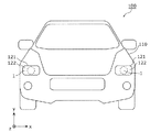
まず、本実施の形態に係る自動車100について、図1を用いて説明する。図1は、本実施の形態に係る自動車100の正面図である。
(Embodiment)
[Automobile (moving body)]
First,
自動車100は、四輪自動車などの移動体の一例である。自動車100は、例えば、ガソリンエンジンで駆動するガソリン自動車、電気で駆動する電気自動車、又は、ハイブリッド自動車などである。
The
図1に示すように、自動車100は、前照灯1と、前照灯1が前方部分に取り付けられた車体110とを備える。具体的には、自動車100は、車体110の前方部分の左右に1つずつ配置された2つの前照灯1を備える。本実施の形態では、自動車100は、さらに、エンジン制御部(ECU:Engine Control Unit)(図示せず)を備える。
As shown in FIG. 1, the
車体110には、図1に示すように、ハウジング121と、前面カバー122とが設けられている。本実施の形態では、ハウジング121と前面カバー122とは、車体110の前方の左右部分に1つずつ設けられている。
As shown in FIG. 1, the
ハウジング121は、例えば、金属製の筐体であって、前照灯1からの光を出射する開口部を有する。前面カバー122は、透光性を有するヘッドランプカバーであり、ハウジング121の開口部に設けられる。ハウジング121と前面カバー122とは、ハウジング121の内部に水又は塵埃などが進入しないように封止されている。
The
前照灯1は、光を前方に出射する灯具であって、本実施の形態では、移動体に搭載されるヘッドライト(車両用前照灯)である。前照灯1は、前面カバー122の後方に配置され、ハウジング121に取り付けられている。前照灯1から出射する光は、前面カバー122を透過して外部に出射する。
The
[前照灯]
次に、本実施の形態に係る前照灯1の詳細について、図2〜図4を用いて説明する。
[Headlight]
Next, the detail of the
図2〜図4はそれぞれ、本実施の形態に係る前照灯1の斜視図、分解斜視図、端面図である。図4は、前照灯1の中心を通る鉛直断面(yz断面)を示している。具体的には、図4は、ロービーム用光源モジュール10の光軸を通る断面であって、前照灯1のレンズ部30が備える第1レンズ体31の中心軸J1と、第2レンズ体32の中心軸J2とを通る断面を示している。
2 to 4 are a perspective view, an exploded perspective view, and an end view of the
前照灯1は、図2及び図3に示すように、ロービーム用光源モジュール10と、ハイビーム用光源モジュール20と、レンズ部30と、放熱体40と、リフレクタ50と、シールド体60と、枠体70とを備える。前照灯1は、さらに、ロービーム用光源モジュール10とハイビーム用光源モジュール20とを制御する照明制御部(図示せず)を備える。
As shown in FIGS. 2 and 3, the
前照灯1は、走行ビームであるハイビームと、すれ違いビームであるロービームとを出射可能な一体型の灯具である。ハイビームは、自動車100の前方の遠方の領域を照射する光である。ロービームは、自動車100の前方の下方の領域を照射する光である。
The
本実施の形態では、前照灯1は、前方(z軸方向の正側)から見た場合に、所定の円形領域内に収まるように構成されている。より具体的には、ロービーム用光源モジュール10と、ハイビーム用光源モジュール20と、レンズ部30と、放熱体40と、リフレクタ50と、シールド体60と、枠体70とは、z軸方向の正側から見た場合に、所定の円形領域内に収まるようにユニット化されている。所定の円形領域の径は、例えば、70mmである。
In the present embodiment, the
なお、本実施の形態に係る前照灯1は、進行方向に対して右側が自車線(走行車線)であり、左側が対向車線である国(例えば、米国)の法規を満たす自動車100に搭載される照明装置の一例である。一方で、進行方向に対して左側が自車線であり、右側が対向車線である国(例えば、日本)の法規を満たす自動車に対しては、以下で説明する構成を左右反転させた前照灯1を搭載すればよい。
The
以下では、前照灯1の各構成部材の詳細について説明する。
Below, the detail of each structural member of the
[ロービーム用光源モジュール]
ロービーム用光源モジュール10は、近距離照明用の光を出射する光源の一例である。具体的には、ロービーム用光源モジュール10は、ロービーム形成用のLED(Light Emitting Diode)モジュールであって、自動車100の前方下方領域(具体的には、路面)を照射するときに点灯する。
[Light source module for low beam]
The low-beam
ロービーム用光源モジュール10は、白色光源であり、例えば青色光を発する青色LEDチップと黄色蛍光体とを用いて白色光を出射するB−Yタイプの白色LED光源である。あるいは、ロービーム用光源モジュール10は、各々が青色光、赤色光及び緑色光を発する複数のLEDチップを用いて白色光を出射する白色LED光源などでもよい。
The low-beam
図3及び図4に示すように、ロービーム用光源モジュール10は、ロービーム用発光素子11と、ロービーム用発光素子11が実装された基板12とを備える。ロービーム用光源モジュール10は、SMD(Surface Mount Device)構造及びCOB(Chip On Board)構造のいずれでもよい。
As shown in FIGS. 3 and 4, the low beam
SMD構造の場合、ロービーム用発光素子11は、例えば、樹脂製の容器内にLEDチップ(ベアチップ)を実装して封止部材(蛍光体含有樹脂)で封入した構成のSMD型のLED素子である。一方、COB構造の場合、ロービーム用発光素子11は、LEDチップ(ベアチップ)そのものであり、LEDチップが基板12に直接実装された構成である。この場合、基板12に実装されたLEDチップは、蛍光体含有樹脂などの封止部材によって封止される。
In the case of the SMD structure, the low beam
ロービーム用光源モジュール10は、放熱体40に固定されている。具体的には、図4に示すように、基板12が放熱部材13を介して放熱体40の所定の載置面41に載置されて固定されている。本実施の形態では、ロービーム用光源モジュール10は、光が上方側に出射するように基板12が横置き(水平置き)で配置されている。つまり、ロービーム用光源モジュール10(ロービーム用発光素子11)の光軸はy軸と平行である。
The low beam
ロービーム用発光素子11は、レンズ部30の第1レンズ体31及び第2レンズ体32を透過する光を発する。ロービーム用発光素子11は、基板12及び放熱部材13を介して放熱体40に熱的に結合されている。
The low-beam
ロービーム用発光素子11は、平面視において、レンズ部30の第1レンズ体31の中心軸J1及び第2レンズ体32の中心軸J2と重なる位置に位置している。すなわち、図4に示すように、中心軸J1及び中心軸J2を通る断面内に、ロービーム用発光素子11が位置している。具体的には、ロービーム用発光素子11は、図4に示す断面において、リフレクタ50の楕円弧形状の焦点(第1焦点)の位置に配置されている。
The low-beam
基板12は、例えば、アルミナなどのセラミックスからなるセラミックス基板、樹脂からなる樹脂基板、又は、金属をベースとして絶縁被覆されたメタルベース基板などである。また、基板12の平面視形状は、基板12が載置される放熱体40の載置面41の形状に応じた形状とすることができる。
The
放熱部材13は、例えば、熱伝導性に優れた液状の放熱シリコーン又はシート状の放熱シートである。放熱部材13は、絶縁性を有する。放熱部材13は、ロービーム用光源モジュール10で発生した熱を放熱体40に伝えることで、効率良く熱を逃がすことができる。
The
[ハイビーム用光源モジュール]
ハイビーム用光源モジュール20は、遠距離照明用の光を出射する光源の一例である。具体的には、ハイビーム用光源モジュール20は、ハイビーム形成用のLEDモジュールであって、自動車100の前方遠方領域を照射するときに点灯する。
[High beam light source module]
The high beam
ハイビーム用光源モジュール20は、白色光源であり、例えば青色光を発する青色LEDチップと黄色蛍光体とを用いて白色光を出射するB−Yタイプの白色LED光源である。あるいは、ハイビーム用光源モジュール20は、各々が青色光、赤色光及び緑色光を発する複数のLEDチップを用いて白色光を出射する白色LED光源などでもよい。
The high beam
図3及び図4に示すように、ハイビーム用光源モジュール20は、ハイビーム用発光素子21と、ハイビーム用発光素子21が実装された基板22とを備える。ハイビーム用光源モジュール20は、SMD構造及びCOB構造のいずれでもよい。SMD構造及びCOB構造の詳細は、ロービーム用光源モジュール10の場合と同様である。
As shown in FIGS. 3 and 4, the high beam
ハイビーム用光源モジュール20は、放熱体40に固定されている。具体的には、図4に示すように、基板22が放熱部材23を介して放熱体40の所定の載置面42に載置されて固定されている。本実施の形態では、ハイビーム用光源モジュール20は、光が前方に出射するように基板22が縦置き(垂直置き)で配置されている。つまり、ハイビーム用光源モジュール20(ハイビーム用発光素子21)の光軸はz軸と平行である。
The high beam
ハイビーム用光源モジュール20とロービーム用光源モジュール10とは、同一の放熱体40に固定されている。具体的には、ハイビーム用光源モジュール20とロービーム用光源モジュール10とはそれぞれ、放熱体40の互いに異なる載置面41及び42に載置されて固定されている。載置面41及び載置面42は、互いに直交する向きに位置している。
The high beam
ハイビーム用発光素子21は、レンズ部30の第1レンズ体31を透過する光を発する。ハイビーム用発光素子21は、基板22及び放熱部材23を介して放熱体40に熱的に結合されている。
The high-beam
ハイビーム用発光素子21は、ロービーム用発光素子11より前方の位置に配置されている。また、例えば、ハイビーム用発光素子21は、第1レンズ体31の中心軸J1より下方、かつ、ロービーム用発光素子11より下方に配置されている。
The high-beam light-emitting
基板22は、例えば、アルミナなどのセラミックスからなるセラミックス基板、樹脂からなる樹脂基板、又は、金属をベースとして絶縁被覆されたメタルベース基板などである。また、基板22の平面視形状は、基板22が載置される放熱体40の載置面42の形状に応じた形状とすることができる。
The
放熱部材23は、例えば、熱伝導性に優れた液状の放熱シリコーン又はシート状の放熱シートである。放熱部材23は、絶縁性を有する。放熱部材23は、ハイビーム用光源モジュール20で発生した熱を放熱体40に伝えることで、効率良く熱を逃がすことができる。
The
[レンズ部]
レンズ部30は、ロービーム用光源モジュール10及びリフレクタ50より前方の位置に配置されている。レンズ部30は、枠体70とシールド体60とに挟まれて固定されている。
[Lens part]
The
レンズ部30は、第1レンズ体31及び第2レンズ体32を有する。本実施の形態では、第1レンズ体31及び第2レンズ体32は、一体に(一部品として)形成されている。第1レンズ体31及び第2レンズ体32は、例えば、アクリル(PMMA)、ポリカーボネート(PC)又は環状オレフィン系の樹脂などの透明樹脂を用いた射出成形により形成されている。なお、第1レンズ体31及び第2レンズ体32は、別体で(別部品として)形成されていてもよい。
The
第1レンズ体31と第2レンズ体32とは、互いに異なる形状を有し、互いに異なる配光特性を有する。第1レンズ体31と第2レンズ体32とは、ロービーム用光源モジュール10から出射された光を透過させて出射する。
The
具体的には、第1レンズ体31は、前方の遠方の狭い第1領域A1を照射する光L1(第1光)を出射する。第2レンズ体32は、前方の近方の広い第2領域A2を照射する光L2(第2光)を出射する。また、第2レンズ体32は、第2領域A2より上方の第3領域A3を照射する光L3(第3光)を出射する。なお、具体的な光の経路については、図6A〜図6C及び図7を用いて後で説明する。
Specifically, the
また、第1レンズ体31は、ハイビーム用光源モジュール20から出射された光を透過させて、第1領域A1よりも遠方の第4領域を照射するように出射する。つまり、本実施の形態では、レンズ部30は、ロービームとハイビームとで兼用される。
Further, the
第1レンズ体31及び第2レンズ体32はそれぞれ、球又は楕円球の一部である。本実施の形態では、図4に示すように、第1レンズ体31の入射面31a及び第2レンズ体32の入射面32aは、平面であり、面一となっている。第1レンズ体31の出射面31b及び第2レンズ体32の出射面32bはそれぞれ、球面又は楕円球面の一部である。出射面31bは、出射面32bより前方に位置している。
Each of the
図2及び図3に示すように、レンズ部30は、前面視において、径の異なる2つの円(大円と小円)の互いの一部が重なった形状を有する。第1レンズ体31の前面視形状は、円(大円)から第2レンズ体32の前方部分を除去した形状である。第2レンズ体32の前面視形状は、円(小円)の一部が直線で切り欠かれた形状である。具体的には、第2レンズ体32の前面視形状は、中心角が180度より大きい弓形である。
As shown in FIGS. 2 and 3, the
第1レンズ体31の中心軸J1は、第1レンズ体31の最前端を通り、入射面31aに直交する仮想線に相当する。第2レンズ体32の中心軸J2は、第2レンズ体32の最前端を通り、入射面32aに直交する仮想線に相当する。中心軸J1及び中心軸J2は、前照灯1の左右方向(x軸方向)における略中央に位置する。したがって、中心軸J1及び中心軸J2を通る面(yz面)は、図4に示す断面であり、前照灯1を左右に分断する基準面に相当する。
The central axis J1 of the
前照灯1から前方を見たときに、当該基準面より左側が自動車100の前方左方であり、対向車線側に相当する(米国基準)。前照灯1から前方を見たときに、当該基準面より右側が自動車100の前方右方であり、自車線側に相当する(米国基準)。
When looking forward from the
第1レンズ体31の焦点距離f1は、入射面31aからフォーカス面F1までの距離である。第2レンズ体32の焦点距離f2は、入射面32aからフォーカス面F2までの距離である。本実施の形態では、図4に示すように、第1レンズ体31の焦点距離f1は、第2レンズ体32の焦点距離f2より長い。焦点距離f1が長い第1レンズ体31は、投影倍率が小さくなるので、狭い配光を実現し、遠方にまで光を照射する。焦点距離f2が短い第2レンズ体32は、投影倍率が大きくなるので、広い配光を実現し、遠方だけでなく近くの領域に光を照射する。
The focal length f1 of the
[放熱体]
放熱体40は、ロービーム用光源モジュール10及びハイビーム用光源モジュール20で発生する熱を外部(大気中)に放熱するための放熱部材である。放熱体40は、例えば、金属などの熱伝導率が高い材料を用いて形成される。具体的には、放熱体40は、アルミニウム合金を用いたアルミダイカスト製である。放熱体40には、複数の放熱フィンが設けられている。
[Heat radiator]
The
図3及び図4に示すように、放熱体40は、載置面41及び載置面42を有する。
As shown in FIGS. 3 and 4, the
載置面41は、放熱体40の外側面の1つであり、中心軸J1及び中心軸J2に平行な面である。具体的には、載置面41は、放熱体40の上面の一部であり、ロービーム用光源モジュール10の光出射方向が上方になるようにロービーム用光源モジュール10が載置される。
The mounting
載置面42は、放熱体40の外側面の1つであり、中心軸J1及び中心軸J2に直交する面である。具体的には、載置面42は、放熱体40の前面の一部であり、ハイビーム用光源モジュール20の光出射方向が前方になるようにハイビーム用光源モジュール20が載置される。
The mounting
[リフレクタ]
リフレクタ50は、ロービーム用光源モジュール10の光出射方向に配置された反射体である。リフレクタ50は、ロービーム用光源モジュール10が出射する光の一部である光L1を第1レンズ体31に向けて反射する(図6Aを参照)。リフレクタ50は、ロービーム用光源モジュール10が出射する光の他の一部である光L2を第2レンズ体32に向けて反射する(図6Bを参照)。リフレクタ50は、ロービーム用光源モジュール10が出射する光の他の一部である光L3をシールド体60に向けて反射する(図6Cを参照)。
[Reflector]
The
リフレクタ50は、第1反射部51と、第2反射部52と、第3反射部53とを有する。本実施の形態では、第1反射部51と、第2反射部52と、第3反射部53とは、一体に(一部品として)形成されている。
The
リフレクタ50は、例えば、耐熱樹脂を用いた樹脂成形によって形成され、その表面に反射膜が形成されている。例えば、耐熱樹脂としては、ポリカーボネートなどを用いることができる。あるいは、耐熱樹脂の代わりに、繊維強化プラスチック(FRP(Fiber Reinforced Plastic))又はBMC(Bulk Molding Compound)を用いてもよい。反射膜は、例えば、アルミ蒸着膜などの金属蒸着膜である。反射膜は、ロービーム用光源モジュール10から出射された光を鏡面反射する。なお、第1反射部51と、第2反射部52と、第3反射部53との少なくとも1つは、別体で(別部品として)形成されていてもよい。
For example, the
第1反射部51は、光L1を第1レンズ体31に向けて反射する。第1反射部51は、リフレクタ50の下端側かつ後端側に位置している。本実施の形態では、図4に示すように、第1反射部51は、中心軸J1と中心軸J2との間に位置している。
The first reflecting
第1反射部51は、ロービーム用光源モジュール10の光軸を通る断面(yz断面)において、楕円弧形状を有する。具体的には、図4に示す断面において、第1反射部51の反射面は、互いの端部が連結された1以上の楕円弧形状を有する。1以上の楕円弧は、例えば、互いの焦点間距離が異なっており、一方の焦点がロービーム用光源モジュール10(ロービーム用発光素子11)の近傍に位置し、他方の焦点Pがシールド体60のカットオフライン形成部61の近傍に位置している。
The first reflecting
第1反射部51は、ロービーム用光源モジュール10の光軸に垂直な断面(xz断面)において、放物線形状を有する。放物線の軸は、上面視において、ロービーム用光源モジュール10に重複している。例えば、放物線の軸は、上面視において、第1レンズ体31の中心軸J1に略一致している。
The first reflecting
第2反射部52は、光L2を第2レンズ体32に向けて反射する。第2反射部52は、リフレクタ50の中央部分(第1反射部51と第3反射部53との間)に位置している。本実施の形態では、図4に示すように、第2反射部52は、ロービーム用光源モジュール10の光軸に交差する位置に位置している。
The second reflecting
第2反射部52は、ロービーム用光源モジュール10の光軸を通る断面(yz断面)において、楕円弧形状を有する。具体的には、図4に示す断面において、第2反射部52の反射面は、互いの端部が連結された1以上の楕円弧形状を有する。1以上の楕円弧は、例えば、互いの焦点間距離が異なっており、一方の焦点がロービーム用光源モジュール10(ロービーム用発光素子11)の近傍に位置している。1以上の楕円弧の他方の焦点Qは、シールド体60のカットオフライン形成部63と、カットオフライン形成部63より所定距離上方の位置との間に位置している。
The second reflecting
本実施の形態では、第1反射部51の楕円弧形状における焦点間距離は、第2反射部52の楕円弧形状における焦点間距離より短い。具体的には、第1反射部51の1以上の楕円弧のうち最大の焦点間距離d1は、第2反射部52の1以上の楕円弧のうち最小の焦点間距離d2より短い。なお、図4に示すように、焦点間距離d2は、ロービーム用発光素子11とカットオフライン形成部63との距離に略一致する。焦点間距離d1は、ロービーム用発光素子11とカットオフライン形成部61との距離に略一致する。
In the present embodiment, the inter-focal distance in the elliptical arc shape of the first reflecting
第2反射部52は、ロービーム用光源モジュール10の光軸に垂直な断面(xz断面)において、放物線形状を有する。放物線の軸は、上面視において、ロービーム用光源モジュール10に重複している。例えば、放物線の軸は、上面視において、第2レンズ体32の中心軸J2に略一致している。
The second reflecting
第2反射部52の反射面は、第1反射部51の反射面、又は、第3反射部53の反射面より大きい。したがって、ロービーム用光源モジュール10から出射された光のうち第2反射部52が反射する光L2の光量は、第1反射部51が反射する光L1の光量、又は、第3反射部53が反射する光L3の光量より多い。
The reflection surface of the
第3反射部53は、光L3をシールド体60に向けて反射する。第3反射部53は、リフレクタ50の上端側かつ前端側に位置している。本実施の形態では、図4に示すように、第3反射部53は、シールド体60のカットオフライン形成部61の上方に位置している。第3反射部53の反射面は、ロービーム用光源モジュール10の光軸に略垂直になっている。
The third reflecting
第3反射部53は、ロービーム用光源モジュール10の光軸を通る断面(yz断面)において、楕円弧形状を有する。具体的には、図4に示す断面において、第2反射部52の反射面は、互いの端部が連結された1以上の楕円弧形状を有する。1以上の楕円弧は、例えば、互いの焦点間距離が異なっており、一方の焦点がロービーム用光源モジュール10(ロービーム用発光素子11)の近傍に位置している。1以上の楕円弧の他方の焦点は、シールド体60の反射面64の近傍に位置している。
The third reflecting
第3反射部53は、ロービーム用光源モジュール10の光軸を通る断面(xy断面)において、放物線形状を有する。放物線の軸は、前面視において、ロービーム用光源モジュール10に重複している。
The third reflecting
なお、第1反射部51、第2反射部52及び第3反射部53の形状は、これらに限定されない。例えば、第3反射部53の形状は、平坦な反射面を有する平板状でもよい。
In addition, the shape of the
[シールド体]
シールド体60は、レンズ部30とロービーム用光源モジュール10との間に配置されている。シールド体60は、リフレクタ50によって反射された光L3を第2レンズ体32に向けて反射する。また、シールド体60は、リフレクタによって反射された光L1及び光L2の各々の一部を遮蔽することで、カットオフラインを形成する。
[Shield body]
The
図5は、本実施の形態に係るシールド体60及びレンズ部30の上面図である。なお、図5には、ロービーム用光源モジュール10から発せられた光Lの経路を分かりやすくするため、リフレクタ50を破線で模式的に示している。
FIG. 5 is a top view of the
シールド体60は、図3に示すように、カットオフライン形成部61と、遮蔽部62と、カットオフライン形成部63と、反射面64と、レンズ支持部65とを備える。
As shown in FIG. 3, the
カットオフライン形成部61は、リフレクタ50の第1反射部51によって反射された光L1の一部を遮蔽することで、照射領域(第1領域A1)の端部にカットオフラインを形成する。カットオフラインは、所定の明暗境界である。図4に示すように、カットオフライン形成部61は、フォーカス面F1内において、第1レンズ体31の中心軸J1と略一致する位置に形成されている。
The cut-off
遮蔽部62は、前面視において、第1レンズ体31の中心軸J1より下方で、かつ、中心軸J1より左方(自車線側)に位置している。具体的には、遮蔽部62は、カットオフライン形成部61からカットオフライン形成部61の前方下方に突出する舌片状の突起である。遮蔽部62は、第1レンズ体31のフォーカス面F1より前方に位置している。
The shielding
遮蔽部62は、反射体50によって反射された光L1の一部を遮蔽する。具体的には、遮蔽部62は、フォーカス面F1の中心軸J1より上方(y軸方向の正側)、かつ、自車線側(x軸方向の負側)を通過する光Lを遮蔽する。なお、図5に示すように、光Lは、第1レンズ体31によって反転投影されて、対向車線側の水平線より下方に到達する光である。すなわち、遮蔽部62は、対向車線側の水平線の下方の部分(具体的には、図7の(c)における×印の近傍)に到達する光を遮蔽する。
The shielding
カットオフライン形成部63は、リフレクタ50の第2反射部52によって反射された光L2の一部を遮蔽することで、照射領域(第2領域A2)の端部にカットオフラインを形成する。なお、カットオフライン形成部61とカットオフライン形成部63との各々が形成するカットオフラインは同じ形状である。図4に示すように、カットオフライン形成部63は、フォーカス面F2内において、第2レンズ体32の中心軸J2と略一致する位置に形成されている。
The cut-off
反射面64は、リフレクタ50の第3反射部53によって反射された光L3を第2レンズ体32に向けて反射する。反射面64は、すり鉢状に湾曲した形状を有する。
The reflecting
レンズ支持部65は、枠体70とともにレンズ部30を挟むことで、レンズ部30を支持する。レンズ支持部65は、レンズ部30の外形に沿って略円環状に形成されている。レンズ支持部65がレンズ部30に当接することで、シールド体60とレンズ部30との位置決めを適切に行うことができる。
The
シールド体60は、例えば、リフレクタ50と同様に、耐熱樹脂又は繊維強化プラスチックなどを用いて形成される。シールド体60の表面には、アルミ蒸着膜などの反射膜が形成されている。なお、反射膜は、シールド体60の表面全体に形成されていなくてもよく、例えば、カットオフライン形成部61及び63、遮蔽部62の上面及び反射面64に形成されていればよい。なお、シールド体60は、アルミニウム製の板金を加工することで形成されてもよい。
The
また、カットオフライン形成部61、遮蔽部62、カットオフライン形成部63、反射面64及びレンズ支持部65が一体に形成されていなくてもよい。例えば、カットオフライン形成部61及び遮蔽部62と、カットオフライン形成部63及び反射面64とがそれぞれ異なる部材で形成されてもよい。あるいは、例えば、シールド体60と放熱体40とは、一体に(一部品として)形成されていてもよい。
Further, the cut-off
[枠体]
枠体70は、レンズ部30をシールド体60との間で挟んで支持する。枠体70は、前面視において、外周が略円形で、かつ、内周がレンズ部30の前面視形状(大円と小円との一部が重なった形状)である略円環状の枠体である。枠体70の外周が、前照灯1の前面視における外形に略一致する。言い換えると、前照灯1が備える各構成部材は、前面視において、枠体70の外周に収まるように配置されている。なお、放熱体40のフィンの一部などは、枠体70からはみ出ていてもよい。
[Frame]
The
枠体70は、例えば、樹脂材料から形成されるが、これに限定されない。枠体70は、金属材料から形成されてもよい。
The
[ロービームの配光]
続いて、前照灯1が出射するロービームの光の経路について、図6A〜図6C及び図7を用いて説明する。
[Low beam light distribution]
Next, the path of the low beam light emitted from the
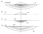
図6A〜図6Cはそれぞれ、本実施の形態に係る前照灯1が出射するロービームのうち、遠方の狭い第1領域A1を照射する光L1、近方の広い第2領域A2を照射する光L2及び上方の第3領域A3を照射する光L3の各々の経路を示す図である。図7は、本実施の形態に係る前照灯1が出射するロービームの照射領域Aを示す図である。
FIGS. 6A to 6C respectively show light L1 that irradiates a distant narrow first region A1 and light that irradiates a distant second region A2 out of the low beam emitted by the
ここで、図7は、例えば、前照灯1から前方に所定距離(例えば、25m)離れた位置に設けられたスクリーンを照射したときの光(光度)の分布を模式的に示している。図7において、紙面上下方向の一点鎖線は、前照灯1の中心軸J1及び中心軸J2の延長線が交差する線であり、自動車100の正面の位置を示している。図7の(a)〜(d)の各々において、紙面左右方向の一点鎖線は、水平線を示している。
Here, FIG. 7 schematically shows, for example, the distribution of light (luminous intensity) when a screen provided at a position a predetermined distance (for example, 25 m) away from the
本実施の形態では、ロービーム用光源モジュール10は、所定の配光角の光を出射する。すなわち、ロービーム用光源モジュール10が点灯したとき、光L1、光L2及び光L3は同時に出射される。これにより、ロービーム用光源モジュール10が点灯したとき、図7の(a)に示すような照射領域Aが形成される。照射領域Aは、図7の(b)〜(d)に示す第1領域A1、第2領域A2及び第3領域A3を合成した領域である。
In the present embodiment, the low beam
まず、光L1について、図6Aを用いて説明する。 First, the light L1 will be described with reference to FIG. 6A.
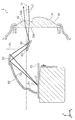
図6Aに示すように、ロービーム用発光素子11からリフレクタ50の第1反射部51に向けて発せられた光L1は、第1反射部51によって反射されて、レンズ部30の第1レンズ体31に向かって進行する。光L1は、第1レンズ体31の入射面31aに入射し、第1レンズ体31を透過して出射面31bから出射される。
As shown in FIG. 6A, the light L <b> 1 emitted from the low-beam
光L1は、図6Aに示すように、第1レンズ体31の中心軸J1に対して小さい角度で第1反射部51から入射面31aまで進行している。すなわち、光L1は、第1レンズ体31の中心軸J1に近い部分に入射する。これにより、第1レンズ体31の中心軸J1に近い部分は色収差が小さいので、光L1の色むらを低減することができる。
As illustrated in FIG. 6A, the light L1 travels from the first reflecting
図7の(c)は、光L1によって照射される第1領域A1を示している。なお、第1領域A1の上端には、カットオフライン形成部61によってカットオフラインCL1が形成されている。
FIG. 7C shows the first region A1 irradiated with the light L1. A cut-off line CL1 is formed by the cut-off
第1レンズ体31は、フォーカス面F1を通る光L1を、所定の投影倍率で拡大し、かつ、反転させて前方に投影する。上述したように、投影倍率は、レンズ体のフォーカス距離に応じて決定される。本実施の形態では、第1レンズ体31のフォーカス距離f1は、第2レンズ体32のフォーカス距離f2より長いので、第1領域A1は、上下方向及び水平方向ともに、第2領域A2(図7の(d))より小さくなる。すなわち、第1領域A1は、第2領域A2より狭い領域になる。
The
また、図7の(c)では、斜め格子の網掛けの疎密によって、光度の差を模式的に示している。第1領域A1では、中央程、光度が高く、周辺程、光度が低くなっている。本実施の形態では、光L1の光度は、光L2の光度より高い。具体的には、第1領域A1において中央部分の光度が最も高く、例えば、40000[cd]以上である。この光度は、光L2の光度(平均値)の10倍以上である。 Further, in FIG. 7C, the difference in luminous intensity is schematically shown by the shading density of the diagonal lattice. In the first region A1, the light intensity is higher at the center and the light intensity is lower at the periphery. In the present embodiment, the light intensity of the light L1 is higher than the light intensity of the light L2. Specifically, in the first region A1, the central portion has the highest luminous intensity, for example, 40000 [cd] or more. This luminous intensity is 10 times or more the luminous intensity (average value) of the light L2.
なお、光L1の一部(図5に示す光L)は、シールド体60の遮蔽部62によって遮蔽される。具体的には、遮蔽部62は、水平線より下方の対向車線側の領域(図7の(c)における×印の近傍)に到達する光を遮蔽する。したがって、当該領域の光度が低くなり、対向車に強い光が照射されるのを抑制することができる。
A part of the light L1 (the light L shown in FIG. 5) is shielded by the shielding
次に、光L2について、図6Bを用いて説明する。 Next, the light L2 will be described with reference to FIG. 6B.
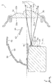
図6Bに示すように、ロービーム用発光素子11からリフレクタ50の第2反射部52に向けて発せられた光L2は、第2反射部52によって反射されて、レンズ部30の第2レンズ体32に向かって進行する。光L2は、第2レンズ体32の入射面32aに入射し、第2レンズ体32を透過して出射面32bから出射される。なお、図6Bに示す点Q1及び点Q2は、第2反射部52の複数の楕円弧形状の他方の焦点Qの一例を示している。
As shown in FIG. 6B, the light L <b> 2 emitted from the low-beam
光L2は、図6Bに示すように、第2レンズ体32の中心軸J2に対して小さい角度で第2反射部52から入射面32aまで進行している。すなわち、光L2は、第2レンズ体32の中心軸J2に近い部分に入射する。これにより、第2レンズ体32の中心軸J2に近い部分は色収差が小さいので、光L2の色むらを低減することができる。
As shown in FIG. 6B, the light L2 travels from the second reflecting
図7の(d)は、光L2によって照射される第2領域A2を示している。なお、第2領域A2の上端には、カットオフライン形成部63によってカットオフラインCL2が形成されている。
FIG. 7D shows the second region A2 irradiated with the light L2. Note that a cut-off line CL2 is formed by the cut-off
第2レンズ体32は、フォーカス面F2を通る光L2を、所定の投影倍率で拡大し、かつ、反転させて前方に投影する。本実施の形態では、第2領域A2は、上下方向及び水平方向ともに、第1領域A1より大きくなる。具体的には、第2領域A2は、第1領域A1より近い領域を含み、かつ、第1領域A1より広い領域である。なお、第2領域A2は、第1領域A1を含んでいる。
The
また、図7の(d)では、ドットの網掛けの疎密によって、光度の差を模式的に示している。第2領域A2では、中央程、光度が高く、周辺程、光度が低くなっている。光L2の光度は、例えば、150[cd]〜5000[cd]である。 In FIG. 7D, the difference in luminous intensity is schematically shown by the density of the shaded dots. In the second region A2, the light intensity is higher at the center and the light intensity is lower at the periphery. The luminous intensity of the light L2 is, for example, 150 [cd] to 5000 [cd].
次に、光L3について、図6Cを用いて説明する。 Next, the light L3 will be described with reference to FIG. 6C.
図6Cに示すように、ロービーム用発光素子11からリフレクタ50の第3反射部53に向けて発せられた光L3は、まず、第3反射部53によって反射されてシールド体60の反射面64に向かって進行する。その後、光L3は、シールド体60の反射面64によって反射されて、第2レンズ体32に向かって進行する。光L3は、第2レンズ体32の入射面32aに入射し、第2レンズ体32を透過して出射面32bから出射される。
As shown in FIG. 6C, the light L3 emitted from the low-beam
光L3は、図6Cに示すように、第2レンズ体32の中心軸J2に対して小さい角度で反射面64から入射面32aまで進行している。すなわち、光L3は、第2レンズ体32の中心軸J2に近い部分に入射する。これにより、第2レンズ体32の中心軸J2に近い部分は色収差が小さいので、光L3の色むらを低減することができる。
As shown in FIG. 6C, the light L3 travels from the reflecting
図7の(b)は、光L3によって照射される第3領域A3を示している。光L3の光度は、光L1の光度に比べて十分に低い。光L3の光度は、例えば、第2領域A2の周辺部分の光度と略同じである。具体的には、光L3の光度は、例えば125[cd]〜700[cd]であり、光L3は、第3領域A3を淡くうっすらと照射する程度の光である。 FIG. 7B shows the third region A3 irradiated with the light L3. The light intensity of the light L3 is sufficiently lower than the light intensity of the light L1. The luminous intensity of the light L3 is, for example, substantially the same as the luminous intensity of the peripheral part of the second region A2. Specifically, the light intensity of the light L3 is, for example, 125 [cd] to 700 [cd], and the light L3 is light that irradiates the third region A3 lightly and lightly.
[ハイビームの配光]
続いて、本実施の形態に係る前照灯1のハイビームの配光を制御する構成について説明する。
[High beam light distribution]
Then, the structure which controls the light distribution of the high beam of the
図8は、本実施の形態に係る前照灯1が出射するハイビームの経路を示す図である。図8は、図4と同じ断面を示している。図9は、本実施の形態に係る前照灯1が出射するハイビームの照射領域を示す図である。
FIG. 8 is a diagram showing a path of a high beam emitted from the
ハイビーム用光源モジュール20は、光軸が中心軸J1に沿って配置されており、前方に光L4を出射する。光L4は、図8に示すように、第1レンズ体31の入射面31aに入射し、第1レンズ体31を透過して出射面31bから出射される。
In the high beam
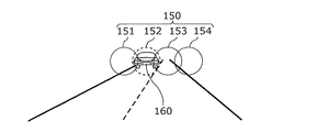
本実施の形態では、図9に示すように、ハイビーム用光源モジュール20は、照射領域(第4領域150)を複数の区画151〜154に分割して光を照射可能である。具体的には、ハイビーム用光源モジュール20は、それぞれ異なる区画を照射する光を出射する複数のハイビーム用発光素子21を備える。
In the present embodiment, as shown in FIG. 9, the high-beam
図10は、本実施の形態に係る前照灯1が搭載された自動車100の機能構成を示すブロック図である。
FIG. 10 is a block diagram illustrating a functional configuration of the
図10に示すように、自動車100は、前照灯1と、エンジン制御部130と、カメラ140とを備える。前照灯1は、ロービーム用光源モジュール10と、ハイビーム用光源モジュール20とを有する。
As shown in FIG. 10, the
エンジン制御部(ECU)130は、自動車100のエンジンを制御する。エンジン制御部130は、例えば、マイクロコンピュータである。エンジン制御部130には、カメラ140と、前照灯1(ロービーム用光源モジュール10及びハイビーム用光源モジュール20)とが接続されている。
The engine control unit (ECU) 130 controls the engine of the
本実施の形態では、エンジン制御部130は、複数のハイビーム用発光素子21の各々の点灯及び消灯を切り替える。具体的には、エンジン制御部130は、カメラ140によって撮影された映像から、光を照射すべきではない対象物の位置を認識する。対象物は、例えば、対向車線を走行する対向車、又は、自車線を走行する前方の車などである。エンジン制御部130は、対象物の位置に相当する区画を特定し、当該区画を照射するハイビーム用発光素子21を消灯(又は減光)する。
In the present embodiment, the
カメラ140は、自動車100の前方を撮影する撮影装置の一例である。カメラ140は、例えば、自動車100のダッシュボード上又はルームミラーの近傍などに取り付けられており、自動車100の前方(自動車100の進行方向)を撮影する。カメラ140が撮影した映像は、エンジン制御部130に出力される。
The
図9に示す例では、ハイビームの照射領域(第4領域150)は、4つの区画151〜154に分割される。対向車160が区画152に位置しているので、エンジン制御部130は、区画152を照射するハイビーム用発光素子21を消灯する。これにより、対向車160の周囲(区画151、153及び154)には光を照射しつつ、対向車160には光を照射しないようにすることができる。
In the example shown in FIG. 9, the high beam irradiation area (fourth area 150) is divided into four
なお、対向車160が区画151に移動した場合には、エンジン制御部130は、区画151を照射するハイビーム用発光素子21を消灯し、区画152を照射するハイビーム用発光素子21を点灯する。このように、本実施の形態によれば、対向車160の位置に応じて、選択的に光を照射する区画を決定することができる。
When the
[効果など]
以上のように、本実施の形態に係る前照灯1は、光を前方に出射する前照灯であって、ロービーム用光源モジュール10と、ロービーム用光源モジュール10の光出射方向に配置されたリフレクタ50と、ロービーム用光源モジュール10及びリフレクタ50より前方の位置に配置された第1レンズ体31及び第2レンズ体32とを備え、リフレクタ50は、ロービーム用光源モジュール10が出射する光の一部である光L1を第1レンズ体31に向けて反射し、かつ、ロービーム用光源モジュール10が出射する光の他の一部である光L2を第2レンズ体32に向けて反射し、第1レンズ体31は、リフレクタ50によって反射された光L1を透過させて、第1領域A1を照射するように出射し、第2レンズ体32は、リフレクタ50によって反射された光L2を透過させて、第1領域A1より近い領域を含み、かつ、第1領域A1より広い領域である第2領域A2を照射するように出射し、光L1の光度は、光L2の光度より高い。また、例えば、本実施の形態に係る自動車100は、前照灯1と、前照灯1が前方部分に取り付けられた車体110とを備える。
[Effects, etc.]
As described above, the
このように、第1レンズ体31が遠方の狭い第1領域A1に光L1を出射し、第2レンズ体32が近方の広い第2領域A2に光L2を出射する。光L2の光度が光L1の光度より低いので、近くの領域のグレアを抑制することができ、かつ、遠くまで光を照射することができる。一般的に、車両に用いる前照灯には、安全に運転する上での法規上の制約が課されている。例えば、路面手前が明るすぎる場合、自動車100の運転者には、遠方が相対的により暗く見えてしまうために、路面手前の光度を抑えることが法規によって要求されている。
As described above, the
本実施の形態に係る前照灯1によれば、特に、自動車100の正面の水平線のやや下に位置するポイントにおける光度を低減することができる。さらに、第1レンズ体31から出射される光L1によって遠方がより明るく照らされる。したがって、自動車100の運転者にとっては、路面手前のグレアが抑制され、かつ、遠方が明るく照らされるので、前方の視認性を高めることができ、容易に安全運転を行うことができる。
According to the
また、例えば、第1レンズ体31の焦点距離f1は、第2レンズ体32の焦点距離f2より長い。
For example, the focal length f1 of the
これにより、第1レンズ体31の焦点距離f1が長いので、投影倍率が小さくなり、狭い配光を実現することができる。第2レンズ体32の焦点距離f2が短いので、投影倍率が大きくなり、広い配光を実現することができる。このように、第1レンズ体31及び第2レンズ体32の焦点距離を適切に設計することで、簡易な形状で、狭配光と広配光とを実現することができる。
Thereby, since the focal distance f1 of the
また、例えば、リフレクタ50は、光L1を第1レンズ体31に向けて反射する第1反射部51と、光L2を第2レンズ体32に向けて反射する第2反射部52とを有し、第1反射部51及び第2反射部52はそれぞれ、ロービーム用光源モジュール10の光軸を通る断面において、楕円弧形状を有し、第1反射部51の楕円弧形状における焦点間距離は、第2反射部52の楕円弧形状における焦点間距離より短い。
For example, the
これにより、第1反射部51及び第2反射部52がそれぞれ、第1レンズ体31及び第2レンズ体32に向けて光L1及び光L2を効率良く反射させることができる。
Thereby, the
また、例えば、さらに、第2レンズ体32とロービーム用光源モジュール10との間に配置されたシールド体60を備え、リフレクタ50は、さらに、ロービーム用光源モジュール10が出射する光の他の一部である光L3をシールド体60に向けて反射し、シールド体60は、リフレクタ50によって反射された光L3を第2レンズ体32に向けて反射し、第2レンズ体32は、さらに、シールド体60によって反射された光L3を透過させて、第2領域A2より上方の第3領域A3を照射するように出射する。
Further, for example, a
これにより、前方の上方に位置する看板又は道路標識などを照射することができるので、自動車100の運転者の安全運転を支援することができる。
As a result, a signboard or road sign positioned above the front can be irradiated, so that the driver of the
また、例えば、シールド体60は、リフレクタ50によって反射された光L2の一部を遮蔽することで、第2領域A2の端部にカットオフラインを形成する。
For example, the
これにより、カットオフラインを形成することで、対向車に光L2が照射されにくくなるので、対向車の運転者に眩しさを感じさせないようにすることができる。これにより、安全で円滑な交通を実現することができる。 Thus, by forming the cut-off line, it is difficult for the oncoming vehicle to be irradiated with the light L2, and thus it is possible to prevent the driver of the oncoming vehicle from feeling dazzled. Thereby, safe and smooth traffic can be realized.
また、例えば、シールド体60は、リフレクタ50によって反射された光L1の一部を遮蔽する遮蔽部62を有し、遮蔽部62は、前面視において、第1レンズ体31の中心軸J1より下方で、かつ、中心軸J1より左方及び右方の一方のみに位置している。
Further, for example, the
これにより、対向車線側の水平線より下方に照射する光Lを遮蔽することができるので、対向車の運転者に眩しさを感じさせないようにすることができる。これにより、安全で円滑な交通を実現することができる。 Thereby, since the light L irradiated below the horizontal line on the oncoming lane side can be blocked, it is possible to prevent the driver of the oncoming vehicle from feeling dazzled. Thereby, safe and smooth traffic can be realized.
また、例えば、前照灯1は、さらに、ロービーム用光源モジュール10が配置された放熱体40と、放熱体40に配置され、第1レンズ体31に向けて光を出射するハイビーム用光源モジュール20とを備え、第1レンズ体31は、ハイビーム用光源モジュール20が出射した光を透過させて、第1領域A1よりも遠方の第4領域150を照射するように出射する。
In addition, for example, the
このように、1つの放熱体40にロービーム用光源モジュール10とハイビーム用光源モジュール20とが配置されている。つまり、前照灯1は、小型化されており、かつ、1つの灯具として、ロービームとハイビームとを照射することができる。したがって、車体110の前方部分のスペースを有効に利用することができる。
As described above, the low-beam
また、例えば、自動車100は、前照灯1と、前照灯1が前方部分に取り付けられた車体110と、前照灯1が接続されたエンジン制御部130とを備え、ハイビーム用光源モジュール20は、第4領域150を複数の区画151〜154に分割して照射可能であり、エンジン制御部130は、複数の区画151〜154のうち照射する区画を決定する。
Further, for example, the
これにより、例えば、対向車160が存在する場合に、対向車160の位置に相当する区画に光を照射しないようにし、かつ、他の区画に光を照射することができる。したがって、自車の運転者にとっての視認性の悪化を抑制しつつ、対向車の運転者に眩しさを感じさせないようにすることができる。これにより、安全で円滑な交通を実現することができる。
Thereby, for example, when the
(変形例1)
以下では、上記の実施の形態に係る前照灯1の変形例1について図面を用いて説明する。
(Modification 1)
Below, the
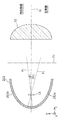
図11は、本変形例に係るリフレクタの水平方向の特性を模式的に示す図である。具体的には、図11は、ロービーム用発光素子11の光軸に垂直な断面であって、リフレクタの第2反射部252と第2レンズ体32とを通る断面(xz断面)を示している。
FIG. 11 is a diagram schematically illustrating the horizontal characteristic of the reflector according to the present modification. Specifically, FIG. 11 shows a cross section perpendicular to the optical axis of the low beam
本変形例に係るリフレクタの第2反射部252は、実施の形態に係る第2反射部52と比較して、xz断面における断面視形状が異なっている。具体的には、第2反射部252は、xz断面において、軸が互いに異なる2つの放物線形状を有する。
The second reflecting
図11に示すように、第2反射部252は、第1放物線部252aと、第2放物線部252bとを有する。第1放物線部252aは、第2レンズ体32の中心軸J2のx軸方向の負側の部分であり、軸P1を有する。第2放物線部252bは、第2レンズ体32の中心軸J2の正側の部分であり、軸P2を有する。
As shown in FIG. 11, the second reflecting
本実施の形態では、軸P1と軸P2とは、互いに交差している。具体的には、軸P1と軸P2とは、y軸方向の正側から見た場合に、ロービーム用発光素子11(ロービーム用光源モジュール10)と重複する位置で交差している。軸P1と軸P2とは、中心軸J2に対して所定の角度で傾斜している。これにより、第2反射部252は、ロービーム用光源モジュール10から出射された光を水平方向(x軸方向)に広げることができる。
In the present embodiment, the axis P1 and the axis P2 intersect each other. Specifically, when viewed from the positive side in the y-axis direction, the axis P1 and the axis P2 intersect at a position overlapping the low-beam light emitting element 11 (low-beam light source module 10). The axis P1 and the axis P2 are inclined at a predetermined angle with respect to the central axis J2. Thereby, the
図11に示す例では、軸P1と軸P2とは、中心軸J2に対する傾きが異なっている。具体的には、軸P1は、中心軸J2に対して角度θ1で傾斜している。軸P2は、中心軸J2に対して角度θ2で傾斜している。このとき、角度θ1は、角度θ2より小さい。すなわち、第2放物線部252bの軸P2は、第1放物線部252aの軸P1より大きく傾斜している。
In the example shown in FIG. 11, the axis P1 and the axis P2 have different inclinations with respect to the central axis J2. Specifically, the axis P1 is inclined at an angle θ1 with respect to the central axis J2. The axis P2 is inclined at an angle θ2 with respect to the central axis J2. At this time, the angle θ1 is smaller than the angle θ2. That is, the axis P2 of the second
第2放物線部252bによって反射された光は、第2レンズ体32を透過して対向車線側に出射される。第1放物線部252aによって反射された光は、第2レンズ体32を透過して自車線側に出射される。軸P2を軸P1より大きく傾けることで、自車線側に出射される光を広げる量より、対向車線側に出射される光を水平方向に広げることができる。
The light reflected by the second
以上のように、本変形例に係る前照灯では、例えば、第2反射部252は、ロービーム用光源モジュール10の光軸に垂直な断面において、軸が互いに交差する2つの放物線形状を有する。
As described above, in the headlamp according to the present modification, for example, the
このように、第2反射部52の放物線形状の軸が互いに交差しているので、光L2を水平方向に広げて進行させることができる。これにより、光L2が照射する第2領域A2を水平方向に広げることができるので、より広い範囲を明るくすることができる。
Thus, since the parabolic axes of the second reflecting
また、例えば、2つの放物線形状の各々の軸は、ロービーム用光源モジュール10の光軸方向から見た場合に、ロービーム用光源モジュール10と重複する位置で交差している。
Further, for example, the axes of the two parabolic shapes intersect each other at a position overlapping the low beam
これにより、ロービーム用光源モジュール10からの光の反射方向を制御しやすくなるので、所望の照明領域を形成しやすくなる。
This makes it easy to control the reflection direction of light from the low-beam
また、例えば、2つの放物線形状の各々の軸は、ロービーム用光源モジュール10の光軸方向から見た場合に、第2レンズ体32の中心軸J2に対する傾きが異なっている。
Further, for example, the respective axes of the two parabolic shapes have different inclinations with respect to the central axis J <b> 2 of the
これにより、第2領域A2の水平方向において左右で広げる量を異ならせることができる。例えば、対向車線側の照射領域をより外方(左方(米国基準))に広げることができるので、道路の路肩のより広い範囲を明るくすることができる。これにより、安全で円滑な交通を実現することができる。 As a result, the amount of expansion in the horizontal direction of the second region A2 can be varied. For example, since the irradiation area on the opposite lane side can be expanded outward (leftward (US standard)), a wider area of the road shoulder can be brightened. Thereby, safe and smooth traffic can be realized.
なお、本変形例では、第2反射部52の放物線形状について説明したが、第1反射部51又は第3反射部53について、同様の形状を有してもよい。これにより、第1領域A1又は第3領域A3を水平方向に広げることができる。
In addition, although the parabolic shape of the
(変形例2)
続いて、上記の実施の形態に係る前照灯1の変形例2について図面を用いて説明する。
(Modification 2)
Then, the modification 2 of the
上記の実施の形態に係る前照灯1では、レンズ部30の入射面、すなわち、第1レンズ体31の入射面31aと第2レンズ体32の入射面32aとが面一である例に点いて示したが、これに限らない。
In the
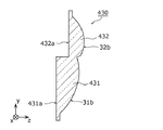
図12A及び図12Bはそれぞれ、本変形例に係るレンズ部330及び430の断面図である。
12A and 12B are cross-sectional views of
図12Aに示すように、レンズ部330は、第1レンズ体331と、第2レンズ体332とを有する。第1レンズ体331の入射面331aと、第2レンズ体332の入射面332aとは、面一ではなく、前後方向(z軸方向)において異なる位置に位置している。具体的には、入射面331aが入射面332aより前方に位置している。
As illustrated in FIG. 12A, the
なお、第1レンズ体331及び第2レンズ体332の形状は、上記の実施の形態に係る第1レンズ体31及び第2レンズ体32と同じである。すなわち、第1レンズ体331の焦点距離は、第2レンズ体332の焦点距離より長い。
The shapes of the
また、図12Bに示すように、レンズ部430は、第1レンズ体431と、第2レンズ体432とを有する。第1レンズ体431の入射面431aと、第2レンズ体432の入射面432aとは、面一ではなく、前後方向(z軸方向)において異なる位置に位置している。具体的には、入射面431aが入射面432aより後方に位置している。
In addition, as illustrated in FIG. 12B, the
なお、第1レンズ体431及び第2レンズ体432の形状は、上記の実施の形態に係る第1レンズ体31及び第2レンズ体32と同じである。すなわち、第1レンズ体431の焦点距離は、第2レンズ体432の焦点距離より長い。
The shapes of the
上述したように、レンズ体の焦点距離に応じて投影倍率が異なり、配光を異ならせることができるので、入射面の位置には特に限定されない。 As described above, the projection magnification varies depending on the focal length of the lens body, and the light distribution can be made different. Therefore, the position of the incident surface is not particularly limited.
(その他)
以上、本発明に係る前照灯及び移動体について、上記実施の形態及びその変形例に基づいて説明したが、本発明は、上記の実施の形態に限定されるものではない。
(Other)
As mentioned above, although the headlamp and the moving body which concern on this invention were demonstrated based on the said embodiment and its modification, this invention is not limited to said embodiment.
また、例えば、第1レンズ体31の焦点距離f1と第2レンズ体32の焦点距離f2とは同じでもよい。例えば、図示しない遮蔽部材などを用いて広配光及び狭配光を実現してもよい。
For example, the focal length f1 of the
また、例えば、上記の実施の形態では、自動車100が2つの前照灯1を備える例について示したが、これに限らない。例えば、自動車100は、車体110の左右に2つずつの前照灯1を備えてもよい。すなわち、自動車100は、3つ以上の前照灯1を備えてもよく、あるいは、1つのみの前照灯1を備えてもよい。
Further, for example, in the above embodiment, the example in which the
また、例えば、上記の実施の形態では、前照灯1は、ロービーム及びハイビームを照射する前照灯を例に示したが、フォグランプ又はDRL(Daytime Running Light)でもよい。
Further, for example, in the above embodiment, the
また、例えば、上記の実施の形態では、発光素子の一例としてLEDを示したが、半導体レーザなどのレーザ素子、有機EL(Electro Luminescence)又は無機EL素子などの発光素子を用いてもよい。 For example, in the above embodiment, an LED is shown as an example of a light emitting element, but a laser element such as a semiconductor laser, a light emitting element such as an organic EL (Electro Luminescence), or an inorganic EL element may be used.
また、例えば、上記の実施の形態では、移動体の一例として自動車100を示したが、これに限定されない。移動体は、二輪自動車などでもよい。
For example, in the above-described embodiment, the
その他、各実施の形態に対して当業者が思いつく各種変形を施して得られる形態や、本発明の趣旨を逸脱しない範囲で各実施の形態における構成要素及び機能を任意に組み合わせることで実現される形態も本発明に含まれる。 In addition, the embodiment can be realized by arbitrarily combining the components and functions in each embodiment without departing from the scope of the present invention, or a form obtained by subjecting each embodiment to various modifications conceived by those skilled in the art. Forms are also included in the present invention.
1 前照灯
10 ロービーム用光源モジュール(光源)
20 ハイビーム用光源モジュール(ハイビーム用光源)
31、331、431 第1レンズ体
31a、32a、331a、332a、431a、432a 入射面
31b、32b 出射面
32、332、432 第2レンズ体
40 放熱体
50 リフレクタ(反射体)
51 第1反射部
52、252 第2反射部
53 第3反射部
60 シールド体
61、63 カットオフライン形成部
64 反射面
100 自動車(移動体)
110 車体
130 エンジン制御部
150 第4領域
151、152、153、154 区画
252a 第1放物線部
252b 第2放物線部
A1 第1領域
A2 第2領域
A3 第3領域
CL1、CL2 カットオフライン
J1、J2 中心軸
L1 光(第1光)
L2 光(第2光)
L3 光(第3光)
L4 光
P、Q 焦点
P1、P2 軸
1
20 High beam light source module (High beam light source)
31, 331, 431
51 1st reflection part 52,252
110
L2 light (second light)
L3 light (third light)
L4 Light P, Q Focus P1, P2 axis
Claims (12)
光源と、
前記光源の光出射方向に配置された反射体と、
前記光源及び前記反射体より前記前方の位置に配置された第1レンズ体及び第2レンズ体とを備え、
前記反射体は、前記光源が出射する光の一部である第1光を前記第1レンズ体に向けて反射し、かつ、前記光源が出射する光の他の一部である第2光を前記第2レンズ体に向けて反射し、
前記第1レンズ体は、前記反射体によって反射された前記第1光を透過させて、第1領域を照射するように出射し、
前記第2レンズ体は、前記反射体によって反射された前記第2光を透過させて、前記第1領域より近い領域を含み、かつ、前記第1領域より広い領域である第2領域を照射するように出射し、
前記第1光の光度は、前記第2光の光度より高い
前照灯。 A headlamp that emits light forward,
A light source;
A reflector disposed in the light emitting direction of the light source;
A first lens body and a second lens body disposed at a position in front of the light source and the reflector;
The reflector reflects the first light, which is a part of the light emitted from the light source, toward the first lens body, and the second light, which is the other part of the light emitted from the light source. Reflected toward the second lens body;
The first lens body transmits the first light reflected by the reflector and emits the first region so as to irradiate the first area;
The second lens body transmits the second light reflected by the reflector and irradiates a second region that includes a region closer to the first region and is wider than the first region. Emanating and
A headlamp in which the luminous intensity of the first light is higher than the luminous intensity of the second light.
請求項1に記載の前照灯。 The headlamp according to claim 1, wherein a focal length of the first lens body is longer than a focal length of the second lens body.
前記第1光を前記第1レンズ体に向けて反射する第1反射部と、
前記第2光を前記第2レンズ体に向けて反射する第2反射部とを有し、
前記第1反射部及び前記第2反射部はそれぞれ、前記光源の光軸を通る断面において、楕円弧形状を有し、
前記第1反射部の楕円弧形状における焦点間距離は、前記第2反射部の楕円弧形状における焦点間距離より短い
請求項1又は2に記載の前照灯。 The reflector is
A first reflecting portion that reflects the first light toward the first lens body;
A second reflecting portion that reflects the second light toward the second lens body;
Each of the first reflecting portion and the second reflecting portion has an elliptical arc shape in a cross section passing through the optical axis of the light source,
The headlamp according to claim 1 or 2, wherein an interfocal distance in the elliptical arc shape of the first reflecting portion is shorter than an interfocal distance in the elliptical arc shape of the second reflecting portion.
請求項3に記載の前照灯。 The headlamp according to claim 3, wherein the second reflecting portion has two parabolic shapes whose axes intersect each other in a cross section perpendicular to the optical axis of the light source.
請求項4に記載の前照灯。 The headlamp according to claim 4, wherein each axis of the two parabolic shapes intersects with the light source when viewed from the optical axis direction of the light source.
請求項4又は5に記載の前照灯。 6. The headlamp according to claim 4, wherein the axes of the two parabolic shapes have different inclinations with respect to a central axis of the second lens body when viewed from an optical axis direction of the light source.
前記第2レンズ体と前記光源との間に配置されたシールド体を備え、
前記反射体は、さらに、前記光源が出射する光の他の一部である第3光を前記シールド体に向けて反射し、
前記シールド体は、前記反射体によって反射された前記第3光を前記第2レンズ体に向けて反射し、
前記第2レンズ体は、さらに、前記シールド体によって反射された前記第3光を透過させて、前記第2領域より上方の第3領域を照射するように出射する
請求項1〜6のいずれか1項に記載の前照灯。 further,
A shield body disposed between the second lens body and the light source;
The reflector further reflects third light, which is another part of the light emitted from the light source, toward the shield body,
The shield body reflects the third light reflected by the reflector toward the second lens body,
The second lens body further transmits the third light reflected by the shield body and emits it so as to irradiate a third region above the second region. The headlamp according to item 1.
請求項7に記載の前照灯。 The headlamp according to claim 7, wherein the shield body forms a cut-off line at an end of the second region by shielding a part of the second light reflected by the reflector.
前記遮蔽部は、前面視において、前記第1レンズ体の中心軸より下方で、かつ、当該中心軸より左方及び右方の一方のみに位置している
請求項7又は8に記載の前照灯。 The shield body has a shielding portion that shields a part of the first light reflected by the reflector,
The headlamp according to claim 7 or 8, wherein the shielding portion is located below the center axis of the first lens body and only one of left and right sides with respect to the center axis in front view. light.
前記前照灯は、さらに、
前記光源が配置された放熱体と、
前記放熱体に配置され、前記第1レンズ体に向けて光を出射するハイビーム用光源とを備え、
前記第1レンズ体は、前記ハイビーム用光源が出射した光を透過させて、前記第1領域よりも遠方の第4領域を照射するように出射する
請求項1〜9のいずれか1項に記載の前照灯。 The light source is a low beam light source;
The headlamp further includes:
A radiator in which the light source is disposed;
A high beam light source disposed on the heat dissipating body and emitting light toward the first lens body;
The said 1st lens body permeate | transmits the light which the said high beam light source radiate | emitted, and radiate | emits so that it may irradiate the 4th area | region far from the said 1st area | region. Headlamps.
前記前照灯が前方部分に取り付けられた車体と、
前記前照灯が接続されたエンジン制御部とを備え、
前記ハイビーム用光源は、前記第4領域を複数の区画に分割して照射可能であり、
前記エンジン制御部は、前記複数の区画のうち照射する区画を決定する
移動体。 A headlamp according to claim 10;
A vehicle body with the headlamp attached to the front part;
An engine control unit to which the headlamp is connected,
The high beam light source can irradiate the fourth region by dividing it into a plurality of sections,
The engine control unit determines a section to be irradiated among the plurality of sections.
前記前照灯が前方部分に取り付けられた車体とを備える
移動体。 The headlamp according to any one of claims 1 to 10,
A moving body comprising: a vehicle body having the headlamp attached to a front portion thereof.
Priority Applications (4)
| Application Number | Priority Date | Filing Date | Title |
|---|---|---|---|
| JP2015238021A JP2017103189A (en) | 2015-12-04 | 2015-12-04 | Headlamps and moving objects |
| DE102016122860.5A DE102016122860A1 (en) | 2015-12-04 | 2016-11-28 | Headlight and moving object |
| US15/364,494 US10239443B2 (en) | 2015-12-04 | 2016-11-30 | Headlamp and mobile object |
| CN201611095076.2A CN106838758A (en) | 2015-12-04 | 2016-12-01 | Headlamp and moving body |
Applications Claiming Priority (1)
| Application Number | Priority Date | Filing Date | Title |
|---|---|---|---|
| JP2015238021A JP2017103189A (en) | 2015-12-04 | 2015-12-04 | Headlamps and moving objects |
Publications (1)
| Publication Number | Publication Date |
|---|---|
| JP2017103189A true JP2017103189A (en) | 2017-06-08 |
Family
ID=58722514
Family Applications (1)
| Application Number | Title | Priority Date | Filing Date |
|---|---|---|---|
| JP2015238021A Pending JP2017103189A (en) | 2015-12-04 | 2015-12-04 | Headlamps and moving objects |
Country Status (4)
| Country | Link |
|---|---|
| US (1) | US10239443B2 (en) |
| JP (1) | JP2017103189A (en) |
| CN (1) | CN106838758A (en) |
| DE (1) | DE102016122860A1 (en) |
Cited By (12)
| Publication number | Priority date | Publication date | Assignee | Title |
|---|---|---|---|---|
| JP2019061752A (en) * | 2017-09-22 | 2019-04-18 | 日亜化学工業株式会社 | Light emitting module and vehicle lamp |
| WO2020080512A1 (en) * | 2018-10-19 | 2020-04-23 | 株式会社小糸製作所 | Vehicle lamp, lamp unit and reflector module |
| JP2020090228A (en) * | 2018-12-06 | 2020-06-11 | トヨタ自動車株式会社 | Vehicle headlights |
| WO2020137635A1 (en) * | 2018-12-25 | 2020-07-02 | 株式会社小糸製作所 | Optical unit and method for determining reflection plane |
| JP2021517334A (en) * | 2019-02-26 | 2021-07-15 | ハスコ ビジョン テクノロジー カンパニー リミテッド | Vehicle lamp module and automobiles using it |
| EP3885645A1 (en) | 2020-03-27 | 2021-09-29 | Nichia Corporation | Lighting device and headlight |
| WO2021261559A1 (en) * | 2020-06-24 | 2021-12-30 | 市光工業株式会社 | Vehicle lighting device |
| JP2022541313A (en) * | 2020-04-14 | 2022-09-22 | ツェットカーヴェー グループ ゲーエムベーハー | Irradiation device for automobile floodlight |
| WO2023277071A1 (en) * | 2021-06-30 | 2023-01-05 | 市光工業株式会社 | Vehicle lamp |
| JP2023501667A (en) * | 2019-12-04 | 2023-01-18 | ▲華▼域▲視▼▲覺▼科技(上▲海▼)有限公司 | Vehicle lamp module and vehicle lamp |
| US11578850B2 (en) | 2020-12-22 | 2023-02-14 | Nichia Corporation | Lighting device |
| WO2023162906A1 (en) * | 2022-02-25 | 2023-08-31 | 一博 松本 | Vehicle lamp |
Families Citing this family (24)
| Publication number | Priority date | Publication date | Assignee | Title |
|---|---|---|---|---|
| JPWO2018003888A1 (en) * | 2016-06-29 | 2019-04-25 | 株式会社小糸製作所 | Vehicle lamp |
| CN107343337B (en) * | 2017-01-09 | 2024-01-30 | 广州夜眼科技有限公司 | Dual-color temperature-switching automobile LED headlight |
| FR3069046B1 (en) * | 2017-07-17 | 2020-11-13 | Valeo Vision | BIFUNCTIONAL LIGHT MODULE |
| FR3073179B1 (en) * | 2017-11-08 | 2021-05-28 | Psa Automobiles Sa | MAIN BEAM AND NARROW BEAM LIGHTING DEVICE ADJUSTABLE DEPENDING ON THE POSITION OF AN OBSTACLE DETECTED IN FRONT OF A VEHICLE |
| JP6933961B2 (en) * | 2017-11-17 | 2021-09-08 | 株式会社小糸製作所 | Two-color molded lens |
| CN108278572A (en) * | 2018-02-23 | 2018-07-13 | 重庆舜辉庆驰光电科技有限公司 | The double optical lens automobile fronts of LED bifocus |
| WO2019214977A1 (en) * | 2018-05-08 | 2019-11-14 | Lumileds Holding B.V. | Headlamp for automotive vehicles |
| CN110454744B (en) * | 2018-05-08 | 2022-05-03 | 深圳市绎立锐光科技开发有限公司 | A light source module and a vehicle headlamp |
| JP7184539B2 (en) * | 2018-05-24 | 2022-12-06 | スタンレー電気株式会社 | LIGHTING CONTROL DEVICE, VEHICLE LAMP, AND LIGHTING CONTROL METHOD |
| CN108730914B (en) * | 2018-05-31 | 2020-10-09 | 亳州易泽信息科技有限公司 | A car sunshade for reducing the influence of high beam lights when passing vehicles |
| JP7263842B2 (en) * | 2019-02-28 | 2023-04-25 | 市光工業株式会社 | vehicle lamp |
| JP7265922B2 (en) * | 2019-04-22 | 2023-04-27 | スタンレー電気株式会社 | vehicle headlight |
| JP7279513B2 (en) * | 2019-05-24 | 2023-05-23 | 市光工業株式会社 | vehicle lamp |
| US10655809B1 (en) * | 2019-06-26 | 2020-05-19 | North American Lighting, Inc. | Vehicle lamp |
| EP3772610B1 (en) * | 2019-08-06 | 2022-04-20 | Nichia Corporation | Lighting device |
| JP7467500B2 (en) * | 2019-12-04 | 2024-04-15 | 株式会社小糸製作所 | Vehicle headlights |
| TWI709710B (en) * | 2020-05-28 | 2020-11-11 | 樺薪光電有限公司 | Vehicle lighting device |
| CN113757614B (en) * | 2020-06-02 | 2024-06-04 | 桦薪光电有限公司 | Lighting device for vehicle |
| US11435050B2 (en) | 2020-07-17 | 2022-09-06 | J.W. Speaker Corporation | Bi-functional optical systems and methods |
| CN113028357A (en) * | 2021-03-04 | 2021-06-25 | 超视界激光科技(苏州)有限公司 | Lighting lamp |
| US12419152B2 (en) | 2021-04-16 | 2025-09-16 | Lumileds Singapore Pte. Ltd. | Light-emitting diode (LED) device with indentations |
| DE102021206735A1 (en) * | 2021-06-29 | 2022-12-29 | Psa Automobiles Sa | Headlight module of a vehicle headlight, vehicle headlight and vehicle having the vehicle headlight |
| DE102021117875A1 (en) * | 2021-07-12 | 2023-01-12 | HELLA GmbH & Co. KGaA | headlight for a vehicle |
| KR20240063649A (en) * | 2022-11-03 | 2024-05-10 | 현대모비스 주식회사 | Lamp for vehicle |
Family Cites Families (13)
| Publication number | Priority date | Publication date | Assignee | Title |
|---|---|---|---|---|
| JP4068387B2 (en) * | 2002-04-23 | 2008-03-26 | 株式会社小糸製作所 | Light source unit |
| JP4413762B2 (en) | 2004-12-07 | 2010-02-10 | 株式会社小糸製作所 | Lighting fixtures for vehicles |
| JP4663548B2 (en) | 2006-02-24 | 2011-04-06 | 株式会社小糸製作所 | Vehicle headlamp lamp unit |
| JP5524470B2 (en) * | 2008-11-12 | 2014-06-18 | 株式会社小糸製作所 | Vehicle lamp unit and vehicle lamp |
| JP5519400B2 (en) | 2010-05-20 | 2014-06-11 | 株式会社小糸製作所 | Lighting fixtures for vehicles |
| TWM405382U (en) * | 2010-11-26 | 2011-06-11 | Sirius Light Technology Co Ltd | vehicle lamp |
| JP5831788B2 (en) * | 2011-07-01 | 2015-12-09 | スタンレー電気株式会社 | Vehicle lamp unit |
| JP2013016400A (en) * | 2011-07-05 | 2013-01-24 | Koito Mfg Co Ltd | Vehicular headlight |
| JP6154169B2 (en) * | 2013-03-29 | 2017-06-28 | 株式会社小糸製作所 | Vehicle headlamp |
| JP6207874B2 (en) * | 2013-04-25 | 2017-10-04 | 本田技研工業株式会社 | Lamp unit for vehicle lamp |
| JP6663164B2 (en) * | 2014-02-24 | 2020-03-11 | 株式会社小糸製作所 | Vehicle lighting unit |
| JP2015170423A (en) * | 2014-03-05 | 2015-09-28 | 株式会社小糸製作所 | Vehicle lighting |
| JP2016076389A (en) * | 2014-10-07 | 2016-05-12 | 株式会社小糸製作所 | Vehicle lighting |
-
2015
- 2015-12-04 JP JP2015238021A patent/JP2017103189A/en active Pending
-
2016
- 2016-11-28 DE DE102016122860.5A patent/DE102016122860A1/en not_active Withdrawn
- 2016-11-30 US US15/364,494 patent/US10239443B2/en active Active
- 2016-12-01 CN CN201611095076.2A patent/CN106838758A/en active Pending
Cited By (29)
| Publication number | Priority date | Publication date | Assignee | Title |
|---|---|---|---|---|
| JP2019061752A (en) * | 2017-09-22 | 2019-04-18 | 日亜化学工業株式会社 | Light emitting module and vehicle lamp |
| WO2020080512A1 (en) * | 2018-10-19 | 2020-04-23 | 株式会社小糸製作所 | Vehicle lamp, lamp unit and reflector module |
| JP7339274B2 (en) | 2018-10-19 | 2023-09-05 | 株式会社小糸製作所 | vehicle lamp |
| JPWO2020080512A1 (en) * | 2018-10-19 | 2021-09-09 | 株式会社小糸製作所 | Vehicle lighting fixtures, lighting fixture units and reflector modules |
| JP7017504B2 (en) | 2018-12-06 | 2022-02-08 | トヨタ自動車株式会社 | Vehicle headlights |
| JP2020090228A (en) * | 2018-12-06 | 2020-06-11 | トヨタ自動車株式会社 | Vehicle headlights |
| US11280466B2 (en) | 2018-12-25 | 2022-03-22 | Koito Manufacturing Co., Ltd. | Optical unit and method for determining reflection plane |
| JPWO2020137635A1 (en) * | 2018-12-25 | 2021-11-04 | 株式会社小糸製作所 | Optical unit and reflection surface determination method |
| JP7856695B2 (en) | 2018-12-25 | 2026-05-11 | 株式会社小糸製作所 | Optical unit and method for determining the reflective surface |
| JP7551240B2 (en) | 2018-12-25 | 2024-09-17 | 株式会社小糸製作所 | Optical Unit |
| WO2020137635A1 (en) * | 2018-12-25 | 2020-07-02 | 株式会社小糸製作所 | Optical unit and method for determining reflection plane |
| JP2024099853A (en) * | 2018-12-25 | 2024-07-25 | 株式会社小糸製作所 | Optical unit and method for determining reflecting surface |
| JP2021517334A (en) * | 2019-02-26 | 2021-07-15 | ハスコ ビジョン テクノロジー カンパニー リミテッド | Vehicle lamp module and automobiles using it |
| JP7127932B2 (en) | 2019-02-26 | 2022-08-30 | ハスコ ビジョン テクノロジー カンパニー リミテッド | VEHICLE LAMP MODULE AND AUTOMOTIVE USING THE SAME |
| JP7404532B2 (en) | 2019-12-04 | 2023-12-25 | ▲華▼域▲視▼▲覺▼科技(上▲海▼)有限公司 | Vehicle lamp module and vehicle lamp |
| JP2023501667A (en) * | 2019-12-04 | 2023-01-18 | ▲華▼域▲視▼▲覺▼科技(上▲海▼)有限公司 | Vehicle lamp module and vehicle lamp |
| US11221122B2 (en) | 2020-03-27 | 2022-01-11 | Nichia Corporation | Lighting device and headlight having a reflector, lenses and light-shielding members |
| EP3885645A1 (en) | 2020-03-27 | 2021-09-29 | Nichia Corporation | Lighting device and headlight |
| JP2022541313A (en) * | 2020-04-14 | 2022-09-22 | ツェットカーヴェー グループ ゲーエムベーハー | Irradiation device for automobile floodlight |
| JP7342240B2 (en) | 2020-04-14 | 2023-09-11 | ツェットカーヴェー グループ ゲーエムベーハー | Illumination device for automobile floodlights |
| JP7447698B2 (en) | 2020-06-24 | 2024-03-12 | 市光工業株式会社 | Vehicle lights |
| JP2022022493A (en) * | 2020-06-24 | 2022-02-07 | 市光工業株式会社 | Vehicular lighting fixture |
| WO2021261559A1 (en) * | 2020-06-24 | 2021-12-30 | 市光工業株式会社 | Vehicle lighting device |
| US11578850B2 (en) | 2020-12-22 | 2023-02-14 | Nichia Corporation | Lighting device |
| JP2023006119A (en) * | 2021-06-30 | 2023-01-18 | 市光工業株式会社 | Vehicle lighting fixture |
| WO2023277071A1 (en) * | 2021-06-30 | 2023-01-05 | 市光工業株式会社 | Vehicle lamp |
| JP7605048B2 (en) | 2021-06-30 | 2024-12-24 | 市光工業株式会社 | Vehicle lighting fixtures |
| US12366338B2 (en) | 2021-06-30 | 2025-07-22 | Ichikoh Industries, Ltd. | Vehicle lamp |
| WO2023162906A1 (en) * | 2022-02-25 | 2023-08-31 | 一博 松本 | Vehicle lamp |
Also Published As
| Publication number | Publication date |
|---|---|
| DE102016122860A1 (en) | 2017-06-08 |
| US20170158113A1 (en) | 2017-06-08 |
| CN106838758A (en) | 2017-06-13 |
| US10239443B2 (en) | 2019-03-26 |
Similar Documents
| Publication | Publication Date | Title |
|---|---|---|
| CN106838758A (en) | Headlamp and moving body | |
| JP6340719B2 (en) | LIGHTING DEVICE AND AUTOMOBILE WITH LIGHTING DEVICE | |
| CN105814361B (en) | Headlamp module and front lamp device | |
| CN105972531A (en) | Illumination device and mobile body equipped with illumination device | |
| EP2187115A2 (en) | Vehicular lamp | |
| JP6319725B2 (en) | LIGHTING DEVICE AND AUTOMOBILE WITH LIGHTING DEVICE | |
| JP5897913B2 (en) | Lamp unit | |
| CN108375048A (en) | On-vehicle lamp | |
| CN105387405B (en) | Lighting device and automobile | |
| US8256942B2 (en) | Vehicle headlamp | |
| EP2570715A2 (en) | Vehicle headlamp | |
| JP2011025820A (en) | Vehicular lighting fixture | |
| JP2015170388A (en) | Vehicle headlamp | |
| JP2015079614A (en) | Automotive headlamp | |
| KR102006319B1 (en) | Vehicle lighting unit | |
| JP6443676B2 (en) | LIGHTING DEVICE AND MOBILE BODY HAVING LIGHTING DEVICE | |
| JP7628050B2 (en) | Vehicle lighting fixtures | |
| JP2016149252A (en) | Vehicular head lamp | |
| JP2016170910A (en) | Luminaire and movable body including luminaire | |
| JP2016170880A (en) | Luminaire and movable body including luminaire | |
| JP2016219210A (en) | Illuminating device and automobile including illuminating device | |
| JP6162418B2 (en) | Lamp unit and projection lens | |
| JP2019040677A (en) | Vehicle headlamp | |
| JP6402592B2 (en) | Vehicle headlamp | |
| JP6340687B2 (en) | LIGHTING DEVICE AND AUTOMOBILE WITH LIGHTING DEVICE |