JP2017103190A - Carbon heater and method of manufacturing carbon heater - Google Patents
Carbon heater and method of manufacturing carbon heater Download PDFInfo
- Publication number
- JP2017103190A JP2017103190A JP2015238068A JP2015238068A JP2017103190A JP 2017103190 A JP2017103190 A JP 2017103190A JP 2015238068 A JP2015238068 A JP 2015238068A JP 2015238068 A JP2015238068 A JP 2015238068A JP 2017103190 A JP2017103190 A JP 2017103190A
- Authority
- JP
- Japan
- Prior art keywords
- carbon
- carbon heater
- heater
- electrical resistivity
- base material
- Prior art date
- Legal status (The legal status is an assumption and is not a legal conclusion. Google has not performed a legal analysis and makes no representation as to the accuracy of the status listed.)
- Granted
Links
Images




Landscapes
- Resistance Heating (AREA)
- Ceramic Products (AREA)
- Carbon And Carbon Compounds (AREA)
Abstract
【課題】本発明の目的は、正確な抵抗値を有し、発熱分布が均一で、かつ長寿命なカーボンヒーターおよびその製造方法を提供することである。【解決手段】本発明は、電気抵抗率について実質的に2D直交異方性を有するカーボン基材から成り、主たる発熱部が略円筒形状または略円盤形状のカーボンヒーターであって、カーボンヒーター中心軸方向は、カーボン基材における電気抵抗率の異方性方向と実質的に一致することを特徴とする。また、主たる発熱部が回転対称性または螺旋対称性を有する形状のカーボンヒーターであって、カーボンヒーター形状の回転軸方向または螺旋軸方向は、カーボン基材における電気抵抗率の異方性方向と実質的に一致することを特徴とする。【選択図】図2An object of the present invention is to provide a carbon heater having an accurate resistance value, a uniform heat generation distribution, and a long life, and a method for producing the same. The present invention is a carbon heater composed of a carbon base material having substantially 2D orthogonal anisotropy in terms of electrical resistivity, and a main heat generating portion having a substantially cylindrical shape or a substantially disk shape, and comprising a carbon heater central axis The direction is characterized in that it substantially coincides with the anisotropic direction of electrical resistivity in the carbon substrate. Further, the main heating part is a carbon heater having a shape having rotational symmetry or spiral symmetry, and the rotation axis direction or the helical axis direction of the carbon heater shape is substantially the same as the anisotropic direction of the electrical resistivity in the carbon substrate. It is characterized by matching. [Selection] Figure 2
Description
本発明は、半導体、LED及び太陽電池製造装置等で使用されるカーボンヒーターおよびその製造方法に関する。 The present invention relates to a carbon heater used in a semiconductor, LED, solar cell manufacturing apparatus, and the like and a manufacturing method thereof.
カーボン基材は、一般に、その製法の違いによって、モールド材、押出し材、CIP材(Cold Isostatic Press:冷間静水圧プレス)などと称して知られている。また、このカーボン基材を成すグラファイトは、六員環が縮合した六角網平面が積み重なった構造を有しており、その積み重なり方向では、分子間力(ファンデルワールス力)という非常に弱い力によって結合されている。また、六角網平面内での炭素原子は、3方向の炭素原子と互いに強固な共有結合で繋がれている。 The carbon base material is generally known as a mold material, an extruded material, a CIP material (Cold Isostatic Press) or the like depending on the manufacturing method. In addition, the graphite that forms this carbon substrate has a structure in which hexagonal mesh planes with condensed six-membered rings are stacked, and in the stacking direction, a very weak force called intermolecular force (van der Waals force) Are combined. In addition, carbon atoms in the hexagonal network plane are connected to carbon atoms in three directions by strong covalent bonds.
このようなカーボン基材は、反応炉の構造部材やヒーターの材料として使用されている。ヒーター用途のカーボン基材としては、CIP材が一般的であり、等方性黒鉛とも呼ばれている。その製造方法は、原料をゴムの容器型に入れ、6面を水圧等で等圧にプレスする方法のため、力が均一に掛かり、どの方向でもバラツキの少ない材料であるとされている。したがって、このCIP材をヒーターの材料として用いれば、均一な温度分布が得られやすいと考えられている。 Such a carbon substrate is used as a structural member of a reactor or a material of a heater. As a carbon base material for heater use, a CIP material is generally used and is also called isotropic graphite. The manufacturing method is a method in which the raw material is put in a rubber container mold and the six surfaces are pressed to the same pressure by water pressure or the like, and therefore, the force is applied uniformly and the material is considered to have little variation in any direction. Therefore, it is considered that a uniform temperature distribution can be easily obtained if this CIP material is used as a heater material.
また、特に強度を重視したカーボン基材としては、C/Cコンポジット材(炭素繊維強化炭素複合素材)が知られている。これは、炭素繊維と炭素または黒鉛マトリックスの先進複合材料で、炭素繊維を基材に樹脂あるいはピッチを含浸させ、焼成して炭素化(必要に応じて黒鉛化)されたものであり、炭素繊維の方向に起因した異方性を示す。また、押し出し材やモールド材も、その製法から異方性を示すことが知られている。 Further, C / C composite materials (carbon fiber reinforced carbon composite materials) are known as carbon base materials that particularly emphasize strength. This is an advanced composite material of carbon fiber and carbon or graphite matrix. Carbon fiber is impregnated with resin or pitch on a base material, and then fired and carbonized (graphitized as necessary). Anisotropy due to the direction of. Moreover, it is known that an extrusion material and a mold material also show anisotropy from the manufacturing method.
CIP材を用いたカーボンヒーターの製作にあたっては、所望の抵抗値に合わせ込むため、一般に、使用されるカーボンブロックからサンプルを切り出し測定された抵抗率を基にして断面積と回路長との計算でヒーターの抵抗値を設計することが行われている。ここで、ヒーターの抵抗R(Ω)は、電気抵抗率ρ(Ω・m)、回路長L(m)、回路断面積をA(m2)とすると、R=ρ×L/Aで表される。 When making a carbon heater using CIP material, in order to match the desired resistance value, a sample is generally cut out from the carbon block used, and the cross-sectional area and circuit length are calculated based on the measured resistivity. The resistance value of the heater is designed. Here, the resistance R (Ω) of the heater is expressed by R = ρ × L / A where the electrical resistivity ρ (Ω · m), the circuit length L (m), and the circuit cross-sectional area is A (m 2 ). Is done.
また、カーボンヒーターには、SiC、TaC、NbC、ZnC、PG(熱分解グラファイト)、PBN(熱分解窒化硼素)もしくはTiO2などが被覆される。これらは、主にスパッタ法もしくはCVD法によって作製され、高耐熱性の他に電気伝導性もしくは絶縁性を有し、さらに各々の物性に由来する耐腐蝕性を備えた材料である。 The carbon heater is coated with SiC, TaC, NbC, ZnC, PG (pyrolytic graphite), PBN (pyrolytic boron nitride), TiO 2 or the like. These are materials produced mainly by a sputtering method or a CVD method, having electrical conductivity or insulation in addition to high heat resistance, and further having corrosion resistance derived from each physical property.
例えば、特許文献1には、カーボン基材の表面を窒化珪素で被覆したカーボンヒーターが記載されている。また、特許文献2には、カーボンヒーター本来の性能を損なうことなく、その耐摩耗性、剥離強度、導電性等に優れたカーボンヒーターとして、カーボン基材の表面を酸化チタンTiO2にNiを含有させた皮膜で被覆したカーボンヒーターが記載されている。
For example,
このように、カーボン基材は、ある性質を備えた被覆材を施すことによって、O2、H2、NH3などの酸化もしくは腐食性雰囲気であっても、雰囲気ガスとの反応が抑制され、高温で使用することが可能となる。また、封止性が高い被膜を設けた場合は、カーボン基材から微量に生じる異物の発生を低減・抑制する効果が期待できる。 As described above, the carbon base material is applied with a coating material having certain properties, so that the reaction with the atmospheric gas is suppressed even in an oxidizing or corrosive atmosphere such as O 2 , H 2 , and NH 3 . It can be used at high temperatures. In addition, when a coating film having high sealing properties is provided, it is possible to expect an effect of reducing / suppressing the generation of a foreign substance generated in a minute amount from the carbon substrate.
しかしながら、CIP材を用いて、計算に基づいて設計・製作されたカーボンヒーターでも、実測された抵抗値と設計値が異なることが知られている。これに対応するため、加熱装置の電源仕様としては、電流供給量もしくは供給可能電圧を過剰にしておくことが一般的となっており、電源設備においては抵抗値に合わせてタップ切替を可能とするものも知られている。 However, it is known that a measured resistance value and a design value are different even in a carbon heater designed and manufactured based on calculation using a CIP material. In order to cope with this, it is common for the power supply specifications of the heating device to have an excessive current supply amount or supplyable voltage, and in power supply facilities, tap switching is possible according to the resistance value. Things are also known.
この様な電源装置等の過剰な仕様は、設備コストの上昇を招くとともに、ヒーターに応じた調整も必要になるため、正確な抵抗値を有するカーボンヒーターの供給が望まれている。 Such an excessive specification of the power supply device or the like causes an increase in equipment cost and also requires adjustment according to the heater. Therefore, it is desired to supply a carbon heater having an accurate resistance value.
一方、近年、コストダウンを目的として装置の大型化やスループットの向上が重要視されており、これに応えるため、大型のカーボンヒーターの必要性が益々高まっている。 On the other hand, in recent years, increasing the size of the apparatus and improving the throughput have been emphasized for the purpose of reducing the cost, and the need for a large-sized carbon heater has been increasing in order to meet this demand.
ところで、CIP材は、等方性黒鉛と称されるが、実際には、その成型方法や自重等の影響によってある程度の異方性を有することが知られている。特に、作製されるカーボンブロックが大きければ大きいほどその自重等が大きく影響するために、異方性が顕著になるという問題がある。そして、CIP材を用いてカーボンヒーターを作製しても、実際には異方性があり、抵抗率のバラツキがあるため、発熱分布にもバラツキが発生し、この発熱分布のバラツキは、カーボンヒーターが大型化するほど顕著となる。 By the way, although the CIP material is called isotropic graphite, it is actually known that the CIP material has a certain degree of anisotropy due to the influence of its molding method and its own weight. In particular, the larger the carbon block to be produced, the greater the influence of its own weight and the like. Even when a carbon heater is manufactured using a CIP material, there is actually anisotropy and there is a variation in resistivity, so there is also a variation in the heat generation distribution. Becomes more noticeable as the size increases.
そのため、一般的に、被加熱部をヒーターの中心軸に合わせて回転させることで熱的な均一化を図ることが実施されている。そして、カーボンヒーター自体の発熱分布を均一にすることができれば装置の小型化やコストダウンを図ることができるし、ヒーターの長寿命化も望めることになる。 For this reason, in general, thermal uniformity is achieved by rotating the heated portion in accordance with the central axis of the heater. If the heat distribution of the carbon heater itself can be made uniform, the apparatus can be reduced in size and cost, and the life of the heater can be extended.
そこで、本発明の目的は、正確な抵抗値を有し、発熱分布が均一で、かつ長寿命なカーボンヒーターおよびその製造方法を提供することである。 Accordingly, an object of the present invention is to provide a carbon heater having an accurate resistance value, a uniform heat generation distribution, and a long life, and a method for manufacturing the same.
本発明は、電気抵抗率について実質的に2D直交異方性を有するカーボン基材から成り、主たる発熱部が略円筒形状または略円盤形状のカーボンヒーターであって、カーボンヒーター中心軸方向は、カーボン基材における電気抵抗率の異方性方向と実質的に一致することを特徴とする。また、主たる発熱部が回転対称性または螺旋対称性を有する形状のカーボンヒーターであって、カーボンヒーター形状の回転軸方向または螺旋軸方向は、カーボン基材における電気抵抗率の異方性方向と実質的に一致することを特徴とする。 The present invention consists of a carbon base material having substantially 2D orthogonal anisotropy in terms of electrical resistivity, and the main heat generating portion is a carbon heater having a substantially cylindrical shape or a substantially disk shape. It is characterized in that it substantially coincides with the anisotropic direction of the electrical resistivity in the substrate. Further, the main heating part is a carbon heater having a shape having rotational symmetry or spiral symmetry, and the rotation axis direction or the helical axis direction of the carbon heater shape is substantially the same as the anisotropic direction of the electrical resistivity in the carbon substrate. It is characterized by matching.
本発明のカーボンヒーターの主たる通電方向は、カーボン基材の電気抵抗率が実質的に均一となる方向であり、そのカーボン基材の電気抵抗率の最大値と最小値の比の絶対値は、0.5〜1.0であることが好ましい。 The main energization direction of the carbon heater of the present invention is a direction in which the electrical resistivity of the carbon substrate is substantially uniform, and the absolute value of the ratio between the maximum value and the minimum value of the electrical resistivity of the carbon substrate is It is preferable that it is 0.5-1.0.
また、本発明のカーボンヒーターの主たる発熱部が略円形状である場合、その主たる通電方向は、カーボン基材の電気抵抗率の異方性方向に対して実質的に垂直な面内方向であり、カーボン基材の電気抵抗率が最小となる面内方向であることが好ましい。さらに、カーボンヒーターの通電回路の折返し部位の通電方向は、電気抵抗率が最大となる軸方向であってもよい。
一方、本発明のカーボンヒーターの主たる発熱部が略直線形状である場合、その主たる通電方向は、カーボン基材の電気抵抗率の異方性方向と実質的に同一方向であり、カーボン基材の電気抵抗率が最大となる軸方向であることが好ましい。さらに、この種のカーボンヒーターの通電回路の折返し部位における通電方向は、電気抵抗率が最小となる面内方向であることが好ましい。
Further, when the main heat generating portion of the carbon heater of the present invention is substantially circular, the main energization direction is an in-plane direction substantially perpendicular to the anisotropic direction of the electrical resistivity of the carbon substrate. The in-plane direction in which the electrical resistivity of the carbon substrate is minimized is preferable. Further, the energization direction of the folded portion of the energization circuit of the carbon heater may be an axial direction in which the electrical resistivity is maximized.
On the other hand, when the main heat generating portion of the carbon heater of the present invention has a substantially linear shape, the main energization direction is substantially the same as the anisotropic direction of the electrical resistivity of the carbon substrate, It is preferable that the axial direction has the maximum electrical resistivity. Furthermore, it is preferable that the energization direction at the folded portion of the energization circuit of this type of carbon heater is an in-plane direction in which the electrical resistivity is minimized.
また、本発明のカーボンヒーターの主たる発熱部が略螺旋形状である場合、その主たる通電方向は、カーボン基材の電気抵抗率の異方性方向に対して垂直な面から0°〜45°の角度を有する方向であることが好ましい。 Moreover, when the main heat generating part of the carbon heater of the present invention has a substantially spiral shape, the main energization direction is 0 ° to 45 ° from a plane perpendicular to the anisotropic direction of the electrical resistivity of the carbon substrate. A direction having an angle is preferable.
本発明のカーボンヒーターは、SiC、TaC、熱分解グラファイト、ボロンドープ熱分解グラファイト、熱分解窒化ホウ素、カーボンドープ熱分解窒化硼素の少なくとも一種の材料が、カーボンヒーター表面に被覆されていることが好ましい。 In the carbon heater of the present invention, the surface of the carbon heater is preferably coated with at least one material selected from SiC, TaC, pyrolytic graphite, boron-doped pyrolytic graphite, pyrolytic boron nitride, and carbon-doped pyrolytic boron nitride.
本発明の製造方法は、電気抵抗率について実質的に2D直交異方性を有するカーボン基材から成り、主たる発熱部が略円筒形状または略円盤形状のカーボンヒーターの製造方法であって、カーボン基材における電気抵抗率の異方性方向とカーボンヒーターの中心軸方向が実質的に一致するように材料取りすることを特徴とする。また、主たる発熱部が回転対称性または螺旋対称性を有する形状のカーボンヒーターの製造方法であって、カーボン基材における電気抵抗率の異方性方向とカーボンヒーターの回転軸方向または螺旋軸方向が実質的に一致するように材料取りすることを特徴とする。 The manufacturing method of the present invention is a manufacturing method of a carbon heater which is composed of a carbon base material having substantially 2D orthogonal anisotropy in terms of electrical resistivity, and whose main heat generating part has a substantially cylindrical shape or a substantially disk shape. The material is taken so that the anisotropic direction of the electrical resistivity in the material and the central axis direction of the carbon heater substantially coincide. Also, a method of manufacturing a carbon heater having a shape in which the main heat generating portion has rotational symmetry or spiral symmetry, wherein the direction of anisotropy of electrical resistivity in the carbon substrate and the direction of rotation axis or spiral axis of the carbon heater are The material is taken so as to substantially match.
本発明によれば、電気抵抗率に異方性を有するカーボン基材であっても、異方性方向にあわせてヒーターの使用方向を選択することで、加熱特性に優れ、局所加熱が抑制できるとともに、耐久性の良いカーボンヒーターを提供することができる。また、局所加熱の抑制や偏在を除去し、積極的な加熱等もできるため、装置の小型化も可能となり、装置製造コストの低減にも寄与することができる。 According to the present invention, even if the carbon base material has anisotropy in electrical resistivity, it is excellent in heating characteristics and local heating can be suppressed by selecting the use direction of the heater in accordance with the anisotropic direction. At the same time, a carbon heater with good durability can be provided. In addition, since local heating can be suppressed and unevenly distributed, and active heating and the like can be performed, the apparatus can be reduced in size, which can contribute to a reduction in apparatus manufacturing cost.
以下、本発明の実施の形態について詳細に説明するが、本発明は、これらに限定されるものではない。 Hereinafter, embodiments of the present invention will be described in detail, but the present invention is not limited thereto.
本発明のカーボンヒーターは、電気抵抗率について実質的に2D直交異方性を有するカーボン基材から構成されている。ここで、2D直交異方性とは、互いに直交する三方向のうち一方向の電気抵抗率が異なることを意味する。あるカーボン基材について、最大又は最小の電気抵抗率を示す方向をZ軸方向としたとき、Z軸に直交し、互いに直交する方向をそれぞれX軸方向、Y軸方向とすると、X軸方向とY軸方向の電気抵抗率がおおよそ等しい場合、そのカーボン基材は、電気抵抗率について実質的に2D直交異方性を有すると言える。このとき、X軸方向とY軸方向の電気抵抗率の差は、Z軸方向の電気抵抗率の±10%以内であればよい。 The carbon heater of this invention is comprised from the carbon base material which has 2D orthogonal anisotropy substantially about an electrical resistivity. Here, 2D orthogonal anisotropy means that the electrical resistivity in one direction is different among the three directions orthogonal to each other. With respect to a certain carbon base material, when the direction showing the maximum or minimum electrical resistivity is the Z-axis direction, the X-axis direction and the Y-axis direction are the directions orthogonal to the Z-axis and orthogonal to each other. When the electrical resistivity in the Y-axis direction is approximately equal, it can be said that the carbon base material has substantially 2D orthogonal anisotropy with respect to electrical resistivity. At this time, the difference in electrical resistivity between the X-axis direction and the Y-axis direction may be within ± 10% of the electrical resistivity in the Z-axis direction.
本発明では、電気抵抗率のバラツキによる発熱分布のバラツキを抑制することができるが、カーボン基材の電気抵抗率の異方性は小さい方が好ましい。異方性の小さいカーボン基材としてはCIP材を用いることが好ましく、その異方性(電気抵抗率の最小値/最大値)は0.5〜1.0であることが好ましい。 In the present invention, variation in the heat generation distribution due to variation in electrical resistivity can be suppressed, but it is preferable that the anisotropy of the electrical resistivity of the carbon substrate is small. It is preferable to use a CIP material as the carbon base material having small anisotropy, and the anisotropy (minimum value / maximum value of electrical resistivity) is preferably 0.5 to 1.0.
また、本発明のカーボンヒーターの主たる発熱部は、略円筒形状または略円盤形状である。そして、カーボンヒーターの主たる発熱部の形状は、回転対称性または螺旋対称性を有することが好ましい。 The main heat generating part of the carbon heater of the present invention has a substantially cylindrical shape or a substantially disk shape. And it is preferable that the shape of the main heat generating part of a carbon heater has rotational symmetry or spiral symmetry.
後述する実施例1は、カーボンヒーターの主たる発熱部が略円盤形状の例である。また、実施例2〜4は、カーボンヒーターの主たる発熱部が略円筒形状の例である。実際のカーボンヒーターには、スリット、端子部等が設けられる。 Example 1 to be described later is an example in which the main heat generating portion of the carbon heater has a substantially disk shape. Examples 2 to 4 are examples in which the main heat generating part of the carbon heater is substantially cylindrical. An actual carbon heater is provided with slits, terminal portions, and the like.
さらに、実施例1、2および4は、カーボンヒーターの主たる発熱部の形状が回転対称性を有している例である。いずれも円筒形状または円盤形状の中心を通る軸について、回転対称性を有している。ここで、この軸を回転軸と言う。 Furthermore, Examples 1, 2, and 4 are examples in which the shape of the main heat generating portion of the carbon heater has rotational symmetry. All have rotational symmetry about the axis passing through the center of the cylindrical shape or the disk shape. Here, this axis is called a rotation axis.
実施例3は、カーボンヒーターの主たる発熱部の形状が螺旋対称性を有している例である。ここでは、ある軸について回転操作を行い、さらに軸と平行に並進操作を行った場合に、元の形状と一致するとき螺旋対称性を有しているとする。実施例3では、円筒形状の中心を通る軸について、螺旋対称性を有している。ここで、この軸を螺旋軸と言う。 Example 3 is an example in which the shape of the main heat generating part of the carbon heater has spiral symmetry. Here, it is assumed that when a rotation operation is performed with respect to a certain axis and a translation operation is performed in parallel with the axis, it has spiral symmetry when it matches the original shape. In Example 3, the axis passing through the center of the cylindrical shape has spiral symmetry. Here, this axis is called a helical axis.
そして、本発明のカーボンヒーターの特徴は、その中心軸方向がカーボン基材の電気抵抗率の異方性方向と実質的に一致することである。このようにすることで、カーボンヒーターの主たる通電方向の電気抵抗率が実質的に均一となるため、均熱性に優れたカーボンヒーターが得られる。 And the characteristic of the carbon heater of this invention is that the central-axis direction substantially corresponds with the anisotropic direction of the electrical resistivity of a carbon base material. By doing in this way, since the electrical resistivity in the main energization direction of the carbon heater becomes substantially uniform, a carbon heater excellent in heat uniformity can be obtained.
また、実施例1〜4の場合では、中心軸は、回転軸または螺旋軸に等しい。ここで、中心軸方向は、電気抵抗率の異方性方向に一致することが最も好ましいが、完全に一致していなくてもよい。中心軸方向、回転軸方向、螺旋軸方向は、異方性方向に対して20°以下、より好ましくは5°以下、さらに好ましくは3°以下の傾きを有しているのがよい。 In the case of Examples 1 to 4, the central axis is equal to the rotation axis or the helical axis. Here, it is most preferable that the central axis direction coincides with the anisotropic direction of the electrical resistivity, but it does not need to coincide completely. The central axis direction, the rotation axis direction, and the helical axis direction may have an inclination of 20 ° or less, more preferably 5 ° or less, and further preferably 3 ° or less with respect to the anisotropic direction.
本発明の実施の形態としては、実施例1および4のように、主たる発熱部が略円形状である場合、カーボンヒーターの主たる通電方向は、カーボン基材の電気抵抗率の異方性方向に対して実質的に垂直な面内方向であることが好ましい。実施例1および4では、異方性方向は、Z軸方向であり、Z軸方向に対して垂直なXY面の面内方向、すなわち、XY面に平行な任意の方向が主たる通電方向である。 As an embodiment of the present invention, as in Examples 1 and 4, when the main heat generating portion is substantially circular, the main energization direction of the carbon heater is the anisotropic direction of the electrical resistivity of the carbon substrate. The in-plane direction is preferably substantially perpendicular to the surface. In Examples 1 and 4, the anisotropic direction is the Z-axis direction, and the in-plane direction of the XY plane perpendicular to the Z-axis direction, that is, an arbitrary direction parallel to the XY plane is the main energization direction. .
そして、この場合、カーボンヒーターの主たる通電方向は、カーボン基材の電気抵抗率が最小となる面内方向であることが好ましい。さらに、実施例4のように、カーボンヒーターの通電回路の折返し部位の通電方向が、電気抵抗率が最大となる軸方向であってもよい。 In this case, the main energization direction of the carbon heater is preferably an in-plane direction in which the electrical resistivity of the carbon substrate is minimized. Further, as in Example 4, the energization direction of the folded portion of the energization circuit of the carbon heater may be an axial direction in which the electrical resistivity is maximized.
また、本発明の実施の形態としては、実施例2のように、主たる発熱部が略直線形状である場合、カーボンヒーターの主たる通電方向が、カーボン基材の電気抵抗率の異方性方向と実質的に同一であることも好ましい。実施例2では、異方性方向はZ軸方向であり、主たる通電方向もZ軸方向である。 Further, as an embodiment of the present invention, as in Example 2, when the main heat generating portion is substantially linear, the main energization direction of the carbon heater is the anisotropic direction of the electrical resistivity of the carbon substrate. It is also preferred that they are substantially the same. In Example 2, the anisotropic direction is the Z-axis direction, and the main energization direction is also the Z-axis direction.
そして、この場合、カーボンヒーターの主たる通電方向は、カーボン基材の電気抵抗率が最大となる軸方向であることが好ましく、カーボンヒーターの通電回路の折返し部位の通電方向は、電気抵抗率が最小となる面内方向であることが好ましい。 In this case, the main energization direction of the carbon heater is preferably the axial direction in which the electric resistivity of the carbon substrate is maximized, and the energization direction of the folded portion of the energization circuit of the carbon heater has the smallest electric resistivity. The in-plane direction is preferably.
さらに、本発明の実施の形態としては、実施例3のように、主たる発熱部が略螺旋形状である場合、カーボンヒーターの主たる通電方向は、カーボン基材の電気抵抗率の異方性方向に対して垂直な面から0°〜45°の角度を有する方向であることが好ましい。実施例3では、異方性方向はZ軸方向であり、主たる通電方向は、Z軸方向に対して垂直な面から0°〜45°の角度を有している。 Furthermore, as an embodiment of the present invention, as in Example 3, when the main heat generating portion has a substantially spiral shape, the main energization direction of the carbon heater is the anisotropic direction of the electrical resistivity of the carbon substrate. The direction is preferably a direction having an angle of 0 ° to 45 ° with respect to a plane perpendicular to the surface. In Example 3, the anisotropic direction is the Z-axis direction, and the main energizing direction has an angle of 0 ° to 45 ° from a plane perpendicular to the Z-axis direction.
本発明のカーボンヒーターでは、SiC、TaC、PG(熱分解グラファイト)、BPG(ボロンドープ熱分解グラファイト)、PBN(熱分解窒化ホウ素)、PBCN(カーボンドープ熱分解窒化硼素)の少なくとも一種の材料が、表面に被覆されていることが好ましい。 In the carbon heater of the present invention, at least one material of SiC, TaC, PG (pyrolytic graphite), BPG (boron-doped pyrolytic graphite), PBN (pyrolytic boron nitride), PBCN (carbon-doped pyrolytic boron nitride), The surface is preferably coated.
このような耐熱性を有する被膜を設けることによって、カーボンに耐酸化性もしくは耐腐蝕性を付与することができ、酸化性もしくは腐蝕性を有する雰囲気ガスの環境下でも使用することが可能となる。 By providing such a film having heat resistance, the carbon can be imparted with oxidation resistance or corrosion resistance, and can be used even in an atmosphere of an atmospheric gas having oxidation or corrosion resistance.
実施例では、まず、電気抵抗率の異方性について調査した。具体的には、市販されているCIP法により製造されたカーボン製品の中から基材Aを選択し、その同一型番の3箇のブロックについて、各方向の抵抗率を測定した。最も抵抗率が高くなる方向をZ軸方向とすると、Z軸方向に垂直な面内方向の抵抗率はほぼ一定となった。X軸とY軸は、3軸が互い直交する方向とし、その抵抗率を次の表1に示した。等方性と称されるCIP材であって、同一型番のカーボン基材であっても、抵抗率にはある程度のバラツキや異方性があることが確認された。 In the examples, first, the anisotropy of electrical resistivity was investigated. Specifically, the substrate A was selected from commercially available carbon products manufactured by the CIP method, and the resistivity in each direction was measured for three blocks of the same model number. When the direction in which the resistivity is highest is the Z-axis direction, the resistivity in the in-plane direction perpendicular to the Z-axis direction is almost constant. The X-axis and Y-axis are directions in which the three axes are orthogonal to each other, and the resistivity is shown in Table 1 below. It was confirmed that the resistivity has a certain degree of variation and anisotropy even if it is a CIP material called isotropic and is a carbon base material of the same model number.

同様にその他のカーボン基材B〜Eについても電気抵抗率を測定した。この電気抵抗率の測定では、カーボンテストピースを所定の断面積と長さに加工後、日置電気製の抵抗計R3544を用いて、4端子法により抵抗値を測定してそれぞれの抵抗率を算出した。次の表2は、その測定結果を示すものであり、XY方向については平均値を記載した。 Similarly, electrical resistivity was measured for the other carbon base materials B to E. In this electrical resistivity measurement, after processing a carbon test piece to a predetermined cross-sectional area and length, a resistance value is measured by a four-terminal method using a resistance meter R3544 made by Hioki Electric, and each resistivity is calculated. did. The following Table 2 shows the measurement results, and the average values are described for the XY directions.
表2の結果から、市販のカーボン製CIP材では、電気抵抗率に異方性が0.66〜0.96程度あることが確認された。 From the results in Table 2, it was confirmed that the commercially available carbon CIP material has anisotropy of about 0.66 to 0.96 in electrical resistivity.
〈実施例1〉
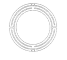
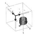
実施例1では、カーボン基材Aを用いて、図1に示す外径530mmで断面がT字形状の多重リング型ヒーターを作製した。この実施例1では、図2に示すように、ヒーターの中心軸方向(点線)と基材の電気抵抗率の異方性方向(Z軸)が一致するように材料取りを行った。このときの25℃における抵抗値は、0.244Ωであった。また、作製したカーボンヒーターには、1800℃、50Paの条件で、BCl3とNH3ガスを原料ガスとして200μmのPBN膜を被覆した。
<Example 1>
In Example 1, the carbon base material A was used to produce a multiple ring heater having an outer diameter of 530 mm and a T-shaped cross section shown in FIG. In Example 1, as shown in FIG. 2, the material was taken so that the central axis direction of the heater (dotted line) and the anisotropic direction of the electrical resistivity of the base material (Z axis) coincided. At this time, the resistance value at 25 ° C. was 0.244Ω. The produced carbon heater was covered with a 200 μm PBN film using BCl 3 and NH 3 gas as source gases under the conditions of 1800 ° C. and 50 Pa.
本発明の製造方法では、ヒーターの中心軸方向(点線)と基材の電気抵抗率の異方性方向(Z軸)が一致するように材料取りを行ってカーボンヒーターを製造する。具体的には、まず、大型の基材ブロックの抵抗率を測定して、最も抵抗率の高くなる軸(Z軸)方向を確認するとともに、その軸に垂直な面内方向の抵抗率がほぼ一定であることを確認した。また、互いに直交するように3軸(X軸、Y軸、Z軸)方向を決定した。そして、大型の基材ブロックから、おおよそ作製するヒーターの大きさとなるように基材ブロックを切り出した。このとき、作製するヒーターの中心軸方向と基材の電気抵抗率の異方性方向(Z軸)が一致するように切り出した。 In the manufacturing method of the present invention, the carbon heater is manufactured by taking the material so that the central axis direction (dotted line) of the heater coincides with the anisotropic direction (Z axis) of the electrical resistivity of the substrate. Specifically, first, the resistivity of a large-sized substrate block is measured to confirm the axis (Z-axis) direction where the resistivity is highest, and the resistivity in the in-plane direction perpendicular to the axis is almost equal. Confirmed to be constant. Further, the directions of the three axes (X axis, Y axis, Z axis) were determined so as to be orthogonal to each other. And the base-material block was cut out from the large-sized base-material block so that it might become the magnitude | size of the heater to produce approximately. At this time, it cut out so that the center axis direction of the heater to produce and the anisotropic direction (Z-axis) of the electrical resistivity of a base material might correspond.
続いて、旋盤を用いて円盤形状(実施例2〜4では円筒形状)となるように加工を施し、さらにマシニングセンターを用いて細部の加工を施した。ヒーター形状に加工されたカーボン基材には、サンドブラスト加工を施し、表面粗さがRa値で2.0〜10.0μmとなるようにした。そして、作製したカーボンヒーターの表面をエアーガンでクリーニングし、必要に応じ、純水で超音波洗浄・乾燥処理し、4端子法により抵抗値を確認した。 Then, it processed so that it might become a disk shape (cylindrical shape in Examples 2-4) using the lathe, and also processed the detail using the machining center. The carbon base material processed into a heater shape was subjected to sandblasting so that the surface roughness was 2.0 to 10.0 μm in terms of Ra value. Then, the surface of the produced carbon heater was cleaned with an air gun, and ultrasonically cleaned and dried with pure water as necessary, and the resistance value was confirmed by a four-terminal method.
次に、このPBN製耐熱被膜を有したヒーターを真空引き可能なチャンバーに設置し、加熱試験を実施した。図4に示す装置で放射温度計を用いて表面温度を観察したところ、端子部および回路が分岐もしくは合流する部分および折返し部分の温度の高低差が△5℃(平均温度1400℃)程度と計測された。 Next, a heater having this PBN heat-resistant coating was placed in a vacuum evacuable chamber, and a heating test was performed. When the surface temperature was observed using a radiation thermometer with the apparatus shown in FIG. 4, the temperature difference between the terminal portion and the portion where the circuit branches or merges and the folded portion was measured to be about Δ5 ° C. (average temperature 1400 ° C.). It was done.
〈比較例1〉
比較例1では、カーボン基材Aを用いて、実施例1と同型状のリング型ヒーターを作製した。この比較例1では、図3に示すように、ヒーターの中心軸方向(点線)は、Y軸方向と一致するように材料取りを行った。このときの25℃における抵抗値は、0.285Ωであった。これは、X方向とZ方向での抵抗率の異方性に起因するものであると判断される。また、作製したカーボンヒーターには、1450℃、30Paの条件で、SiCl4とCH4ガスを原料ガスとして150μmのSiC膜を被覆した。
<Comparative example 1>
In Comparative Example 1, a ring-type heater having the same shape as in Example 1 was produced using the carbon substrate A. In Comparative Example 1, as shown in FIG. 3, the material was taken so that the central axis direction (dotted line) of the heater coincided with the Y-axis direction. At this time, the resistance value at 25 ° C. was 0.285Ω. This is determined to be caused by the anisotropy of resistivity in the X direction and the Z direction. The produced carbon heater was coated with a 150 μm SiC film using SiCl 4 and CH 4 gas as source gases under the conditions of 1450 ° C. and 30 Pa.
次に、このSiC製耐熱被膜を有したヒーターを実施例1と同様に、真空引き可能なチャンバーに設置し加熱試験を実施した。そして、放射温度計で表面温度を観察したところ、通電方向がX方向となる部分で1392℃、Z方向となる部分で1418℃となり、発熱温度に大きな差異が見られた。これは、断面積が同じでも、単位長さ当たりの抵抗値が異なることによるジュール熱の発生差異が生じたものと判断される。 Next, a heater having this SiC heat-resistant coating was installed in a chamber that can be evacuated in the same manner as in Example 1, and a heating test was performed. Then, when the surface temperature was observed with a radiation thermometer, it was 1392 ° C. in the portion where the energizing direction was the X direction and 1418 ° C. in the portion where the energizing direction was the Z direction. It is determined that the difference in generation of Joule heat was caused by the difference in resistance value per unit length even though the cross-sectional areas were the same.
〈実施例2〉
実施例2では、カーボン基材Bを用いて、円筒部外径100mmで発熱部高さが65mmの略円筒形状のヒーターを作製した。この実施例2では、図5に示すように、ヒーターの中心軸方向(点線)と基材の電気抵抗率の異方性方向(Z軸)が一致するように材料取りを行った。このときの25℃における抵抗値は、0.521Ωであった。また、作製したカーボンヒーターには、1000℃、50Paの条件で、TaCl5とCH4ガスを原料ガスとして50μmのTaC膜を被覆した。
<Example 2>
In Example 2, a substantially cylindrical heater having a cylindrical part outer diameter of 100 mm and a heat generating part height of 65 mm was produced using the carbon base material B. In Example 2, as shown in FIG. 5, the material was taken so that the central axis direction of the heater (dotted line) and the anisotropic direction of the electrical resistivity of the base material (Z axis) coincided. At this time, the resistance value at 25 ° C. was 0.521Ω. The produced carbon heater was covered with a TaC film of 50 μm using TaCl 5 and CH 4 gas as source gases at 1000 ° C. and 50 Pa.
次に、このTaC製耐熱被膜を有したヒーターを実施例1と同様に、真空引き可能なチャンバーに設置し加熱試験を実施した。そして、放射温度計を用いて表面温度を観察したところ、全周に渡って直線状の通電部は1450℃±2°程度と良好な温度分布であり、通電回路の折返し部位でも異常な発熱は見られなかった。 Next, the heater having the TaC heat-resistant coating was installed in a vacuum-pumpable chamber in the same manner as in Example 1 to conduct a heating test. Then, when the surface temperature was observed using a radiation thermometer, the linear energization part had a good temperature distribution of about 1450 ° C. ± 2 ° over the entire circumference, and abnormal heat generation was observed even at the folded part of the energization circuit. I couldn't see it.
〈比較例2〉
比較例2では、カーボン基材Bを用いて、実施例2と同形状のヒーターを作製した。この比較例2では、図6に示すように、ヒーターの中心軸方向(点線)は、Y軸方向と一致するように材料取りを行った。このとき、比較例2の主たる通電方向はY軸方向であり、実施例2の主たる通電方向であるZ軸よりも電気抵抗率が小さい。そのため、比較例2と実施例2のヒーターの抵抗値を合わせる目的で、比較例2では内径を大きくして、断面積を小さくした。また、作製したカーボンヒーターには、1000℃、50Paの条件で、TaCl5とCH4ガスを原料ガスとして50μmのTaC膜を被覆した。
<Comparative example 2>
In Comparative Example 2, a heater having the same shape as in Example 2 was produced using the carbon base material B. In Comparative Example 2, as shown in FIG. 6, the material was taken so that the central axis direction (dotted line) of the heater coincided with the Y-axis direction. At this time, the main energization direction of Comparative Example 2 is the Y-axis direction, and the electrical resistivity is smaller than that of the Z-axis, which is the main energization direction of Example 2. Therefore, in order to match the resistance values of the heaters of Comparative Example 2 and Example 2, in Comparative Example 2, the inner diameter was increased and the cross-sectional area was decreased. The produced carbon heater was covered with a TaC film of 50 μm using TaCl 5 and CH 4 gas as source gases at 1000 ° C. and 50 Pa.
次に、このTaC製耐熱被膜を有したヒーターを実施例1と同様に、真空引き可能なチャンバーに設置し加熱試験を実施した。そして、放射温度計を用いて表面温度を観察したところ、通電回路の折返し部位と端子部近傍以外では、1400℃±3℃程度と良好な温度分布が得られた。しかしながら、通電回路の折返し部位では異常な発熱が見られ、Z軸方向の折返し部位では1440℃となり、X軸方向の折返し部位では1402℃となった。 Next, the heater having the TaC heat-resistant coating was installed in a vacuum-pumpable chamber in the same manner as in Example 1 to conduct a heating test. Then, when the surface temperature was observed using a radiation thermometer, a good temperature distribution of about 1400 ° C. ± 3 ° C. was obtained except in the vicinity of the folded portion of the energizing circuit and the terminal portion. However, abnormal heat generation was observed at the folded portion of the energization circuit, and the temperature was 1440 ° C. at the folded portion in the Z-axis direction and 1402 ° C. at the folded portion in the X-axis direction.
〈実施例3〉
実施例3では、カーボン基材Dを用いて、円筒部外径200mmで発熱部幅が260mmの略円筒形状の螺旋ヒーターを作製した。この実施例3では、図7に示すように、ヒーターの中心軸方向(点線)と基材の電気抵抗率の異方性方向(Z軸)が一致するように材料取りを行った。このときの25℃における抵抗値は、0.209Ωであった。また、作製したカーボンヒーターには、1600℃、100Paの条件で、CH4ガスを原料ガスとして50μmのPG膜を被覆した。
<Example 3>
In Example 3, a substantially cylindrical spiral heater having a cylindrical part outer diameter of 200 mm and a heating part width of 260 mm was produced using the carbon substrate D. In Example 3, as shown in FIG. 7, the material was taken so that the central axis direction of the heater (dotted line) and the anisotropic direction of the electrical resistivity of the base material (Z axis) coincided. At this time, the resistance value at 25 ° C. was 0.209Ω. The produced carbon heater was coated with a 50 μm PG film using CH 4 gas as a source gas under the conditions of 1600 ° C. and 100 Pa.
次に、このPG製耐熱被膜を有したヒーターを実施例1と同様に、真空引き可能なチャンバーに設置し加熱試験を実施した。そして、放射温度計を用いて表面温度を観察したところ、螺旋状の通電部は1600℃±5℃程度と良好な温度分布が得られた。 Next, the heater having the PG heat-resistant coating was installed in a vacuum-pumpable chamber in the same manner as in Example 1, and a heating test was performed. Then, when the surface temperature was observed using a radiation thermometer, a favorable temperature distribution of about 1600 ° C. ± 5 ° C. was obtained for the spiral energized portion.
〈比較例3〉
比較例3では、カーボン基材D用いて、実施例3と同形状の螺旋ヒーターを作製した。この比較例3では、図8に示すように、ヒーターの中心軸方向(点線)は、Y軸方向と一致するように材料取りを行った。このときの25℃における抵抗値は、0.238Ωであった。また、作製したカーボンヒーターには、1600℃、100Paの条件で、CH4ガスを原料ガスとして50μmのPG膜を被覆した。
<Comparative Example 3>
In Comparative Example 3, a helical heater having the same shape as in Example 3 was produced using the carbon substrate D. In Comparative Example 3, as shown in FIG. 8, the material was taken so that the central axis direction (dotted line) of the heater coincided with the Y-axis direction. At this time, the resistance value at 25 ° C. was 0.238Ω. The produced carbon heater was coated with a 50 μm PG film using CH 4 gas as a source gas under the conditions of 1600 ° C. and 100 Pa.
次に、このPG製耐熱被膜を有したヒーターを、実施例1と同様に、真空引き可能なチャンバーに設置し加熱試験を実施した。そして、放射温度計を用いて表面温度を観察したところ、螺旋状の通電部は1570〜1630℃程度の温度差が観察された。これは、主とする通電方向がX軸方向となるかZ軸方向となるかによって、断面積が同じでも単位長さ当たりの抵抗値が異なるため、ジュール熱の発生差異が生じたことが原因と判断される。 Next, the heater having this PG heat-resistant coating was placed in a vacuum-pullable chamber in the same manner as in Example 1 to conduct a heating test. And when the surface temperature was observed using the radiation thermometer, the temperature difference of about 1570-1630 degreeC was observed by the spiral electricity supply part. This is because the resistance value per unit length is different even if the cross-sectional area is the same, depending on whether the main energization direction is the X-axis direction or the Z-axis direction. It is judged.
〈実施例4〉
実施例4では、カーボン基材E用いて、円筒部外径120mmで発熱部高さが65mmの略円筒形状の二重螺旋ヒーターを作製した。この実施例4では、図9に示すように、ヒーターの中心軸方向(点線)と基材の電気抵抗率の異方性方向(Z軸)が一致するように材料取りを行った。このときの25℃における抵抗値は0.409Ωであった。また、作製したカーボンヒーターには、1800℃、100Paの条件で、BCl3ガスおよびNH3を原料ガスとして300μmのPBN膜を被覆した。
<Example 4>
In Example 4, a substantially cylindrical double spiral heater having a cylindrical part outer diameter of 120 mm and a heating part height of 65 mm was produced using the carbon substrate E. In Example 4, as shown in FIG. 9, the material was taken so that the central axis direction (dotted line) of the heater and the anisotropic direction (Z axis) of the electrical resistivity of the substrate coincided. The resistance value at 25 ° C. at this time was 0.409Ω. The produced carbon heater was coated with a 300 μm PBN film using BCl 3 gas and NH 3 as source gases under the conditions of 1800 ° C. and 100 Pa.
次に、このPBN製耐熱被膜を有したヒーターを実施例1と同様に、真空引き可能なチャンバーに設置し加熱試験を実施した。そして、放射温度計を用いて表面温度を観察したところ、二重螺旋状の通電部は1600℃±5℃程度と良好な温度分布部が得られた。また、Z軸方向の段差部の回路内側では高めの発熱が観察され、外側では低めの温度が観察された。 Next, the heater having the PBN heat-resistant film was installed in a vacuum evacuable chamber in the same manner as in Example 1, and a heating test was performed. Then, when the surface temperature was observed using a radiation thermometer, a good temperature distribution portion of about 1600 ° C. ± 5 ° C. was obtained for the double spiral energized portion. Further, higher heat generation was observed inside the circuit of the step portion in the Z-axis direction, and a lower temperature was observed outside.
1:カーボン基材
2:実施例1および比較例1のカーボンヒーター
3:実施例1および比較例1のカーボンヒーターの中心軸または回転軸
4:実施例2および比較例2のカーボンヒーター
5:実施例2および比較例2のカーボンヒーターの中心軸または回転軸
6:実施例2および比較例2のカーボンヒーターの主たる発熱部
7:実施例2および比較例2のカーボンヒーターの通電回路の折返し部
8:実施例2および比較例2のカーボンヒーターの端子部
9:実施例3および比較例3のカーボンヒーター
10:実施例3および比較例3のカーボンヒーターの中心軸または螺旋軸
11:実施例3および比較例3のカーボンヒーターの主たる発熱部
12:実施例3および比較例3のカーボンヒーターの端子部
13:実施例4のカーボンヒーター
14:実施例4のカーボンヒーターの中心軸または回転軸
15:実施例4のカーボンヒーターの主たる発熱部
16:実施例4のカーボンヒーターの通電回路の折返し部
17:実施例4のカーボンヒーターの通電回路の接続部
18:実施例4のカーボンヒーターの端子部
1: Carbon base material 2: Carbon heater of Example 1 and Comparative Example 1 3: Center axis or rotating shaft of the carbon heater of Example 1 and Comparative Example 1: Carbon heater 5 of Example 2 and Comparative Example 2: Implementation Central axis or rotating shaft 6 of the carbon heaters of Example 2 and Comparative Example 2: Main heat generating part 7 of the carbon heaters of Example 2 and Comparative Example 2: Turn-up part 8 of the energization circuit of the carbon heaters of Example 2 and Comparative Example 2 : Terminal part 9 of carbon heater of Example 2 and Comparative Example 2: Carbon heater 10 of Example 3 and Comparative Example 3: Center axis or helical shaft 11 of the carbon heater of Example 3 and Comparative Example 3: Example 3 and Main heat generating part 12 of the carbon heater of Comparative Example 3: Example 3 and terminal part 13 of the carbon heater of Comparative Example 3: Carbon heater 14 of Example 4 Central axis or rotating shaft 15 of the carbon heater of the fourth embodiment: Main heat generating portion 16 of the carbon heater of the fourth embodiment: Turn-up portion 17 of the energizing circuit of the carbon heater of the fourth embodiment 17: of the energizing circuit of the carbon heater of the fourth embodiment Connection part 18: Terminal part of the carbon heater of Example 4
次に、このTaC製耐熱被膜を有したヒーターを実施例1と同様に、真空引き可能なチャンバーに設置し加熱試験を実施した。そして、放射温度計を用いて表面温度を観察したところ、全周に渡って直線状の通電部は1450℃±2℃程度と良好な温度分布であり、通電回路の折返し部位でも異常な発熱は見られなかった。 Next, the heater having the TaC heat-resistant coating was installed in a vacuum-pumpable chamber in the same manner as in Example 1 to conduct a heating test. Then, when the surface temperature was observed using a radiation thermometer, the linear energization part had a good temperature distribution of about 1450 ° C ± 2 ° C over the entire circumference, and abnormal heat generation was also observed at the folded part of the energization circuit. I couldn't see it.
〈実施例3〉
実施例3では、カーボン基材Dを用いて、円筒部外径200mmで発熱部幅が260mmの略円筒形状の螺旋ヒーターを作製した。この実施例3では、図8に示すように、ヒーターの中心軸方向(点線)と基材の電気抵抗率の異方性方向(Z軸)が一致するように材料取りを行った。このときの25℃における抵抗値は、0.209Ωであった。また、作製したカーボンヒーターには、1600℃、100Paの条件で、CH4ガスを原料ガスとして50μmのPG膜を被覆した。
<Example 3>
In Example 3, a substantially cylindrical spiral heater having a cylindrical part outer diameter of 200 mm and a heating part width of 260 mm was produced using the carbon substrate D. In Example 3, as shown in FIG. 8 , the material was taken so that the central axis direction of the heater (dotted line) and the anisotropic direction of the electrical resistivity of the base material (Z axis) coincided. At this time, the resistance value at 25 ° C. was 0.209Ω. The produced carbon heater was coated with a 50 μm PG film using CH 4 gas as a source gas under the conditions of 1600 ° C. and 100 Pa.
〈比較例3〉
比較例3では、カーボン基材D用いて、実施例3と同形状の螺旋ヒーターを作製した。この比較例3では、図9に示すように、ヒーターの中心軸方向(点線)は、Y軸方向と一致するように材料取りを行った。このときの25℃における抵抗値は、0.238Ωであった。また、作製したカーボンヒーターには、1600℃、100Paの条件で、CH4ガスを原料ガスとして50μmのPG膜を被覆した。
<Comparative Example 3>
In Comparative Example 3, a helical heater having the same shape as in Example 3 was produced using the carbon substrate D. In Comparative Example 3, as shown in FIG. 9 , the material was taken so that the central axis direction (dotted line) of the heater coincided with the Y-axis direction. At this time, the resistance value at 25 ° C. was 0.238Ω. The produced carbon heater was coated with a 50 μm PG film using CH 4 gas as a source gas under the conditions of 1600 ° C. and 100 Pa.
〈実施例4〉
実施例4では、カーボン基材E用いて、円筒部外径120mmで発熱部高さが65mmの略円筒形状の二重螺旋ヒーターを作製した。この実施例4では、図11に示すように、ヒーターの中心軸方向(点線)と基材の電気抵抗率の異方性方向(Z軸)が一致するように材料取りを行った。このときの25℃における抵抗値は0.409Ωであった。また、作製したカーボンヒーターには、1800℃、100Paの条件で、BCl3ガスおよびNH3を原料ガスとして300μmのPBN膜を被覆した。
<Example 4>
In Example 4, a substantially cylindrical double spiral heater having a cylindrical part outer diameter of 120 mm and a heating part height of 65 mm was produced using the carbon substrate E. In Example 4, as shown in FIG. 11 , the material was taken so that the central axis direction of the heater (dotted line) and the anisotropic direction of the electrical resistivity of the base material (Z axis) coincided. The resistance value at 25 ° C. at this time was 0.409Ω. The produced carbon heater was coated with a 300 μm PBN film using BCl 3 gas and NH 3 as source gases under the conditions of 1800 ° C. and 100 Pa.
次に、このPBN製耐熱被膜を有したヒーターを実施例1と同様に、真空引き可能なチャンバーに設置し加熱試験を実施した。そして、放射温度計を用いて表面温度を観察したところ、二重螺旋状の通電部は1600℃±5℃程度と良好な温度分布が得られた。また、Z軸方向の段差部の回路内側では高めの発熱が観察され、外側では低めの温度が観察された。 Next, the heater having the PBN heat-resistant film was installed in a vacuum evacuable chamber in the same manner as in Example 1, and a heating test was performed. Then, when the surface temperature was observed using a radiation thermometer, a good temperature distribution of about 1600 ° C. ± 5 ° C. was obtained for the double spiral energized part. Further, higher heat generation was observed inside the circuit of the step portion in the Z-axis direction, and a lower temperature was observed outside.
Claims (14)
A method of manufacturing a carbon heater having a carbon base material having substantially 2D orthogonal anisotropy in terms of electrical resistivity, and having a main heat generating portion having a rotational symmetry or a helical symmetry. A method for producing a carbon heater, characterized in that the material is taken so that the anisotropic direction of the rate substantially coincides with the rotation axis direction or the helical axis direction of the carbon heater.
Priority Applications (2)
| Application Number | Priority Date | Filing Date | Title |
|---|---|---|---|
| JP2015238068A JP6436896B2 (en) | 2015-12-04 | 2015-12-04 | Carbon heater and method of manufacturing carbon heater |
| TW105139645A TWI636702B (en) | 2015-12-04 | 2016-12-01 | Carbon heater and method for manufacturing carbon heater |
Applications Claiming Priority (1)
| Application Number | Priority Date | Filing Date | Title |
|---|---|---|---|
| JP2015238068A JP6436896B2 (en) | 2015-12-04 | 2015-12-04 | Carbon heater and method of manufacturing carbon heater |
Publications (2)
| Publication Number | Publication Date |
|---|---|
| JP2017103190A true JP2017103190A (en) | 2017-06-08 |
| JP6436896B2 JP6436896B2 (en) | 2018-12-12 |
Family
ID=59017564
Family Applications (1)
| Application Number | Title | Priority Date | Filing Date |
|---|---|---|---|
| JP2015238068A Active JP6436896B2 (en) | 2015-12-04 | 2015-12-04 | Carbon heater and method of manufacturing carbon heater |
Country Status (2)
| Country | Link |
|---|---|
| JP (1) | JP6436896B2 (en) |
| TW (1) | TWI636702B (en) |
Cited By (1)
| Publication number | Priority date | Publication date | Assignee | Title |
|---|---|---|---|---|
| WO2019078036A1 (en) * | 2017-10-18 | 2019-04-25 | 新日本テクノカーボン株式会社 | SUSCEPTOR |
Families Citing this family (1)
| Publication number | Priority date | Publication date | Assignee | Title |
|---|---|---|---|---|
| CN113261706B (en) * | 2021-06-02 | 2024-11-19 | 佛山天为环保科技有限公司 | Electronic atomizer |
Citations (5)
| Publication number | Priority date | Publication date | Assignee | Title |
|---|---|---|---|---|
| JPH07296955A (en) * | 1994-04-22 | 1995-11-10 | Nippon Steel Corp | Carbon heater |
| US20050120547A1 (en) * | 2002-02-27 | 2005-06-09 | Christoph Bommier | Resistor made from carbonaceous material |
| JP2010040718A (en) * | 2008-08-04 | 2010-02-18 | Soken Kogyo Kk | Heater, substrate heating apparatus and crystal growth apparatus using them |
| JP2013220954A (en) * | 2012-04-13 | 2013-10-28 | Ibiden Co Ltd | Graphite heater |
| JP2016525270A (en) * | 2013-07-15 | 2016-08-22 | モーメンティブ・パフォーマンス・マテリアルズ・インク | Structure of coated graphite heater |
Family Cites Families (3)
| Publication number | Priority date | Publication date | Assignee | Title |
|---|---|---|---|---|
| US5444327A (en) * | 1993-06-30 | 1995-08-22 | Varian Associates, Inc. | Anisotropic pyrolytic graphite heater |
| JP2007273618A (en) * | 2006-03-30 | 2007-10-18 | Toshiba Corp | Resistance change memory device |
| EP2896065A1 (en) * | 2012-08-27 | 2015-07-22 | Oerlikon Advanced Technologies AG | Processing arrangement with temperature conditioning arrangement and method of processing a substrate |
-
2015
- 2015-12-04 JP JP2015238068A patent/JP6436896B2/en active Active
-
2016
- 2016-12-01 TW TW105139645A patent/TWI636702B/en active
Patent Citations (5)
| Publication number | Priority date | Publication date | Assignee | Title |
|---|---|---|---|---|
| JPH07296955A (en) * | 1994-04-22 | 1995-11-10 | Nippon Steel Corp | Carbon heater |
| US20050120547A1 (en) * | 2002-02-27 | 2005-06-09 | Christoph Bommier | Resistor made from carbonaceous material |
| JP2010040718A (en) * | 2008-08-04 | 2010-02-18 | Soken Kogyo Kk | Heater, substrate heating apparatus and crystal growth apparatus using them |
| JP2013220954A (en) * | 2012-04-13 | 2013-10-28 | Ibiden Co Ltd | Graphite heater |
| JP2016525270A (en) * | 2013-07-15 | 2016-08-22 | モーメンティブ・パフォーマンス・マテリアルズ・インク | Structure of coated graphite heater |
Cited By (4)
| Publication number | Priority date | Publication date | Assignee | Title |
|---|---|---|---|---|
| WO2019078036A1 (en) * | 2017-10-18 | 2019-04-25 | 新日本テクノカーボン株式会社 | SUSCEPTOR |
| JPWO2019078036A1 (en) * | 2017-10-18 | 2019-12-19 | 新日本テクノカーボン株式会社 | Susceptor |
| KR20200013796A (en) * | 2017-10-18 | 2020-02-07 | 신닛뽄테크노카본 가부시키가이샤 | Susceptor |
| KR102088493B1 (en) | 2017-10-18 | 2020-03-12 | 신닛뽄테크노카본 가부시키가이샤 | Susceptor |
Also Published As
| Publication number | Publication date |
|---|---|
| TWI636702B (en) | 2018-09-21 |
| TW201722197A (en) | 2017-06-16 |
| JP6436896B2 (en) | 2018-12-12 |
Similar Documents
| Publication | Publication Date | Title |
|---|---|---|
| JP5680664B2 (en) | Heating device | |
| JP5737547B2 (en) | Method for producing silicon carbide-coated graphite particles and silicon carbide-coated graphite particles | |
| JP5524213B2 (en) | Wafer processing apparatus with adjustable electrical resistivity | |
| CN103408315A (en) | Three-dimensional mesophase pitch-based carbon/carbon composite material with high heat conductivity and preparation technology thereof | |
| JPWO2014123036A1 (en) | Silicon carbide-tantalum carbide composite and susceptor | |
| JP6714616B2 (en) | Carbon nanotube bonding sheet and method for manufacturing carbon nanotube bonding sheet | |
| WO2011027757A1 (en) | Ceramic carbon composite material, method for producing ceramic carbon composite material, ceramic-coated ceramic carbon composite material, and method for producing ceramic-coated ceramic carbon composite material | |
| CN102659452B (en) | Carbon/carbon composite super high temperature anti-oxidation coating and preparation method thereof | |
| US20130269601A1 (en) | Graphite heater | |
| TWI728327B (en) | Composite sintered body, semiconductor manufacturing apparatus member, and method of manufacturing composite sintered body | |
| TW201904916A (en) | Aluminum nitride sintered body and member for semiconductor manufacturing apparatus including the same | |
| JP6436896B2 (en) | Carbon heater and method of manufacturing carbon heater | |
| CN102674892A (en) | Carbon/carbon composite ultrahigh temperature anti-oxidation coating and preparation process thereof | |
| JP6621971B2 (en) | Susceptor | |
| CN108545733A (en) | A kind of preparation method of graphite film and products thereof and purposes | |
| CN104302021A (en) | Heating unit used for electrical heating and preparation technology of heating unit | |
| CN103408326A (en) | Preparation method of Si-Mo-Cr oxidation resistant coating on surface of C/C composite material | |
| CN103050357B (en) | Rotary anode and the method for manufacturing the matrix of rotary anode | |
| KR20120078270A (en) | Susceptor using low thermal expansion composite materials and method for manufacturing esc component | |
| US20110064891A1 (en) | Methods of rapidly densifying complex-shaped, asymmetrical porous structures | |
| CN104926349A (en) | Method and depositing furnace for rapidly depositing and preparing C/C composite material by direct heating method | |
| JP6652770B2 (en) | Method for producing separator for polymer electrolyte fuel cell | |
| JP2016017196A (en) | Ti OXIDE SPUTTERING TARGET AND METHOD FOR MANUFACTURING THE SAME | |
| CN106892684B (en) | A kind of preparation method of ZrC coating on the surface of C/C composite material | |
| JP5854512B2 (en) | Method for producing pyrolytic boron nitride-coated carbonaceous substrate |
Legal Events
| Date | Code | Title | Description |
|---|---|---|---|
| A621 | Written request for application examination |
Free format text: JAPANESE INTERMEDIATE CODE: A621 Effective date: 20171121 |
|
| A131 | Notification of reasons for refusal |
Free format text: JAPANESE INTERMEDIATE CODE: A131 Effective date: 20180912 |
|
| A977 | Report on retrieval |
Free format text: JAPANESE INTERMEDIATE CODE: A971007 Effective date: 20180912 |
|
| A521 | Request for written amendment filed |
Free format text: JAPANESE INTERMEDIATE CODE: A523 Effective date: 20181105 |
|
| TRDD | Decision of grant or rejection written | ||
| A01 | Written decision to grant a patent or to grant a registration (utility model) |
Free format text: JAPANESE INTERMEDIATE CODE: A01 Effective date: 20181113 |
|
| A61 | First payment of annual fees (during grant procedure) |
Free format text: JAPANESE INTERMEDIATE CODE: A61 Effective date: 20181113 |
|
| R150 | Certificate of patent or registration of utility model |
Ref document number: 6436896 Country of ref document: JP Free format text: JAPANESE INTERMEDIATE CODE: R150 |