JP2017103191A - Manufacturing method of ceramic discharge container - Google Patents
Manufacturing method of ceramic discharge container Download PDFInfo
- Publication number
- JP2017103191A JP2017103191A JP2015238110A JP2015238110A JP2017103191A JP 2017103191 A JP2017103191 A JP 2017103191A JP 2015238110 A JP2015238110 A JP 2015238110A JP 2015238110 A JP2015238110 A JP 2015238110A JP 2017103191 A JP2017103191 A JP 2017103191A
- Authority
- JP
- Japan
- Prior art keywords
- hole
- calcined body
- tube portion
- discharge vessel
- wheel
- Prior art date
- Legal status (The legal status is an assumption and is not a legal conclusion. Google has not performed a legal analysis and makes no representation as to the accuracy of the status listed.)
- Pending
Links
Images







Landscapes
- Manufacture Of Electron Tubes, Discharge Lamp Vessels, Lead-In Wires, And The Like (AREA)
- Vessels And Coating Films For Discharge Lamps (AREA)
Abstract
【課題】仮焼体の細管部の穴あけ加工において、細管部(キャピラリ)の加工孔の中心軸線を放電容器の中心軸線に整合させることできる放電容器の製造技術を提供する。【解決手段】セラミックス製の放電容器の製造方法において、アルミナ原料、助剤、及び、水を混合して生成したスラリーから成形体を形成する成形体形成ステップと、前記成形体を仮焼して原孔を有する細管部を備えた仮焼体を形成する仮焼ステップと、前記仮焼体の細管部の原孔にキャピラリの穴あけ加工によって加工孔を形成する穴あけ加工ステップと、前記キャピラリの穴あけ加工がされた仮焼体を本焼成する本焼成ステップと、を有し、前記穴あけ加工ステップでは、先端にリーマ部を備えたホイールを用いて前記仮焼体の細管部の原孔に加工孔を形成する。【選択図】図3BDisclosed is a discharge vessel manufacturing technique capable of aligning a central axis of a processing hole of a thin tube portion (capillary) with a central axis of a discharge vessel in drilling a thin tube portion of a calcined body. In a method of manufacturing a ceramic discharge vessel, a molded body forming step of forming a molded body from a slurry formed by mixing alumina raw material, an auxiliary agent, and water, and calcining the molded body. A calcining step for forming a calcined body having a thin tube portion having a raw hole; a boring step for forming a processing hole in the raw hole of the thin tube portion of the calcined body by drilling a capillary; and A main firing step of firing the calcined body that has been processed, and in the drilling step, a processing hole is formed in the original hole of the thin tube portion of the calcined body using a wheel having a reamer at the tip. Form. [Selection] Figure 3B
Description
本発明は、高圧放電ランプ用のセラミックス製の放電容器の製造技術に関し、特に、キャピラリの穴あけ加工方法に関する。 The present invention relates to a technology for manufacturing a ceramic discharge vessel for a high-pressure discharge lamp, and more particularly to a capillary drilling method.
近年、石英製の放電容器(発光管)の代わりに、透光性を有するセラミックス(以下、透光性セラミックス)製の放電容器に用いた高圧放電ランプが広く使用されている。透光性セラミックスは、石英と比較して耐熱性、耐食性に優れているため、これを用いた高圧放電ランプは、高効率及び高演色、更に長寿命など非常に優れた特性を得ることができる。 In recent years, high-pressure discharge lamps used in discharge containers made of translucent ceramics (hereinafter referred to as translucent ceramics) have been widely used instead of quartz discharge containers (arc tubes). Since translucent ceramics are superior in heat resistance and corrosion resistance compared to quartz, a high-pressure discharge lamp using the ceramics can obtain very excellent characteristics such as high efficiency, high color rendering, and long life. .
セラミックス製の放電容器の製造法の一つとして、排泥鋳込み法(泥漿鋳込み方法)が用いられる。排泥鋳込み法では、石膏製の型にアルミナを含むスラリーを充填し、所定の時間保持する。石膏にスラリーの水分が吸収され、型の内面にスラリーの固形分が着肉する。次に、排泥(スラリーの除去)を行うと、型の内面に着肉したスラリーが残る。これを乾燥し、離型し、得られた成形体を仮焼成し、仮焼体が得られる。次に、仮焼体に対してキャピラリの穴あけ加工を行う。キャピラリの穴あけ加工では、仮焼体の細管部(キャピラリ)に形成されている孔の内面を削って新たな孔を形成する。最後に本焼成することによりセラミックス製の放電容器が得られる。尚、本明細書では、適宜、仮焼体の細管部(キャピラリ)に形成されている孔を「原孔」と称し、キャピラリの穴あけ加工によって新たに形成された孔を「加工孔」と称して、両者の混同を回避する。 As one method for producing a ceramic discharge vessel, a mud casting method (a mud casting method) is used. In the sludge casting method, a gypsum mold is filled with a slurry containing alumina and held for a predetermined time. The water content of the slurry is absorbed by the gypsum, and the solid content of the slurry deposits on the inner surface of the mold. Next, when the mud is removed (removal of the slurry), the slurried slurry remains on the inner surface of the mold. This is dried, released, and the obtained molded body is calcined to obtain a calcined body. Next, the capillary is drilled in the calcined body. In the capillary drilling process, a new hole is formed by scraping the inner surface of the hole formed in the narrow tube portion (capillary) of the calcined body. Finally, a ceramic discharge vessel is obtained by final firing. In the present specification, holes formed in the narrow tube portion (capillary) of the calcined body are appropriately referred to as “original holes”, and holes newly formed by drilling a capillary are referred to as “process holes”. To avoid confusion between the two.
仮焼体の細管部(キャピラリ)の原孔の中心軸線は、通常、仮焼体の中心軸線に対して僅かに偏芯している。そのため、次のキャピラリの穴あけ加工の工程において、仮焼体の細管部(キャピラリ)の原孔の内面を削る加工を行うと、形成された加工孔は依然として、仮焼体の中心軸線に対して偏芯している。即ち、従来の技術では、仮焼体の細管部の穴あけ加工の工程において、細管部(キャピラリ)の加工孔の中心軸線を放電容器の中心軸線に整合させることは困難である。 The central axis of the original hole of the thin tube portion (capillary) of the calcined body is usually slightly eccentric with respect to the central axis of the calcined body. Therefore, in the next step of drilling the capillary, when the inner surface of the original hole of the thin tube portion (capillary) of the calcined body is cut, the formed hole still remains in relation to the central axis of the calcined body. It is eccentric. That is, according to the conventional technique, it is difficult to align the center axis of the processing hole of the narrow tube portion (capillary) with the center axis of the discharge vessel in the step of drilling the thin tube portion of the calcined body.
本発明の目的は、仮焼体の細管部の穴あけ加工において、細管部(キャピラリ)の加工孔の中心軸線を放電容器の中心軸線に整合させることできる放電容器の製造技術を提供することにある。 An object of the present invention is to provide a discharge vessel manufacturing technique capable of aligning the center axis of a processing hole of a narrow tube portion (capillary) with the center axis of the discharge vessel in drilling a thin tube portion of a calcined body. .
本発明の実施形態によると、発光部と該発光部の両側に細管部を有するセラミックス製の放電容器の製造方法において、
アルミナ原料、助剤、及び、水を混合して生成したスラリーから成形体を形成する成形体形成ステップと、
前記成形体を仮焼して原孔を有する細管部を備えた仮焼体を形成する仮焼ステップと、
穴あけ工具であるホイールを用いて前記仮焼体の細管部の原孔に加工孔を形成する穴あけ加工ステップと、
前記キャピラリの穴あけ加工がされた仮焼体を本焼成する本焼成ステップと、
を有し、
前記ホイールは先端にリーマ部を備え、該リーマ部は、平坦な先端面と円筒状の外周面を有する。
According to an embodiment of the present invention, in a method for manufacturing a ceramic discharge vessel having a light emitting portion and thin tube portions on both sides of the light emitting portion,
A molded body forming step of forming a molded body from a slurry produced by mixing alumina raw material, auxiliary agent, and water,
Calcination step of calcining the molded body to form a calcined body having a narrow tube portion having original holes;
Drilling step of forming a processing hole in the original hole of the thin tube portion of the calcined body using a wheel that is a drilling tool;
A main firing step of subjecting the calcined body having been subjected to drilling of the capillary to main firing;
Have
The wheel includes a reamer at a tip, and the reamer has a flat tip and a cylindrical outer peripheral surface.
本発明の実施形態によると、前記放電容器の製造方法において、
前記穴あけ加工ステップは、前記ホイールを用いて前記仮焼体の細管部の原孔に下穴を形成する下穴加工ステップと、前記下穴加工ステップ後にドリルを用いて前記仮焼体の細管部の原孔に加工孔を形成する仕上げ加工ステップを含む、としてよい。
According to an embodiment of the present invention, in the method for manufacturing the discharge vessel,
The drilling step includes a pilot hole processing step of forming a pilot hole in the original hole of the thin tube portion of the calcined body using the wheel, and a narrow tube portion of the calcined body using a drill after the pilot hole processing step. A finishing step of forming a processing hole in the original hole.
本発明の実施形態によると、前記放電容器の製造方法において、
前記穴あけ加工ステップにおいて、前記ホイールの中心軸線H−Hは前記仮焼体の中心軸線O−Oに整合して配置され、且つ、前記仮焼体の細管部の原孔の中心軸線B−Bが、前記仮焼体の中心軸線O−Oに整合していない場合に、前記仮焼体の細管部には、前記細管部の原孔の中心軸線B−Bに整合しないが、前記仮焼体の中心軸線O−Oに整合した加工孔が形成される、としてよい。
According to an embodiment of the present invention, in the method for manufacturing the discharge vessel,
In the drilling step, the center axis HH of the wheel is arranged in alignment with the center axis OO of the calcined body, and the center axis BB of the original hole of the thin tube portion of the calcined body However, when it is not aligned with the center axis OO of the calcined body, the narrow tube portion of the calcined body does not align with the center axis BB of the original hole of the narrow tube portion, but the calcined body A processing hole aligned with the center axis OO of the body may be formed.
本発明の実施形態によると、前記放電容器の製造方法において、
前記リーマ部は、円筒状の表面に加工用砥粒を電着して形成したものである、としてよい。
According to an embodiment of the present invention, in the method for manufacturing the discharge vessel,
The reamer part may be formed by electrodeposition of processing abrasive grains on a cylindrical surface.
本発明の実施形態によると、前記放電容器の製造方法において、
前記ホイールは旋盤の回転部に装填されたチャックによって保持され、前記仮焼体は旋盤の固定部に装着された固定装置によって支持されている、としてよい。
According to an embodiment of the present invention, in the method for manufacturing the discharge vessel,
The wheel may be held by a chuck loaded on a rotating part of a lathe, and the calcined body may be supported by a fixing device attached to a fixing part of the lathe.
本発明の実施形態によると、前記放電容器の製造方法において、
前記成形体形成ステップにおいて、前記成形体は排泥鋳込み法によって形成される、としてよい。
According to an embodiment of the present invention, in the method for manufacturing the discharge vessel,
In the molded body forming step, the molded body may be formed by a waste mud casting method.
本発明の実施形態によると、アルミナ原料、助剤、及び、水を含むスラリーから形成された成形体を仮焼して得られた仮焼体を固定する固定装置と、前記仮焼体の細管部に孔を形成するためのホイールと、該ホイールを固定するチャックと、該チャックを回転させる回転機構と、を有する放電容器の製造装置において、
前記ホイールの中心軸線H−Hは前記仮焼体の中心軸線O−Oに整合して配置され、且つ、前記仮焼体の細管部の原孔の中心軸線B−Bが、前記仮焼体の中心軸線O−Oに整合していない場合に、前記前記仮焼体の細管部には、前記細管部の原孔の中心軸線B−Bに整合しないが、前記仮焼体の中心軸線O−Oに整合した加工孔が形成される。
According to an embodiment of the present invention, a fixing device for fixing a calcined body obtained by calcining a molded body formed from a slurry containing an alumina raw material, an auxiliary agent, and water, and a thin tube of the calcined body In a discharge vessel manufacturing apparatus having a wheel for forming a hole in a portion, a chuck for fixing the wheel, and a rotating mechanism for rotating the chuck,
The center axis HH of the wheel is arranged in alignment with the center axis OO of the calcined body, and the center axis BB of the original hole of the thin tube portion of the calcined body is the calcined body. In the case where it is not aligned with the central axis OO of the calcined body, the thin tube portion of the calcined body does not align with the central axis BB of the original hole of the thin tube portion, but the central axis O of the calcined body is not aligned. A machining hole aligned with -O is formed.
本発明の実施形態によると、前記放電容器の製造装置において、
前記ホイールは先端にリーマ部を備え、該リーマ部は、平坦な先端面と円筒状の外周面を有し、表面に加工用砥粒を電着して形成したものである、としてよい。
According to an embodiment of the present invention, in the discharge vessel manufacturing apparatus,
The wheel may be provided with a reamer at the tip, the reamer having a flat tip surface and a cylindrical outer peripheral surface, and formed by electrodeposition of processing abrasive grains on the surface.
本発明によれば、仮焼体の細管部の穴あけ加工において、細管部(キャピラリ)の加工孔の中心軸線を放電容器の中心軸線に整合させることできる放電容器の製造技術を提供することができる。 ADVANTAGE OF THE INVENTION According to this invention, the manufacturing technique of the discharge vessel which can match the center axis line of the processing hole of a thin tube part (capillary) with the center axis line of a discharge vessel can be provided in the drilling process of the thin tube part of a calcined body. .
以下、本発明に係る実施形態に関して、添付の図面を参照しながら詳細に説明する。なお、図中、同じ要素に対しては同じ参照符号を付して、重複した説明を省略する。 Hereinafter, embodiments according to the present invention will be described in detail with reference to the accompanying drawings. In the drawings, the same elements are denoted by the same reference numerals, and redundant description is omitted.
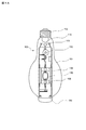
図1Aを参照して本実施形態に係るセラミックメタルハライドランプの一例を説明する。セラミックメタルハライドランプ100は、透光性外管111と、端部の口金112と、透光性外管111の内部のほぼ中央に配置されたセラミックス製の放電容器130を有する。透光性外管111の内部は圧力10Pa以下の高真空に保持される。本実施形態のセラミックメタルハライドランプ100は、図示のように口金112を上にして垂直に装着される。
An example of a ceramic metal halide lamp according to the present embodiment will be described with reference to FIG. 1A. The ceramic
放電容器130の周囲に透光性スリーブ108が設けられ、その外側に、金属製のフレーム109が設けられている。放電容器130の上側には、始動器110が設けられている。フレーム109の上端には、ゲッタ113が装着されている。
フレーム109は、下端のマウント支持板114と上端のステム115の導入線と接続しており、それによって、位置固定される。フレーム109は位置固定用の部材であると同時に電気的接続用の部材を兼ねており、図示しない外部給電システムからの電力をステム115の導入線を介して放電容器130に供給する。
A
The
図1Bを参照して放電容器130の構造を説明する。放電容器130は中央の発光部130Cとその両端の細管部130A、130Bを有する。細管部130A、130Bには、電流導入体120a、120bがそれぞれ装着されている。電流導入体120a、120bは、タングステン電極123、電流供給体122、及び、リード線121を有する。タングステン電極123は放電容器130の発光部130Cに配置されている。電流供給体122は、耐ハロゲン性中間材122aと導電性サーメット棒122bからなる。
The structure of the
リード線121は導電性サーメット棒122bの先端に接続されている。リード線121と導電性サーメット棒122bの接続部は補強材131によって囲まれている。リード線121は細管部130A、130Bの両端より突出している。
The
放電容器130の内部には、発光物質と、水銀および不活性ガスが封入されている。不活性ガスは例えば希ガスであるが本実施例ではアルゴンである。セラミックメタルハライドランプを点灯させると、放電容器130内における放電により、発光物質が加熱され、その一部が蒸発して放電により励起され、発光する。発光物質の残りの部分は、放電容器130の底部の最冷部に液相状態でプールされる。液相の発光物質の一部は蒸発し、放電容器130の内部を対流により循環し、底部の最冷部に戻る。ランプの点灯中はこのようなサイクルが繰り返される。
Inside the
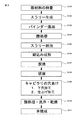
図2を参照して、本実施形態に係る高圧放電ランプ用のセラミックス製の放電容器の製造方法の例を説明する。先ず、ステップS101にて、原材料を秤量する。本実施形態では、原材料として、アルミナ粉末と助剤(酸化マグネシウム)を用いる。アルミナ粉末については後に詳細に説明する。ステップS102にて、スラリーを生成する。アルミナ粉末、助剤、及び、水を混合した原材料を容器に入れ、ボールミルにて10時間混合を行い、スラリーを生成する。ステップS103にて、バインダー添加を行う。スラリーを別の容器に移し、バインダーを加え、更に混合する。ステップS104にて、篩処理を行う。スラリーをナイロン製の篩にかけ、一定以上の大きさの粒子径のアルミナ塊を除去する。本実施形態では、目開き32μmの篩を用いた。ステップS105にて、スラリーの脱泡を行う。真空脱泡装置によりスラリーの気泡を除去する。ステップS106にて、鋳込み成形を行い、成形体を得る。先ず、スラリーを石膏型に充填し、所定の時間保持する。石膏にスラリーの水分が吸収され、型の内面にスラリーの固形分が着肉する。次に、排泥(スラリーの除去)を行うと、型の内面に着肉したスラリーが残る。これを乾燥し、離型し、成形体が得られる。 With reference to FIG. 2, the example of the manufacturing method of the ceramic discharge container for high pressure discharge lamps concerning this embodiment is demonstrated. First, in step S101, raw materials are weighed. In this embodiment, alumina powder and an auxiliary agent (magnesium oxide) are used as raw materials. The alumina powder will be described in detail later. In step S102, a slurry is generated. A raw material in which alumina powder, auxiliary agent, and water are mixed is put into a container, and mixed in a ball mill for 10 hours to produce a slurry. In step S103, a binder is added. Transfer the slurry to another container, add the binder and mix further. In step S104, sieve processing is performed. The slurry is passed through a nylon sieve to remove an alumina lump having a particle size of a certain size or more. In the present embodiment, a sieve having an opening of 32 μm is used. In step S105, the slurry is defoamed. The bubbles in the slurry are removed by a vacuum deaerator. In step S106, cast molding is performed to obtain a molded body. First, the slurry is filled into a gypsum mold and held for a predetermined time. The water content of the slurry is absorbed by the gypsum, and the solid content of the slurry deposits on the inner surface of the mold. Next, when the mud is removed (removal of the slurry), the slurried slurry remains on the inner surface of the mold. This is dried and released to obtain a molded body.
ステップS107にて、成形体の仮焼を行う。即ち、10時間をかけて950℃まで昇温し、その温度で30分間保持する。ステップS108にて、成形体の研磨を行う。成形体の表面には、石膏型の合わせ目に沿って小さな隆起状のパーティングラインが形成されている。仮焼後の成形体はある程度の硬さを有する。そこで、パーティングラインを研磨除去する。両側の細管部を把持し、成形体を回転させ、表面に1000〜2000番の耐水研磨紙をあてる。 In step S107, the compact is calcined. That is, the temperature is raised to 950 ° C. over 10 hours and held at that temperature for 30 minutes. In step S108, the molded body is polished. A small raised parting line is formed on the surface of the molded body along the joint of the gypsum mold. The compact after calcining has a certain degree of hardness. Therefore, the parting line is removed by polishing. The fine tube parts on both sides are gripped, the molded body is rotated, and 1000-2000 water resistant abrasive paper is applied to the surface.
ステップS109にて、キャピラリの穴あけ加工を行う。仮焼後の成形体は、図1Bに示す放電容器130と同様な形状を有し、両側に細管部130A、130Bに相当する細管部を有する。細管部には原孔が形成されている。ステップS109では、この原孔の内面を削って所定の内径の孔を形成する。本実施形態の穴あけ加工は、ホイールを用いる下穴加工とドリルを用いる仕上げ加工の2つの工程を含むように構成してもよいが、ホイールを用いる単一の穴あけ加工によって構成してもよい。キャピラリの穴あけ加工の詳細は、後に図3A〜図3Fを参照して説明する。
In step S109, drilling of the capillary is performed. The compact after calcining has the same shape as the
ステップS110にて、酸処理、洗浄、及び、乾燥を行う。成形体には、石膏の成分である硫酸カルシウム等のカルシウム成分が残存する。カルシウム成分が残存すると、本焼成によりアルミナ粒子が異常成長を起こし、全光線透過率が低下する。そこで、酸処理によってカルシウム成分を除去する。酸処理後は、十分に洗浄を行い、成形体を乾燥させる。 In step S110, acid treatment, washing, and drying are performed. A calcium component such as calcium sulfate, which is a component of gypsum, remains in the molded body. If the calcium component remains, the alumina particles cause abnormal growth due to the main firing, and the total light transmittance decreases. Therefore, the calcium component is removed by acid treatment. After the acid treatment, the product is sufficiently washed and the molded body is dried.
ステップS111にて、本焼成を行う。本実施の形態では、一次本焼成と二次本焼成の2回の本焼成を行う。一次本焼成は、ドライ水素雰囲気で行う。二次本焼成は、空気中で行う。尚、二次本焼成は酸素を含んだウェット水素雰囲気又は真空雰囲気で行なってもよい。 In step S111, main baking is performed. In this embodiment mode, the main firing is performed twice: primary firing and secondary firing. The primary main firing is performed in a dry hydrogen atmosphere. Secondary firing is performed in air. Note that the secondary firing may be performed in a wet hydrogen atmosphere or a vacuum atmosphere containing oxygen.
本焼成を2回行う理由は、ドライ水素雰囲気での焼成だけではアルミナに低次酸化物が生成され易いからである。低次酸化物が生成されると、成形体は黒っぽく着色し全光線透過率が低下する。しかしドライ水素雰囲気での焼成の後に酸素を含んだ空気中での焼成を行うことにより、低次酸化物を低減させることができる。そのため、成形体の着色がなくなり全光線透過率を向上させることができる。本焼成での雰囲気、温度、時間等は、成形体の着色具合等から判断して変更し、着色が少なく、全光線透過率の高くなる条件での焼成が望ましい。 The reason for performing the main calcination twice is that a low-order oxide is easily generated in alumina only by calcination in a dry hydrogen atmosphere. When the low-order oxide is generated, the molded body is colored black and the total light transmittance is lowered. However, low-order oxides can be reduced by performing baking in air containing oxygen after baking in a dry hydrogen atmosphere. Therefore, coloring of the molded article is eliminated and the total light transmittance can be improved. The atmosphere, temperature, time, and the like in the main firing are changed based on the coloring degree of the molded body, and the firing is preferably performed under the condition that the coloring is small and the total light transmittance is high.
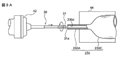
図3A〜図3Fを参照して、図2のステップS109のキャピラリの穴あけ加工の例を説明する。ここではホイールを用いる下穴加工とドリルを用いる仕上げ加工の2つの工程を含む例を説明する。仕上げ加工に用いるドリルは、穴あけ工具として市販されているものであってよい。一方、下穴加工に用いるホイールは、特別に製造された穴あけ工具を含む。先ず、図3A〜図3Cを参照して、ホイールを用いる下穴加工を説明する。図3Aに示すように、ホイール30は円筒状又は円柱状のリーマ部31を有する。リーマ部31は、平坦な先端面31aを有する。リーマ部31の構成の例は後に説明する。ホイール30の後端部は例えば旋盤のチャック42に固定される。一方、仮焼体230は適当な固定装置44によって固定される。固定装置44は例えば旋盤の固定部に装着される。仮焼体230は、図1Bに示した放電容器130と略同様な形状を有する。仮焼体230は、中央の発光部230Cと両側の細管部230A、230B(一方の細管部230Aのみ図示)を有する。細管部230Aには原孔230dが形成されている。
With reference to FIG. 3A to FIG. 3F, an example of capillary drilling in step S109 of FIG. 2 will be described. Here, an example including two steps of pilot hole machining using a wheel and finishing machining using a drill will be described. The drill used for finishing may be commercially available as a drilling tool. On the other hand, wheels used for drilling holes include specially manufactured drilling tools. First, with reference to FIGS. 3A to 3C, pilot hole machining using a wheel will be described. As shown in FIG. 3A, the
図3Bに示すように、ホイール30を回転させながら、原孔230dに挿入する。ホイール30の先端のリーマ部31は細管部230Aの原孔230dの内部に進入する。このとき、リーマ部31の先端部に冷却液46が供給される。冷却液46は、例えば、水であってよい。冷却液46は、細管部230Aの原孔230dを介してリーマ部31の先端部に供給され、リーマ部31を冷却する。
As shown in FIG. 3B, the
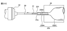
図3Cに示すように、下穴加工によって、細管部230Aの先端に、原孔230dの内径より大きい内径の下穴231が形成される。下穴231の内径及び深さ(軸線方向の寸法)は後に説明する。
As shown in FIG. 3C, a
次に、図3D〜図3Fを参照して、ドリルを用いた仕上げ加工を説明する。図3Dに示すように、ホイール30の代わりにドリル40を旋盤のチャック42に固定する。図3Eに示すように、ドリル40を回転させながら、細管部230Aの先端の下穴231に挿入する。ドリル40を前進させると、ドリル40の先端は、原孔230dの開口端に接触し、更に、原孔230dの内部に進入する。ドリル40の先端は、細管部230Aの下穴231によって案内されているから、振れることなく、仮焼体230の中心軸線に沿って進む。ドリル40が細管部230Aの原孔230dを貫通したら、図3Fに示すように、ドリル40を後退させ、ドリル40を細管部230Aから抜き出す。こうして、仮焼体230の細管部230Aに加工穴232が形成される。
Next, with reference to FIG. 3D to FIG. 3F, finishing using a drill will be described. As shown in FIG. 3D, a
以上、キャピラリの穴あけ加工の例として、ホイールを用いる下穴加工とドリルを用いる仕上げ加工の2つの工程を含む例を説明した。ホイールを用いる単一の穴あけ加工の例の場合には、図3Bの工程において、ホイール30による加工を、細管部230Aの原孔230dを貫通するまで、継続すればよい。
As described above, as an example of capillary drilling processing, an example including two steps of pilot hole processing using a wheel and finishing processing using a drill has been described. In the case of a single drilling process using a wheel, in the process of FIG. 3B, the process by the
図4Aを参照して、従来のキャピラリの穴あけ加工方法の欠点を説明する。従来のキャピラリの穴あけ加工方法では、ドリルのみを用い、本発明のようにホイール30を用いない。図4Aは、ドリル40の先端部と。仮焼体230の細管部230Aの先端部を拡大して描いた図であるが、説明の都合上、寸法及び形状は実際よりも誇張して描いている。ドリル40の中心軸線D−Dは仮焼体230の発光部230Cの中心軸線に整合しているものと仮定する。発光部230Cの中心軸線を、以下、単に仮焼体230の中心軸線O−Oと称する。
With reference to FIG. 4A, the disadvantage of the conventional capillary drilling method will be described. In the conventional capillary drilling method, only a drill is used, and the
図示の例では、細管部230Aの原孔230dの中心軸線B−Bは、仮焼体230の中心軸線O−Oに整合していない。仮焼体230の中心軸線O−Oに対する細管部230Aの原孔230dの中心軸線B−Bの偏芯量をδとする。細管部230Aには、直径方向両側に、肉薄部230AUと肉厚部230ADが生じている。この場合には、ドリル40の中心軸線D−Dは、仮焼体230の中心軸線O−Oに整合しているが、細管部230Aの原孔230dの中心軸線B−Bに整合していない。
In the illustrated example, the central axis BB of the
通常、ドリル40は円錐状の先端面40aを有する。一方、細管部230Aは、原孔230dの開口の周囲の環状の先端面230aを有する。従って、回転しているドリル40を細管部230Aの先端面230aに近づけると、ドリル40の先端面40aは、容易に、原孔230dの開口に係合する。ドリル40を更に原孔230dの内部に向けて移動させると、原孔230dの内部に進入する。原孔230dの中心軸線B−Bがドリルの中心軸線D−Dよりずれているため、細管部230A又はドリル40の先端部は撓む。その結果、原孔230dの中心軸線B−Bはドリルの中心軸線D−Dに整合することとなる。この状態で、原孔230dの内面が削られる。細管部230Aの原孔230dは、ドリル加工によって均等な厚さに削られ、原孔230dの中心軸線B−Bに整合した加工孔が形成される。即ち、細管部230Aには、仮焼体230の中心軸線O−Oに対して偏芯した加工孔が形成される。
Usually, the
図4Bを参照して、本発明の実施形態によるキャピラリの穴あけ加工方法の利点を説明する。図4Bは、図3Aに示したホイール30のリーマ部31と、仮焼体230の細管部230Aの先端部を拡大して描いた図であるが、説明の都合上、寸法及び形状は実際よりも誇張して描いている。同様に、図示の例では、細管部230Aの原孔230dの中心軸線B−Bは、仮焼体230の中心軸線O−Oに整合していない。仮焼体230の中心軸線O−Oに対する細管部230Aの原孔230dの中心軸線B−Bの偏芯量をδとする。細管部230Aには、下穴231が形成されている。ホイール30の中心軸線H−Hは、仮焼体230の中心軸線O−Oに整合しているが、細管部230Aの原孔230dの中心軸線B−Bに整合していない。
With reference to FIG. 4B, advantages of the capillary drilling method according to the embodiment of the present invention will be described. 4B is an enlarged view of the
図4Bに示すように、本実施形態では、ホイール30のリーマ部31の先端面31aは平坦面であり軸線方向に対して直交している。そのため、回転しているホイール30のリーマ部31を細管部230Aの先端面230aに近づけると、ホイール30の先端面31aの周縁部31bは、細管部230Aの環状の先端面230aに当接する。ホイール30を更に原孔230dの内部に向けて移動させると、ホイール30の先端面31aは、細管部230Aの環状の先端面230aを削りながら進む。従って細管部230Aは撓むことがなく、ホイール30の先端面31aは原孔230dの内部を進行する。即ち、原孔230dの中心軸線B−Bがホイール30の中心軸線H−Hに整合しない状態で、原孔230dの内面が削られる。細管部230Aの原孔230dは、ホイール加工によって不均等な厚さに削られ、原孔230dの中心軸線B−Bに整合しない下穴又は加工孔が形成される。即ち、細管部230Aには、仮焼体230の中心軸線O−Oに整合した下穴又は加工孔が形成される。
As shown in FIG. 4B, in this embodiment, the
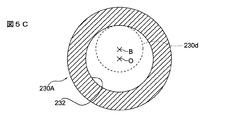
図5A、図5B、及び、図5Cを参照して説明する。図5Aは、穴あけ加工前の細管部230Aの断面構成を模式化して描いたものである。細管部230Aの原孔230dの中心軸線B−Bは、仮焼体230の中心軸線O−Oに整合していない。従って、細管部230Aには、直径方向両側に、肉薄部230AUと肉厚部230ADが生じている。図5Bは、従来のキャピラリの穴あけ加工方法によって、細管部230Aの原孔230dが加工された結果を示す。穴あけ加工によって、細管部230Aの原孔230dは均等な厚さに削り取られている。細管部230Aに形成された加工孔232の中心軸線は原孔230dの中心軸線B−Bに整合しているが、仮焼体230の中心軸線O−Oに整合していない。図5Cは、本実施形態によるキャピラリの穴あけ加工方法によって、細管部230Aの原孔230dが削り取られた結果を示す。穴あけ加工によって、細管部230Aの原孔230dは不均等な厚さに削り取られている。即ち、肉薄部230AUでは、削り取られる量は比較的少ないが、肉厚部230ADでは、削り取られる量は比較的多い。細管部230Aに形成された加工孔232の中心軸線は、原孔230dの中心軸線B−Bに整合していないが、仮焼体230の中心軸線O−Oに整合している。
This will be described with reference to FIGS. 5A, 5B, and 5C. FIG. 5A schematically illustrates a cross-sectional configuration of the
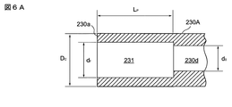
図6A、図6B及び図6Cを参照して仮焼体の細管部とホイールの先端部とドリルの先端部の寸法の例を説明する。図6Aに示すように、細管部230Aの外径をDc、原孔230aの内径をd0、下穴231の内径をdf、下穴231の軸線方向の寸法をLp、とする。尚、加工穴232(図3F)の内径は下穴231の内径dfに等しいものとする。図6Bに示すように、リーマ部31の先端面31aの外径をDRとする。図6Cに示すように、ドリル40の先端面40aの外径をDDとし、ドリル40の先端面40aの軸線方向の厚さをMaする。本願の発明者が行った実験では、これらの寸法は次のとおりである。
Dc=2.0mm
d0=1.5mm
df=DR=1.7mm
Lp=4.0mm
DD=1.8mm
Ma=DD/3.4=0.5mm
6A, 6B, and 6C, an example of the dimensions of the thin tube portion of the calcined body, the tip portion of the wheel, and the tip portion of the drill will be described. As shown in FIG. 6A, the outer diameter of the
Dc = 2.0mm
d 0 = 1.5 mm
df = D R = 1.7 mm
Lp = 4.0mm
D D = 1.8mm
Ma = D D /3.4=0.5 mm
上述のように本願の発明者が行った実験では、下穴231の軸線方向の寸法Lpは4.0mmであるが、本発明の実施の形態において下穴231の軸線方向の寸法Lpを検討する。上述のように仕上げ加工に用いるドリルは市販のものであってよいが、下穴加工に用いるホイールは特別に製造されたものを含む。一般に、ドリル40は安価であるが、ホイール30は高価である。工具の費用を低減化するには、ホイールの寿命を長く保つことが必要である。そのためには、下穴加工は出来るだけ少なく且つ短時間で完了させたい。即ち、経済的な観点からは下穴231の軸線方向の寸法Lpは短い方が良い。しかしながら、仕上げ加工において、良好な加工孔を得るには、下穴231の軸線方向の寸法Lpは、少なくともドリル40の進路を案内することができる長さが必要である。
In the experiment conducted by the inventor of the present application as described above, the dimension Lp in the axial direction of the
ここで、図6Cに示すように、ドリルの案内長さMbを定義する。ドリル40を下穴231に挿入したとき、ドリル40の先端面40aが原孔230dの開口に当接する。このとき、ドリルの外周面が下穴231の内周面に接触している部分を「案内長さ」と称することとする。下穴231の軸線方向の寸法Lpは少なくともドリルの案内長さMbより長い。上述のように本願の発明者が行った実験では、ドリルの案内長さMbは少なくとも2mmは必要であることが判った。以上より、本実施形態では、下穴231の軸線方向の寸法Lpは、少なくとも、下穴231の内径dfより大きく、好ましくは、下穴231の内径dfの2〜4倍とする。
Here, as shown in FIG. 6C, a guide length Mb of the drill is defined. When the
図7を参照して本願の発明者が行ったキャピラリの穴あけ加工の実験及びその結果を説明する。本願の発明者は、36本の仮焼体を用意し、18本の仮焼体を従来のキャピラリの穴あけ加工方法によって穴あけ加工し、残りの18本の仮焼体を本発明の実施形態によるキャピラリの穴あけ加工方法によって穴あけ加工した。図7は、本願の発明者が行った実験の結果を示すグラフである。このグラフの横軸は、穴あけ加工後に測定した細管部230Aに形成された加工孔232の中心軸線の芯ズレ量(単位:mm)であり、縦軸は、仮焼体の本数である。本発明のキャピラリの穴あけ加工方法を用いた場合、芯ズレ量はいずれも、0.08mm未満であった。一方、従来のキャピラリの穴あけ加工方法を用いた場合、芯ズレ量はいずれも、0.20mmを超えていた。
With reference to FIG. 7, an experiment and results of capillary drilling performed by the inventors of the present application will be described. The inventor of the present application prepares 36 calcined bodies, drills 18 calcined bodies by a conventional capillary drilling method, and the remaining 18 calcined bodies according to the embodiment of the present invention. Drilling was performed by a capillary drilling method. FIG. 7 is a graph showing the results of experiments conducted by the inventors of the present application. The horizontal axis of this graph is the amount of misalignment (unit: mm) of the center axis of the processed
図8A及び図8Bを参照して、本願の発明者が行った実験に使用したホイール30の形状の例を説明する。図8Aは、ホイール30の全体の外観を示す。ホイール30は本体32とリーマ部31を有する。図示の例では、リーマ部31の外径は本体32の外径より大きい。従って、本体32とリーマ部31の境界に段差ができている。しかしながら、これは単なる例示であって、本発明の実施形態では、リーマ部31の外径は本体32の外径と同一であってよい。
With reference to FIG. 8A and FIG. 8B, the example of the shape of the
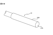
本実施形態によるとリーマ部31は加工用砥粒を電着させて形成した電着リーマと同様な構成であってよい。図8Bは、ホイール30のリーマ部31を示す。本実施形態によるとホイール30のリーマ部31は円柱状又は円筒状に形成され、平坦な先端面31aと円筒状の外周面31cを有する。
According to the present embodiment, the
先端面31aと外周面31cには、電着させた加工用砥粒が装着されている。尚、先端面31aと外周面31cに装着した加工用砥粒は単なる例であり、他の構造も可能である。例えば、先端面31aと外周面31cの表面に、微細なやすり面を形成してもよい。また、通常の形状のエンドミルを使用してもよい。超硬合金のチップを備えた工具であればさらに好ましい。
Electrodeposited abrasive grains are mounted on the
図9を参照して、本願の発明者が試作したホイールの形状の例を説明する。尚、図9では、ホイールの外径に対して軸線方向の寸法を意図的に小さく描いているため、ホイールの外径に対する軸線方向の寸法は実際のサンプルより小さいことに留意されたい。図示のように本願の発明者は、8種のホイール311〜318の例を試作し、穴あけ加工を行った。第1のホイール311は、単一の円柱形に形成され、先端面311aは、平坦な円形である。先端面311aの外径DRは、円柱形の外径に略等しい。先端面311aの周縁部311bは、僅かに面取り又は湾曲してもよい。
With reference to FIG. 9, the example of the shape of the wheel which the inventor of this application made as an experiment is demonstrated. In FIG. 9, it should be noted that since the dimension in the axial direction with respect to the outer diameter of the wheel is intentionally small, the dimension in the axial direction with respect to the outer diameter of the wheel is smaller than the actual sample. As shown in the drawing, the inventors of the present application made an example of eight types of
第2のホイール312は、円柱状の前部312Aと後部312Bからなる。先端面312aは、平坦な円形である。先端面の外径DRは、前部312Aの外径に等しい。前部312Aの外径は後部312Bの外径より小さい。第2のホイール312は、内径dfが比較的小さな下穴231を形成する場合、即ち、先端面312aの外径が比較的小さい場合に好適である。前部312Aによって下穴231が形成される。即ち、下穴の軸線方向の寸法Lp(図6A)は、前部312Aの軸線方向の寸法Laより小さくなる。従って、前部312Aの軸線方向の寸法Laが、予め設定された下穴231の軸線方向の寸法Lpより小さい場合には、ドリルを用いた仕上げ加工が困難となる。
The
第3のホイール313は、円柱状の前部312Aと後部312Bからなる。先端面312aは、平坦な円形である。先端面の外径DRは、前部312Aの外径に等しい。前部313Aの外径は後部313Bの外径より大きい。第3のホイール313は、内径dfが比較的大きな下穴231を形成する場合、即ち、先端面313aの外径が比較的大きい場合に好適である。
The
第4のホイール314は単一の円柱状に形成されているが、軸線方向の貫通孔314dを有する。従って、先端面314aは平坦な環状である。貫通孔を設けることによって加工くずを排出し易くなる。貫通孔314dの内径dRが原孔230dの内径d0より大きい場合には、削り残りが生じる可能性がある。従って、貫通孔314dの内径dRは少なくとも原孔230dの内径d0より小さいことが必要である。第4のホイール314は、内径dfが比較的大きな下穴231を形成する場合、即ち、先端面314aの外径が比較的大きい場合に好適である。
The
第5のホイール315は、回転円錐台状の前部315Aと円柱状の後部315Bからなる。先端面315aは、平坦な円形である。先端面315aの外径DRは、前部315Aの端面の外径に等しい。第5のホイール315の前部315Aの軸線方向の寸法をLcとする。第5のホイール315を用いた場合、細管部230Aに形成される下穴31の側面は、円筒状ではなく、円錐台状となる。
The
第6、第7及び第8のホイール316、317、318は、それぞれ、単一の円柱形に形成され、先端面316a、317a、318aは、それぞれ、凸部状円錐面、凸部状楕円面、及び、凹部状円錐面である。先端面の外径DRは、円柱形の外径に略等しい。
The sixth, seventh, and
本願の発明者は、これらのホイール311〜318を用いて穴あけ加工を行った。その結果、第1、第2、第3及び第4のホイール311、312、313及び314を用いた場合に、良好な加工孔が形成されることが判った。これらのホイールの場合、先端面311a、312a、313a、314aが仮焼体の細管部230Aの先端面230aに接触するとき、ホイールの先端面の外縁部(図4B)が接触するため、図4Bを参照して説明したように、ホイールの先端部が原孔230dに捕らわれることなく、前進する。
The inventor of the present application performed drilling using these
第5、第6、第7及び第8のホイール315〜318を用いた場合には、良好な結果が得られなかった。例えば、第5のホイール315を用いた場合、下穴231の内径dfが、リーマ部31の先端面31aの外径DRより大きくなる。第6のホイール316を用いた場合には、先端面316aが円錐形であるため、原孔230dに捕らわれる。従って、図4Aを参照して説明した従来の技術と同様に、ホイール316は原孔230dに案内されて、前進する。第7のホイール317を用いた場合も同様である。図8のホイール318を用いた場合には、下穴の底面に先端面318aの円錐形に対応した凸部が形成される。そのため、ドリルを用いた仕上げ加工の際に、ドリルの先端が下穴の底面の凸部に衝突し、その衝撃で細管部が割れる可能性ある。以上より、本発明の実施の形態では、第1〜第4のホイール311、312、313、314の形状が好ましい。
When the fifth, sixth, seventh and
以上、本実施形態に係るセラミックス製の放電容器の製造方法について説明したが、これらは例示であって、本発明の範囲を制限するものではない。当業者が、本実施形態に対して容易になしえる追加、削除、変更、改良等は、本発明の範囲内である。本発明の技術的範囲は、添付の特許請求の記載によって定められる。 As mentioned above, although the manufacturing method of the ceramic discharge container which concerns on this embodiment was demonstrated, these are illustrations and do not restrict | limit the scope of the present invention. Additions, deletions, modifications, improvements, and the like that can be easily made by those skilled in the art to the present embodiment are within the scope of the present invention. The technical scope of the present invention is defined by the appended claims.
30…ホイール、31…リーマ部、31a…先端面、31b…周縁部、31c…外周面、40…ドリル、40a…先端面、42…チャック、44…固定装置、46…冷却液、100…セラミックメタルハライドランプ、108…透光性スリーブ、109…フレーム、110…始動器、111…透光性外管、112…口金、113…ゲッタ、114…マウント支持板、115…ステム、120a、120b…電流導入体、121…リード線、122…電力供給導体、122a…耐ハロゲン性中間材、122b…導電性サーメット、123…タングステン電極、130…放電容器、130C…発光部、130A、130B…細管部、131…補強材、230…仮焼体、230A…細管部、230AU…肉薄部、230AD…肉厚部、230d…原孔、230a…先端面、230C…発光部、231…下穴、232…加工孔
DESCRIPTION OF
Claims (8)
アルミナ原料、助剤、及び、水を混合して生成したスラリーから成形体を形成する成形体形成ステップと、
前記成形体を仮焼して原孔を有する細管部を備えた仮焼体を形成する仮焼ステップと、
穴あけ工具であるホイールを用いて前記仮焼体の細管部の原孔に加工孔を形成する穴あけ加工ステップと、
前記キャピラリの穴あけ加工がされた仮焼体を本焼成する本焼成ステップと、
を有し、
前記ホイールは先端にリーマ部を備え、該リーマ部は、平坦な先端面と円筒状の外周面を有することを特徴とする放電容器の製造方法。 In the manufacturing method of the discharge vessel made of ceramics having the light emitting portion and the thin tube portions on both sides of the light emitting portion
A molded body forming step of forming a molded body from a slurry produced by mixing alumina raw material, auxiliary agent, and water,
Calcination step of calcining the molded body to form a calcined body having a narrow tube portion having original holes;
Drilling step of forming a processing hole in the original hole of the thin tube portion of the calcined body using a wheel that is a drilling tool;
A main firing step of subjecting the calcined body having been subjected to drilling of the capillary to main firing;
Have
The wheel includes a reamer at a tip, and the reamer has a flat tip and a cylindrical outer peripheral surface.
前記穴あけ加工ステップは、前記ホイールを用いて前記仮焼体の細管部の原孔に下穴を形成する下穴加工ステップと、前記下穴加工ステップ後にドリルを用いて前記仮焼体の細管部の原孔に加工孔を形成する仕上げ加工ステップを含むことを特徴とする放電容器の製造方法。 In the manufacturing method of the discharge vessel of Claim 1,
The drilling step includes a pilot hole processing step of forming a pilot hole in the original hole of the thin tube portion of the calcined body using the wheel, and a narrow tube portion of the calcined body using a drill after the pilot hole processing step. A method for manufacturing a discharge vessel, comprising a finishing step of forming a processing hole in the original hole.
前記穴あけ加工ステップにおいて、前記ホイールの中心軸線H−Hは前記仮焼体の中心軸線O−Oに整合して配置され、且つ、前記仮焼体の細管部の原孔の中心軸線B−Bが、前記仮焼体の中心軸線O−Oに整合していない場合に、前記仮焼体の細管部には、前記細管部の原孔の中心軸線B−Bに整合しないが、前記仮焼体の中心軸線O−Oに整合した加工孔が形成されることを特徴とする放電容器の製造方法。 In the manufacturing method of the discharge vessel of Claim 1,
In the drilling step, the center axis HH of the wheel is arranged in alignment with the center axis OO of the calcined body, and the center axis BB of the original hole of the thin tube portion of the calcined body However, when it is not aligned with the center axis OO of the calcined body, the narrow tube portion of the calcined body does not align with the center axis BB of the original hole of the narrow tube portion, but the calcined body A process for producing a discharge vessel, characterized in that a machining hole aligned with a central axis OO of a body is formed.
前記リーマ部は、円筒状の表面に加工用砥粒を電着して形成したものであることを特徴とする放電容器の製造方法。 In the manufacturing method of the discharge vessel of Claim 1,
The method of manufacturing a discharge vessel, wherein the reamer part is formed by electrodeposition of processing abrasive grains on a cylindrical surface.
前記ホイールは旋盤の回転部に装填されたチャックによって保持され、前記仮焼体は旋盤の固定部に装着された固定装置によって支持されていることを特徴とする放電容器の製造方法。 In the manufacturing method of the discharge vessel of any one of Claims 1-4,
The method of manufacturing a discharge vessel, wherein the wheel is held by a chuck loaded in a rotating part of a lathe, and the calcined body is supported by a fixing device attached to a fixing part of the lathe.
前記成形体形成ステップにおいて、前記成形体は排泥鋳込み法によって形成されることを特徴とする放電容器の製造方法。 In the manufacturing method of the discharge vessel of any one of Claims 1-5,
In the molded body forming step, the molded body is formed by a waste mud casting method.
前記ホイールの中心軸線H−Hは前記仮焼体の中心軸線O−Oに整合して配置され、且つ、前記仮焼体の細管部の原孔の中心軸線B−Bが、前記仮焼体の中心軸線O−Oに整合していない場合に、前記前記仮焼体の細管部には、前記細管部の原孔の中心軸線B−Bに整合しないが、前記仮焼体の中心軸線O−Oに整合した加工孔が形成されることを特徴とする放電容器の製造装置。 A fixing device for fixing a calcined body obtained by calcining a molded body formed from a slurry containing an alumina raw material, an auxiliary agent, and water, and a hole for forming a hole in the narrow tube portion of the calcined body In a discharge vessel manufacturing apparatus having a wheel, a chuck for fixing the wheel, and a rotating mechanism for rotating the chuck,
The center axis HH of the wheel is arranged in alignment with the center axis OO of the calcined body, and the center axis BB of the original hole of the thin tube portion of the calcined body is the calcined body. In the case where it is not aligned with the central axis OO of the calcined body, the thin tube portion of the calcined body does not align with the central axis BB of the original hole of the thin tube portion, but the central axis O of the calcined body is not aligned. An apparatus for manufacturing a discharge vessel, characterized in that a processing hole aligned with -O is formed.
前記ホイールは先端にリーマ部を備え、該リーマ部は、平坦な先端面と円筒状の外周面を有し、表面に加工用砥粒を電着して形成したものであることを特徴とする放電容器の製造装置。 In the discharge vessel manufacturing apparatus according to claim 7,
The wheel is provided with a reamer at the tip, the reamer having a flat tip surface and a cylindrical outer peripheral surface, and formed by electrodeposition of processing abrasive grains on the surface. Discharge vessel manufacturing equipment.
Priority Applications (1)
| Application Number | Priority Date | Filing Date | Title |
|---|---|---|---|
| JP2015238110A JP2017103191A (en) | 2015-12-05 | 2015-12-05 | Manufacturing method of ceramic discharge container |
Applications Claiming Priority (1)
| Application Number | Priority Date | Filing Date | Title |
|---|---|---|---|
| JP2015238110A JP2017103191A (en) | 2015-12-05 | 2015-12-05 | Manufacturing method of ceramic discharge container |
Publications (1)
| Publication Number | Publication Date |
|---|---|
| JP2017103191A true JP2017103191A (en) | 2017-06-08 |
Family
ID=59017559
Family Applications (1)
| Application Number | Title | Priority Date | Filing Date |
|---|---|---|---|
| JP2015238110A Pending JP2017103191A (en) | 2015-12-05 | 2015-12-05 | Manufacturing method of ceramic discharge container |
Country Status (1)
| Country | Link |
|---|---|
| JP (1) | JP2017103191A (en) |
-
2015
- 2015-12-05 JP JP2015238110A patent/JP2017103191A/en active Pending
Similar Documents
| Publication | Publication Date | Title |
|---|---|---|
| CN104912488B (en) | Diamond core boring bit head of rod and preparation method thereof is drawn for sapphire | |
| US6211615B1 (en) | Powder metal electrode component for discharge lamps | |
| KR100670688B1 (en) | Short Arc Type High Pressure Discharge Lamp | |
| KR20110105732A (en) | Elevated Conical Graphite Electrodes | |
| JPH11135011A (en) | Electrode for high-voltage discharge lamp, its manufacture, manufacture device, and high-voltage discharge lamp | |
| CN116140625B (en) | Preparation method of wedge-shaped riving knife material | |
| US6346495B1 (en) | Die pressing arctube bodies | |
| WO2012029666A1 (en) | Hole boring drill for glass | |
| JP2017103191A (en) | Manufacturing method of ceramic discharge container | |
| JP2007254273A (en) | Alumina sintered body, processing apparatus member, processing apparatus and processing method using the same | |
| US8018156B2 (en) | High-pressure discharge lamp having a ceramic discharge vessel | |
| JP6526588B2 (en) | Method of manufacturing pellicle frame and pellicle frame | |
| JPH1064481A (en) | Ceramic tube for discharge lamp and method of manufacturing the same | |
| EP1708247A1 (en) | Luminous vessel comprising sintered body fixed to feedthrough | |
| US6819047B2 (en) | High pressure discharge lamps, and assemblies and discharge vessels therefor | |
| US20060222878A1 (en) | Composite bodies | |
| CN207414433U (en) | The indexable U-shaped drill bit of knife rest pinhole type of numerically controlled lathe | |
| KR101059638B1 (en) | Method for manufacturing excimer discharge lamp and excimer discharge lamp | |
| GB2275054A (en) | Tungsten articles and method for making them | |
| JP2011054428A (en) | Short arc discharge lamp | |
| GB2071904A (en) | Process for the production of waveguide lasers | |
| JP4832931B2 (en) | Method for producing sintered electrode for cold cathode tube | |
| CN209598998U (en) | A cemented carbide matrix brazed diamond grinding rod | |
| JP6116200B2 (en) | Manufacturing method of discharge lamp electrode | |
| SU1009783A1 (en) | Diamond drill |