JP2017104792A - Wastewater treatment equipment - Google Patents
Wastewater treatment equipment Download PDFInfo
- Publication number
- JP2017104792A JP2017104792A JP2015239541A JP2015239541A JP2017104792A JP 2017104792 A JP2017104792 A JP 2017104792A JP 2015239541 A JP2015239541 A JP 2015239541A JP 2015239541 A JP2015239541 A JP 2015239541A JP 2017104792 A JP2017104792 A JP 2017104792A
- Authority
- JP
- Japan
- Prior art keywords
- waste water
- wastewater
- electrodes
- treatment apparatus
- plasma
- Prior art date
- Legal status (The legal status is an assumption and is not a legal conclusion. Google has not performed a legal analysis and makes no representation as to the accuracy of the status listed.)
- Pending
Links
- 238000004065 wastewater treatment Methods 0.000 title claims abstract description 44
- 239000002351 wastewater Substances 0.000 claims abstract description 51
- 238000012545 processing Methods 0.000 claims abstract description 25
- 150000002894 organic compounds Chemical class 0.000 claims abstract description 24
- 150000004812 organic fluorine compounds Chemical class 0.000 claims abstract description 16
- 230000001699 photocatalysis Effects 0.000 claims abstract description 14
- 239000000126 substance Substances 0.000 claims abstract description 13
- 238000013032 photocatalytic reaction Methods 0.000 claims abstract description 10
- YFSUTJLHUFNCNZ-UHFFFAOYSA-N perfluorooctane-1-sulfonic acid Chemical compound OS(=O)(=O)C(F)(F)C(F)(F)C(F)(F)C(F)(F)C(F)(F)C(F)(F)C(F)(F)C(F)(F)F YFSUTJLHUFNCNZ-UHFFFAOYSA-N 0.000 claims description 21
- 239000000919 ceramic Substances 0.000 claims description 16
- 238000011282 treatment Methods 0.000 claims description 16
- 239000011148 porous material Substances 0.000 claims description 2
- 238000002474 experimental method Methods 0.000 description 33
- GWEVSGVZZGPLCZ-UHFFFAOYSA-N Titan oxide Chemical compound O=[Ti]=O GWEVSGVZZGPLCZ-UHFFFAOYSA-N 0.000 description 12
- XLYOFNOQVPJJNP-UHFFFAOYSA-N water Substances O XLYOFNOQVPJJNP-UHFFFAOYSA-N 0.000 description 8
- 230000000052 comparative effect Effects 0.000 description 6
- 239000000463 material Substances 0.000 description 6
- 239000004408 titanium dioxide Substances 0.000 description 6
- 238000006243 chemical reaction Methods 0.000 description 4
- 238000000354 decomposition reaction Methods 0.000 description 4
- 238000006864 oxidative decomposition reaction Methods 0.000 description 4
- 238000001816 cooling Methods 0.000 description 3
- SNGREZUHAYWORS-UHFFFAOYSA-N perfluorooctanoic acid Chemical compound OC(=O)C(F)(F)C(F)(F)C(F)(F)C(F)(F)C(F)(F)C(F)(F)C(F)(F)F SNGREZUHAYWORS-UHFFFAOYSA-N 0.000 description 3
- OKTJSMMVPCPJKN-UHFFFAOYSA-N Carbon Chemical compound [C] OKTJSMMVPCPJKN-UHFFFAOYSA-N 0.000 description 2
- JOYRKODLDBILNP-UHFFFAOYSA-N Ethyl urethane Chemical compound CCOC(N)=O JOYRKODLDBILNP-UHFFFAOYSA-N 0.000 description 2
- 239000006260 foam Substances 0.000 description 2
- 239000007788 liquid Substances 0.000 description 2
- 239000002245 particle Substances 0.000 description 2
- WFKWXMTUELFFGS-UHFFFAOYSA-N tungsten Chemical compound [W] WFKWXMTUELFFGS-UHFFFAOYSA-N 0.000 description 2
- 239000010937 tungsten Substances 0.000 description 2
- 229910052721 tungsten Inorganic materials 0.000 description 2
- 238000003466 welding Methods 0.000 description 2
- MYMOFIZGZYHOMD-UHFFFAOYSA-N Dioxygen Chemical compound O=O MYMOFIZGZYHOMD-UHFFFAOYSA-N 0.000 description 1
- CBENFWSGALASAD-UHFFFAOYSA-N Ozone Chemical compound [O-][O+]=O CBENFWSGALASAD-UHFFFAOYSA-N 0.000 description 1
- -1 PFOS Chemical class 0.000 description 1
- 238000006065 biodegradation reaction Methods 0.000 description 1
- 239000003795 chemical substances by application Substances 0.000 description 1
- 150000001875 compounds Chemical class 0.000 description 1
- 238000007796 conventional method Methods 0.000 description 1
- 238000013461 design Methods 0.000 description 1
- 238000010586 diagram Methods 0.000 description 1
- 229910001882 dioxygen Inorganic materials 0.000 description 1
- 239000006185 dispersion Substances 0.000 description 1
- 238000005516 engineering process Methods 0.000 description 1
- 230000002708 enhancing effect Effects 0.000 description 1
- 239000011521 glass Substances 0.000 description 1
- 230000001678 irradiating effect Effects 0.000 description 1
- 239000012528 membrane Substances 0.000 description 1
- 230000001590 oxidative effect Effects 0.000 description 1
- 239000004033 plastic Substances 0.000 description 1
- 229920001228 polyisocyanate Polymers 0.000 description 1
- 239000005056 polyisocyanate Substances 0.000 description 1
- 229920005862 polyol Polymers 0.000 description 1
- 150000003077 polyols Chemical class 0.000 description 1
- 238000004445 quantitative analysis Methods 0.000 description 1
- 238000000926 separation method Methods 0.000 description 1
- 239000002002 slurry Substances 0.000 description 1
- 239000007787 solid Substances 0.000 description 1
- 239000004094 surface-active agent Substances 0.000 description 1
- 238000005979 thermal decomposition reaction Methods 0.000 description 1
- 229910021642 ultra pure water Inorganic materials 0.000 description 1
- 239000012498 ultrapure water Substances 0.000 description 1
Images
Landscapes
- Water Treatment By Electricity Or Magnetism (AREA)
- Physical Water Treatments (AREA)
- Treatment Of Water By Oxidation Or Reduction (AREA)
Abstract
【課題】簡素な構成でありながら、排水中の有機化合物、特に水溶性有機フッ素化合物を高速で分解処理できる排水処理装置を提供する。
【解決手段】この排水処理装置1は、排水S中の有機化合物を分解処理するものであって、排水Sが流入する排水流入口2aと処理された排水Sが流出する排水流出口2a’を有する処理容器2と、処理容器2の内部で先端が互いに向き合うよう処理容器2の側面に取り付けられる2個の電極3A、3Bと、2個の電極3A、3Bに高周波数の高電圧パルスを印加し2個の電極3A、3Bの先端の間にプラズマを発生させる高電圧パルス印加器4と、処理容器2の内部であって2個の電極3A、3Bの排水流入口2a側及び排水流出口2a’側の両方に配置され、前記プラズマからの光により光触媒反応を起こす光触媒物質を担持する多孔質体5、5’と、を備えてなる。
【選択図】図1Disclosed is a wastewater treatment apparatus that can decompose organic compounds in wastewater, particularly water-soluble organic fluorine compounds, at high speed while having a simple configuration.
The waste water treatment apparatus 1 decomposes an organic compound in the waste water S. The waste water inlet 2a into which the waste water S flows and a drain outlet 2a 'from which the treated waste water S flows out. A high-frequency high-voltage pulse is applied to the processing container 2 that has the two electrodes 3A and 3B attached to the side surface of the processing container 2 so that the tips face each other inside the processing container 2 and the two electrodes 3A and 3B A high voltage pulse applicator 4 for generating plasma between the tips of the two electrodes 3A and 3B, and the drainage inlet 2a side and drainage outlet of the two electrodes 3A and 3B inside the processing vessel 2. 2a ′, and porous bodies 5 and 5 ′ that carry a photocatalytic substance that undergoes a photocatalytic reaction by light from the plasma.
[Selection] Figure 1
Description
本発明は、有機化合物を含有する排水を処理する排水処理装置、特にPFOSなどの水溶性有機フッ素化合物を含有する排水の処理に好適な排水処理装置に関する。 The present invention relates to a wastewater treatment apparatus for treating wastewater containing an organic compound, and particularly to a wastewater treatment apparatus suitable for treatment of wastewater containing a water-soluble organic fluorine compound such as PFOS.
パーフルオロオクタンスルホン酸(PFOS)などの水溶性有機フッ素化合物は、界面活性剤など様々な用途に用いられてきたが、これを含有する排水を処理する場合、化学的安定性が高いため分解処理が難しく、生物分解は言うまでもなく、種々の生物難分解性の処理に適用されているオゾン処理でも分解が難しい。そのため、従来の水溶性有機フッ素化合物の除去方法としては、一般に、活性炭処理や膜処理による分離での一定の除去が図られていた。 Water-soluble organic fluorine compounds such as perfluorooctane sulfonic acid (PFOS) have been used for various applications such as surfactants. However, when wastewater containing this is treated, it is decomposed due to its high chemical stability. However, it is difficult to decompose even by ozone treatment applied to various biodegradable treatments, not to mention biodegradation. Therefore, as a conventional method for removing a water-soluble organic fluorine compound, in general, a certain removal by separation by activated carbon treatment or membrane treatment has been attempted.
近年、プラズマによる水溶性有機フッ素化合物の分解処理が報告されている。例えば、特許文献1には、液体中に気泡を供給しその気泡内にプラズマを発生させて、水溶性有機フッ素化合物の一つであるパーフルオロオクタン酸(PFOA)を分解処理する排水処理装置が開示されている。
In recent years, decomposition treatment of water-soluble organic fluorine compounds by plasma has been reported. For example,
しかしながら、特許文献1に開示されている排水処理装置にあっては、水溶性有機フッ素化合物を高速で分解処理するためには、酸素ガスの気泡を連続して供給する必要があり、そのために、排水処理装置が大規模なものとなる。
However, in the wastewater treatment apparatus disclosed in
本発明は係る事由に鑑みてなされたものであり、その目的は、簡素な構成でありながら、排水中の有機化合物、特に水溶性有機フッ素化合物を高速で分解処理できる排水処理装置を提供することにある。 SUMMARY OF THE INVENTION The present invention has been made in view of the above reasons, and an object thereof is to provide a wastewater treatment apparatus that can decompose organic compounds in wastewater, particularly water-soluble organic fluorine compounds, at high speed while having a simple configuration. It is in.
上記目的を達成するために、請求項1に記載の排水処理装置は、排水中の有機化合物を分解処理する排水処理装置であって、前記排水が流入する排水流入口と前記排水中の前記有機化合物を分解処理した後の前記排水が流出する排水流出口を有する処理容器と、該処理容器の内部で先端が互いに向き合うよう該処理容器の側面に取り付けられる2個の電極と、該2個の電極の間に高周波数の高電圧パルスを印加し該2個の電極の前記先端の間にプラズマを発生させる高電圧パルス印加器と、前記処理容器の内部であって前記2個の電極の前記排水流入口側及び前記排水流出口側の両方又は一方に配置され、前記プラズマからの光により光触媒反応を起こす光触媒物質を担持する多孔質体と、を備えてなることを特徴とする。
In order to achieve the above object, the wastewater treatment apparatus according to
請求項2に記載の排水処理装置は、請求項1に記載の排水処理装置において、前記有機化合物は、水溶性有機フッ素化合物であることを特徴とする。
The waste water treatment apparatus according to
請求項3に記載の排水処理装置は、請求項2に記載の排水処理装置において、前記水溶性有機フッ素化合物は、PFOSであることを特徴とする。
The waste water treatment apparatus according to claim 3 is the waste water treatment apparatus according to
請求項4に記載の排水処理装置は、請求項1〜3のいずれか1項に記載の排水処理装置において、前記多孔質体は、セラミックスの多孔質体であることを特徴とする。
The waste water treatment apparatus according to claim 4 is the waste water treatment apparatus according to any one of
本発明の排水処理装置によれば、簡素な構成でありながら、排水中の有機化合物、特に水溶性有機フッ素化合物を高速で分解処理できる。 According to the waste water treatment apparatus of the present invention, an organic compound, particularly a water-soluble organic fluorine compound in waste water can be decomposed at high speed with a simple configuration.
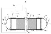
以下、本発明を実施するための形態を説明する。本発明の実施形態に係る排水処理装置1は、有機化合物、特に難分解性の有機化合物として広く知られているPFOSなどの水溶性有機フッ素化合物を含有する排水Sの処理が可能なものである。この排水処理装置1は、図1に示すように、処理容器2と、2個の電極3A、3Bと、高電圧パルス印加器4と、多孔質体5、5’と、を備えてなる。
Hereinafter, modes for carrying out the present invention will be described. The
処理容器2は、排水Sが流入する排水流入口2aと、排水S中の有機化合物を分解処理した後の排水Sが流出する排水流出口2a’を有する。処理容器2は、円筒状の処理容器本体21と、処理容器本体21の一方側に取り付けられ排水流入口2aが設けられるキャップ体22と、処理容器本体21の他方側に取り付けられ排水流出口2a’が設けられるキャップ体22’と、で構成したものとすることができる。処理容器本体21は、例えば、耐熱ガラス製、キャップ体22とキャップ体22’は、例えば、プラスチック製とすることができる。また、排水流入口2aにはチューブ6Aを接続してそれから排水Sを流入させ、排水流出口2a’にはチューブ6A’を接続してそれに排水Sを流出させることができる。なお、図1において符号23、23’で示すものは、処理容器本体21にキャップ体22、22’を固定する固定用部材である。
The
処理容器2は、処理容器本体21の一方側端部近傍に、大きな固形物が流入しないようにそれを阻止するフィルター6Bを配置し、他方側端部近傍に、多孔質体5、5’などが万一削れたりしたときにそれが流出しないように阻止するフィルター6B’を配置することができる。
In the
2個の電極3A、3Bは、処理容器2(より詳細には、処理容器本体21)の内部で先端が互いに向き合うよう処理容器2の側面に取り付けられる。2個の電極3A、3Bは、細い線材であり、例えば、タングステン製である。詳細には、2個の電極3A、3Bはそれぞれ、電極固定材6CA、6CBに形成された貫通孔に挿通した状態でそれに固定され、電極固定材6CA、6CBは、互いに向き合うよう処理容器2の側面に取り付けられる。2個の電極3A、3Bの先端は、その間にプラズマが発生可能なように所定の距離だけ離れている。
The two electrodes 3 </ b> A and 3 </ b> B are attached to the side surface of the
高電圧パルス印加器4は、2個の電極3A、3Bの間に高周波数の高電圧パルスを印加し2個の電極3A、3Bの先端の間にプラズマを発生させるものである。高電圧パルスは、例えば、周波数が20kHz〜30kHz、電圧が200V〜250Vのパルスである。
The high voltage pulse applicator 4 generates a plasma between the tips of the two
多孔質体5、5’は、処理容器2の内部であって2個の電極3A、3Bの一方側、すなわち排水流入口2a側、及び他方側、すなわち排水流出口2a’側に配置される。多孔質体5、5’は、2個の電極3A、3Bの先端の間に発生するプラズマからの光により光触媒反応を起こす光触媒物質を担持している。光触媒反応は、光(特に、紫外線)を光触媒物質に照射することによって、その表面において発生する強い酸化力を有する正孔を利用する反応である。また、多孔質体5、5’は、通常、セラミックスの多孔質体である。光触媒物質は、二酸化チタンとすることができる。
The
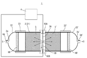
このような構成の排水処理装置1は、2個の電極3A、3Bの間に高周波数の高電圧パルスが高電圧パルス印加器4により印加されると、2個の電極3A、3Bの先端の間に電流が流れ、ジュール熱により2個の電極3A、3Bの先端の間は局所的に高温になる。そうすると、2個の電極3A、3Bの先端の間に気泡が発生し、その気泡内に、図2に示すように、プラズマ(図2において符号Pで示す。)が発生する。排水Sに含有される有機化合物は、プラズマによって起こる反応で分解される。プラズマによって起こる分解反応は、プラズマ粒子による酸化分解反応、プラズマ発生に伴う温度上昇による熱分解反応、プラズマ粒子と排水Sとの接触により生成されるOHラジカルなどの各種ラジカルによる酸化分解反応、である。
In the
2個の電極3A、3Bの先端の間に発生するプラズマは、紫外線を含む強い光(図2において中央の放射状の矢印付き実線で示す。)を発する。この光は、多孔質体5、5’に照射される。多孔質体5、5’は、その多数の空孔に光触媒物質を担持しており、光触媒物質は、2個の電極3A、3Bの先端の間に近接する部分から光の到達する部分までの広い範囲で、光触媒反応で排水Sに含有される有機化合物を分解する。この光触媒反応は、正孔による酸化分解反応、正孔と排水Sとの接触により生成されるOHラジカルなどの各種ラジカルによる酸化分解反応、である。
The plasma generated between the tips of the two
このように排水処理装置1は、有機化合物を、プラズマによって起こる反応で分解するとともに、プラズマから発せられる強い光を利用して広い範囲で光触媒反応で分解することができる。そうすることで、排水処理装置1は、排水S中の有機化合物を高速に分解処理することができ、しかも、簡素な構成とすることができる。
As described above, the
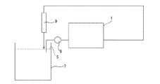
次に、本願発明者が行った実験(実験1〜3)について以下説明する。実験装置としては、図3に示すように、排水処理装置1、排水Sを貯留する水槽7、この水槽7から排水処理装置1に排水Sを送り込むポンプ8、排水処理装置1から水槽7に排水Sを戻すときに排水Sの温度を水槽7の温度に戻す冷却管9、を備えた構成である。排水処理装置1の中の2個の電極3A、3Bは、パナソニック溶接システム株式会社製の直径1.0mmの溶接用タングステン電極YN10L2Sを用いた。高電圧パルス印加器4は、株式会社栗田製作所製のパルス電源装置MPS−06K0を用い、パルストランスを介して出力するようにした。
Next, experiments (
多孔質体5、5’はそれぞれ、光触媒物質を担持する円柱状の2個のセラミックスの多孔質体を重ね合わせたものを用いた。つまり、合計4個のセラミックスの多孔質体を用いた。各々のセラミックスの多孔質体は、直径25mm、長さ15mmのものである。光触媒物質は、二酸化チタンを用いた。各々のセラミックスの多孔質体は、以下のようにして作製されたものである。すなわち、ポリオールとポリイソシアネートから発泡ウレタンフォームを合成する。その発泡ウレタンフォームに対しセラミック剤を塗布し、これを約1200℃にて焼成してセラミックの多孔質体を作製する。そのセラミックの多孔質体を二酸化チタン分散スラリーに浸漬すると共に、余剰付着分をエアーブラシで取り除く。そして、約60℃で乾燥し、その後、約500℃にて焼成し、その後、冷却する。
As the
分解処理すべき有機化合物はPFOSとした。PFOSの濃度が100mg/Lの排水Sを300mL作製して水槽7に注入した。処理に要する時間は240分間とし、ポンプ8による排水Sの流速を76mL/minとし、排水Sを水槽7、ポンプ8、排水処理装置1、冷却管9を通して循環させた。実験時間中20分毎に水槽7の排水Sから100μLをマイクロピペットを用いて採取した。採取した排水Sを超純水で100倍希釈し、液体クロマトグラフ質量分析装置(アジレント・テクノロジー株式会社製1100シリーズLC/MS)による定量分析を行った。
The organic compound to be decomposed was PFOS. 300 mL of waste water S having a PFOS concentration of 100 mg / L was prepared and injected into the water tank 7. The time required for the treatment was 240 minutes, the flow rate of the waste water S by the pump 8 was 76 mL / min, and the waste water S was circulated through the water tank 7, the pump 8, the waste
実験1では、2個の電極3A、3Bの間に、電圧250V、周波数20.0kHz、パルス幅3.00μSの高周波数の高電圧パルスを印加した。実験1では、1個のセラミックスの多孔質体について二酸化チタンを2.24mg担持させた。また、実験1との比較のために、比較実験1〜3を行った。比較実験1は、実験1に対して、2個の電極3A、3Bの間に高周波数の高電圧パルスを印加せず(プラズマを発生させず)、光触媒物質を担持しないセラミックスの多孔質体を用いた実験である。比較実験2は、実験1に対して、2個の電極3A、3Bの間に高周波数の高電圧パルスを印加し(プラズマを発生させ)、セラミックスの多孔質体を用いない実験である。比較実験3は、実験1に対して、2個の電極3A、3Bの間に高周波数の高電圧パルスを印加し(プラズマを発生させ)、光触媒物質を担持しないセラミックスの多孔質体を用いた実験である。
In
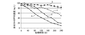
図4に、実験1の結果を曲線a、比較実験1の結果を曲線b、比較実験2の結果を曲線c、比較実験3の結果を曲線d、で示す。横軸は処理時間(分)、縦軸は排水S中のPFOSの濃度(mg/L)である。同図から、実験終了時(実験開始から240分後)における排水S中のPFOSの濃度が最も低い値を示したのは、曲線aの場合であり、実験を通じ排水S中のPFOSの約89.7%の除去が認められた。これに対し、曲線bの場合における排水S中のPFOSの除去率は約9.9%、曲線cの場合における排水S中のPFOSの除去率は約45%、曲線dの場合における排水S中のPFOSの除去率は約79.3%、であった。また、曲線aは曲線dに比べて、処理時間の早いうちからPFOSの除去が進んでいることが認められた。このように得られた実験結果から、有機化合物を、プラズマによって起こる反応で分解するとともに、プラズマから発せられる強い光を利用して多孔質体5、5’の中における広い範囲で光触媒反応で分解すると、排水S中の有機化合物を高速に分解して除去できることが分かる。
FIG. 4 shows the result of
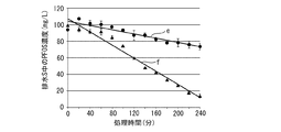
実験2及び実験3では、2個の電極3A、3Bの間に、電圧200V、周波数30.0kHz、パルス幅5.50μSの高周波数の高電圧パルスを印加した。実験2及び実験3は、実験1とは2個の電極3A、3Bの間に印加される高周波数の高電圧パルスを異ならせてプラズマのエネルギーを小さくしており、実験1よりも高電圧パルス印加器4にかかる負荷を小さくしている。そして、実験2では、1個のセラミックスの多孔質体について二酸化チタンを2.24mg担持させたものを用い、実験3では、1個のセラミックスの多孔質体について二酸化チタンを4.50mg担持させたものを用いた。
In
図5に、実験2の結果を曲線e、実験3の結果を曲線f、で示す。横軸は処理時間(分)、縦軸は排水S中のPFOSの濃度(mg/L)である。同図から、実験終了時(実験開始から240分後)における排水S中のPFOSの濃度は、曲線eでは約73.7mg/Lであったことに対し、曲線fでは約13.9mg/Lまで低減している。これらの結果をPFOSの除去率で換算すると、曲線eでは排水S中のPFOSの除去率は約21.2%であり、曲線fでは排水S中のPFOSの除去率は約86.0%となった。曲線eと曲線fの比較においては、光触媒物質の担持量を増やすことにより、排水S中の有機化合物の分解除去を促進できることが分かる。また、曲線fと上述した曲線aとの比較においては、プラズマのエネルギーを小さくしても、光触媒反応を増強することで、排水S中の有機化合物を高速に分解して除去できることが分かる。
FIG. 5 shows the result of
以上、本発明の実施形態に係る排水処理装置について説明したが、本発明は、上述の実施形態に記載したものに限られることなく、特許請求の範囲に記載した事項の範囲内でのさまざまな設計変更が可能である。例えば、多孔質体5、5’のうちどちらかを省略することも、場合によっては可能である。また、本発明の実施形態に係る排水処理装置は、PFOSに限らず、PFOAなどの他の水溶性有機フッ素化合物を含有する排水を処理することが可能であり、更には、水溶性有機フッ素化合物に限らず、その他の有機化合物を含有する排水を処理することが可能である。
As mentioned above, although the waste water treatment equipment concerning the embodiment of the present invention was explained, the present invention is not restricted to what was described in the above-mentioned embodiment, but various in the range of the matter described in the claim. Design changes are possible. For example, it is possible to omit one of the
1 排水処理装置
2 処理容器
2a 処理容器の排水流入口
2a’ 処理容器の排水流出口
21 処理容器本体
22、22’ キャップ体
23、23’ 固定用部材
3A、3B 電極
4 高電圧パルス印加器
5、5’ 多孔質体
6A、6A’ チューブ
6B、6B’ フィルター
6CA、6CB 電極固定材
7 水槽
8 ポンプ
9 冷却管
S 排水
DESCRIPTION OF
Claims (4)
前記排水が流入する排水流入口と前記排水中の前記有機化合物を分解処理した後の前記排水が流出する排水流出口を有する処理容器と、
該処理容器の内部で先端が互いに向き合うよう該処理容器の側面に取り付けられる2個の電極と、
該2個の電極の間に高周波数の高電圧パルスを印加し該2個の電極の前記先端の間にプラズマを発生させる高電圧パルス印加器と、
前記処理容器の内部であって前記2個の電極の前記排水流入口側及び前記排水流出口側の両方又は一方に配置され、前記プラズマからの光により光触媒反応を起こす光触媒物質を担持する多孔質体と、
を備えてなることを特徴とする排水処理装置。 A wastewater treatment apparatus for decomposing organic compounds in wastewater,
A wastewater inlet into which the wastewater flows and a treatment container having a wastewater outlet from which the wastewater flows out after decomposing the organic compound in the wastewater;
Two electrodes attached to the side surface of the processing container such that the tips thereof face each other inside the processing container;
A high voltage pulse applicator for applying a high frequency high voltage pulse between the two electrodes to generate a plasma between the tips of the two electrodes;
A porous material that is disposed in the processing vessel and on either or both of the drainage inlet side and the drainage outlet side of the two electrodes, and carries a photocatalytic substance that causes a photocatalytic reaction by light from the plasma. Body,
A wastewater treatment apparatus comprising:
前記有機化合物は、水溶性有機フッ素化合物であることを特徴とする排水処理装置。 The waste water treatment apparatus according to claim 1,
The waste water treatment apparatus, wherein the organic compound is a water-soluble organic fluorine compound.
前記水溶性有機フッ素化合物は、PFOSであることを特徴とする排水処理装置。 The waste water treatment apparatus according to claim 2,
The waste water treatment apparatus, wherein the water-soluble organic fluorine compound is PFOS.
前記多孔質体は、セラミックスの多孔質体であることを特徴とする排水処理装置。 In the waste water treatment equipment according to any one of claims 1 to 3,
The waste water treatment apparatus, wherein the porous body is a ceramic porous body.
Priority Applications (1)
| Application Number | Priority Date | Filing Date | Title |
|---|---|---|---|
| JP2015239541A JP2017104792A (en) | 2015-12-08 | 2015-12-08 | Wastewater treatment equipment |
Applications Claiming Priority (1)
| Application Number | Priority Date | Filing Date | Title |
|---|---|---|---|
| JP2015239541A JP2017104792A (en) | 2015-12-08 | 2015-12-08 | Wastewater treatment equipment |
Publications (1)
| Publication Number | Publication Date |
|---|---|
| JP2017104792A true JP2017104792A (en) | 2017-06-15 |
Family
ID=59058919
Family Applications (1)
| Application Number | Title | Priority Date | Filing Date |
|---|---|---|---|
| JP2015239541A Pending JP2017104792A (en) | 2015-12-08 | 2015-12-08 | Wastewater treatment equipment |
Country Status (1)
| Country | Link |
|---|---|
| JP (1) | JP2017104792A (en) |
Cited By (1)
| Publication number | Priority date | Publication date | Assignee | Title |
|---|---|---|---|---|
| US12410071B1 (en) | 2020-10-19 | 2025-09-09 | Wm Intellectual Property Holdings, L.L.C. | System and method for removal of PFAS and other emerging contaminant micro-constituents from landfill leachate and other impacted liquids |
-
2015
- 2015-12-08 JP JP2015239541A patent/JP2017104792A/en active Pending
Cited By (1)
| Publication number | Priority date | Publication date | Assignee | Title |
|---|---|---|---|---|
| US12410071B1 (en) | 2020-10-19 | 2025-09-09 | Wm Intellectual Property Holdings, L.L.C. | System and method for removal of PFAS and other emerging contaminant micro-constituents from landfill leachate and other impacted liquids |
Similar Documents
| Publication | Publication Date | Title |
|---|---|---|
| JP5067802B2 (en) | Plasma generating apparatus, radical generating method, and cleaning and purifying apparatus | |
| US10519051B2 (en) | Systems and methods for the treatment of ballast water | |
| JP5142984B2 (en) | Apparatus and method for the purification and sterilization of liquid, solid or gaseous substances | |
| JP4041224B2 (en) | Liquid processing method and liquid processing apparatus | |
| KR20140108667A (en) | Process for treating effluents in a bed of microbeads by cold plasma and photocatalysis | |
| US20030146310A1 (en) | Method, process and apparatus for high pressure plasma catalytic treatment of dense fluids | |
| JP2004268003A (en) | Underwater discharge plasma method and liquid treatment apparatus | |
| KR20110109111A (en) | Water treatment device and method using plasma gun | |
| US9409800B2 (en) | Electric arc for aqueous fluid treatment | |
| KR101497591B1 (en) | Apparatus for treating water using discharge in reactor | |
| JP2010137212A (en) | Apparatus for generating plasma | |
| Wang et al. | Degradation of pharmaceutical contaminants in wastewater by non-thermal plasma technology: A comprehensive Review | |
| JP2025181832A (en) | Plasma Water Treatment | |
| JP2017104792A (en) | Wastewater treatment equipment | |
| KR101843661B1 (en) | Hybrid apparatus and method for water treatment using plasma | |
| US10280098B2 (en) | Submerged arc removal of contaminants from liquids | |
| Attri et al. | Plasma technology: a new remediation for water purification with or without nanoparticles | |
| KR101418385B1 (en) | Purification processing system of waste-water using high voltage dischare and minuteness bubble | |
| Liu et al. | Degradation of basic and acid dyes in high-voltage pulsed discharge | |
| RU2326820C1 (en) | Method of cleaning and sterilisation of liquid or gas media and device for method implemention | |
| JP2012176347A (en) | Method and device for generating active species | |
| KR101759617B1 (en) | Ozone generator using uv-led module | |
| EP3496848B1 (en) | Enhanced contact electrical discharge plasma reactor for liquid and gas processing | |
| KR20150030803A (en) | method for water treatment using liquid phase plasma reaction | |
| Kim et al. | A Study for oxidants generation on oxygen-plasma discharging process discharging system |