JP2017105146A - Information processing unit, information processing system, information processing method, program and apparatus - Google Patents
Information processing unit, information processing system, information processing method, program and apparatus Download PDFInfo
- Publication number
- JP2017105146A JP2017105146A JP2015242733A JP2015242733A JP2017105146A JP 2017105146 A JP2017105146 A JP 2017105146A JP 2015242733 A JP2015242733 A JP 2015242733A JP 2015242733 A JP2015242733 A JP 2015242733A JP 2017105146 A JP2017105146 A JP 2017105146A
- Authority
- JP
- Japan
- Prior art keywords
- information
- unit
- setting information
- operation result
- comparison
- Prior art date
- Legal status (The legal status is an assumption and is not a legal conclusion. Google has not performed a legal analysis and makes no representation as to the accuracy of the status listed.)
- Pending
Links
Images







Landscapes
- Accessory Devices And Overall Control Thereof (AREA)
- Facsimiles In General (AREA)
Abstract
Description
本発明は、情報処理装置、情報処理システム、情報処理方法、プログラム及び機器に関する。 The present invention relates to an information processing apparatus, an information processing system, an information processing method, a program, and a device.
画像形成装置等の機器は、多種多様な機能を提供できるようになっている。しかし、全ての機能を利用するユーザは希である。従って、多くのユーザにとって、機器の操作パネルに表示される画面の表示内容は、複雑なものとなっている。 Devices such as image forming apparatuses can provide various functions. However, users who use all functions are rare. Therefore, the display content of the screen displayed on the operation panel of the device is complicated for many users.
このようなことから、例えば特許文献1(特開2011−142640号公報)において、画像形成装置の操作パネルを直接操作することで、操作パネルに表示される画面の構成を設定可能とする技術が開示されている。 For this reason, for example, in Patent Document 1 (Japanese Patent Application Laid-Open No. 2011-142640), by directly operating the operation panel of the image forming apparatus, it is possible to set the configuration of the screen displayed on the operation panel. It is disclosed.
しかし、従来、機器の設定変更は、手作業で行う必要があり、時間と手間を要する問題がある。また、機器の設定変更作業は、1台ずつ行う必要がある。このため、複数の機器に設定変更作業を施す場合は、同じ設定変更内容であっても、台数分の変更作業時間と手間、及び、設定内容の検証時間を要する問題があった。 However, conventionally, changing the setting of a device has to be performed manually, and there is a problem that time and labor are required. Moreover, it is necessary to change the setting of the devices one by one. For this reason, when setting change work is performed on a plurality of devices, there is a problem that the change work time and labor for the number of units and the verification time of the setting contents are required even if the same setting change contents are used.
本発明は、上述の課題に鑑みてなされたものであり、より効率的に設定変更等を行うことができるような情報処理装置、情報処理システム、情報処理方法、プログラム及び機器の提供を目的とする。 The present invention has been made in view of the above-described problems, and an object thereof is to provide an information processing apparatus, an information processing system, an information processing method, a program, and a device that can change settings more efficiently. To do.
上述した課題を解決し、目的を達成するために、本発明は、機器の設定情報、変更された設定情報に基づく機器の動作結果を示す動作結果情報、及び、変更された設定情報に基づく他の機器の動作結果を示す動作結果情報を取得する取得部と、機器から取得した設定情報に基づいて、機器の動作を模倣する模倣部と、模倣部の動作に基づいて、設定情報を変更する変更処理部と、変更された設定情報を、機器及び他の機器に送信する通信制御部と、機器から取得された動作結果情報を比較情報として記憶部に記憶する記憶制御部と、他の機器から取得された動作結果情報と比較情報とを比較する比較部と、比較部の比較結果を出力する出力部とを有する。 In order to solve the above-described problems and achieve the object, the present invention provides device setting information, operation result information indicating the operation result of the device based on the changed setting information, and other information based on the changed setting information. The setting information is changed based on the operation of the acquisition unit that acquires the operation result information indicating the operation result of the device, the imitation unit that imitates the operation of the device based on the setting information acquired from the device, and the operation of the imitation unit A change processing unit, a communication control unit that transmits the changed setting information to the device and other devices, a storage control unit that stores operation result information acquired from the device as comparison information in the storage unit, and other devices A comparison unit that compares the operation result information acquired from the information and the comparison information, and an output unit that outputs the comparison result of the comparison unit.
本発明によれば、より効率的に設定変更等を行うことができるという効果を奏する。 According to the present invention, there is an effect that setting change or the like can be performed more efficiently.
以下、図面に基づいて実施の形態のシステムを説明する。 Hereinafter, a system according to an embodiment will be described with reference to the drawings.
(第1の実施の形態)
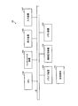
図1は、第1の実施の形態の情報処理システムにおけるシステム構成例を示す図である。この図1に示すように、第1の実施の形態の報処理システムは、1以上の画像形成装置20と、1以上のユーザ端末10を有している。図1の例は、画像形成装置20として、画像形成装置20a、画像形成装置20b・・・等の、複数の画像形成装置が設けられている例である。画像形成装置20及びユーザ端末10は、LAN(Local Area Network)又はインターネット等のネットワーク(有線又は無線の別は問わない)を介して、相互に通信可能に接続されている。
(First embodiment)
FIG. 1 is a diagram illustrating a system configuration example in the information processing system according to the first embodiment. As shown in FIG. 1, the information processing system according to the first embodiment includes one or more
画像形成装置20は、印刷、スキャン、コピー、及びFAX送受信等のうちの二以上の機能を一台の筐体によって実現する複合機である。但し、いずれか一つの機能を単体で有する機器が画像形成装置20として用いられてもよい。
The
ユーザ端末10は、画像形成装置20の操作パネルに表示される画面の構成を変更するために、ユーザによって利用されるコンピュータである。例えば、PC(Personal Computer)、携帯電話、スマートフォン、タブレット端末、又はPDA(Personal Digital Assistance)等が、ユーザ端末10として用いられてもよい。
The
図2は、第1の実施の形態におけるユーザ端末のハードウェア構成例を示す図である。図2のユーザ端末10は、それぞれバスBで相互に接続されているドライブ装置100、補助記憶装置102、メモリ装置103、CPU104、インタフェース装置105、表示装置106、及び入力装置107等を有する。
FIG. 2 is a diagram illustrating a hardware configuration example of the user terminal according to the first embodiment. The
ユーザ端末10での処理を実現するプログラムは、CD−ROM等の記録媒体101によって提供される。プログラムを記憶した記録媒体101がドライブ装置100にセットされると、プログラムが記録媒体101からドライブ装置100を介して補助記憶装置102にインストールされる。但し、プログラムのインストールは必ずしも記録媒体101から行う必要はなく、ネットワークを介して他のコンピュータからダウンロードしてもよい。補助記憶装置102は、インストールされたプログラムを格納すると共に、必要なファイルやデータ等を格納する。
A program for realizing processing in the
メモリ装置103は、プログラムの起動指示があった場合に、補助記憶装置102からプログラムを読み出して格納する。CPU104は、メモリ装置103に格納されたプログラムに従ってユーザ端末10に係る機能を実現する。インタフェース装置105は、ネットワークに接続するためのインタフェースとして用いられる。表示装置106はプログラムによるGUI(Graphical User Interface)等を表示する。入力装置107はキーボード及びマウス等で構成され、様々な操作指示を入力させるために用いられる。
The
図3は、第1の実施の形態における画像形成装置のハードウェア構成例を示す図である。図3において、画像形成装置20は、コントローラ21、スキャナ22、プリンタ23、モデム24、操作パネル25、ネットワークインタフェース26、及びSDカードスロット27等のハードウェアを有する。
FIG. 3 is a diagram illustrating a hardware configuration example of the image forming apparatus according to the first embodiment. 3, the
コントローラ21は、CPU211、RAM212、ROM213、HDD214、及びNVRAM215等を有する。ROM213には、各種のプログラムやプログラムによって利用されるデータ等が記憶されている。RAM212は、プログラムをロードするための記憶領域や、ロードされたプログラムのワーク領域等として用いられる。CPU211は、RAM212にロードされたプログラムを処理することにより、各種の機能を実現する。HDD214には、プログラムやプログラムが利用する各種のデータ等が記憶される。NVRAM215には、各種の設定情報等が記憶される。
The controller 21 includes a
スキャナ22は、原稿より画像データを読み取るためのハードウェア(画像読取手段)である。プリンタ23は、印刷データを印刷用紙に印刷するためのハードウェア(印刷手段)である。モデム24は、電話回線に接続するためのハードウェアであり、FAX通信による画像データの送受信を実行するために用いられる。操作パネル25は、ユーザからの入力の受け付けを行うためのボタン等の入力手段や、液晶パネル等の表示手段等を備えたハードウェアである。液晶パネルは、タッチパネル機能を有していてもよい。この場合、当該液晶パネルは、入力手段の機能をも兼ねる。ネットワークインタフェース26は、LAN等のネットワーク(有線又は無線の別は問わない。)に接続するためのハードウェアである。SDカードスロット27は、SDカード80に記憶されたプログラムを読み取るために利用される。すなわち、画像形成装置20では、ROM213に記憶されたプログラムだけでなく、SDカード80に記憶されたプログラムもRAM212にロードされ、実行されうる。なお、他の記録媒体(例えば、CD−ROM又はUSB(Universal Serial Bus)メモリ等)によってSDカード80が代替されてもよい。すなわち、SDカード80の位置付けに相当する記録媒体の種類は、所定のものに限定されない。この場合、SDカードスロット27は、記録媒体の種類に応じたハードウェアによって代替されればよい。
The
なお、操作パネル25は、専用の又は汎用的なスマートフォンやタブレット端末等、画像形成装置20からは独立したCPU及びOS(Operating System)を有する装置であってもよい。当該OSは、例えば、Android(登録商標)等、スマートフォンやダブレット端末等において一般的に利用されているものであってもよい。そうすることで、スマートフォンやタブレット端末等と同様に、表現豊かな画面を表示可能とすることができ、スマートフォンやタブレット端末等と同様の操作感を提供することができる。但し、他の装置によって、操作パネル25が実現されてもよい。
The operation panel 25 may be a device having a CPU and an OS (Operating System) independent from the
図4は、第1の実施の形態におけるユーザ端末及び画像形成装置の機能構成例を示す図である。図4において、画像形成装置20は、パネル制御部221、画面構成読出部22、及び画面構成書込部223等を有する。これら各部は、画像形成装置20にインストールされる1以上のプログラムが、CPU211に実行させる処理により実現される。画像形成装置20は、また、画面構成記憶部224を利用する。画面構成記憶部224は、例えば、HDD214、又は画像形成装置20にネットワークを介して接続可能な記憶装置等を用いて実現可能である。
FIG. 4 is a diagram illustrating a functional configuration example of the user terminal and the image forming apparatus according to the first embodiment. In FIG. 4, the
パネル制御部221は、操作パネル25への画面の表示を制御する。操作パネル25に表示される各種の画面のうち、初期画面又はホーム画面(以下、「初期画面」で統一する。)については、画面構成記憶部224に記憶されている画面構成情報に基づいて表示が行われる。画面構成情報とは、初期画面の構成を示す情報である。初期画面とは、例えば、画像形成装置20の操作の起点となる画面である。例えば、初期画面は、画像形成装置20が操作可能となったときに、最初に表示される画面であってもよい。画像形成装置20が操作可能となったときとは、例えば、画像形成装置20の起動の完了したとき、又は認証が必要とされる場合には、認証の成功したときである。
The
画面構成読出部222は、ユーザ端末10からの要求に応じ、画面構成記憶部224に記憶されている画面構成情報を読み出して、当該画面構成情報をユーザ端末10に送信する。画面構成書込部223は、ユーザ端末10から送信される画面構成情報を、画面構成記憶部224に書き込む。
In response to a request from the
一方、ユーザ端末10は、画面構成取得部11、画面再現部12、画面構成変更部13、画面構成送信部14、及び画面構成保存部15等を有する。これら各部は、ユーザ端末10にインストールされる1以上のプログラムが、CPU104に実行させる処理により実現される。ユーザ端末10は、また、画面構成記憶部16を利用する。画面構成記憶部16は、例えば、補助記憶装置102、又はユーザ端末10にネットワークを介して接続可能な記憶装置等を用いて実現可能である。
On the other hand, the
画面構成取得部11は、変更対象又は編集対象とする画面構成情報を、いずれかの画像形成装置20、又は画面構成記憶部16から取得する。画面再現部12は、パネル制御部221による、画面構成情報に基づく初期画面の表示処理を模倣する。すなわち、画面再現部12は、画面構成取得部11によって取得された画面構成情報に基づいて、画像形成装置20における表示態様と同様の態様で、初期画面を表示する。画面構成変更部13は、表示された初期画面に対する変更指示に応じて、画面構成情報を変更する。画面構成送信部14は、変更後の画面構成情報を、指定された画像形成装置20に送信する。画面構成保存部15は、変更後の画面構成情報を、画面構成記憶部16に保存する。
The screen configuration acquisition unit 11 acquires screen configuration information to be changed or edited from any one of the
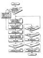
以下、ユーザ端末10が実行する処理手順について説明する。図5は、ユーザ端末が実行する処理手順の一例を説明するためのフローチャートである。なお、図5の説明において、ユーザは、ユーザ端末10を操作する。
Hereinafter, a processing procedure executed by the
例えば、ユーザによって、画面構成情報の取得指示が入力されると、画面構成取得部11は、当該取得指示において指定された画面情報の取得先が画像形成装置20であるか、又はユーザ端末10のローカルファイルであるか否かを判定する(S101)。ローカルファイルとは、例えば、画面構成記憶部16に記憶されているファイルをいう。但し、画面構成情報は、ファイル以外のデータ形式で画面構成記憶部16に記憶されていてもよい。
For example, when an acquisition instruction for screen configuration information is input by the user, the screen configuration acquisition unit 11 determines whether the acquisition destination of the screen information specified in the acquisition instruction is the
取得先が画像形成装置20である場合(S101:Yes)、画面構成取得部11は、取得先の画像形成装置20のIPアドレスの入力をユーザから受け付ける(S102)。例えば、画面構成取得部11が、IPアドレスの入力用の画面を表示し、当該画面を介してIPアドレスの入力が受け付けられてもよい。なお、IPアドレス以外に、URL(Uniform Resource Locator)等、他の識別情報が入力されてもよい。
If the acquisition destination is the image forming apparatus 20 (S101: Yes), the screen configuration acquisition unit 11 receives an input of the IP address of the acquisition destination
続いて、画面構成取得部11は、入力されたIPアドレスに係る画像形成装置20から、当該画像形成装置20の画面構成記憶部224に記憶されている画面構成情報を取得する(S103)。より詳しくは、画面構成取得部11は、画面構成情報の取得要求を当該画像形成装置20に送信する。当該画像形成装置20の画面構成読出部222は、当該取得要求に応じ、画面構成記憶部224に記憶されている画面構成情報を取得し、取得された画面構成情報を、画面構成取得部11に返信する。
Subsequently, the screen configuration acquisition unit 11 acquires screen configuration information stored in the screen configuration storage unit 224 of the
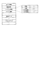
図6は、画面構成情報の構成例を示す図である。図6では、便宜上、画面構成情報が表形式によって表現されているが、例えば、XML(eXtensible Markup Language)等を利用して画面構成情報が記述されてもよい。 FIG. 6 is a diagram illustrating a configuration example of screen configuration information. In FIG. 6, for convenience, the screen configuration information is expressed in a table format. However, for example, the screen configuration information may be described using XML (eXtensible Markup Language) or the like.
図6において、画面構成情報は、例えばモデル情報、壁紙情報、レイアウト情報、アイコン情報、壁紙データ、及びアイコンデータ等を含む。但し、これら以外の情報が、画面構成情報に含まれてもよい。 In FIG. 6, the screen configuration information includes model information, wallpaper information, layout information, icon information, wallpaper data, icon data, and the like. However, information other than these may be included in the screen configuration information.
モデル情報は、当該画面構成情報を適用可能な(当該画面構成情報が有効な)画像形成装置20のモデル(機種)に関する情報である。例えば、モデル名等がモデル情報に含まれる。
The model information is information related to the model (model) of the
壁紙情報は、初期画面の壁紙(背景)として利用される画像データ(以下、「壁紙データ」という。)を示す情報である。例えば、後述される壁紙データのうちのいずれか一つの壁紙データの識別情報(以下、「壁紙ID」という。)が、壁紙情報に含まれる。 The wallpaper information is information indicating image data (hereinafter referred to as “wallpaper data”) used as the wallpaper (background) of the initial screen. For example, the wallpaper information includes identification information (hereinafter referred to as “wallpaper ID”) of any one of wallpaper data to be described later.
レイアウト情報は、初期画面における表示部品(以下、「アイコン」とする。)の配置に関する情報である。 The layout information is information relating to the arrangement of display components (hereinafter referred to as “icons”) on the initial screen.
アイコン情報は、初期画面に配置されるアイコンごとに、画面構成情報に含まれる。例えば、各アイコン情報には、アイコンの配置位置等を示す情報が含まれる。 The icon information is included in the screen configuration information for each icon arranged on the initial screen. For example, each icon information includes information indicating an icon arrangement position and the like.
壁紙データは、初期画面の壁紙に利用可能な1以上の画像データである。画面構成情報には、1以上の壁紙データのそれぞれが、例えば、エンコードされて列挙されている。各壁紙データには、壁紙IDが対応付けられている。 The wallpaper data is one or more image data that can be used for the wallpaper of the initial screen. In the screen configuration information, one or more pieces of wallpaper data are encoded and listed, for example. Each wallpaper data is associated with a wallpaper ID.
アイコンデータは、デフォルトとして含まれているアイコンの画像データ(以下、「アイコンデータ」という。)である。画面構成情報には、例えば、画像形成装置20において標準のアプリケーションプログラムのそれぞれに対するアイコンデータが、例えば、エンコードされて列挙されている。各アイコンデータには、識別情報(以下、「アイコンID」という。)が対応付けられている。
The icon data is icon image data (hereinafter referred to as “icon data”) included as a default. In the screen configuration information, for example, icon data for each of the standard application programs in the
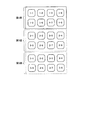
図6において、レイアウト情報は、列数、行数、X方向面数、Y方向面数等を含む。列数は、一つの面における水平方向において配置可能なアイコンの数である。行数は、一つの面における垂直方向において配置可能なアイコンの数である。X方向面数は、水平方向の面数である。Y方向面数は、垂直方向の面数である。ここで、「面」とは、例えば、スワイプ操作やスクロール操作等によって切り替え可能な表示範囲(表示領域)の単位である。図6では、列数=4,行数=2、X方向面数=1、Y方向面数=3とされている。この場合、初期画面は、図7に示されるようなレイアウトを有する。 In FIG. 6, the layout information includes the number of columns, the number of rows, the number of X-direction surfaces, the number of Y-direction surfaces, and the like. The number of columns is the number of icons that can be arranged in the horizontal direction on one surface. The number of rows is the number of icons that can be arranged in the vertical direction on one surface. The number of faces in the X direction is the number of faces in the horizontal direction. The number of Y direction surfaces is the number of surfaces in the vertical direction. Here, the “surface” is a unit of a display range (display area) that can be switched by, for example, a swipe operation or a scroll operation. In FIG. 6, the number of columns = 4, the number of rows = 2, the number of planes in the X direction = 1, and the number of planes in the Y direction = 3. In this case, the initial screen has a layout as shown in FIG.
図7は、初期画面のレイアウトの一例を示す図である。図7では、垂直方向に、第1面から第3面の3つの面が示されている。同時に表示可能な範囲は、1つの面である。各面は、2行4列分(8個分)の、アイコンの配置位置を含む。各配置位置は、「<面番号>−<位置番号>」の形式で表現される座標値を有する。面番号は、各面の識別番号である。位置番号は、面単位の通し番号である。すなわち、図7では、面ごとに8個分の配置位置を含むため、位置番号は、1〜8の値を有する。 FIG. 7 is a diagram illustrating an example of the layout of the initial screen. In FIG. 7, three surfaces from the first surface to the third surface are shown in the vertical direction. The range that can be displayed simultaneously is one surface. Each plane includes icon arrangement positions corresponding to 2 rows and 4 columns (eight). Each arrangement position has a coordinate value expressed in a format of “<surface number> − <position number>”. The surface number is an identification number of each surface. The position number is a serial number in units of planes. That is, in FIG. 7, since the eight arrangement positions are included for each surface, the position number has a value of 1 to 8.
また、画面構成情報の一部である各アイコン情報は、例えば、図8に示されるような構成を有する。図8は、1つのアイコン情報の構成例を示す図である。(1)は、アプリケーションプログラムに対応するアイコンのアイコン情報の構成例である。(2)は、ウィジェット(widget)に対応するアイコンのアイコン情報の構成例である。(3)は、ショートカットに対応するアイコンのアイコン情報の構成例である。すなわち、アイコン情報は、アイコンに対応する実体に応じて構成が異なる。但し、(1)〜(3)において、タイプ及び配置位置は、共通項目である。 Each icon information that is a part of the screen configuration information has a configuration as shown in FIG. 8, for example. FIG. 8 is a diagram illustrating a configuration example of one icon information. (1) is a configuration example of icon information of an icon corresponding to an application program. (2) is a configuration example of icon information of an icon corresponding to a widget (widget). (3) is a configuration example of icon information of an icon corresponding to a shortcut. That is, the configuration of the icon information differs depending on the entity corresponding to the icon. However, in (1) to (3), the type and the arrangement position are common items.
タイプは、アイコンに対応する実体の種別を示す情報である。例えば、「application」は、アプリケーションプログラムを示す。「widget」は、ウィジェットを示す。「url」は、URL(Uniform Resource Locator)へのショートカットを示す。配置位置は、図7に示した座標値によって、アイコンの配置位置を示す項目である。(2)では、(1−3,1−7)が配置位置とされている。これは、「1−3」と「1−7」との中央が配置位置であることを示す。また、配置位置には、(1−7,(+0%,+30%))といった指定も可能である。これは、「1−7」の配置位置に対して、x方向に0%のずれを有し、y方向に+30%のずれを有する配置位置を示す。また、非表示とされるアイコンの配置位置は、「0−0」とされる。 The type is information indicating the type of entity corresponding to the icon. For example, “application” indicates an application program. “Widget” indicates a widget. “Url” indicates a shortcut to a URL (Uniform Resource Locator). The arrangement position is an item indicating the icon arrangement position based on the coordinate values shown in FIG. In (2), (1-3, 1-7) is an arrangement position. This indicates that the center of “1-3” and “1-7” is the arrangement position. In addition, it is possible to specify (1-7, (+ 0%, + 30%)) as the arrangement position. This indicates an arrangement position having a deviation of 0% in the x direction and a deviation of + 30% in the y direction with respect to the arrangement position of “1-7”. The arrangement position of the non-displayed icon is “0-0”.
(1)のアイコン情報は、更に、アイコンID、アプリケーションID、及び名前等を含む。アイコンIDは、画面構成情報に含まれているいずれかのアイコンデータに対するアイコンIDである。すなわち、当該アイコン情報に係るアイコンは、アイコンIDに係るアイコンデータによって表示される。アプリケーションIDは、このアイコンに対応するアプリケーションプログラムのIDであり、画像形成装置20において、アイコンが操作されたときに利用される。名前は、アイコンの表示名である。
The icon information (1) further includes an icon ID, an application ID, a name, and the like. The icon ID is an icon ID for any icon data included in the screen configuration information. That is, the icon related to the icon information is displayed by icon data related to the icon ID. The application ID is an ID of an application program corresponding to this icon, and is used when the icon is operated in the
(2)のアイコン情報は、更に、アプリケーションID及びアイコンデータを含む。アプリケーションIDは、このアイコンに対応するウィジェットのIDである。アイコンデータは、当該アイコン情報に係るアイコンを表示するためのアイコンデータの実体が、例えば、エンコードされたものである。 The icon information (2) further includes an application ID and icon data. The application ID is the ID of the widget corresponding to this icon. The icon data is, for example, encoded data of icon data for displaying an icon related to the icon information.
(3)のアイコン情報は、更に、url及びアイコンデータを含む。urlは、参照先のURLである。アイコンデータは、当該アイコン情報に係るアイコンを表示するためのアイコンデータの実体が、例えば、エンコードされたものである。 The icon information (3) further includes url and icon data. url is the URL of the reference destination. The icon data is, for example, encoded data of icon data for displaying an icon related to the icon information.
図5のステップS103では、図6〜図8において説明したような構成を有する画面構成情報が取得される。 In step S103 of FIG. 5, screen configuration information having the configuration described in FIGS. 6 to 8 is acquired.
一方、取得先がローカルファイルである場合(S101:No)、画面構成取得部11は、ファイル名の入力をユーザから受け付ける(S104)。続いて、画面構成取得部11は、画面構成記憶部16に記憶されているファイルのうち、入力されたファイル名に係るファイルから画面構成情報を取得する(S105)。ここで取得される画面構成情報も、図6〜図8において説明したような構成を有する。なお、ファイル名ではなく、画像形成装置20のモデル名(機種名)が入力されてもよい。この場合、当該モデル名に係る画面構成情報が取得されてもよい。
On the other hand, when the acquisition destination is a local file (S101: No), the screen configuration acquisition unit 11 receives an input of a file name from the user (S104). Subsequently, the screen configuration acquisition unit 11 acquires screen configuration information from the file associated with the input file name among the files stored in the screen configuration storage unit 16 (S105). The screen configuration information acquired here also has the configuration described with reference to FIGS. Note that the model name (model name) of the
なお、ステップS104及びS105は、例えば、画像形成装置20が納品されていない状態において、納品予定の画像形成装置20に関して予め画面構成情報をカスタマイズしておきたい場合に便利な処理手順である。又は、ステップS104及びS105は、或る画像形成装置20に関して既にカスタマイズされた画面構成情報を流用して、他の画像形成装置20に関する画面構成情報を生成する場合にも有効である。
Steps S104 and S105 are convenient processing procedures when, for example, it is desired to customize the screen configuration information in advance for the
ステップS103又はS105に続いて、画面再現部12は、取得された画面構成情報に基づいて、初期画面を含む編集画面を表示装置106に表示する(S106)。
Subsequent to step S103 or S105, the
図9は、編集画面の表示例を示す図である。図9において、編集画面510は、表示領域511及びメニュー領域512等を含む。表示領域511は、画面構成情報に基づいて、初期画面610が再現される領域である。すなわち、表示領域511には、画像形成装置20の操作パネル25において表示される態様と同じ態様で、初期画面610が表示される。メニュー領域512は、各種の操作を受け付けるための領域である。
FIG. 9 is a diagram illustrating a display example of the editing screen. In FIG. 9, the
初期画面610は、Copy、Scan、Fax、Doc、Address、Config、Weather等の7個のアイコンを含む。画像形成装置20において初期画面610が表示されている状態において、いずれかのアイコンが選択されると、当該アイコンのアイコン情報に含まれているアプリケーションID又はurlに対応した処理が実行される。
The initial screen 610 includes seven icons such as Copy, Scan, Fax, Doc, Address, Config, and Weather. If any icon is selected while the initial screen 610 is displayed in the
編集画面510を介して、初期画面610の構成についての変更指示がユーザによって入力されると(S107:Yes)、画面構成変更部13は、変更指示に応じた変更を、画面構成情報に適用する(S108)。例えば、ユーザは、表示領域511に表示されている初期画面610上のアイコンをドラッグして、アイコンの位置を変更することができる。ドラッグした先に、別のアイコンが有る場合、ドラッグされたアイコンと、当該別のアイコンとの配置位置が入れ替わる。この場合、配置位置が変更されたアイコンのアイコン情報の配置位置の値が変更される。また、いずれかのアイコンが選択された状態でDeleteキーが押下されると、画面構成変更部13は、当該アイコンのアイコン情報の配置位置の値を「0−0」に変更する。
When an instruction to change the configuration of the initial screen 610 is input by the user via the editing screen 510 (S107: Yes), the screen
また、いずれかのアイコンに対して右クリックが行われると、画面構成変更部13は、「アイコンの変更」及び「名前の変更」等のメニュー項目を含むコンテキストメニューを表示する。当該コンテキストメニューにおいて、「アイコンの変更」が選択されると、アイコンデータの変更が可能となる。例えば、ユーザ端末10の補助記憶装置102に記憶されているアイコンデータを、画面構成情報のアイコンデータとして追加することができる。追加されたアイコンデータを、右クリックされているアイコンに対するアイコンデータとすることができる。
Further, when a right click is performed on any of the icons, the screen
また、「名前の変更」が選択されると、アイコン情報の名前の変更が可能となる。なお、「アイコンの設定を元に戻す」というメニュー項目がコンテキストメニューに含まれてもよい。当該メニュー項目が選択された場合、画面構成変更部13は、アイコンデータの変更や、名前の変更等を元に戻してもよい。
Also, when “change name” is selected, the name of the icon information can be changed. Note that a menu item “restore icon settings” may be included in the context menu. When the menu item is selected, the screen
また、メニュー領域512が操作されることにより、画面構成変更部13は、画面構成情報に含まれている壁紙データの一覧を、メニュー領域512に表示する。当該一覧の中からいずれかの壁紙データが選択されると、選択された壁紙データの壁紙IDが、画面構成情報の壁紙情報に対して上書きされる。その結果、初期画面610の壁紙が変更される。また、ユーザ端末10の補助記憶装置102に記憶されている画像データが、画面構成情報の壁紙データに追加されてもよい。そうすることで、補助記憶装置102に記憶されている画像データを、初期画面610の壁紙データとして利用することができる。
In addition, when the
以上のような変更(編集)が行われることで、例えば、初期画面610は、図10に示されるように変更される。図10は、変更後の初期画面を含む編集画面の表示例を示す図である。 By performing the change (editing) as described above, for example, the initial screen 610 is changed as shown in FIG. FIG. 10 is a diagram illustrating a display example of an editing screen including the changed initial screen.
図10の編集画面510の表示領域511には、変更後の初期画面610aが示されている。初期画面610aでは、アイコンの配置位置の変更、アイコンデータの変更、壁紙変更等が行われている。具体的には、"Fax"及び"Doc"のアイコンのアイコンデータが変更され、Configのアイコンが削除されている。"Doc"のアイコンについては、名前も変更されている。また、"Weather"のアイコンは大きさも変更されている。
In the
続いて、変更の終了が指示され(S107:No)、変更後の画面構成情報に関して送信先のIPアドレスが入力されると(S109:Yes)、画面構成送信部14は、入力されたIPアドレスに係る画像形成装置20に、変更後の画面構成情報を送信する(S110)。当該画像形成装置20の画面構成書込部223は、当該画面構成情報を受信すると、画面構成記憶部224に当該画面構成情報を記憶する。このとき、元の画面構成情報は、受信された画面構成情報によって上書きされてもよい。
Subsequently, when the end of the change is instructed (S107: No), and the IP address of the transmission destination is input regarding the changed screen configuration information (S109: Yes), the screen
なお、ステップS110は、複数回繰り返されてもよい。すなわち、同一の画面構成情報が、複数の画像形成装置20に適用されてもよい。
Note that step S110 may be repeated a plurality of times. That is, the same screen configuration information may be applied to a plurality of
IPアドレスの入力が終了し(S109:No)、画面構成情報の保存指示が入力されると(S111:Yes)、画面構成保存部15は、変更後の画面構成情報を、画面構成記憶部16に記憶する(S112)。例えば、ステップS104及びS105が実行されて、変更対象の画面構成情報が画面構成記憶部16から取得されたものである場合には、上書き保存が指示されてもよい。この場合、画面構成保存部15は、変更後の画面構成情報によって、元の画面構成情報を上書きする。また、名前を付与して保存する場合には、画面構成保存部15は、ユーザによって入力された名前に対応付けて、変更後の画面構成情報を画面構成記憶部16に記憶する。画面構成記憶部16に記憶された画面構成情報は、次回のステップS104及びS105において、選択候補となる。また、画面構成記憶部16に記憶された画面構成情報に基づいて、別の画像形成装置20に対する画面構成情報が生成されてもよい。
When the input of the IP address is completed (S109: No), and a screen configuration information storage instruction is input (S111: Yes), the screen configuration storage unit 15 displays the changed screen configuration information as the screen
なお、初期画面の構成をユーザごとに異なるものとしたい場合、画面構成情報は、ユーザごとの識別情報(例えば、ユーザID)に対応付けられて、画面構成記憶部224又は画面構成記憶部16に記憶されるようにしてもよい。例えば、ユーザIDが、画面構成情報に含まれるようにしてもよい。この場合、図5の処理の開始時において、画面構成情報の取得先と共に、ユーザIDが指定されてもよい。画面構成取得部11は、指定されたユーザIDに対応する画面構成情報を取得してもよい。
When it is desired to make the configuration of the initial screen different for each user, the screen configuration information is associated with identification information (for example, user ID) for each user and stored in the screen configuration storage unit 224 or the screen
上述したように、第1の実施の形態によれば、ユーザは、ユーザ端末10を利用して、初期画面の画面構成情報を変更することができる。変更後の画面構成情報は、元の画面構成情報の取得先の画像形成装置20のみならず、他の画像形成装置20にも送信して適用することができる。すなわち、1つの画面構成情報の変更によって、複数の画像形成装置20の初期画面の構成を変更することができる。従って、画像形成装置20において表示される画面の構成を変更するための操作の負担を軽減することができる。
As described above, according to the first embodiment, the user can change the screen configuration information of the initial screen using the
(第2の実施の形態)
次に、第2の実施の形態の情報処理システムの説明をする。この第2の実施の形態の情報処理システムは、ユーザ端末10において、1台の画像形成装置20の設定結果となる操作部画像を取得し、1台目の画像形成装置20の設定結果が適切であるか否かを、操作パネル25の模倣動作を行うエミュレータ上で検証する。ユーザが、この検証結果を承認(OK)すると、ユーザ端末10は、2台目以降となる画像形成装置20から設定結果となる操作部画像を取得し、承認した比較画像と比較する。これにより、複数台の画像形成装置20に対して、それぞれ設定情報を反映させる面倒な作業を大幅に削減でき、作業時間を短縮化できる。
(Second Embodiment)
Next, an information processing system according to the second embodiment will be described. In the information processing system according to the second embodiment, the
図11は、第2の実施の形態の情報処理システムのユーザ端末10のCPU104が、補助記憶装置102に記憶されているユーザ端末10用の設定アプリケーションプログラム(設定アプリ)を実行することで実現される各機能の機能ブロック図である。この図11に示すように、ユーザ端末10のCPU104は、設定アプリを実行することで、入力処理部701、取得部702、エミュレータ部703、変更処理部704、通信制御部705、照合処理部706、判別部707、差分検出部708、表示制御部709及び記憶制御部710として機能する。エミュレータ部703は、模倣部の一例である。照合処理部706及び差分検出部708は、比較部の一例である。表示制御部は、出力部の一例である。
FIG. 11 is realized by the CPU 104 of the
エミュレータ部703は、対象機器(例えば、本実施の形態で言う画像形成装置20)におけるアプリケーションや、対象機器のハードウェア等の動作を模倣(エミュレート又はシミュレート等)する。したがって、エミュレータ部703は、対象機器と同様の動作環境を提供することができる。なお、エミュレータ部703は、ユーザ端末10にインストールされたプログラムが、CPU104に実行させる処理により実現される。また、本実施の形態において、エミュレート又はエミュレータには、シミュレートの意味も包含される。
The emulator unit 703 imitates (emulates or simulates) an operation of an application in the target device (for example, the
入力処理部701は、ユーザから入力装置107を介して入力される画像形成装置20のIP(Internet Protocol)アドレス等の取得処理を行う。取得部702は、補助記憶装置102に記憶されている設定情報し、又は、ユーザから指定されたIPアドレスの画像珪藻装置20から設定情報を取得する。エミュレータ部703は、画像形成装置20の例えば操作パネル25の動作を模倣する。変更処理部704は、取得した設定情報をユーザの操作等に応じて変更処理する。
The input processing unit 701 performs an acquisition process such as an IP (Internet Protocol) address of the
通信制御部705は、ユーザ端末10と画像形成装置20との間の通信制御を行う。照合処理部706は、変更処理した設定情報を画像処理装置20に反映させることで形成される表示画面の画像を比較画像と、変更処理した設定情報を他の画像処理装置20に反映させることで形成される表示画面の画像とを比較(照合)する。判別部707は、照合処理部706の照合結果に基づいて、他の画像処理装置20に対する変更処理した設定情報の反映は、成功したか否かを判別する。
The
差分検出部708は、上述の比較画像と、変更処理した設定情報が反映された他の画像処理装置20で形成される表示画面の画像との差分となる画像を検出する。表示制御部709は、上述の比較画像と、変更処理した設定情報が反映された他の画像処理装置20で形成される表示画面の画像との差分となる画像等を表示する。記憶制御部710は、画像処理装置20に対する反映が成功した設定情報を、補助記憶装置102等の記憶部に記憶する。
The
なお、この例では、入力処理部701〜記憶制御部710をソフトウェアで実現することとしたが、入力処理部701〜記憶制御部710のうち、一部又は全部を、IC(Integrated Circuit)等のハードウェアで実現してもよい。また、本明細書で説明するCPU104等のCPUとしては、ソフトウェアによって各機能を実行するようプログラムされたプロセッサ、及び、各機能を実行するよう設計されたASIC(Application Specific Integrated Circuit)、IC(Integrated Circuit)又は回路モジュールなどのハードウェアを含むものとする。 In this example, the input processing unit 701 to the storage control unit 710 are realized by software. However, part or all of the input processing unit 701 to the storage control unit 710 may be an IC (Integrated Circuit) or the like. It may be realized by hardware. A CPU such as the CPU 104 described in this specification includes a processor programmed to execute each function by software, an application specific integrated circuit (ASIC) and an IC (Integrated) designed to execute each function. Circuit) or hardware such as a circuit module.
また、ユーザ端末10用の設定アプリは、インストール可能な形式または実行可能な形式のファイルでCD−ROM、フレキシブルディスク(FD)などのコンピュータ装置で読み取り可能な記録媒体に記録して提供してもよい。また、CD−R、DVD(Digital Versatile Disk)、ブルーレイディスク(登録商標)、半導体メモリなどのコンピュータ装置で読み取り可能な記録媒体に記録して提供してもよい。また、ユーザ端末10用の設定アプリは、インターネット等のネットワーク経由でインストールする形態で提供してもよい。また、ユーザ端末10用の設定アプリは、機器内のROM等に予め組み込んで提供してもよい。
In addition, the setting application for the
次に、図12は、第2の実施の形態の情報処理システムの画像形成装置20のCPU211が、例えばHDD214等の記憶部に記憶されている画像形成装置20用の設定アプリケーションプログラム(設定アプリ)を実行することで実現される各機能の機能ブロック図である。この図12に示すように、画像形成装置20のCPU211は、設定アプリを実行することで、通信制御部751、記憶制御部752、設定動作部753及び動作画像形成部754として機能する。
Next, FIG. 12 illustrates a setting application program (setting application) for the
通信制御部751は、画像形成装置20の設定情報及び変更された設定情報に対応する動作画像をユーザ端末10に送信する等、画像形成装置20とユーザ端末10との間の通信制御を行う。記憶制御部752は、NVRAM215に記憶されている設定情報を、ユーザ端末10から送信された設定情報に変更処理(書き換え処理)することで、変更された設定情報を記憶制御部752に反映させる。設定動作部753は、変更された設定情報に対応する箇所を、変更された設定情報に基づいて動作させる。動作画像形成部754は、変更された設定情報に基づいて動作することで得られる動作画面の画像である動作画像を形成する。
The
なお、通信制御部751〜動作画像形成部754は、をソフトウェアで実現することとしたが、通信制御部751〜動作画像形成部754のうち、一部又は全部を、IC(Integrated Circuit)等のハードウェアで実現してもよい。また、本明細書で説明するCPU211等のCPUとしては、ソフトウェアによって各機能を実行するようプログラムされたプロセッサ、及び、各機能を実行するよう設計されたASIC(Application Specific Integrated Circuit)、IC(Integrated Circuit)又は回路モジュールなどのハードウェアを含むものとする。
Note that the
また、画像形成装置20用の設定アプリは、インストール可能な形式または実行可能な形式のファイルでCD−ROM、フレキシブルディスク(FD)などのコンピュータ装置で読み取り可能な記録媒体に記録して提供してもよい。また、CD−R、DVD(Digital Versatile Disk)、ブルーレイディスク(登録商標)、半導体メモリなどのコンピュータ装置で読み取り可能な記録媒体に記録して提供してもよい。また、画像形成装置20用の設定アプリは、インターネット等のネットワーク経由でインストールする形態で提供してもよい。また、画像形成装置20用の設定アプリは、機器内のROM等に予め組み込んで提供してもよい。
The setting application for the
図13のフローチャートに、画像形成装置20に対する変更処理した設定情報の反映動作、及び、反映させた設定情報の検証動作の流れを示す。この図13のフローチャートは、ユーザ端末10の設定アプリが起動操作されることで、ステップS201から処理が開始される。まず、ユーザは、入力装置107を操作することで、画像形成装置20から設定情報を取得するか、又は、補助記憶装置102に記憶されている設定情報を取得するかを指定する。図11に示す入力処理部701は、ユーザにより入力装置107を介して指示された設定情報の取得先(画像形成装置20又は補助記憶装置102)を示す情報の入力処理を行う。そして、取得部702は、ステップS201において、設定情報を画像形成装置20から取得する指示が、ユーザからされたか否かを判別する。設定情報を画像形成装置20から取得する指示が、ユーザからされたと判別した場合は、ステップS202に処理を進め、設定情報を画像形成装置20から取得する指示が、ユーザからされていないと判別した場合は、ステップS214に処理を進める。
The flowchart of FIG. 13 shows the flow of the operation of reflecting the changed setting information on the
設定情報を画像形成装置20から取得する場合、ユーザは、設定情報を取得する画像形成装置(対象となる画像形成装置)20のIPアドレスを入力する。取得部702は、ステップS202において、ユーザから入力されたIPアドレスを取得する。また、取得部702は、ステップS203において、ユーザから入力されたIPアドレスに対応する画像形成装置20に対して、通信制御部705を介してアクセスし、設定情報の転送要求を行う。画像形成装置20の記憶制御部752は、NVRAM215に記憶されている設定情報を読み出す。そして、通信制御部751が、読み出された設定情報をユーザ端末10に送信する。これにより、ユーザ端末10の取得部702は、ユーザにより指定された画像形成装置20の設定情報を取得する。
When acquiring the setting information from the
ここで、ユーザが設定情報を変更処理する画像形成装置20がネットワークに接続されている場合、上述のようにネットワークを介して画像形成装置20の設定情報を取得できる。しかし、納品前の画像形成装置20の設定情報を、ネットワークを介して変更処理することは困難である。この場合、同じモデルの画像形成装置20の設定情報を、事前に取得して補助記憶装置102に記憶しておく。そして、ステップS214において、取得部702が、補助記憶装置102に記憶されている設定情報を取得する。なお、ステップS212及びステップS213の説明で後述するが、変更処理が施された設定情報は、補助記憶装置102に保存される。このため、以前、変更処理を施した設定情報を、さらに変更処理する場合も、取得部702は、補助記憶装置102から設定情報を取得する。
Here, when the
次に、このように画像形成装置20又は補助記憶装置102から設定情報が取得されると、取得された設定情報に基づいて、エミュレータ部703が画像形成装置の模倣動作を行う。例えば、取得された設定情報が、画像形成装置20の操作パネル25の設定情報であった場合、エミュレータ部703は、取得された設定情報に基づいて、操作パネル25の表示画面を表示装置106に表示する等の模倣動作を行う。ユーザは、所望の表示内容の表示画面が得られるように、模倣動作で表示される表示画面を見ながら、設定情報を所望の値に変更操作する。変更処理部704は、ステップS204において、ユーザの変更操作に応じて、設定情報を変更処理する。
Next, when the setting information is acquired from the
次に、ユーザは、変更処理が完了すると、入力装置107を介して設定情報の変更完了操作を行う。通信制御部705は、変更完了操作が行われると、ステップS205において、変更処理された設定情報を、ステップS202で入力されたIPアドレスに対応する画像形成装置20に送信する。
Next, when the change process is completed, the user performs a setting information change completion operation via the
図12に示す画像形成装置20の記憶制御部752は、ユーザ端末10から送信された、変更処理された設定情報を、NVRAM215に記憶されている元の設定情報に上書き処理する。設定動作部753は、上書き処理された設定情報(変更処理された設定情報)に対応する箇所を、上書き処理された設定情報に基づいて動作させる。動作画像形成部754は、上書き処理された設定情報に対応する動作画面の画像である動作画像を形成する。例えば、操作パネル25の設定情報が上書き処理された場合、設定動作部753は、上書き処理された設定情報に基づいて操作パネル25を動作させる。そして、動作画像形成部754は、設定情報に基づいて動作した操作パネル25の動作画像を形成する。通信制御部751は、動作画像をユーザ端末10に送信する。
The
図11に示すユーザ端末10の照合処理部706は、ステップS206において、画像形成装置20から送信された動作画像と、変更処理した設定情報を反映した他の画像形成装置20から得られた動作画像とを照合することで、変更処理した設定情報に対応する各画像形成装置20の動作検証等を行う。照合処理部706の詳しい動作は、図14のフローチャートを用いて後述する。
In step S206, the collation processing unit 706 of the
ユーザは、照合処理の結果を見て、変更処理した設定情報により、画像形成装置20において所望の動作が得られていると判断した場合、入力装置107を介して、反映成功を示す所定の操作を行う。判別部707は、反映成功を示す所定の操作を検出した場合、反映成功の判別信号を出力し、反映成功を示す所定の操作を検出しない場合は、反映失敗の判別信号を出力する。判別部707から、反映失敗の判別信号が出力された場合(ステップS207:No)、表示制御部709は、ステップS208において、表示装置106に、例えば「設定に失敗しました」等の反映失敗の旨の表示を行う。これにより、図13のフローチャートの処理が終了する。
When the user sees the result of the collation process and determines that the desired operation is obtained in the
これに対して、ユーザは、反映が成功した設定情報を他の画像形成装置20に設定する場合、入力装置107を介して、設定情報を反映させる画像形成装置20を指定する。判別部707は、ステップS209において、ユーザからの指定操作の有無を判別することで、設定情報を反映させる画像形成装置20が指定されたか否かを判別する。判別部707により、設定情報を反映させる画像形成装置20が指定されたと判別されると(ステップS209:Yes)、処理がステップS202に戻り、ユーザからIPアドレスが入力された画像形成装置20に対して、上述の変更処理が施された設定情報が反映(設定)される。
On the other hand, when setting the setting information successfully reflected in another
一方、判別部707により、設定情報を反映させる画像形成装置20が指定されないと判別されると(ステップS209:No)、処理がステップS210に進み、差分検出部708が、上述の比較画像と、変更処理した設定情報が反映された他の画像処理装置20で形成される表示画面の画像との間に、差分となる画像(差分画像)が存在するか否かを判別する。差分となる画像が存在すると判別された場合(ステップS210:Yes)、ステップS211に処理が進み、表示制御部709が、差分画像を表示装置106に表示する。詳しくは後述するが、ユーザは、表示された差分画像に基づいて、他の画像形成装置20に対して、変更した設定情報が正確に反映されているか否かを判別する。
On the other hand, when the
次に、差分画像を保存する場合、ユーザは、入力装置107を介して、差分画像の保存操作を行う。ステップS212では、記憶制御部710が、差分画像の保存操作の有無を監視する。差分画像の保存操作が検出されない場合は(ステップS212:No)、そのまま図13のフローチャートの処理を終了する。
Next, when saving the difference image, the user performs a difference image saving operation via the
これに対して、差分画像の保存操作が検出された場合は(ステップS212:Yes)、ステップS213に処理が進み、記憶制御部710が、指定されたファイル名で差分画像を補助記憶装置102等の記憶部に保存する。これにより、図13のフローチャートの処理が終了する。
On the other hand, when a difference image saving operation is detected (step S212: Yes), the process proceeds to step S213, and the storage control unit 710 uses the designated file name to store the difference image in the
なお、この例では差分画像を機器毎に表示して、ユーザに確認させる形を取っているが、差分画像を機器毎に関連付けて保存しておき、対象全機器への反映処理を行った後、ユーザに確認を要求するものであってもよい。 In this example, the difference image is displayed for each device and the user confirms it. However, after the difference image is stored in association with each device and reflected on all the target devices, The user may be requested to confirm.
次に、図14のフローチャートを用いて、図13のステップS206における照合処理を詳細に説明する。なお、一例として、画像形成装置20の操作パネル25の設定情報を変更した例を用いて、この図14のフローチャートの説明をする。まず、ステップS301では、照合処理部706が、変更された設定情報に基づいて動作した操作パネル25の操作部画像を画像形成装置20から取得する。
Next, the collating process in step S206 in FIG. 13 will be described in detail using the flowchart in FIG. As an example, the flowchart of FIG. 14 will be described using an example in which the setting information of the operation panel 25 of the
ステップS302では、照合処理部706が、変更した設定情報に対応する操作部画像を取得する、最初の画像形成装置20であるか否か(1台目の画像形成装置20であるか否か)を判別する。最初の画像形成装置20である場合(ステップS302:Yes)、照合処理部706は、ステップS303において、表示制御部709を介して表示装置106に、操作部画像を表示する。また、照合処理部706は、操作部画像と共に、反映結果が成功したとユーザが判断したときに操作する成功ボタン、及び、反映結果が失敗したとユーザが判断したときに操作する失敗ボタンを表示する。
In step S <b> 302, whether or not the collation processing unit 706 is the first
ユーザは、表示される操作部画像を見ることで、変更対象とした画像形成装置20に対する、変更した設定情報の反映結果を判断する。そして、反映結果が成功したと判断した場合、成功ボタンを操作し、反映結果が失敗したと判断した場合、失敗ボタンを操作する。照合処理部706は、成功ボタン又は失敗ボタンの操作の有無を監視する。図13のフローチャートのステップS207は、図14のフローチャートのステップS304に相当する。ステップS304において、照合処理部706は、失敗ボタンの操作を検出すると、反映結果は不適切であったと判別し(ステップS304:No)、図13のフローチャートのステップS208に処理を進め、反映失敗の旨を表示装置106に表示する。
The user determines the reflection result of the changed setting information on the
これに対して、成功ボタンの操作を検出すると、照合処理部706は、ステップS305において、表示制御部709を介して、反映が成功した設定情報(変更した設定情報)に対応する操作部画像を保存するか否かを問うメッセージと共に、保存を実行するときに操作する保存ボタン、及び、保存をキャンセルする場合に操作するキャンセルボタンを、表示制御部709を介して表示装置106に表示する。
On the other hand, when the operation of the success button is detected, the collation processing unit 706 displays an operation unit image corresponding to the setting information (changed setting information) that has been successfully reflected via the
照合処理部706は、キャンセルボタンの操作を検出した場合は、反映が成功した設定情報(変更した設定情報)に対応する操作部画像を破棄する。これに対して、保存ボタンの操作を検出した場合、照合処理部706は、画像形成装置20から取得した操作部画像を比較画像として補助記憶装置102等の記憶部に記憶する。これにより、補助記憶装置102には、比較画像となる、変更した設定情報)に対応する操作部画像が記憶される。この比較画像は、以下に説明するように、他の画像形成装置20から取得された操作部画像と比較される。
When the operation of the cancel button is detected, the matching processing unit 706 discards the operation unit image corresponding to the setting information that has been successfully reflected (changed setting information). On the other hand, when the operation of the save button is detected, the collation processing unit 706 stores the operation unit image acquired from the
すなわち、ステップS302において、2台目以降の画像形成装置20から操作部画像が取得されたと判別した場合、照合処理部706は、ステップS306に処理を進める。ステップS306では、照合処理部706が、2台目以降の画像形成装置20から取得した操作部画像と、ステップS305で説明したように、補助記憶装置102に保存した比較画像(1台目の画像形成装置の操作部画像)とを比較(照合)する。そして、照合処理部706は、ステップS307において、両者に差分となる差分画像が存在するか否かを判別する。なお、図14のステップS306〜ステップS308は、図13のフローチャートのステップS210〜ステップS213に相当する。
That is, if it is determined in step S302 that an operation unit image has been acquired from the second and subsequent
差分画像が存在しないということは(ステップS307:No)、1台目の画像形成装置20に反映した設定情報(変更した設定情報)が、2台目の画像形成装置20にも、適切に反映できたことを意味する。このため、照合処理部706は、表示制御部709を介して、例えば「設定情報の反映が成功しました」等の反映成功を示すメッセージを表示装置106に表示する。
The fact that the difference image does not exist (step S307: No), the setting information (changed setting information) reflected on the first
これに対して、差分画像が存在するということは(ステップS307:No)、1台目の画像形成装置20に反映した設定情報(変更した設定情報)が、2台目の画像形成装置20にも、不適切に反映された可能性があることを意味する。このため、照合処理部706は、表示制御部709を介して差分画像を表示装置106に表示する。ユーザは、表示される差分画像を見て、2台目の画像形成装置20に対して、変更した設定情報が適切に反映されているか否かを判断する。例えば、Webブラウザ機能が設けられている1台目の画像形成装置20に反映させた設定情報に対応する操作部画像(=比較画像)と、Webブラウザ機能が設けられていない2台目の画像形成装置20に、1台目と同じ設定情報を反映させた場合、Webブラウザ機能に対応する画像が、両者の操作部画像の差分として現れる。
On the other hand, the presence of the difference image (step S307: No), the setting information (changed setting information) reflected in the first
しかし、この場合は、Webブラウザ機能の有無が原因で発生する画像の差分であり、設定情報が適切に反映されたか否かで発生する画像の差分ではない。すなわち、この場合、2台目の画像形成装置20には、適切に設定情報が反映されているが、Webブラウザ機能を有していないため、差分画像が発生する。ユーザは、表示された差分画像に基づいて、このような設定情報の正否の判断をする。そして、必要な場合は、入力装置107を介して、差分画像の保存を指示する。これにより、ステップS308において、照合処理部706が、記憶制御部710を介して補助記憶装置102に、差分画像を保存する。
However, in this case, it is an image difference that occurs due to the presence or absence of the Web browser function, and not an image difference that occurs depending on whether the setting information is appropriately reflected. That is, in this case, the setting information is appropriately reflected in the second
図15は、このような照合処理を模式的に示す図である。この図15において、ユーザは、最初に画像形成装置20aに対して、変更した設定画像を反映させることで、画像形成装置20aの操作部画像である画面画像Aを得る。ユーザは、表示装置106に表示される画面画像Aを見て、変更した設定画像に対応する所望の反映結果が得られているか否かを判別する。所望の反映結果が得られていない場合、ユーザは、再度、設定画像を変更し直して画像形成装置20aに反映させる。これに対して、所望の反映結果が得られている場合、ユーザは、画面画像Aを比較画像として補助記憶装置102に記憶する。
FIG. 15 is a diagram schematically showing such a collation process. In FIG. 15, the user first obtains a screen image A that is an operation unit image of the
次に、ユーザは、画像形成装置20aに反映させた設定情報と同じ設定情報を、画像形成装置20bに反映させる。これにより、画像形成装置20bの操作部画像として画面画像Bが得られる。上述の照合処理部706は、補助記憶装置102に記憶した画面画像Aである比較画像と、画面画像Bとを照合処理する。比較画像と画面画像Bとの間に差分が無い場合、照合処理部706は、画像形成装置20bに対して、変更した設定情報が適切に反映されていると判別し、表示装置106に対して、設定情報が適切に反映されている旨の表示を行う。
Next, the user reflects in the
次に、ユーザは、画像形成装置20aに反映させた設定情報と同じ設定情報を、画像形成装置20cに反映させる。これにより、画像形成装置20cの操作部画像として画面画像Cが得られる。照合処理部706は、補助記憶装置102に記憶した画面画像Aである比較画像と、画面画像Cとを照合処理する。図15において、比較画像と画面画像Cとを見比べて分かるように、比較画像には背景が存在するが、画面画像Cには背景が存在しない。これは、画像形成装置20cに対して、設定情報が不適切に反映されたことを意味している。この場合、照合処理部706は、画像形成装置20cに対して、変更した設定情報が不適切に反映されている旨の表示を、表示装置106に対して行う。
Next, the user reflects in the
同様に、図16は、照合処理を模式的に示す他の図である。この図16において、画像形成装置20a及び画像形成装置20bの各処理は、図15で説明した画像形成装置20a及び画像形成装置20bの各処理と同じ処理である。図16において、ユーザは、画像形成装置20aに反映させた設定情報と同じ設定情報を、画像形成装置20cに反映させる。これにより、画像形成装置20cの操作部画像として画面画像Cが得られる。照合処理部706は、補助記憶装置102に記憶した画面画像Aである比較画像と、画面画像Cとを照合処理する。この図16における比較画像と画面画像Cとを見比べて分かるように、画面画像Cには、丸形状のアイコンが存在しない。この丸形状のアイコンは、Webブラウザ機能のアイコンを示している。
Similarly, FIG. 16 is another diagram schematically showing the matching process. In FIG. 16, the processes of the
通常、比較画像と一致しない場合には、設定情報の反映が不適切であることに原因があると考えられる。しかし、比較画像が形成された画像形成装置20aにはWebブラウザ機能が設けられており、画面画像Cが形成された画像形成装置20cには、Webブラウザ機能が設けられていない。この場合、画面画像CにWebブラウザ機能のアイコンは現れない。従って、画像形成装置20cには、設定情報が適切に反映されていることとなる。ユーザは、このように比較画像との差分画像に基づいて、設定情報の反映の適否を判別する。そして、必要に応じて、差分画像を補助記憶装置102に保存する。
Usually, when the image does not match the comparison image, it is considered that the setting information is not properly reflected. However, the
以上の説明から明らかなように、第2の実施の形態の情報処理システムは、画像形成装置20から取得した設定情報を、画像形成装置20のエミュレータを用いて所望の値に変更し、画像形成装置20に反映(設定)する。そして、画像形成装置20に設定情報を反映させることで得られた動作画面の画像を取得し、比較画像とする。次に、比較画像が形成された画像形成装置20に反映させた設定情報と同じ設定情報(=変更した設定情報)を、他の画像形成装置20に反映させ、動作画面の画像を取得し、比較画像と比較する。他の画像形成装置20の動作画面の画像と比較画像との間に差分画像が無い場合は、他の画像形成装置20に対して設定情報が適切に反映されていると検証することができる。これに対して、他の画像形成装置20の動作画面の画像と比較画像との間に差分画像が存在する場合は、他の画像形成装置20に対する設定情報の反映は不適切であると検証することができる。
As is apparent from the above description, the information processing system according to the second embodiment changes the setting information acquired from the
これにより、2台目以降の画像形成装置20に対する設定情報の反映の適否の検証は、設定情報の反映結果となる動作画面の画像と比較画像とを自動的に比較して実行できる。このため、複数台の画像形成装置20へ設定情報を反映させる作業を大幅に削減でき、作業時間を短縮できる他、上述の第1の実施の形態と同じ効果を得ることができる。
Thereby, verification of the suitability of the reflection of the setting information for the second and subsequent
最後に、上述の各実施の形態は、一例として提示したものであり、本発明の範囲を限定することは意図していない。この新規な実施の形態は、その他の様々な形態で実施されることが可能であり、発明の要旨を逸脱しない範囲で、種々の省略、置き換え、変更を行うことも可能である。 Finally, each of the above-described embodiments has been presented as an example, and is not intended to limit the scope of the present invention. The novel embodiment can be implemented in various other forms, and various omissions, replacements, and changes can be made without departing from the spirit of the invention.
例えば、各実施の形態では、画像形成装置を用いることとしたが、この他、プロジェクタ装置、テレビ会議システム又はデジタルカメラ装置等の機器を用いてもよい。 For example, in each embodiment, the image forming apparatus is used. However, other devices such as a projector apparatus, a video conference system, or a digital camera apparatus may be used.
また、上述の実施の形態において、一例としてファイルの文言を用いて説明したが、ファイルとは一例にすぎず、本実施形態において処理(実現)可能な形式であれば、ファイル形式に限らず、様々なデータ形式を含むものとする。 Further, in the above-described embodiment, the description has been made using the wording of the file as an example. However, the file is only an example, and is not limited to the file format as long as it can be processed (realized) in the present embodiment. Various data formats shall be included.
また、各実施の形態は、発明の範囲や要旨に含まれると共に、特許請求の範囲に記載された発明とその均等の範囲に含まれるものである。 Each embodiment is included in the scope and gist of the invention, and is included in the invention described in the claims and the equivalents thereof.
15 画面構成保存部
16 画面構成記憶部
20 画像形成装置
21 コントローラ
22 スキャナ
23 プリンタ
24 モデム
25 操作パネル
26 ネットワークインタフェース
27 SDカードスロット
80 SDカード
100 ドライブ装置
101 記録媒体
102 補助記憶装置
103 メモリ装置
104 CPU
105 インタフェース装置
106 表示装置
107 入力装置
211 CPU
212 RAM
213 ROM
214 HDD
215 NVRAM
221 パネル制御部
222 画面構成読出部
223 画面構成書込部
224 画面構成記憶部
B バス
701 入力処理部
702 取得部
703 エミュレータ部
704 変更処理部
705 通信制御部
706 照合処理部
707 判別部
708 差分検出部
709 表示制御部
710 記憶制御部
751 通信制御部
752 記憶制御部
753 設定動作部
754 動作画像形成部
DESCRIPTION OF SYMBOLS 15 Screen structure preservation | save
105 Interface Device 106
212 RAM
213 ROM
214 HDD
215 NVRAM
221
Claims (11)
前記機器から取得した前記設定情報に基づいて、前記機器の動作を模倣する模倣部と、
前記模倣部の動作に基づいて、前記設定情報を変更する変更処理部と、
変更された前記設定情報を、前記機器及び前記他の機器に送信する通信制御部と、
前記機器から取得された前記動作結果情報を比較情報として記憶部に記憶する記憶制御部と、
前記他の機器から取得された前記動作結果情報と前記比較情報とを比較する比較部と、
前記比較部の比較結果を出力する出力部と
を有する情報処理装置。 An acquisition unit that acquires device setting information, operation result information indicating an operation result of the device based on the changed setting information, and operation result information indicating an operation result of another device based on the changed setting information. When,
Based on the setting information acquired from the device, an imitation unit that imitates the operation of the device;
Based on the operation of the imitation unit, a change processing unit that changes the setting information;
A communication control unit for transmitting the changed setting information to the device and the other device;
A storage control unit that stores the operation result information acquired from the device as comparison information in a storage unit;
A comparison unit that compares the operation result information acquired from the other device with the comparison information;
An information processing apparatus comprising: an output unit that outputs a comparison result of the comparison unit.
と特徴とする請求項1に記載の情報処理装置。 The information processing apparatus according to claim 1, wherein the comparison unit includes a difference detection unit that detects difference information indicating a difference between the operation result information acquired from the other device and the comparison information. .
を特徴とする請求項1又は請求項2に記載の情報処理装置。 The information processing apparatus according to claim 1, wherein the operation result information is an operation image corresponding to an operation based on the changed setting information.
前記情報処理装置は、
機器の設定情報、変更された前記設定情報に基づく前記機器の動作結果を示す動作結果情報、及び、変更された前記設定情報に基づく他の機器の動作結果を示す動作結果情報を取得する取得部と、
前記機器から取得した前記設定情報に基づいて、前記機器の動作を模倣する模倣部と、
前記模倣部の動作に基づいて、前記設定情報を変更する変更処理部と、
変更された前記設定情報を、前記機器及び前記他の機器に送信する通信制御部と、
前記機器から取得された前記動作結果情報を比較情報として記憶部に記憶する記憶制御部と、
前記他の機器から取得された前記動作結果情報と前記比較情報とを比較する比較部と、
前記比較部の比較結果を出力する出力部と、を備え、
前記機器は、
変更された前記設定情報に基づく動作制御を行う動作制御部と、
変更された前記設定情報に基づく動作結果を示す動作結果情報を形成する動作結果形成部と、
前記設定情報、及び、前記動作結果情報を前記情報処理装置に送信するように通信部を制御する通信制御部と、を備えること
を特徴とする情報処理システム。 An information processing system comprising a device that operates based on setting information, and an information processing device that changes the setting information of the device,
The information processing apparatus includes:
An acquisition unit that acquires device setting information, operation result information indicating an operation result of the device based on the changed setting information, and operation result information indicating an operation result of another device based on the changed setting information. When,
Based on the setting information acquired from the device, an imitation unit that imitates the operation of the device;
Based on the operation of the imitation unit, a change processing unit that changes the setting information;
A communication control unit for transmitting the changed setting information to the device and the other device;
A storage control unit that stores the operation result information acquired from the device as comparison information in a storage unit;
A comparison unit that compares the operation result information acquired from the other device with the comparison information;
An output unit for outputting a comparison result of the comparison unit,
The equipment is
An operation control unit that performs operation control based on the changed setting information;
An operation result forming unit for forming operation result information indicating an operation result based on the changed setting information;
A communication control unit that controls the communication unit so as to transmit the setting information and the operation result information to the information processing apparatus.
模倣部が、前記機器から取得した前記設定情報に基づいて、前記機器の動作を模倣する模倣ステップと、
変更処理部が、前記模倣部の動作に基づいて、前記設定情報を変更する変更処理ステップと、
通信制御部が、変更された前記設定情報を、前記機器及び前記他の機器に送信する通信制御ステップと、
記憶制御部が、前記機器から取得された前記動作結果情報を比較情報として記憶部に記憶する記憶制御ステップと、
比較部が、前記他の機器から取得された前記動作結果情報と前記比較情報とを比較する比較ステップと、
出力部が、前記比較部の比較結果を出力する出力ステップと
を有する情報処理方法。 An acquisition unit includes device setting information, operation result information indicating an operation result of the device based on the changed setting information, and operation result information indicating an operation result of another device based on the changed setting information. An acquisition step to acquire;
The imitation unit imitates the operation of the device based on the setting information acquired from the device;
A change processing unit, a change processing step for changing the setting information based on the operation of the imitation unit,
A communication control step in which the communication control unit transmits the changed setting information to the device and the other device;
A storage control step in which the storage control unit stores the operation result information acquired from the device in the storage unit as comparison information;
A comparison step in which the comparison unit compares the operation result information acquired from the other device with the comparison information;
An information processing method, wherein the output unit includes an output step of outputting a comparison result of the comparison unit.
と特徴とする請求項5に記載の情報処理方法。 The comparison step includes a difference detection step in which a difference detection unit detects difference information indicating a difference between the operation result information acquired from the other device and the comparison information. The information processing method described.
を特徴とする請求項5又は請求項6に記載の情報処理方法。 The information processing method according to claim 5, wherein the operation result information is an operation image corresponding to an operation based on the changed setting information.
機器の設定情報、変更された前記設定情報に基づく前記機器の動作結果を示す動作結果情報、及び、変更された前記設定情報に基づく他の機器の動作結果を示す動作結果情報を取得する取得部と、
前記機器から取得した前記設定情報に基づいて、前記機器の動作を模倣する模倣部と、
前記模倣部の動作に基づいて、前記設定情報を変更する変更処理部と、
変更された前記設定情報を、前記機器及び前記他の機器に送信する通信制御部と、
前記機器から取得された前記動作結果情報を比較情報として記憶部に記憶する記憶制御部と、
前記他の機器から取得された前記動作結果情報と前記比較情報とを比較する比較部と、
前記比較部の比較結果を出力する出力部として機能させること
を特徴とするプログラム。 Computer
An acquisition unit that acquires device setting information, operation result information indicating an operation result of the device based on the changed setting information, and operation result information indicating an operation result of another device based on the changed setting information. When,
Based on the setting information acquired from the device, an imitation unit that imitates the operation of the device;
Based on the operation of the imitation unit, a change processing unit that changes the setting information;
A communication control unit for transmitting the changed setting information to the device and the other device;
A storage control unit that stores the operation result information acquired from the device as comparison information in a storage unit;
A comparison unit that compares the operation result information acquired from the other device with the comparison information;
A program that functions as an output unit that outputs a comparison result of the comparison unit.
と特徴とする請求項8に記載のプログラム。 The program according to claim 8, wherein the comparison unit includes a difference detection unit that detects difference information indicating a difference between the operation result information acquired from the other device and the comparison information.
を特徴とする請求項8又は請求項9に記載のプログラム。 The program according to claim 8 or 9, wherein the operation result information is an operation image corresponding to an operation based on the changed setting information.
変更された前記設定情報に基づく動作結果を示す動作結果情報を形成する動作結果形成部と、
前記設定情報、及び、前記動作結果情報を情報処理装置に送信するように通信部を制御する通信制御部と
を有する機器。 An operation control unit that performs operation control based on the changed setting information;
An operation result forming unit for forming operation result information indicating an operation result based on the changed setting information;
A communication control unit that controls the communication unit to transmit the setting information and the operation result information to an information processing apparatus.
Priority Applications (1)
| Application Number | Priority Date | Filing Date | Title |
|---|---|---|---|
| JP2015242733A JP2017105146A (en) | 2015-12-11 | 2015-12-11 | Information processing unit, information processing system, information processing method, program and apparatus |
Applications Claiming Priority (1)
| Application Number | Priority Date | Filing Date | Title |
|---|---|---|---|
| JP2015242733A JP2017105146A (en) | 2015-12-11 | 2015-12-11 | Information processing unit, information processing system, information processing method, program and apparatus |
Publications (1)
| Publication Number | Publication Date |
|---|---|
| JP2017105146A true JP2017105146A (en) | 2017-06-15 |
Family
ID=59058516
Family Applications (1)
| Application Number | Title | Priority Date | Filing Date |
|---|---|---|---|
| JP2015242733A Pending JP2017105146A (en) | 2015-12-11 | 2015-12-11 | Information processing unit, information processing system, information processing method, program and apparatus |
Country Status (1)
| Country | Link |
|---|---|
| JP (1) | JP2017105146A (en) |
Cited By (2)
| Publication number | Priority date | Publication date | Assignee | Title |
|---|---|---|---|---|
| JP2020017123A (en) * | 2018-07-26 | 2020-01-30 | キヤノン株式会社 | Paper management system, information processing device, control method, and program |
| JP2020155945A (en) * | 2019-03-20 | 2020-09-24 | 富士ゼロックス株式会社 | Information processing apparatus and program |
-
2015
- 2015-12-11 JP JP2015242733A patent/JP2017105146A/en active Pending
Cited By (4)
| Publication number | Priority date | Publication date | Assignee | Title |
|---|---|---|---|---|
| JP2020017123A (en) * | 2018-07-26 | 2020-01-30 | キヤノン株式会社 | Paper management system, information processing device, control method, and program |
| JP7210183B2 (en) | 2018-07-26 | 2023-01-23 | キヤノン株式会社 | Information processing device control method, program, and information processing device |
| JP2020155945A (en) * | 2019-03-20 | 2020-09-24 | 富士ゼロックス株式会社 | Information processing apparatus and program |
| JP7225985B2 (en) | 2019-03-20 | 2023-02-21 | 富士フイルムビジネスイノベーション株式会社 | Information processing device and program |
Similar Documents
| Publication | Publication Date | Title |
|---|---|---|
| US10180849B2 (en) | Apparatus, information processing system, information processing method, and computer program product | |
| US10503382B2 (en) | Device and information processing method | |
| US9509860B2 (en) | Function execution apparatus and screen information server | |
| US9712690B2 (en) | Information processing apparatus, information processing system, information processing method, and a computer program product | |
| KR20160121407A (en) | Image processing apparatus, method of controlling the same, and storage medium | |
| JP6115293B2 (en) | Apparatus, information processing terminal, information processing system, display control method, and program | |
| US20150201091A1 (en) | Information processing system that uses short-range wireless communication and method of controlling the same, mobile information terminal, and storage medium | |
| US10705680B2 (en) | Information processing apparatus and non-transitory computer readable medium | |
| CN104270546B (en) | Image processing method and image processing system | |
| JP6819196B2 (en) | Information processing equipment and programs | |
| US11523006B2 (en) | Information processing method, information processing apparatus, and storage medium | |
| US9350719B2 (en) | Device, information processing terminal, information processing system, display control method, and recording medium | |
| JP2017105146A (en) | Information processing unit, information processing system, information processing method, program and apparatus | |
| US10795542B2 (en) | Information processing apparatus and non-transitory computer readable medium for streamlining operation screens | |
| JP2025026591A (en) | PROGRAM, INFORMATION PROCESSING METHOD, INFORMATION PROCESSING APPARATUS AND INFORMATION PROCESSING SYSTEM | |
| US11449286B1 (en) | Method and apparatus generate display mirror image of user interface and to print documents in a third-party application from a multi-function device | |
| JP2018037018A (en) | Information processing apparatus and program | |
| KR102806729B1 (en) | Information processing system, information processing apparatus, and control method of the same | |
| US20130063757A1 (en) | Information processing apparatus, information processing system, and non-transitory computer readable medium for information process | |
| JP6835276B2 (en) | Programs, information processing methods, information processing equipment and information processing systems | |
| US10992830B2 (en) | Information processing terminal having operable objects on a screen, information processing system having operable objects on a screen, and operation screen display method regarding operable object | |
| JP7009804B2 (en) | Information processing equipment, systems and programs | |
| JP6686566B2 (en) | Information processing apparatus, program, system and information processing method | |
| JP2015225479A (en) | Information processing system, information processing apparatus, information processing method and computer program | |
| US11659109B2 (en) | Image scanner, image scanning system, and control method of image scanner with user authentication and customization of image scanner settings |