JP2017105293A - Center stand structure of two-wheeled electric vehicle - Google Patents

Center stand structure of two-wheeled electric vehicle Download PDF

Info

Publication number
JP2017105293A
JP2017105293A JP2015240021A JP2015240021A JP2017105293A JP 2017105293 A JP2017105293 A JP 2017105293A JP 2015240021 A JP2015240021 A JP 2015240021A JP 2015240021 A JP2015240021 A JP 2015240021A JP 2017105293 A JP2017105293 A JP 2017105293A
Authority
JP
Japan
Prior art keywords
swing arm
center stand
vehicle body
frame
motor
Prior art date
Legal status (The legal status is an assumption and is not a legal conclusion. Google has not performed a legal analysis and makes no representation as to the accuracy of the status listed.)
Pending
Application number
JP2015240021A
Other languages
Japanese (ja)
Inventor
幸史 福田
Koji Fukuda
幸史 福田
Current Assignee (The listed assignees may be inaccurate. Google has not performed a legal analysis and makes no representation or warranty as to the accuracy of the list.)
Suzuki Motor Corp
Original Assignee
Suzuki Motor Corp
Priority date (The priority date is an assumption and is not a legal conclusion. Google has not performed a legal analysis and makes no representation as to the accuracy of the date listed.)
Filing date
Publication date
Application filed by Suzuki Motor Corp filed Critical Suzuki Motor Corp
Priority to JP2015240021A priority Critical patent/JP2017105293A/en
Publication of JP2017105293A publication Critical patent/JP2017105293A/en
Pending legal-status Critical Current

Links

Images

Landscapes

  • Axle Suspensions And Sidecars For Cycles (AREA)

Abstract

【課題】走行風によってスイングアームを効率的に冷却し、ひいてはモータおよび発熱機器を効果的に冷却可能な電動二輪車のセンタースタンド構造を提案する。【解決手段】電動二輪車1のセンタースタンド構造69は、車体5に揺動自在に支持され、かつ後輪8を支持する中空なスイングアーム9と、スイングアーム9内に設けられ、後輪8の駆動力を生じるモータ3と、スイングアーム9内に設けられ、モータ3に電力を供給して発熱するインバータ18と、車体5に設けられ、車体5を起立状態に維持する起立状態と、収納状態との間で移動可能であり、スイングアーム9の前下方に配置されるセンタースタンド33と、センタースタンド33に設けられ、センタースタンド33が収納状態にあると、走行風をスイングアーム9へ導く導風板91と、を備えている。【選択図】 図4PROBLEM TO BE SOLVED: To propose a center stand structure of an electric motorcycle capable of efficiently cooling a swing arm by a running wind and, by extension, effectively cooling a motor and a heat generating device. SOLUTION: A center stand structure 69 of an electric two-wheeled vehicle 1 is provided with a hollow swing arm 9 which is swingably supported by a vehicle body 5 and supports a rear wheel 8 and a rear wheel 8 which is provided in the swing arm 9. A motor 3 that generates driving force, an inverter 18 that is provided in the swing arm 9 to supply electric power to the motor 3 to generate heat, and an upright state and a stored state that are provided in the vehicle body 5 to maintain the vehicle body 5 in an upright state. When the center stand 33 is movable between the center stand 33 and is provided on the center stand 33 in front of and below the swing arm 9, and the center stand 33 is in the stowed state, the traveling wind is guided to the swing arm 9. It is equipped with a wind plate 91. [Selection diagram] Fig. 4

Description

本発明は、電動二輪車のセンタースタンド構造に関する。   The present invention relates to a center stand structure for an electric motorcycle.

前輪と後輪との間の車体下部に、高温部材を覆うアンダーカバーと、起立、倒伏可能なメインスタンドとを備え、アンダーカバーにはメインスタンドの起立、倒伏軌跡と重なる部分より大きい開口部を有する一方、この開口部をアンダーカバー外面にほぼ連続するように閉じる開閉可能なスタンドカバーを設けた自動二輪車のセンタースタンド構造が知られている。   The lower part of the body between the front and rear wheels is equipped with an under cover that covers high-temperature members and a main stand that can stand and fall, and the under cover has an opening that is larger than the part of the main stand that overlaps the standing and falling locus. On the other hand, there is known a center stand structure for a motorcycle provided with an openable / closable stand cover that closes the opening to the outer surface of the under cover.

このセンタースタンド構造は、メインスタンド収納時にはスタンドカバーで開口部を閉じ、スタンドカバーの外面に沿って流れる走行風でリアカバー内に流れるエンジンの冷却風を吸い出し、電動ケースやマフラーを冷却する(例えば、特許文献1参照)。   This center stand structure closes the opening with the stand cover when storing the main stand, sucks out the cooling air of the engine flowing in the rear cover with the running air flowing along the outer surface of the stand cover, and cools the electric case and the muffler (for example, Patent Document 1).

特開昭62−116372号公報JP 62-116372 A

ところで、駆動輪をモータで駆動し、走行する電動二輪車が知られている。電動二輪車は、駆動輪の駆動力を発生するモータと、モータへ電力を供給するインバータのような発熱機器とを、駆動輪を揺動自在に支持するスイングアームの内部に備えている。   By the way, an electric two-wheeled vehicle that travels by driving a driving wheel with a motor is known. The electric motorcycle includes a motor that generates driving force of the driving wheel and a heat generating device such as an inverter that supplies electric power to the motor inside a swing arm that supports the driving wheel in a swingable manner.

つまり、電動二輪車は、モータや発熱機器を冷却するために、スイングアームを冷却する必要がある。   That is, the electric motorcycle needs to cool the swing arm in order to cool the motor and the heat generating device.

ところが、スイングアームは、車両の後方に配置されているため、走行風を受けにくい。   However, since the swing arm is disposed at the rear of the vehicle, it is difficult to receive the traveling wind.

そこで、本発明は、走行風によってスイングアームを効率的に冷却し、ひいてはモータおよび発熱機器を効果的に冷却可能な電動二輪車のセンタースタンド構造を提案する。   Therefore, the present invention proposes a center stand structure for an electric motorcycle that can efficiently cool the swing arm with the traveling wind and can effectively cool the motor and the heat generating device.

前記の課題を解決するため本発明に係る電動二輪車のセンタースタンド構造は、車体に揺動自在に支持され、かつ駆動輪を支持する中空なスイングアームと、前記スイングアーム内に設けられ、前記駆動輪の駆動力を生じるモータと、前記スイングアーム内に設けられ、前記モータに電力を供給して発熱する発熱機器と、前記車体に設けられ、前記車体を起立状態に維持する起立状態と、収納状態との間で移動可能であり、前記スイングアームの前下方に配置されるセンタースタンドと、前記センタースタンドに設けられ、前記センタースタンドが前記収納状態にあると、走行風を前記スイングアームへ導く導風板と、を備えている。   In order to solve the above-mentioned problems, a center stand structure for an electric motorcycle according to the present invention is supported by a vehicle body so as to be swingable, and includes a hollow swing arm that supports a drive wheel, and is provided in the swing arm. A motor that generates a driving force for the wheel; a heat generating device that is provided in the swing arm and generates heat by supplying electric power to the motor; a standing state that is provided in the vehicle body and maintains the vehicle body in a standing state; A center stand disposed between the front and lower sides of the swing arm, and provided in the center stand, and when the center stand is in the stored state, guides the traveling wind to the swing arm. A wind guide plate.

本発明によれば、走行風によってスイングアームを効率的に冷却し、ひいてはモータおよび発熱機器を効果的に冷却可能な電動二輪車のセンタースタンド構造を提供できる。   ADVANTAGE OF THE INVENTION According to this invention, the center stand structure of the electric motorcycle which can cool a swing arm efficiently with driving | running | working wind and can cool a motor and a heat-emitting apparatus effectively can be provided.

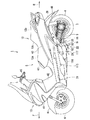
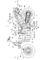
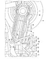
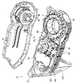
本発明の実施形態に係るセンタースタンド構造が適用される電動二輪車の左側面図。1 is a left side view of an electric motorcycle to which a center stand structure according to an embodiment of the present invention is applied. 本発明の実施形態に係るセンタースタンド構造が適用される電動二輪車の外装等を外した状態を示す左側面図。The left view which shows the state which removed the exterior etc. of the electric motorcycle to which the center stand structure which concerns on embodiment of this invention is applied. 本発明の実施形態に係るセンタースタンド構造が適用される電動二輪車の外装等を外した状態を示す斜視図。The perspective view which shows the state which removed the exterior etc. of the electric motorcycle to which the center stand structure which concerns on embodiment of this invention is applied. 本発明の実施形態に係る電動二輪車のセンタースタンド構造の左側面図。The left view of the center stand structure of the electric motorcycle which concerns on embodiment of this invention. 本発明の実施形態に係る電動二輪車のセンタースタンド構造の底面図。The bottom view of the center stand structure of the electric motorcycle which concerns on embodiment of this invention. 本発明の実施形態に係る電動二輪車のスイングアームの分解斜視図。1 is an exploded perspective view of a swing arm of an electric motorcycle according to an embodiment of the present invention. 本発明の実施形態に係る電動二輪車のスイングアームの側面図。1 is a side view of a swing arm of an electric motorcycle according to an embodiment of the present invention. 本発明の実施形態に係る電動二輪車のセンタースタンドの斜視図。1 is a perspective view of a center stand of an electric motorcycle according to an embodiment of the present invention. 本発明の実施形態に係る電動二輪車のセンタースタンドの底面図。The bottom view of the center stand of the electric motorcycle which concerns on embodiment of this invention.

以下、本発明に係る電動二輪車のセンタースタンド構造の実施の形態について、図1から図9を参照して説明する。   Embodiments of a center stand structure for an electric motorcycle according to the present invention will be described below with reference to FIGS.

図1は、本発明の実施形態に係るセンタースタンド構造が適用される電動二輪車の左側面図である。   FIG. 1 is a left side view of an electric motorcycle to which a center stand structure according to an embodiment of the present invention is applied.

図2は、本発明の実施形態に係るセンタースタンド構造が適用される電動二輪車の外装等(カバーやシート)を外した状態を示す左側面図である。   FIG. 2 is a left side view showing a state where an exterior or the like (cover or seat) of the electric motorcycle to which the center stand structure according to the embodiment of the present invention is applied is removed.

図3は、本発明の実施形態に係るセンタースタンド構造が適用される電動二輪車の外装等(カバーやシート)を外した状態を示す斜視図である。   FIG. 3 is a perspective view showing a state in which an exterior or the like (cover or seat) of the electric motorcycle to which the center stand structure according to the embodiment of the present invention is applied is removed.

なお、本実施形態における前後上下左右の表現は、電動二輪車1の搭乗者を基準にする。図1から図3中の実線矢印Fは電動二輪車1の前方を表し、実線矢印Rは電動二輪車1の後方を表している。   In the present embodiment, front / rear, upper / lower / left / right expressions are based on the passenger of the electric motorcycle 1. A solid arrow F in FIGS. 1 to 3 represents the front of the electric motorcycle 1, and a solid arrow R represents the rear of the electric motorcycle 1.

図1から図3に示すように、本実施形態に係る電動二輪車1は、燃料電池2で発電し、この電力でモータ3を駆動させて走行する電動車両であり、燃料電池二輪車である。また、電動二輪車1は、スクータ型の二輪車である。   As shown in FIGS. 1 to 3, the electric motorcycle 1 according to the present embodiment is an electric vehicle that travels by generating electricity with the fuel cell 2 and driving the motor 3 with this electric power, and is a fuel cell motorcycle. The electric motorcycle 1 is a scooter type motorcycle.

電動二輪車1は、前後に延びる車体5と、操舵輪としての前輪6と、前輪6を操舵自在に支えるステアリング機構7と、駆動輪としての後輪8と、後輪8を上下方向へ揺動自在に支えるスイングアーム9と、後輪8の駆動力を発生させるモータ3と、を備えている。   The electric motorcycle 1 includes a vehicle body 5 extending in the front-rear direction, a front wheel 6 as a steering wheel, a steering mechanism 7 that supports the front wheel 6 in a steerable manner, a rear wheel 8 as a drive wheel, and a rear wheel 8 that swings up and down. A swing arm 9 that freely supports the motor 3 that generates a driving force for the rear wheel 8 is provided.

車体5は、車両の前後に延びるフレーム11と、フレーム11を覆う外装12と、フレーム11後半部の上方に配置されるシート13と、を備えている。   The vehicle body 5 includes a frame 11 that extends in the front-rear direction of the vehicle, an exterior 12 that covers the frame 11, and a seat 13 that is disposed above the rear half of the frame 11.

また、車体5は、燃料電池2と、燃料電池2で発電に使用される燃料としての水素の高圧ガスを貯蔵する燃料タンク15と、燃料電池2の電力を補助する二次電池16と、燃料電池2の出力電圧の調整と燃料電池2および二次電池16の電力の分配を制御する電力管理装置17と、電力管理装置17が出力する直流電力を三相交流電力に変換してモータ3へ出力し、モータ3を運転するインバータ18と、これらを統括的に管理する車両コントローラ19と、を備えている。   The vehicle body 5 includes a fuel cell 2, a fuel tank 15 that stores high-pressure hydrogen gas as fuel used for power generation in the fuel cell 2, a secondary battery 16 that assists the power of the fuel cell 2, fuel The power management device 17 that controls the adjustment of the output voltage of the battery 2 and the distribution of the power of the fuel cell 2 and the secondary battery 16, and the DC power output from the power management device 17 is converted into three-phase AC power to the motor 3. The inverter 18 which outputs and operates the motor 3 and the vehicle controller 19 which manages these collectively are provided.

電動二輪車1のパワートレインは、燃料電池2および二次電池16を有し、車両の走行状態、燃料電池2の発電状態、二次電池16の蓄電状態によって各電池の電力を適宜に使うシステムである。また、電動二輪車1は、減速する際にモータ3で回生電力を発生させる。車両の電源である二次電池16および燃料電池2は、インバータ18に並列に接続されてモータ3へ電力を供給する。二次電池16は、電動二輪車1が減速する際にモータ3で発生する回生電力および燃料電池2が発電する電力を蓄える。   The power train of the electric motorcycle 1 has a fuel cell 2 and a secondary battery 16, and is a system that appropriately uses the power of each battery depending on the running state of the vehicle, the power generation state of the fuel cell 2, and the storage state of the secondary battery 16. is there. The electric motorcycle 1 generates regenerative electric power with the motor 3 when decelerating. The secondary battery 16 and the fuel cell 2 that are power sources of the vehicle are connected in parallel to the inverter 18 and supply power to the motor 3. The secondary battery 16 stores the regenerative power generated by the motor 3 and the power generated by the fuel cell 2 when the electric motorcycle 1 decelerates.

フレーム11は、複数の鋼鉄製中空管を一体に組み合わせたものである。フレーム11は、前端上部に配置されるヘッドパイプ21と、ヘッドパイプ21の中央部から後ろ下がりに傾斜して延びる上部ダウンフレーム22と、ヘッドパイプ21の下方に配置され、後ろ下がりに傾斜して延びる下部ダウンフレーム23と、左右一対の下部フレーム24と、左右一対の上部フレーム25と、ピボット軸26と、上ブリッジフレーム27と、下ブリッジフレーム28と、ガードフレーム29と、搭載機器保護フレーム30と、を備えている。   The frame 11 is a combination of a plurality of hollow steel tubes. The frame 11 includes a head pipe 21 disposed at the upper front end, an upper down frame 22 that extends from the center of the head pipe 21 so as to incline backward, and is disposed below the head pipe 21 and inclines rearwardly downward. An extended lower down frame 23, a pair of left and right lower frames 24, a pair of left and right upper frames 25, a pivot shaft 26, an upper bridge frame 27, a lower bridge frame 28, a guard frame 29, and a mounted device protection frame 30 And.

ヘッドパイプ21は、ステアリング機構7を操舵自在、つまり車両の左右方向へ揺動自在に支持している。   The head pipe 21 supports the steering mechanism 7 so as to be steerable, that is, swingable in the left-right direction of the vehicle.

左右一対の下部フレーム24は、下部ダウンフレーム23の左右に配置され、ヘッドパイプ21の下部に接続されている。また、左右一対の下部フレーム24は、ヘッドパイプ21との接続部分から下部ダウンフレーム23に沿って略平行に、かつ後ろ下がりに傾斜して延びる前側傾斜部分と、傾斜部分の下端で後方に向かって湾曲する前側の湾曲部分と、前側の湾曲部分の後端から略水平に車体5の後方へ向かって車体5の中央部分(車両の前後方向で中央部分)に達するまで直線状に延びる直線部分と、を有している。さらに、左右一対の下部フレーム24は、直線部分の後端部から後上方に向けて湾曲する後ろ側の湾曲部分と、この後ろ側の湾曲部分の上端部から後ろ上がりに傾斜して延びる後側傾斜部分を経て上部フレーム25に接続される上下フレーム接合部と、を有している。なお、左右の下部フレーム24の間隔は、上部フレーム25の間隔よりも広い。   The pair of left and right lower frames 24 are arranged on the left and right of the lower down frame 23 and connected to the lower portion of the head pipe 21. The pair of left and right lower frames 24 extend from the connecting portion to the head pipe 21 toward the rear at the front inclined portion that extends substantially in parallel along the lower down frame 23 and tilts backward and downward, and at the lower end of the inclined portion. And a straight portion extending linearly from the rear end of the front curved portion toward the rear of the vehicle body 5 until reaching the central portion of the vehicle body 5 (the central portion in the vehicle front-rear direction). And have. Furthermore, the pair of left and right lower frames 24 includes a rear curved portion that curves from the rear end of the straight portion toward the rear upper side, and a rear side that extends obliquely upward from the upper end of the rear curved portion. And an upper and lower frame joint portion connected to the upper frame 25 through an inclined portion. Note that the interval between the left and right lower frames 24 is wider than the interval between the upper frames 25.

また、左右それぞれの下部フレーム24は、前側の湾曲部分の外側に搭乗者が足を置くフットボード31を下方から支持するフットレストブラケット31aを備えている。   Each of the left and right lower frames 24 includes a footrest bracket 31a that supports a footboard 31 on which a rider puts his / her foot from below the front curved portion.

車体5の左側に配置される下部フレーム24は、サイドスタンドブラケット(図示省略)を備えている。サイドスタンドブラケット(図示省略)には、電動二輪車1を左側へ傾けた状態で自立させるサイドスタンド(図示省略)が設けられている。サイドスタンド32は、電動二輪車1を自立させる起立状態と、走行の妨げとならないよう車体5に添う収納状態との間を揺動する。   The lower frame 24 disposed on the left side of the vehicle body 5 includes a side stand bracket (not shown). The side stand bracket (not shown) is provided with a side stand (not shown) that allows the electric motorcycle 1 to stand by itself while being tilted to the left. The side stand 32 swings between an upright state in which the electric motorcycle 1 is self-supporting and a stored state that follows the vehicle body 5 so as not to hinder travel.

左右一対の上部フレーム25は、車体5の前半部において下部フレーム24の前側の傾斜部分の上下方向の中央部に接続されている。左右一対の上部フレーム25は、下部フレーム24の前側の傾斜部分との接続部分から車体5の後方に向かって略水平に延びる水平部分と、左右一対の上部フレーム25の水平部分の後端であって、車体5の後半部、かつ後輪8の上方部分において後ろ上がりに大きく傾斜し、車体5の左右方向内側へ湾曲して後輪8の太さ(幅寸法)程度に接近する後端部と、を有している。   The pair of left and right upper frames 25 are connected to the center in the vertical direction of the inclined portion on the front side of the lower frame 24 in the front half of the vehicle body 5. The pair of left and right upper frames 25 are a horizontal portion extending substantially horizontally from the connection portion with the front inclined portion of the lower frame 24 toward the rear of the vehicle body 5 and a rear end of the horizontal portion of the pair of left and right upper frames 25. The rear end of the rear half of the vehicle body 5 and the upper end of the rear wheel 8 greatly inclines rearward and curves inward in the left-right direction of the vehicle body 5 and approaches the thickness (width dimension) of the rear wheel 8. And have.

ピボット軸26は、車体5の後半部において左右の上部フレーム25間に架設されている。また、ピボット軸26は、上部フレーム25の下側、かつ上部フレーム25と下部フレーム24との合流部分(上下フレーム接合部)よりも後方であって、上部フレーム25の水平部分と下部フレーム24の後側傾斜部分とに接続されるブラケット26aに配置されている。   The pivot shaft 26 is installed between the left and right upper frames 25 in the rear half of the vehicle body 5. The pivot shaft 26 is located below the upper frame 25 and behind the junction (upper and lower frame joints) between the upper frame 25 and the lower frame 24, and between the horizontal portion of the upper frame 25 and the lower frame 24. It arrange | positions at the bracket 26a connected to a back side inclination part.

上ブリッジフレーム27は、左右の上部フレーム25の前端部に架設されている。上ブリッジフレーム27は、左右の上部フレーム25の間を実質的に車両の左右方向へ直線状に延びて、左右の上部フレーム25を連結している。   The upper bridge frame 27 is constructed at the front end portions of the left and right upper frames 25. The upper bridge frame 27 extends substantially linearly between the left and right upper frames 25 in the left-right direction of the vehicle, and connects the left and right upper frames 25.

下ブリッジフレーム28は、左右の下部フレーム24の前側の屈曲部分に架設されている。下ブリッジフレーム28は、左右の下部フレーム24の間を実質的に車両の左右方向へ直線状に延びて、左右の下部フレーム24を連結している。   The lower bridge frame 28 is installed on a bent portion on the front side of the left and right lower frames 24. The lower bridge frame 28 extends between the left and right lower frames 24 substantially in a straight line in the left-right direction of the vehicle, and connects the left and right lower frames 24.

ガードフレーム29は、左右の下部フレーム24の後側の湾曲部分に架設されている。ガードフレーム29は、左右の下部フレーム24との接続部分から後下方に延びるとともに、フレーム11の内部空間を拡大するように後ろ下がりのU字形状に延びている。ガードフレーム29には、電動二輪車1を直立状態で自立させるセンタースタンド33が設けられている。センタースタンド33は、電動二輪車1を自立させる起立状態と、走行の妨げとならないよう車体5に添う収納状態との間を揺動する。   The guard frame 29 is installed on the curved portion on the rear side of the left and right lower frames 24. The guard frame 29 extends rearward and downward from the connection portion with the left and right lower frames 24 and extends in a U-shape that is rearwardly lowered so as to enlarge the internal space of the frame 11. The guard frame 29 is provided with a center stand 33 that allows the electric motorcycle 1 to stand upright in an upright state. The center stand 33 swings between an upright state in which the electric motorcycle 1 is self-supporting and a stored state along the vehicle body 5 so as not to hinder travel.

上部ダウンフレーム22は、ヘッドパイプ21と上ブリッジフレーム27との間に架設されている。   The upper down frame 22 is constructed between the head pipe 21 and the upper bridge frame 27.

下部ダウンフレーム23は、左右の下部フレーム24の上部の間で実質的に車両の左右方向へ直線状に延びて架設されるヘッドパイプ近傍ブリッジフレーム34の車両の左右方向中央部に接続される上端部と、下ブリッジフレーム28の車両の左右方向中央部に接続される下端部とを有している。   The lower down frame 23 is an upper end connected to the center portion in the left and right direction of the vehicle of the head pipe vicinity bridge frame 34 which extends between the upper portions of the left and right lower frames 24 and extends substantially linearly in the left and right direction of the vehicle. And a lower end portion of the lower bridge frame 28 connected to the central portion in the left-right direction of the vehicle.

搭載機器保護フレーム30は、上部フレーム25の後半部の上部に設けられている。搭載機器保護フレーム30は、燃料電池2を電動二輪車1の車体に支持している。また、搭載機器保護フレーム30は、その一部を上部フレーム25に着脱できる。   The mounted device protection frame 30 is provided on the upper part of the rear half of the upper frame 25. The on-board equipment protection frame 30 supports the fuel cell 2 on the vehicle body of the electric motorcycle 1. A part of the on-board device protection frame 30 can be attached to and detached from the upper frame 25.

シート13は、フレーム11の後半部上方を覆って前後に延びている。シート13はタンデム式であり、搭乗者を着座させる前半部13aと、同乗者を着座させる後半部13bとを一体的に備えている。また、シート13は、前半部13aと後半部13bとの間に傾斜部13cを備えている。   The seat 13 extends back and forth so as to cover the upper part of the rear half of the frame 11. The seat 13 is a tandem type and integrally includes a front half 13a for seating a passenger and a rear half 13b for seating the passenger. Further, the seat 13 includes an inclined portion 13c between the front half portion 13a and the rear half portion 13b.

ここで、左右の上部フレーム25および左右の下部フレーム24で囲まれる空間をセンタートンネル領域35と呼び、上部フレーム25の後半部、外装12およびシート13で囲まれる空間を機器搭載領域36と呼び、センタートンネル領域35の後方かつ機器搭載領域36の下方の空間をタイヤハウス領域37と呼ぶ。   Here, a space surrounded by the left and right upper frames 25 and the left and right lower frames 24 is referred to as a center tunnel region 35, and a space surrounded by the latter half of the upper frame 25, the exterior 12 and the seat 13 is referred to as a device mounting region 36, A space behind the center tunnel region 35 and below the device mounting region 36 is referred to as a tire house region 37.

センタートンネル領域35は、燃料タンク15を収容している。本実施形態に係るスクータ型の電動二輪車1では、センタートンネル領域35は、搭乗者が足を乗せる左右のフットボード31の間で、車両の前後方向に沿って配置され、フットボード31の足載せ領域を左右に分断するようにフットボード31から上方に隆起している。換言すると、センタートンネル領域35の左右には、足載せ領域となるフットボードが配置され、左右のフットボード31の間に燃料タンク15が配置されている。   The center tunnel region 35 accommodates the fuel tank 15. In the scooter type electric motorcycle 1 according to the present embodiment, the center tunnel region 35 is disposed along the front-rear direction of the vehicle between the left and right footboards 31 on which the rider puts his / her foot. It bulges upward from the footboard 31 so as to divide the region into left and right. In other words, footboards serving as footrest areas are arranged on the left and right sides of the center tunnel area 35, and the fuel tank 15 is arranged between the left and right footboards 31.

機器搭載領域36は、車体5の前側から順に二次電池16、電力管理装置17、燃料電池2を収容している。機器搭載領域36は、搭載機器保護フレーム30によって前端部、中央部、後端部、および中央部から後端部に渡る側部を保護されている。   The device mounting area 36 accommodates the secondary battery 16, the power management device 17, and the fuel cell 2 in order from the front side of the vehicle body 5. The device mounting area 36 is protected by the mounted device protection frame 30 at the front end, the center, the rear end, and the side from the center to the rear end.

搭載機器保護フレーム30は、機器搭載領域36を囲んで機器搭載領域36に搭載される機器を保護している。搭載機器保護フレーム30は、機器搭載領域36の前端部に配置されて左右の上部フレーム25の間で上に凸のアーチ状に架設される前保護フレーム30aと、機器搭載領域36の中央部であって、上部フレーム25と下部フレーム24との合流箇所よりも後ろ側に配置されて左右の上部フレーム25の間で上に凸のアーチ状に架設される中央保護フレーム30bと、機器搭載領域36の後端部に配置されて左右それぞれの上部フレーム25が内側に湾曲する部分に接続され、この湾曲部分から後ろ斜め上方へ延びる左右一対の後保護フレーム30cと、中央保護フレーム30bの左右それぞれから後方へ延びて後保護フレーム30cの上端部に接続され、さらに車体5の後端部へ到達する左右一対の側部保護フレーム30dと、左右の側部保護フレーム30dの後端部に架設されるブラケット30eと、を備えている。左右の上部フレーム25は、前保護フレーム30aの下端が接合される箇所で屈曲して車両の後方に向かって間隔を拡げ、中央保護フレーム30bの下端が接合される箇所で屈曲して車両の後方に延びている。このため、中央保護フレーム30bは、前保護フレーム30aよりも幅が広く、高さも高い。後保護フレーム30cおよび左右一対の側部保護フレーム30dは一体化されている。また、後保護フレーム30cおよび左右一対の側部保護フレーム30dは、中央保護フレーム30bおよび上部フレーム25に着脱自在に連結されて燃料電池2を支持している。   The mounted device protection frame 30 surrounds the device mounting area 36 and protects the devices mounted in the device mounting area 36. The mounted device protection frame 30 is disposed at the front end portion of the device mounting region 36 and is disposed at the center portion of the device mounting region 36 and the front protective frame 30a that is erected upwardly between the left and right upper frames 25 in an upwardly projecting arch shape. A central protective frame 30b disposed behind the junction of the upper frame 25 and the lower frame 24 and erected upward in a convex arch shape between the left and right upper frames 25; The left and right upper frames 25 are connected to a portion that is curved inwardly and is disposed at the rear end portion, and a pair of left and right rear protective frames 30c extending obliquely rearward and upward from the curved portion, and left and right of the central protective frame 30b. A pair of left and right side protection frames 30d extending rearward and connected to the upper end of the rear protection frame 30c and reaching the rear end of the vehicle body 5, and left and right side parts A bracket 30e that spans between the rear edges of the protection frame 30d, and a. The left and right upper frames 25 are bent at a portion where the lower end of the front protective frame 30a is joined to increase the distance toward the rear of the vehicle, and are bent at a portion where the lower end of the central protective frame 30b is joined. It extends to. For this reason, the center protection frame 30b is wider and higher in height than the front protection frame 30a. The rear protection frame 30c and the pair of left and right side protection frames 30d are integrated. The rear protection frame 30c and the pair of left and right side protection frames 30d are detachably connected to the central protection frame 30b and the upper frame 25 to support the fuel cell 2.

タイヤハウス領域37には後輪8が配置されている。   A rear wheel 8 is disposed in the tire house region 37.

機器搭載領域36とタイヤハウス領域37との間には、それぞれの領域を分断する隔壁部材としてのリアフェンダ38が設けられている。   Between the equipment mounting area 36 and the tire house area 37, a rear fender 38 is provided as a partition member that divides each area.

外装12は、車体5の前半部を覆うフロントレッグシールドカバー41と、車体5の中央上部に配置されてセンタートンネル領域35などの上部フレーム25の上方を覆うフロントフレームカバー42と、車体5の後半部に配置されて機器搭載領域36などの車体5の側面のうちシート13の下方部分を覆うフレームカバー43と、を備えている。   The exterior 12 includes a front leg shield cover 41 that covers the front half of the vehicle body 5, a front frame cover 42 that is disposed at the upper center of the vehicle body 5 and covers the upper frame 25 such as the center tunnel region 35, and the rear half of the vehicle body 5. And a frame cover 43 that covers the lower portion of the seat 13 among the side surfaces of the vehicle body 5 such as the device mounting area 36.

フレームカバー43は、シート13とともに機器搭載領域36を囲んでいる。機器搭載領域36は、シート13、フレームカバー43およびリアフェンダ38に囲まれる閉鎖的な空間である。機器搭載領域36は、フレームカバー43、もしくはリアフェンダ38の適宜の箇所に設けられる通気孔(図示省略)によって、燃料電池2への空気の流れを容易、かつ確実に制御し、また冷却が必要な装置へ冷却風としての空気の流れを容易、かつ確実に制御している。なお、機器搭載領域36は、各カバーの継ぎ目などから空気が入り込むことを許容する。   The frame cover 43 surrounds the device mounting area 36 together with the seat 13. The device mounting area 36 is a closed space surrounded by the seat 13, the frame cover 43, and the rear fender 38. In the device mounting area 36, air flow to the fuel cell 2 is easily and reliably controlled by a vent hole (not shown) provided at an appropriate position of the frame cover 43 or the rear fender 38, and cooling is necessary. The flow of air as cooling air to the device is controlled easily and reliably. The device mounting area 36 allows air to enter from the joints of the covers.

ステアリング機構7は、車体5の前方に配置されて、フレーム11のヘッドパイプ21を中心に左右方向へ揺動し前輪6の操舵を可能にする。ステアリング機構7は、頂部に設けられるハンドル45と、ハンドル45と前輪6とを連結し、若干後傾して上下に延びる左右一対のフロントフォーク46と、を備えている。左右のフロントフォーク46は、弾性的に伸縮自在なテレスコピック構造を備えている。左右のフロントフォーク46の下端部には、前輪6を回転自在に支持する車軸(図示省略)が架設されている。前輪6の上方には、フロントフェンダ47が配置されている。フロントフェンダ47は、左右のフロントフォーク46の間にあって、フロントフォーク46に固定されている。   The steering mechanism 7 is disposed in front of the vehicle body 5 and swings in the left-right direction around the head pipe 21 of the frame 11 to enable steering of the front wheels 6. The steering mechanism 7 includes a handle 45 provided at the top, and a pair of left and right front forks 46 that connect the handle 45 and the front wheel 6 and extend slightly upward and downward. The left and right front forks 46 have a telescopic structure that is elastically expandable. An axle (not shown) that rotatably supports the front wheel 6 is installed at the lower ends of the left and right front forks 46. A front fender 47 is disposed above the front wheel 6. The front fender 47 is between the left and right front forks 46 and is fixed to the front fork 46.

前輪6は、左右のフロントフォーク46の下端部に架設されている車軸の周りに回転自在な従動輪である。   The front wheel 6 is a driven wheel that is rotatable around an axle that is installed at the lower ends of the left and right front forks 46.

スイングアーム9は、車体5の左右へ延びている回転中心としてのピボット軸26の周りに上下方向へ揺動する。スイングアーム9は、車体5の左右で前後方向に延びる一対のアーム部の間に後輪8を回転自在に支持している。フレーム11とスイングアーム9との間には、リアサスペンション48が架設されている。リアサスペンション48の上端部は、上部フレーム25の後端部に揺動自在に支持されている。リアサスペンション48の下端部は、スイングアーム9の後端部に揺動自在に取り付けられている。リアサスペンション48は、スイングアーム9の揺動を緩衝する。   The swing arm 9 swings up and down around a pivot shaft 26 serving as a rotation center extending to the left and right of the vehicle body 5. The swing arm 9 rotatably supports the rear wheel 8 between a pair of arm portions extending in the front-rear direction on the left and right sides of the vehicle body 5. A rear suspension 48 is installed between the frame 11 and the swing arm 9. The upper end portion of the rear suspension 48 is swingably supported by the rear end portion of the upper frame 25. The lower end of the rear suspension 48 is swingably attached to the rear end of the swing arm 9. The rear suspension 48 buffers swinging of the swing arm 9.

またスイングアーム9は、後輪8を回転駆動させるモータ3と、燃料電池2から供給される直流電力を交流電力に変換してモータ3へ供給するインバータ18と、を収容している。   The swing arm 9 houses a motor 3 that rotates the rear wheel 8 and an inverter 18 that converts DC power supplied from the fuel cell 2 into AC power and supplies the AC power to the motor 3.

モータ3は、燃料電池2または二次電池16から供給される電力によって後輪8を回転駆動させる。モータ3は、スイングアーム9の後部に収容されて、後輪8の車軸と同軸に配置されている。モータ3はスイングアーム9に一体的に組み付けられてユニットスイング式スイングアームを構成している。   The motor 3 rotates the rear wheel 8 with electric power supplied from the fuel cell 2 or the secondary battery 16. The motor 3 is accommodated in the rear part of the swing arm 9 and is arranged coaxially with the axle of the rear wheel 8. The motor 3 is integrally assembled with the swing arm 9 to constitute a unit swing type swing arm.

インバータ18は、スイングアーム9の前部に収容されて、ピボット軸26とモータ3との間に配置されている。   The inverter 18 is accommodated in the front portion of the swing arm 9 and is disposed between the pivot shaft 26 and the motor 3.

後輪8は、モータ3から駆動力が伝達される車軸(図示省略)によって支えられる駆動輪である。   The rear wheel 8 is a driving wheel supported by an axle (not shown) to which driving force is transmitted from the motor 3.

燃料電池2は、燃料と酸化剤とを反応させて発電する。燃料電池2は、燃料として高圧ガス、例えば水素ガスを使用し、酸化剤として空気中の酸素を使用して発電し、空気を用いて冷却する空冷式燃料電池システムである。   The fuel cell 2 generates electricity by reacting a fuel and an oxidant. The fuel cell 2 is an air-cooled fuel cell system that uses a high pressure gas, for example, hydrogen gas, as a fuel, generates oxygen using oxygen in the air as an oxidant, and cools it using air.

燃料電池2は、機器搭載領域36の後半側に配置されている。さらに具体的には、燃料電池2は、シート13の前半部13aと後半部13bとの間の傾斜部から後半部13bの下方に渡って配置されている。つまり、車両の側面視で、燃料電池2は、同乗者を着座させるシート13の後半部13bと後輪8やスイングアーム9との間に配置されている。   The fuel cell 2 is disposed on the second half side of the device mounting area 36. More specifically, the fuel cell 2 is disposed from the inclined portion between the front half portion 13a and the rear half portion 13b of the seat 13 and below the rear half portion 13b. That is, as viewed from the side of the vehicle, the fuel cell 2 is disposed between the rear half portion 13 b of the seat 13 on which the passenger is seated, the rear wheel 8 and the swing arm 9.

燃料電池2は、車体5の前後方向に延びる長辺を有する直方体形状であって、吸気口2aが配置される正面を前斜め下方へ向け、排気口2bが配置される背面を後ろ斜め上方へ向ける姿勢で機器搭載領域36に配置されている。つまり、燃料電池2は、前方側が後方側よりも下方に位置する前傾姿勢でフレーム11に固定されている。詳細には、燃料電池2の上部は搭載機器保護フレーム30に固定され、燃料電池2の下部は上部フレーム25に固定されている。   The fuel cell 2 has a rectangular parallelepiped shape having a long side extending in the front-rear direction of the vehicle body 5. The front surface on which the intake port 2 a is disposed is directed obliquely downward in the front direction, and the rear surface on which the exhaust port 2 b is disposed is disposed obliquely upward on the rear side. It arrange | positions in the apparatus mounting area | region 36 with the attitude | position which faces. That is, the fuel cell 2 is fixed to the frame 11 in a forward tilt posture in which the front side is positioned below the rear side. Specifically, the upper part of the fuel cell 2 is fixed to the mounted device protection frame 30, and the lower part of the fuel cell 2 is fixed to the upper frame 25.

燃料電池2は、正面側から背面側へ向かって連結される扁平な複数のモジュールを含んでいる。具体的には、燃料電池2は、正面側から順に積層状態に重ねられて連結されるフィルタ(図示省略)、吸気シャッタ(図示省略)、燃料電池スタック(図示省略)、ファン(図示省略)、排気シャッタ(図示省略)を有している。燃料電池2の天面には、燃料電池用制御部(図示省略)が設けられている。   The fuel cell 2 includes a plurality of flat modules connected from the front side to the back side. Specifically, the fuel cell 2 includes a filter (not shown), an intake shutter (not shown), a fuel cell stack (not shown), a fan (not shown), connected in a stacked state in order from the front side, An exhaust shutter (not shown) is provided. A fuel cell control unit (not shown) is provided on the top surface of the fuel cell 2.

吸気シャッタは、開閉自在な空気の吸気口2aを有し、吸気口2aを開閉して燃料電池スタックへの空気の導入量を制御することができるとともに、吸気口2aを閉じて燃料電池2内で空気を循環させる循環経路を形成することができる。排気シャッタは、開閉自在な空気の排気口2bを有し、排気口2bを閉じて燃料電池2内で空気を循環させる循環経路を形成することができる。換言すると、燃料電池2は、正面に開閉可能な吸気口2aを有し、背面に開閉可能な排気口2bを有し、吸気口2aと排気口2bを閉じることで燃料電池2内の空気を循環させることができる。   The intake shutter has an air intake port 2a that can be freely opened and closed, and can control the amount of air introduced into the fuel cell stack by opening and closing the air intake port 2a. A circulation path for circulating air can be formed. The exhaust shutter has an air exhaust port 2 b that can be freely opened and closed, and can form a circulation path that circulates air in the fuel cell 2 by closing the exhaust port 2 b. In other words, the fuel cell 2 has an intake port 2a that can be opened and closed on the front side, an exhaust port 2b that can be opened and closed on the back side, and closes the intake port 2a and the exhaust port 2b to remove the air in the fuel cell 2 It can be circulated.

燃料電池スタックは、吸気口から吸い込まれる空気に含まれる酸素と燃料タンク15から供給される水素とを電気化学反応させて発電し、発電後に湿潤な余剰ガスを生成する。   The fuel cell stack generates electricity by causing an electrochemical reaction between oxygen contained in the air sucked from the air inlet and hydrogen supplied from the fuel tank 15, and generates wet surplus gas after power generation.

ファンは、機器搭載領域36内の空気を吸気口から燃料電池2内に吸い込むための吸込負圧を発生させる一方で、燃料電池スタックから余剰ガスを吸い出して排気口から排気する。ファンが流動させる空気の流れは、燃料電池スタックで発電に用いられる他に、燃料電池2の冷却に利用される。   The fan generates suction negative pressure for sucking air in the device mounting area 36 into the fuel cell 2 from the intake port, while sucking excess gas from the fuel cell stack and exhausting it from the exhaust port. In addition to being used for power generation in the fuel cell stack, the air flow caused by the fan is used for cooling the fuel cell 2.

燃料電池2の後方には、排気ダクト52が設けられている。燃料電池2のファンは、余剰ガスを燃料電池スタックから吸い出して排気ダクト52へ排気する。排気ダクト52の前端部は、燃料電池2の箱体(詳細には、排気シャッタの枠体)に気密に接続されている。排気ダクト52は、車体5の後端で後下方と後上方に向かって開口される排気口52aを有している。排気ダクト52は、燃料電池2のファンから吐出される排気(余剰ガス)を、排気口52aへ導いて車体5の後方へ排出する。   An exhaust duct 52 is provided behind the fuel cell 2. The fan of the fuel cell 2 sucks excess gas from the fuel cell stack and exhausts it to the exhaust duct 52. The front end of the exhaust duct 52 is airtightly connected to the box of the fuel cell 2 (specifically, the frame of the exhaust shutter). The exhaust duct 52 has an exhaust port 52a that opens toward the rear lower side and the rear upper side at the rear end of the vehicle body 5. The exhaust duct 52 guides exhaust (surplus gas) discharged from the fan of the fuel cell 2 to the exhaust port 52 a and exhausts it to the rear of the vehicle body 5.

排気ダクト52の排気口52aは、燃料電池2の排気面(背面)よりも上方であって、望ましくは排気ダクト52の後方上端部に配置されている。詳細には、燃料電池2の排気口よりも高い位置に排気口52aの上縁部が配置されている。排気ダクト52は、燃料電池2の排気面(背面)よりも上方に配置される排気口52aを有することによって、未反応の水素ガスを含む湿潤な余剰ガスを排気口52aに導いて車体5から確実に排気することができる。   The exhaust port 52 a of the exhaust duct 52 is located above the exhaust surface (back surface) of the fuel cell 2, and is preferably disposed at the upper rear end of the exhaust duct 52. Specifically, the upper edge portion of the exhaust port 52 a is disposed at a position higher than the exhaust port of the fuel cell 2. The exhaust duct 52 has an exhaust port 52 a disposed above the exhaust surface (back surface) of the fuel cell 2, thereby leading wet excess gas containing unreacted hydrogen gas to the exhaust port 52 a from the vehicle body 5. It is possible to exhaust reliably.

燃料タンク15は高圧圧縮水素貯蔵システムである。燃料タンク15は、炭素繊維強化プラスチック(CFRP)製の、あるいはアルミライナ製複合容器である圧力容器55と、燃料充填口56を有する燃料充填用継手57と、燃料充填元弁58と、遮断弁(図示省略)とレギュレータ(図示省略)とを一体的に有する燃料供給元弁59と、を備えている。   The fuel tank 15 is a high-pressure compressed hydrogen storage system. The fuel tank 15 includes a pressure vessel 55 which is a composite vessel made of carbon fiber reinforced plastic (CFRP) or an aluminum liner, a fuel filling joint 57 having a fuel filling port 56, a fuel filling source valve 58, a shut-off valve. A fuel supply source valve 59 integrally including a regulator (not shown) and a regulator (not shown).

圧力容器55は、燃料電池2の燃料としての水素ガスを貯蔵するアルミライナ製複合容器である。燃料タンク15は、例えば約70MPaの水素ガスを貯蔵する。圧力容器55は、円筒形状の胴部と、胴部の前後の端面にドーム状の鏡板と、を有している。圧力容器55は、円筒胴の中心線を車体5の前後方向へ沿わせてセンタートンネル領域35内に配置されている。圧力容器55は、一対の上部フレーム25、一対の下部フレーム24、下ブリッジフレーム28、およびガードフレーム29に周囲を囲まれて、電動二輪車1の転倒や衝突による負荷に対して堅牢に保護されている。   The pressure vessel 55 is an aluminum liner composite vessel that stores hydrogen gas as fuel for the fuel cell 2. The fuel tank 15 stores, for example, about 70 MPa of hydrogen gas. The pressure vessel 55 has a cylindrical body and dome-shaped end plates on front and rear end surfaces of the body. The pressure vessel 55 is disposed in the center tunnel region 35 with the center line of the cylindrical body along the front-rear direction of the vehicle body 5. The pressure vessel 55 is surrounded by the pair of upper frames 25, the pair of lower frames 24, the lower bridge frame 28, and the guard frame 29, and is firmly protected against a load caused by the electric motorcycle 1 falling or colliding. Yes.

また、圧力容器55は、車体5の一方側の側部に配置される上部フレーム25、例えば車体5の右側に配置される上部フレーム25と、車体5の他方側の側部に配置される下部フレーム24、例えば車体5の左側に配置される下部フレーム24との間に架設されるクランプバンド61によってセンタートンネル領域35に支持されている。詳細には、圧力容器55は、右側の上部フレーム25と左側の下部フレーム24との間に架設される下クランプバンド(クランプバンド61の下半部)に載置され、上クランプバンド(クランプバンド61の上半部)で締め付け挟持されている。なお、クランプバンド61は、車体5の左側に配置される上部フレーム25と、車体5の右側に配置される下部フレーム24との間に架設されていても良い。   The pressure vessel 55 includes an upper frame 25 disposed on one side portion of the vehicle body 5, for example, an upper frame 25 disposed on the right side of the vehicle body 5, and a lower portion disposed on the other side portion of the vehicle body 5. The center tunnel region 35 supports the frame 24, for example, a clamp band 61 installed between the lower frame 24 disposed on the left side of the vehicle body 5. More specifically, the pressure vessel 55 is placed on a lower clamp band (lower half of the clamp band 61) installed between the right upper frame 25 and the left lower frame 24, and an upper clamp band (clamp band). The upper half of 61 is clamped and clamped. The clamp band 61 may be provided between the upper frame 25 disposed on the left side of the vehicle body 5 and the lower frame 24 disposed on the right side of the vehicle body 5.

燃料充填用継手57は、センタートンネル領域35の外側、詳しくは後ろ上方であって、機器搭載領域36の前端部に配置されている。燃料充填用継手57は、二次電池16よりも上方、あるいは真上に配置されている。燃料充填用継手57は、搭載機器保護フレーム30の前保護フレーム30aの上部と中央保護フレーム30bの上部との間に架設される継手用ブラケット30fに固定されている。燃料充填用継手57は、燃料充填時に設備側の継手を車体の上方、かつ左側から差し込めるよう、車体5の上方、かつやや左側に向かって延びている。燃料充填用継手57は、シート13の前端部に設けられる燃料充填口用リッド62によって覆い隠されている。燃料充填口用リッド62は、ヒンジ機構(図示省略)を介してシート13に支持されており、揺動することで開閉できる。燃料充填用継手57は、燃料としての水素の高圧ガスを燃料タンク15に導き入れる入口としての燃料充填口56を有している。   The fuel filling joint 57 is disposed on the outside of the center tunnel region 35, specifically on the rear upper side, and on the front end portion of the device mounting region 36. The fuel filling joint 57 is disposed above or directly above the secondary battery 16. The fuel filling joint 57 is fixed to a joint bracket 30f provided between the upper part of the front protection frame 30a of the mounted equipment protection frame 30 and the upper part of the central protection frame 30b. The fuel filling joint 57 extends toward the upper side of the vehicle body 5 and slightly to the left so that the joint on the facility side can be inserted from the upper side and the left side of the vehicle body during fuel filling. The fuel filling joint 57 is covered with a fuel filling port lid 62 provided at the front end of the seat 13. The fuel filling lid 62 is supported on the seat 13 via a hinge mechanism (not shown) and can be opened and closed by swinging. The fuel filling joint 57 has a fuel filling port 56 as an inlet for introducing hydrogen high-pressure gas as fuel into the fuel tank 15.

燃料充填口56は、燃料充填用継手57の頂部に配置されている。また、燃料充填口56は、車体5の左上方を向いている。燃料タンク15に燃料を充填する際、燃料充填口用リッド62を開放した状態において、燃料充填口56の上方は、雰囲気に開放されている。したがって、高圧ガス(燃料、水素ガス)を燃料タンク15に充填する際、仮に高圧ガス(燃料、水素ガス)が漏洩しても、漏洩燃料は滞留することなく電動二輪車1の上方へ拡散する。   The fuel filling port 56 is disposed at the top of the fuel filling joint 57. Further, the fuel filling port 56 faces the upper left of the vehicle body 5. When the fuel tank 15 is filled with fuel, the upper portion of the fuel filling port 56 is open to the atmosphere in a state where the fuel filling port lid 62 is opened. Therefore, when the high pressure gas (fuel, hydrogen gas) is filled in the fuel tank 15, even if the high pressure gas (fuel, hydrogen gas) leaks, the leaked fuel diffuses upward of the electric motorcycle 1 without staying.

燃料充填元弁58および燃料供給元弁59は、一体化されて圧力容器55の後方側の鏡板の頂部に設けられているタンクバルブ63に内蔵されている。燃料供給元弁59の遮断弁は、電磁弁を用いた開閉弁である。タンクバルブ63は、ガードフレーム29で囲まれた空間に配置されている。   The fuel filling source valve 58 and the fuel supply source valve 59 are integrated into a tank valve 63 provided at the top of the end plate on the rear side of the pressure vessel 55. The shutoff valve of the fuel supply source valve 59 is an open / close valve using an electromagnetic valve. The tank valve 63 is disposed in a space surrounded by the guard frame 29.

二次電池16は、箱状のリチウムイオン電池である。二次電池16は、機器搭載領域36の前端部であって、圧力容器55の後半部、つまり円筒胴の後半部、および後方側の鏡板とシート13の前半部13aとの間に配置されている。   The secondary battery 16 is a box-shaped lithium ion battery. The secondary battery 16 is disposed at the front end of the device mounting area 36 and between the rear half of the pressure vessel 55, that is, the rear half of the cylindrical body, and the rear end plate and the front half 13a of the seat 13. Yes.

なお、電動二輪車1は、二次電池16の他に、メータ類(図示省略)、ランプ類(図示省略)用の電源として、例えば12V系の電力を供給する第2二次電池(図示省略)を備えている。第2二次電池は、ヘッドパイプ21の周囲、例えば、ヘッドパイプ21の右側の側方に配置されている。   The electric motorcycle 1 includes a secondary battery (not shown) that supplies, for example, 12V power as a power source for meters (not shown) and lamps (not shown) in addition to the secondary battery 16. It has. The second secondary battery is arranged around the head pipe 21, for example, on the right side of the head pipe 21.

また、仮に燃料充填口56から燃料としての水素ガスが漏洩しても、空気より軽い水素ガスは上昇して、車内に滞留することなく車外に拡散する。また、仮に燃料充填元弁58または燃料供給元弁59から燃料としての水素ガスが漏洩しても、水素ガスはタイヤハウス領域37に向かって移動して、車内に滞留することなく車外に拡散する。   Even if hydrogen gas as fuel leaks from the fuel filling port 56, the hydrogen gas lighter than air rises and diffuses outside the vehicle without staying in the vehicle. Even if hydrogen gas as fuel leaks from the fuel filling source valve 58 or the fuel supply source valve 59, the hydrogen gas moves toward the tire house region 37 and diffuses outside the vehicle without staying in the vehicle. .

電力管理装置17は、機器搭載領域36内で二次電池16と燃料電池2との間に配置され、フレーム11に固定されている。なお、電力管理装置17は二次電池16と同じ防水ケース内に配置されていても良い。   The power management device 17 is disposed between the secondary battery 16 and the fuel cell 2 in the device mounting area 36 and is fixed to the frame 11. The power management device 17 may be disposed in the same waterproof case as the secondary battery 16.

電動二輪車1は、二次電池16、電力管理装置17、および燃料電池2を上述のように配置することによって、電気的な接続関係が隣り合う装置を極力近接する位置に配置することが可能であり、装置間の配線長を短く、配線に係る重量を軽くすることができる。   In the electric motorcycle 1, the secondary battery 16, the power management device 17, and the fuel cell 2 are arranged as described above, so that devices that are adjacent to each other in electrical connection can be arranged as close as possible. Yes, the wiring length between the devices can be shortened, and the weight related to the wiring can be reduced.

車両コントローラ19は、電動二輪車1内で比較的に高所となるヘッドパイプ21の周囲、例えば、12V系の電力を供給する第2二次電池の反対側にあたるヘッドパイプ21の左側の側方に配置されている。   The vehicle controller 19 is disposed around the head pipe 21 that is relatively high in the electric motorcycle 1, for example, on the left side of the head pipe 21 that is the opposite side of the second secondary battery that supplies 12V power. Has been placed.

次いで、電動二輪車1のセンタースタンド構造69について詳しく説明する。   Next, the center stand structure 69 of the electric motorcycle 1 will be described in detail.

図4は、本発明の実施形態に係る電動二輪車のセンタースタンド構造の左側面図である。   FIG. 4 is a left side view of the center stand structure of the electric motorcycle according to the embodiment of the present invention.

図5は、本発明の実施形態に係る電動二輪車のセンタースタンド構造の底面図である。   FIG. 5 is a bottom view of the center stand structure of the electric motorcycle according to the embodiment of the present invention.

図6は、本発明の実施形態に係る電動二輪車のスイングアームの分解斜視図である。   FIG. 6 is an exploded perspective view of the swing arm of the electric motorcycle according to the embodiment of the present invention.

図7は、本発明の実施形態に係る電動二輪車のスイングアームの側面図である。なお、図7は、カバーの図示が省略されている。   FIG. 7 is a side view of the swing arm of the electric motorcycle according to the embodiment of the present invention. In FIG. 7, the cover is not shown.

図8は、本発明の実施形態に係る電動二輪車のセンタースタンドの斜視図である。   FIG. 8 is a perspective view of the center stand of the electric motorcycle according to the embodiment of the present invention.

図9は、本発明の実施形態に係る電動二輪車のセンタースタンドの底面図である。   FIG. 9 is a bottom view of the center stand of the electric motorcycle according to the embodiment of the present invention.

図1に加え、図4から図9に示すように、本実施形態に係る電動二輪車1のセンタースタンド構造69は、スイングアーム9に収容される熱源、例えばモータ3およびインバータ18の冷却に関する。   In addition to FIG. 1, as shown in FIGS. 4 to 9, the center stand structure 69 of the electric motorcycle 1 according to this embodiment relates to the cooling of the heat source accommodated in the swing arm 9, for example, the motor 3 and the inverter 18.

ここで先ず、スイングアーム9は、前端部にあってピボット軸26を介してフレーム11に支えられるピボット部72と、ピボット部72のいずれか一方の側方、ここでは左側方から後方へ延びて後輪8の左側方に到達するアーム73と、アーム73の左側面を覆うカバー75と、ピボット部72のいずれか他方の側方、ここでは右側方から後方へ延びて後輪8の右側方に到達するアーム76と、を備えている。   Here, first, the swing arm 9 is located at the front end portion and is supported by the frame 11 via the pivot shaft 26, and extends from one side of the pivot portion 72, in this case, from the left side to the rear side. The arm 73 that reaches the left side of the rear wheel 8, the cover 75 that covers the left side surface of the arm 73, and the other side of the pivot portion 72, here extending from the right side to the rear side and extending to the right side of the rear wheel 8 And an arm 76 that reaches the bottom.

ピボット部72は、ピボット軸26に揺動自在に支持されている。ピボット部72は、フレーム11の幅方向に延び、フレーム11の内側の幅いっぱいに拡がっている。ピボット部72は、側面視においてピボット軸26が挿し通される部位を頂点にして下方へ拡がる三角形状あるいは扇形状の箱体、つまり中空体である。ピボット部72の内部空間は、インバータ18への配線経路に用いられている。   The pivot part 72 is swingably supported by the pivot shaft 26. The pivot portion 72 extends in the width direction of the frame 11 and extends to the full width inside the frame 11. The pivot portion 72 is a triangular or fan-shaped box body, that is, a hollow body that spreads downward with the portion through which the pivot shaft 26 is inserted in a side view as a vertex. The internal space of the pivot part 72 is used as a wiring path to the inverter 18.

左側のアーム73とカバー75とは、モータ3およびインバータ18を収容する駆動ユニット収容部であり、ピボット部72から後方へ延びて後輪8を支持する中空なアーム部77である。つまり、スイングアーム9は、モータ3およびインバータ18を後輪8の左側に収容している。アーム73とカバー75とは、車体5の上下方向に沿って前後に延びる分割面で分割され、組み合わされている。   The left arm 73 and the cover 75 are drive unit accommodating portions that accommodate the motor 3 and the inverter 18, and are hollow arm portions 77 that extend rearward from the pivot portion 72 and support the rear wheel 8. That is, the swing arm 9 houses the motor 3 and the inverter 18 on the left side of the rear wheel 8. The arm 73 and the cover 75 are divided and combined by a dividing surface that extends back and forth along the vertical direction of the vehicle body 5.

アーム73は、ピボット部72に一体で成形されている。アーム73は、後輪8の側面(ここでは左側面)を臨む内側の壁面を有して車体5の左側へ開く空間を区画している。アーム73は、この空間内にモータ3およびインバータ18を収容している。   The arm 73 is formed integrally with the pivot portion 72. The arm 73 has an inner wall surface facing the side surface (here, the left side surface) of the rear wheel 8 and defines a space that opens to the left side of the vehicle body 5. The arm 73 accommodates the motor 3 and the inverter 18 in this space.

アーム73内の空間の後端部には、モータ3を収容するモータ室78が区画されている。モータ室78よりも前側、つまりモータ室78よりもピボット部72に近い側の空間には、インバータ18を収容するインバータ室79が区画されている。モータ室78およびインバータ室79は、カバー75によって閉じられて外気の流入を制限されている。   A motor chamber 78 that houses the motor 3 is defined at the rear end of the space in the arm 73. An inverter chamber 79 that houses the inverter 18 is defined in a space in front of the motor chamber 78, that is, in a space closer to the pivot portion 72 than the motor chamber 78. The motor chamber 78 and the inverter chamber 79 are closed by a cover 75 to restrict the inflow of outside air.

モータ室78は、モータ3の外周を環状に囲んでいる。   The motor chamber 78 surrounds the outer periphery of the motor 3 in an annular shape.

インバータ室79を区画する壁面のうち、インバータ18を取り付ける壁面は、後輪8を臨む壁の内側の面であって、平坦な面である。この壁面は、後輪8の車軸(あるいは回転中心線)に直交している。アーム73の平坦な壁面とインバータ18との間には放熱グリス(図示省略)が埋められており、インバータ18とアーム73との熱的な接続が図られている。   Of the wall surfaces defining the inverter chamber 79, the wall surface to which the inverter 18 is attached is an inner surface of the wall facing the rear wheel 8 and is a flat surface. This wall surface is orthogonal to the axle (or rotation center line) of the rear wheel 8. Thermal radiation grease (not shown) is buried between the flat wall surface of the arm 73 and the inverter 18 so that the inverter 18 and the arm 73 are thermally connected.

さらに、スイングアーム9は、左側のアーム73の底面81に複数の放熱フィン82を備えている。   Further, the swing arm 9 includes a plurality of heat radiation fins 82 on the bottom surface 81 of the left arm 73.

複数の放熱フィン82は、アーム73の底面81の全域、つまりインバータ室79からモータ室78の底面全域に渡って設けられている。複数の放熱フィン82は、底面81から下方へ向かって突出している。複数の放熱フィン82は、車両の前後方向、つまり駆動ユニット収容部の長手方向に延びており、車両の左右方向、つまり駆動ユニット収容部の幅方向に並んでいる。放熱フィン82は、アーム73に一体整形されている。   The plurality of radiating fins 82 are provided over the entire bottom surface 81 of the arm 73, that is, over the entire bottom surface of the motor chamber 78 from the inverter chamber 79. The plurality of radiating fins 82 protrude downward from the bottom surface 81. The plurality of radiating fins 82 extend in the longitudinal direction of the vehicle, that is, in the longitudinal direction of the drive unit housing portion, and are arranged in the left-right direction of the vehicle, that is, in the width direction of the drive unit housing portion. The heat radiating fins 82 are integrally formed with the arm 73.

カバー75は、アーム73に着脱自在に装着されて駆動ユニット収容部を塞ぐ蓋の役割を担っている。   The cover 75 is detachably attached to the arm 73 and serves as a lid that closes the drive unit housing portion.

なお、駆動ユニット収容部は、車体5の右側に配置されていても良く、この場合、駆動ユニット収容部は、右側のアーム76とカバー75との組合せになって左右の関係が逆転する。   The drive unit housing portion may be disposed on the right side of the vehicle body 5. In this case, the drive unit housing portion is a combination of the right arm 76 and the cover 75, and the left-right relationship is reversed.

右側のアーム76は、ボルトなどの締結部材(図示省略)によってピボット部72に固定されている。   The right arm 76 is fixed to the pivot portion 72 by a fastening member (not shown) such as a bolt.

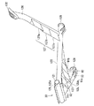
センタースタンド構造69は、車体5に揺動自在に支持され、かつ後輪8を支持する中空なスイングアーム9と、スイングアーム9内に設けられ、後輪8の駆動力を生じるモータ3と、スイングアーム9内に設けられ、モータ3に電力を供給して発熱する発熱機器としてのインバータ18と、車体5に設けられ、車体5を起立状態に維持する起立状態(図2)と、収納状態(図1、図4)との間で移動可能であり、スイングアーム9の前下方に配置されるセンタースタンド33と、センタースタンド33に設けられ、センタースタンド33が収納状態にあると、走行風をスイングアーム9へ導く導風板91と、を備えている。   The center stand structure 69 is swingably supported by the vehicle body 5 and has a hollow swing arm 9 that supports the rear wheel 8. The motor 3 is provided in the swing arm 9 and generates a driving force for the rear wheel 8. An inverter 18 as a heat generating device that is provided in the swing arm 9 and generates heat by supplying electric power to the motor 3, a standing state (FIG. 2) that is provided in the vehicle body 5 and maintains the vehicle body 5 in an upright state, and a storage state (FIGS. 1 and 4), and a center stand 33 disposed on the front lower side of the swing arm 9 and the center stand 33. When the center stand 33 is in the stowed state, And a wind guide plate 91 that guides the swing arm 9 to the swing arm 9.

モータ3およびインバータ18は、アーム部77、つまり左側のアーム73とカバー75とが区画する駆動ユニット収容部に収容されている。   The motor 3 and the inverter 18 are housed in the arm unit 77, that is, in the drive unit housing part in which the left arm 73 and the cover 75 are partitioned.

モータ3は、アーム73内のモータ室78に固定される環状の固定子95と、固定子95の中心部に配置される円盤状の回転子96と、回転子96の中心を貫くモータ軸97と、を備えている。モータ3は、回転駆動によって発熱する。   The motor 3 includes an annular stator 95 fixed to a motor chamber 78 in the arm 73, a disk-like rotor 96 disposed at the center of the stator 95, and a motor shaft 97 that penetrates the center of the rotor 96. And. The motor 3 generates heat by rotational driving.

モータ軸97は、回転子96に回転一体に固定されている。モータ軸97の一方の端部は、アーム73と後輪8との間に設けられる減速機(図示省略)に連結されて支持されている。モータ軸97の他方の端部は、カバー75に設けられるベアリング(図示省略)によって回転自在に支持されている。モータ軸97の他方の端部は、カバー75を貫通してカバー75の外側に到達している。モータ軸97の他方の端部は、カバー75に固定されるキャップ98に覆い隠されている。   The motor shaft 97 is fixed to the rotor 96 so as to rotate together. One end of the motor shaft 97 is connected to and supported by a reduction gear (not shown) provided between the arm 73 and the rear wheel 8. The other end of the motor shaft 97 is rotatably supported by a bearing (not shown) provided on the cover 75. The other end of the motor shaft 97 passes through the cover 75 and reaches the outside of the cover 75. The other end of the motor shaft 97 is covered with a cap 98 fixed to the cover 75.

インバータ18は、インバータ回路101と、インバータ回路101を制御する制御回路102と、を備えている。インバータ18は、燃料電池2または二次電池16から供給される直流電力を三相交流電力に変換してモータ3へ出力し、モータ3を運転する。インバータ18は、電力変換にともなって発熱する発熱機器である。   The inverter 18 includes an inverter circuit 101 and a control circuit 102 that controls the inverter circuit 101. The inverter 18 converts the DC power supplied from the fuel cell 2 or the secondary battery 16 into three-phase AC power and outputs it to the motor 3 to operate the motor 3. The inverter 18 is a heat generating device that generates heat in accordance with power conversion.

車体5を覆う外装12は、フットボード31の下方に設けられるフットボードロアカバー115と、フレーム11の底部を覆うアンダーカバー116と、アンダーカバー116の後方に設けられるリアロアフェンダーカバー117と、を含んでいる。   The exterior 12 that covers the vehicle body 5 includes a footboard lower cover 115 that is provided below the footboard 31, an undercover 116 that covers the bottom of the frame 11, and a rear lower fender cover 117 that is provided behind the undercover 116. It is out.

フットボードロアカバー115は、フットボード31の外縁部に沿って前後に延びている。   The footboard lower cover 115 extends back and forth along the outer edge of the footboard 31.

アンダーカバー116は、燃料タンク15、および左右の下部フレーム24を下側から覆っている。   The under cover 116 covers the fuel tank 15 and the left and right lower frames 24 from below.

リアロアフェンダーカバー117は、フレームカバー43の下方に、左右一対に設けられてタイヤハウス領域37の前端部に配置され、ピボット軸26に支えられるスイングアーム9の前端部を左右から挟んで保護している。   The rear lower fender cover 117 is provided below the frame cover 43 in a pair of left and right and disposed at the front end of the tire house region 37, and protects the front end of the swing arm 9 supported by the pivot shaft 26 by sandwiching it from the left and right. ing.

センタースタンド33は、車体5に対して略垂直に起立し、車体5を自立させる起立状体と、車体5に対して略水平に倒れ、車体5の走行を許す収納状態との間で揺動する。   The center stand 33 stands substantially vertically with respect to the vehicle body 5 and swings between an upright body that makes the vehicle body 5 self-supporting and a storage state that falls substantially horizontally with respect to the vehicle body 5 and allows the vehicle body 5 to travel. To do.

センタースタンド33は、互いに溶接される複数の管状の部材を有している。センタースタンド33は、揺動中心となる前端パイプ121と、左右一対のレッグ部122、123と、左右のレッグ部122、123の間に架設されるクロスメンバー部125と、を備えている。   The center stand 33 has a plurality of tubular members that are welded together. The center stand 33 includes a front end pipe 121 serving as a swing center, a pair of left and right leg portions 122 and 123, and a cross member portion 125 installed between the left and right leg portions 122 and 123.

また、センタースタンド33は、左側部に設けられ、踏み付け操作に使用される踏み付けアーム126と、踏み付けアーム126に設けられる第二導風板127と、を備えている。   The center stand 33 includes a stepping arm 126 provided on the left side and used for a stepping operation, and a second air guide plate 127 provided on the stepping arm 126.

前端パイプ121は、ガードフレーム29によって回転自在に支持されている。詳細には、前端パイプ121は、ガードフレーム29の後下部に車両の左右方向に沿って配置される軸(図示省略)によって回転自在に支持されている。   The front end pipe 121 is rotatably supported by the guard frame 29. Specifically, the front end pipe 121 is rotatably supported by a shaft (not shown) disposed along the left-right direction of the vehicle at the lower rear portion of the guard frame 29.

左右のレッグ部122、123は、前端パイプ121の左右それぞれの端部から左右それぞれの方向へ間隔を拡げるように延びる一対の管である。レッグ部122、123のそれぞれの自由端部には、接地片129が設けられている。   The left and right leg portions 122 and 123 are a pair of tubes that extend from the left and right ends of the front end pipe 121 so as to increase the distance in the left and right directions. A ground piece 129 is provided at each free end of the leg portions 122 and 123.

クロスメンバー部125は、車体5の幅方向へ延びる管であり、左右のレッグ部122、123に架設されている。クロスメンバー部125は複数あっても良い。本実施形態では、クロスメンバー部125は、左右のレッグ部122、123の全長を三分割するように、2箇所に架設されている(クロスメンバー部125a、125b)。前端パイプ121から最も遠いクロスメンバー部125bより後ろ側には、左右の接地片129、左右のレッグ部122、123、およびクロスメンバー部125bを連結する補強板131が設けられている。   The cross member portion 125 is a tube extending in the width direction of the vehicle body 5 and is installed on the left and right leg portions 122 and 123. There may be a plurality of cross member portions 125. In this embodiment, the cross member part 125 is constructed in two places so that the full length of the leg parts 122 and 123 on either side may be divided into three (cross member part 125a, 125b). On the rear side of the cross member portion 125b farthest from the front end pipe 121, left and right grounding pieces 129, left and right leg portions 122 and 123, and a reinforcing plate 131 for connecting the cross member portion 125b are provided.

踏み付けアーム126は、センタースタンド33を収納した際、走行の邪魔にならない範囲で車体5の左側方へ突出し、スイングアーム9のアーム73の左側面よりも左側へ突出している。踏み付けアーム126は、左のレッグ部122の自由端近くに接続され、センタースタンド33の収納状態において左のレッグ部122の後端部からスイングアーム9のアーム73の左側前方を上方へ向かって延びている。踏み付けアーム126の自由端部には踏み付け板132が設けられている。   When the center stand 33 is stored, the stepping arm 126 protrudes to the left side of the vehicle body 5 within a range that does not interfere with traveling, and protrudes to the left side from the left side surface of the arm 73 of the swing arm 9. The stepping arm 126 is connected near the free end of the left leg portion 122 and extends upward from the rear end portion of the left leg portion 122 to the front left side of the arm 73 of the swing arm 9 in the retracted state of the center stand 33. ing. A tread plate 132 is provided at the free end of the tread arm 126.

導風板91は、クロスメンバー部125に設けられている。導風板91は、クロスメンバー部125が複数ある場合(クロスメンバー部125a、125b)には、いずれかのクロスメンバー部125だけに設けられていても良いし、全てのクロスメンバー部125に設けられていても良い。また、導風板91は、一つのクロスメンバー部125に複数設けられていても良い。本実施形態に係るクロスメンバー部125は、左右のレッグ部122、123の根元に近いクロスメンバー部125aに一つの導風板91aを備え、左右のレッグ部122、123の自由端部に近いクロスメンバー部125bに複数、具体的には二つの導風板91b、91cを備えている。   The air guide plate 91 is provided in the cross member portion 125. When there are a plurality of cross member portions 125 (cross member portions 125a and 125b), the air guide plate 91 may be provided only in one of the cross member portions 125, or provided in all the cross member portions 125. It may be done. A plurality of air guide plates 91 may be provided on one cross member portion 125. The cross member part 125 according to the present embodiment includes a single air guide plate 91a on the cross member part 125a near the base of the left and right leg parts 122, 123, and is a cross near the free ends of the left and right leg parts 122, 123. The member portion 125b is provided with a plurality of, specifically, two air guide plates 91b and 91c.

導風板91は、収納状態においてクロスメンバー部125から前下方に延びている。導風板91の前縁部92は、スイングアーム9前方の外装12よりも下方に突出し、車体5の下方に流れる走行風をスイングアーム9へ向けて後上方へ偏向させる。つまり、導風板91は、スイングアーム9へ向かって上下方向に傾けられている。   The air guide plate 91 extends forward and downward from the cross member portion 125 in the housed state. The front edge portion 92 of the air guide plate 91 protrudes below the exterior 12 in front of the swing arm 9 and deflects the traveling wind flowing below the vehicle body 5 toward the swing arm 9 in the rear upper direction. That is, the air guide plate 91 is inclined in the vertical direction toward the swing arm 9.

また、導風板91は、走行風をスイングアーム9のアーム73へ向かって偏向するよう、車体5の幅方向へも傾いていても良い。走行風をスイングアーム9のアーム73へ偏向させるために、導風板91に偏向板133が設けられていても良い。センタースタンド構造69は、導風板91によって走行風をスイングアーム9のアーム73に当てて、発熱機器としてのインバータ18や、発熱するモータ3を効率的に冷却する。   Further, the air guide plate 91 may be inclined in the width direction of the vehicle body 5 so as to deflect the traveling wind toward the arm 73 of the swing arm 9. In order to deflect the traveling wind toward the arm 73 of the swing arm 9, a deflecting plate 133 may be provided on the air guide plate 91. The center stand structure 69 applies the traveling wind to the arm 73 of the swing arm 9 by the air guide plate 91 to efficiently cool the inverter 18 as the heat generating device and the motor 3 that generates heat.

なお、センタースタンド構造69は、導風板91を左右のレッグ部122、123の少なくとも一方からクロスメンバー部125に跨がせ、溶接などの固定方法で両方に固定することによって、センタースタンド33自体の補強にも資する。   In addition, the center stand structure 69 has the center stand 33 itself by straddling the air guide plate 91 from at least one of the left and right leg portions 122 and 123 to the cross member portion 125 and fixing them to both by a fixing method such as welding. Contribute to the reinforcement of.

第二導風板127は、複数設けられていても良い。本実施形態に係るセンタースタンド構造69は、踏み付けアーム126に3つの第二導風板127a、127b、127cを備えている。   A plurality of second air guide plates 127 may be provided. The center stand structure 69 according to this embodiment includes three second air guide plates 127a, 127b, and 127c on the stepping arm 126.

第二導風板127は、収納状態において踏み付けアーム126から左前方に延びている。第二導風板127の前縁部128は、スイングアーム9前方の外装12よりも左方に突出し、車体5の左方に流れる走行風をスイングアーム9へ向けて右後方へ偏向させる。つまり、第二導風板127は、スイングアーム9へ向かって左右方向に傾けられている。   The second air guide plate 127 extends leftward and forward from the stepping arm 126 in the stored state. The front edge portion 128 of the second air guide plate 127 protrudes leftward from the exterior 12 in front of the swing arm 9 and deflects the traveling wind flowing to the left of the vehicle body 5 toward the swing arm 9 to the right rear. That is, the second air guide plate 127 is inclined in the left-right direction toward the swing arm 9.

また、第二導風板127は、走行風をスイングアーム9のアーム73へ向かって偏向するよう、車体3の上下方向へも傾いている。走行風をスイングアーム9のアーム73へ偏向させるために、第二導風板127に第二偏向板135が設けられていても良い。センタースタンド構造69は、導風板91および第二導風板127によって走行風をスイングアーム9のアーム73に当てて、発熱機器としてのインバータ18や、発熱するモータ3を効率的に冷却する。特に、第二導風板127は、スイングアーム9の左側面よりも左側へ延びる踏み付けアーム126に設けられているため、アーム73の左側面へも走行風を偏向させることができる。   The second air guide plate 127 is also inclined in the vertical direction of the vehicle body 3 so as to deflect the traveling wind toward the arm 73 of the swing arm 9. In order to deflect the traveling wind toward the arm 73 of the swing arm 9, a second deflecting plate 135 may be provided on the second air guide plate 127. The center stand structure 69 applies the traveling wind to the arm 73 of the swing arm 9 by the wind guide plate 91 and the second wind guide plate 127 to efficiently cool the inverter 18 as the heat generating device and the motor 3 that generates heat. In particular, since the second air guide plate 127 is provided on the stepping arm 126 that extends to the left side of the left side surface of the swing arm 9, the traveling wind can be deflected to the left side surface of the arm 73.

なお、センタースタンド構造69は、第二導風板127を踏み付けアーム126から左のレッグ部122に跨がせ、溶接などの固定方法で両方に固定することによって、センタースタンド33自体の補強にも資する。   The center stand structure 69 is also used to reinforce the center stand 33 itself by straddling the second air guide plate 127 from the arm 126 to the left leg portion 122 and fixing it to both by a fixing method such as welding. To contribute.

本実施形態に係る電動二輪車1のセンタースタンド構造69は、センタースタンド33に導風板91を設けることによって、走行風をスイングアーム9へ効果的に当ててモータ3やインバータ18を冷却することができる。   The center stand structure 69 of the electric motorcycle 1 according to the present embodiment can cool the motor 3 and the inverter 18 by effectively applying traveling wind to the swing arm 9 by providing the center stand 33 with the air guide plate 91. it can.

また、本実施形態に係る電動二輪車1のセンタースタンド構造69は、導風板91を車体5の幅方向へ延びるクロスメンバー部125に設けることによって、より広範囲から走行風を集めるようにして、大流量の走行風をスイングアーム9へ偏向することができる。   Further, the center stand structure 69 of the electric motorcycle 1 according to the present embodiment has a large wind guide plate 91 provided on the cross member portion 125 extending in the width direction of the vehicle body 5 so as to collect traveling wind from a wider range. It is possible to deflect the traveling airflow at a flow rate to the swing arm 9.

さらに、本実施形態に係る電動二輪車1のセンタースタンド構造69は、導風板91の前縁部92をスイングアーム9前方の外装12よりも下方に突出させることで、車体5の下方に流れる走行風をスイングアーム9へ向けて偏向させることができる。   Furthermore, the center stand structure 69 of the electric motorcycle 1 according to the present embodiment travels below the vehicle body 5 by causing the front edge portion 92 of the air guide plate 91 to protrude downward from the exterior 12 in front of the swing arm 9. The wind can be deflected toward the swing arm 9.

さらにまた、本実施形態に係る電動二輪車1のセンタースタンド構造69は、踏み付けアーム126に第二導風板127を備えることで、スイングアーム9の側面を効果的に冷却できる。   Furthermore, the center stand structure 69 of the electric motorcycle 1 according to the present embodiment can cool the side surface of the swing arm 9 effectively by providing the stepping arm 126 with the second air guide plate 127.

したがって、本発明に係る電動二輪車1のセンタースタンド構造69は、走行風によってスイングアーム9を効率的に冷却し、ひいてはモータ3および発熱機器としてのインバータ18を効果的に冷却できる。   Therefore, the center stand structure 69 of the electric motorcycle 1 according to the present invention can efficiently cool the swing arm 9 by traveling wind, and can effectively cool the motor 3 and the inverter 18 as a heat generating device.

1…燃料電池二輪車、2…燃料電池、2a…吸気口、2b…排気口、3…モータ、5…車体、6…前輪、7…ステアリング機構、8…後輪、9…スイングアーム、11…フレーム、12…外装、13…シート、13a…前方部、13b…後方部、15…燃料タンク、16…二次電池、17…電力管理装置、18…インバータ、19…車両コントローラ、21…ヘッドパイプ、22…上部ダウンフレーム、23…下部ダウンフレーム、24…下部フレーム、25…上部フレーム、26…ピボット軸、26a…ブラケット、27…上ブリッジフレーム、28…下ブリッジフレーム、29…ガードフレーム、30…搭載機器保護フレーム、30a…前保護フレーム、30b…中央保護フレーム、30c…後保護フレーム、30d…側部保護フレーム、30e…ブラケット、30f…継手用ブラケット、31…フットボード、31a…フットレストブラケット、33…センタースタンド、34…ヘッドパイプ近傍ブリッジフレーム、35…センタートンネル領域、36…機器搭載領域、37…タイヤハウス領域、38…リアフェンダ、41…フロントレッグシールドカバー、42…フロントフレームカバー、43…フレームカバー、45…ハンドル、46…フロントフォーク、47…フロントフェンダ、48…リアサスペンション、52…排気ダクト、52a…排気口、55…圧力容器、56…燃料充填口、57…燃料充填用継手、58…燃料充填元弁、59…燃料供給元弁、61…クランプバンド、62…燃料充填口用リッド、63…タンクバルブ、69…センタースタンド構造、72…ピボット部、73…アーム、75…カバー、76…アーム、77…アーム部、78…モータ室、79…インバータ室、81…底面、82…放熱フィン、91、91a、91b、91c…導風板、92…前縁部、95…固定子、96…回転子、97…モータ軸、98…キャップ、101…インバータ回路、102…制御回路、115…フットボードロアカバー、116…アンダーカバー、117…リアロアフェンダーカバー、121…前端パイプ、122、123…レッグ部、125、125a、125b…クロスメンバー部、126…踏み付けアーム、127、127a、127b、127c…第二導風板、128…前縁部、129…接地片、131…補強板、132…踏み付け板、133…偏向板、135…第二偏向板。   DESCRIPTION OF SYMBOLS 1 ... Fuel cell motorcycle, 2 ... Fuel cell, 2a ... Intake port, 2b ... Exhaust port, 3 ... Motor, 5 ... Vehicle body, 6 ... Front wheel, 7 ... Steering mechanism, 8 ... Rear wheel, 9 ... Swing arm, 11 ... Frame, 12 ... exterior, 13 ... seat, 13a ... front part, 13b ... rear part, 15 ... fuel tank, 16 ... secondary battery, 17 ... power management device, 18 ... inverter, 19 ... vehicle controller, 21 ... head pipe 22 ... Upper down frame, 23 ... Lower down frame, 24 ... Lower frame, 25 ... Upper frame, 26 ... Pivot shaft, 26a ... Bracket, 27 ... Upper bridge frame, 28 ... Lower bridge frame, 29 ... Guard frame, 30 ... Equipment protection frame, 30a ... Front protection frame, 30b ... Center protection frame, 30c ... Rear protection frame, 30d ... Side protection frame 30e ... Bracket, 30f ... Bracket for joint, 31 ... Footboard, 31a ... Footrest bracket, 33 ... Center stand, 34 ... Bridge frame near the head pipe, 35 ... Center tunnel area, 36 ... Equipment mounting area, 37 ... Tire house area 38 ... Rear fender, 41 ... Front leg shield cover, 42 ... Front frame cover, 43 ... Frame cover, 45 ... Handle, 46 ... Front fork, 47 ... Front fender, 48 ... Rear suspension, 52 ... Exhaust duct, 52a ... Exhaust 55, pressure vessel, 56 ... fuel filling port, 57 ... fuel filling joint, 58 ... fuel filling source valve, 59 ... fuel supply source valve, 61 ... clamp band, 62 ... fuel filling port lid, 63 ... tank Valve, 69 ... Center stand structure, 72 ... Bot part, 73 ... Arm, 75 ... Cover, 76 ... Arm, 77 ... Arm part, 78 ... Motor room, 79 ... Inverter room, 81 ... Bottom, 82 ... Radiation fin, 91, 91a, 91b, 91c ... Air guide plate , 92 ... Front edge part, 95 ... Stator, 96 ... Rotor, 97 ... Motor shaft, 98 ... Cap, 101 ... Inverter circuit, 102 ... Control circuit, 115 ... Footboard lower cover, 116 ... Under cover, 117 ... Rear Lower fender cover, 121 ... front end pipe, 122, 123 ... leg part, 125, 125a, 125b ... cross member part, 126 ... tread arm, 127, 127a, 127b, 127c ... second air guide plate, 128 ... front edge part 129: Grounding piece 131: Reinforcing plate 132: Treading plate 133: Deflection plate 135: Second deflection plate

Claims (4)

車体に揺動自在に支持され、かつ駆動輪を支持する中空なスイングアームと、
前記スイングアーム内に設けられ、前記駆動輪の駆動力を生じるモータと、
前記スイングアーム内に設けられ、前記モータに電力を供給して発熱する発熱機器と、
前記車体に設けられ、前記車体を起立状態に維持する起立状態と、収納状態との間で移動可能であり、前記スイングアームの前下方に配置されるセンタースタンドと、
前記センタースタンドに設けられ、前記センタースタンドが前記収納状態にあると、走行風を前記スイングアームへ導く導風板と、を備える電動二輪車のセンタースタンド構造。
A hollow swing arm supported swingably on the vehicle body and supporting the drive wheel;
A motor that is provided in the swing arm and generates a driving force of the driving wheel;
A heat generating device provided in the swing arm and generating heat by supplying power to the motor;
A center stand provided on the vehicle body, movable between an upright state for maintaining the vehicle body in an upright state and a stored state, and disposed at a front lower side of the swing arm;
A center stand structure for an electric motorcycle, comprising: a wind guide plate that is provided on the center stand and guides traveling wind to the swing arm when the center stand is in the stored state.
前記センタースタンドは、左右一対のレッグ部と、前記左右のレッグ部の間に架設されるクロスメンバー部と、を備え
前記導風板は、前記クロスメンバー部に設けられている請求項1に記載の電動二輪車のセンタースタンド構造。
The said center stand is provided with a pair of right and left leg parts, and a cross member part constructed between the said left and right leg parts, The said baffle plate is provided in the said cross member part. The center stand structure for electric motorcycles.
前記車体は、前記スイングアームの前方を覆う外装を備え、
前記導風板の前縁部は、前記スイングアーム前方の前記外装よりも下方に突出し、前記車体の下方に流れる走行風を前記スイングアームへ向けて後上方へ偏向させる請求項1または2に記載の電動二輪車のセンタースタンド構造。
The vehicle body includes an exterior covering the front of the swing arm,
The front edge part of the said baffle plate protrudes below the said exterior in front of the said swing arm, and deflects the driving | running | working wind which flows below the said vehicle body toward the said swing arm back upwards. The center stand structure for electric motorcycles.
前記スイングアームは、前記モータおよび前記発熱機器を前記駆動輪の左側に収容し、
前記センタースタンドは、左側部に設けられ、踏み付け操作に使用される踏み付けアームを備え、
前記アームに設けられる第二導風板を備える請求項1から3のいずれか1項に記載の電動二輪車のセンタースタンド構造。
The swing arm accommodates the motor and the heat generating device on the left side of the drive wheel,
The center stand is provided on the left side and includes a stepping arm used for a stepping operation.
The center stand structure of the electric motorcycle according to any one of claims 1 to 3, further comprising a second air guide plate provided on the arm.
JP2015240021A 2015-12-09 2015-12-09 Center stand structure of two-wheeled electric vehicle Pending JP2017105293A (en)

Priority Applications (1)

Application Number Priority Date Filing Date Title
JP2015240021A JP2017105293A (en) 2015-12-09 2015-12-09 Center stand structure of two-wheeled electric vehicle

Applications Claiming Priority (1)

Application Number Priority Date Filing Date Title
JP2015240021A JP2017105293A (en) 2015-12-09 2015-12-09 Center stand structure of two-wheeled electric vehicle

Publications (1)

Publication Number Publication Date
JP2017105293A true JP2017105293A (en) 2017-06-15

Family

ID=59058546

Family Applications (1)

Application Number Title Priority Date Filing Date
JP2015240021A Pending JP2017105293A (en) 2015-12-09 2015-12-09 Center stand structure of two-wheeled electric vehicle

Country Status (1)

Country Link
JP (1) JP2017105293A (en)

Cited By (4)

* Cited by examiner, † Cited by third party
Publication number Priority date Publication date Assignee Title
WO2020161938A1 (en) * 2019-02-08 2020-08-13 本田技研工業株式会社 Rectification structure for saddle-type vehicle
WO2021157211A1 (en) * 2020-02-07 2021-08-12 本田技研工業株式会社 Saddle-type vehicle
CN113911257A (en) * 2021-10-27 2022-01-11 浙江绿源电动车有限公司 A heat dissipation structure for a mid-mounted motor
JP2022191074A (en) * 2021-06-15 2022-12-27 本田技研工業株式会社 Saddle riding type vehicle

Cited By (9)

* Cited by examiner, † Cited by third party
Publication number Priority date Publication date Assignee Title
WO2020161938A1 (en) * 2019-02-08 2020-08-13 本田技研工業株式会社 Rectification structure for saddle-type vehicle
JPWO2020161938A1 (en) * 2019-02-08 2021-10-28 本田技研工業株式会社 Rectifying structure for saddle-mounted vehicles
JP7241780B2 (en) 2019-02-08 2023-03-17 本田技研工業株式会社 Rectification structure of saddle type vehicle
WO2021157211A1 (en) * 2020-02-07 2021-08-12 本田技研工業株式会社 Saddle-type vehicle
JPWO2021157211A1 (en) * 2020-02-07 2021-08-12
JP7326496B2 (en) 2020-02-07 2023-08-15 本田技研工業株式会社 straddle-type vehicle
JP2022191074A (en) * 2021-06-15 2022-12-27 本田技研工業株式会社 Saddle riding type vehicle
JP7340564B2 (en) 2021-06-15 2023-09-07 本田技研工業株式会社 saddle type vehicle
CN113911257A (en) * 2021-10-27 2022-01-11 浙江绿源电动车有限公司 A heat dissipation structure for a mid-mounted motor

Similar Documents

Publication Publication Date Title
JP6561770B2 (en) Electric vehicle structure
JP6536353B2 (en) Converter arrangement structure of electric vehicle
US8622163B2 (en) Scooter type motorcycle equipped with fuel cell system
JP5417992B2 (en) Fuel cell vehicle
JP6555074B2 (en) Cooling structure of power conversion device for electric motorcycle
JP2017082871A (en) Drive device of electric two-wheeled vehicle, and method of assembling drive device of electric two-wheeled vehicle
JP2017081326A (en) Piping joint arrangement structure for fuel cell motorcycles
JP2017081324A (en) Battery system for electric motorcycles
JP2017105293A (en) Center stand structure of two-wheeled electric vehicle
JP5807481B2 (en) Cooling device for vehicle drive motor
JP6561769B2 (en) Exhaust duct structure for fuel cell vehicles
JP6648518B2 (en) Hydrogen dilution equipment for fuel cell vehicles
JP6661968B2 (en) Drainage structure of electric motorcycle
JP6536351B2 (en) Swing arm of electric motorcycle
JP5407546B2 (en) Fuel cell vehicle
JP2011255827A (en) Fuel cell motorcycle
JP6696293B2 (en) Electric motorcycle
JP2017081330A (en) Exterior structure for electric two-wheel vehicle
JP6880639B2 (en) Support structure of fuel tank of fuel cell vehicle
JP2017081328A (en) Driving device of electric vehicle
JP2017154666A (en) Body structure of fuel cell two-wheel vehicle
JP2009154565A (en) Pillion step mounting structure for motorcycles
JP2018111441A (en) Fuel pipe connection structure of fuel cell vehicle
JP2017084546A (en) Exhaust duct structure for fuel cell vehicles