JP2017106730A - 角度検出装置及び測量装置 - Google Patents
角度検出装置及び測量装置 Download PDFInfo
- Publication number
- JP2017106730A JP2017106730A JP2015238381A JP2015238381A JP2017106730A JP 2017106730 A JP2017106730 A JP 2017106730A JP 2015238381 A JP2015238381 A JP 2015238381A JP 2015238381 A JP2015238381 A JP 2015238381A JP 2017106730 A JP2017106730 A JP 2017106730A
- Authority
- JP
- Japan
- Prior art keywords
- angle
- unit
- rotation
- light
- absolute encoder
- Prior art date
- Legal status (The legal status is an assumption and is not a legal conclusion. Google has not performed a legal analysis and makes no representation as to the accuracy of the status listed.)
- Granted
Links
Images


Classifications
-
- G—PHYSICS
- G01—MEASURING; TESTING
- G01D—MEASURING NOT SPECIALLY ADAPTED FOR A SPECIFIC VARIABLE; ARRANGEMENTS FOR MEASURING TWO OR MORE VARIABLES NOT COVERED IN A SINGLE OTHER SUBCLASS; TARIFF METERING APPARATUS; MEASURING OR TESTING NOT OTHERWISE PROVIDED FOR
- G01D5/00—Mechanical means for transferring the output of a sensing member; Means for converting the output of a sensing member to another variable where the form or nature of the sensing member does not constrain the means for converting; Transducers not specially adapted for a specific variable
- G01D5/26—Mechanical means for transferring the output of a sensing member; Means for converting the output of a sensing member to another variable where the form or nature of the sensing member does not constrain the means for converting; Transducers not specially adapted for a specific variable characterised by optical transfer means, i.e. using infrared, visible, or ultraviolet light
- G01D5/32—Mechanical means for transferring the output of a sensing member; Means for converting the output of a sensing member to another variable where the form or nature of the sensing member does not constrain the means for converting; Transducers not specially adapted for a specific variable characterised by optical transfer means, i.e. using infrared, visible, or ultraviolet light with attenuation or whole or partial obturation of beams of light
- G01D5/34—Mechanical means for transferring the output of a sensing member; Means for converting the output of a sensing member to another variable where the form or nature of the sensing member does not constrain the means for converting; Transducers not specially adapted for a specific variable characterised by optical transfer means, i.e. using infrared, visible, or ultraviolet light with attenuation or whole or partial obturation of beams of light the beams of light being detected by photocells
- G01D5/347—Mechanical means for transferring the output of a sensing member; Means for converting the output of a sensing member to another variable where the form or nature of the sensing member does not constrain the means for converting; Transducers not specially adapted for a specific variable characterised by optical transfer means, i.e. using infrared, visible, or ultraviolet light with attenuation or whole or partial obturation of beams of light the beams of light being detected by photocells using displacement encoding scales
- G01D5/34776—Absolute encoders with analogue or digital scales
-
- G—PHYSICS
- G01—MEASURING; TESTING
- G01S—RADIO DIRECTION-FINDING; RADIO NAVIGATION; DETERMINING DISTANCE OR VELOCITY BY USE OF RADIO WAVES; LOCATING OR PRESENCE-DETECTING BY USE OF THE REFLECTION OR RERADIATION OF RADIO WAVES; ANALOGOUS ARRANGEMENTS USING OTHER WAVES
- G01S17/00—Systems using the reflection or reradiation of electromagnetic waves other than radio waves, e.g. lidar systems
- G01S17/02—Systems using the reflection of electromagnetic waves other than radio waves
- G01S17/06—Systems determining position data of a target
- G01S17/42—Simultaneous measurement of distance and other co-ordinates
-
- G—PHYSICS
- G01—MEASURING; TESTING
- G01C—MEASURING DISTANCES, LEVELS OR BEARINGS; SURVEYING; NAVIGATION; GYROSCOPIC INSTRUMENTS; PHOTOGRAMMETRY OR VIDEOGRAMMETRY
- G01C3/00—Measuring distances in line of sight; Optical rangefinders
- G01C3/02—Details
- G01C3/06—Use of electric means to obtain final indication
- G01C3/08—Use of electric radiation detectors
-
- G—PHYSICS
- G01—MEASURING; TESTING
- G01S—RADIO DIRECTION-FINDING; RADIO NAVIGATION; DETERMINING DISTANCE OR VELOCITY BY USE OF RADIO WAVES; LOCATING OR PRESENCE-DETECTING BY USE OF THE REFLECTION OR RERADIATION OF RADIO WAVES; ANALOGOUS ARRANGEMENTS USING OTHER WAVES
- G01S17/00—Systems using the reflection or reradiation of electromagnetic waves other than radio waves, e.g. lidar systems
- G01S17/02—Systems using the reflection of electromagnetic waves other than radio waves
- G01S17/06—Systems determining position data of a target
- G01S17/08—Systems determining position data of a target for measuring distance only
- G01S17/10—Systems determining position data of a target for measuring distance only using transmission of interrupted, pulse-modulated waves
-
- G—PHYSICS
- G01—MEASURING; TESTING
- G01S—RADIO DIRECTION-FINDING; RADIO NAVIGATION; DETERMINING DISTANCE OR VELOCITY BY USE OF RADIO WAVES; LOCATING OR PRESENCE-DETECTING BY USE OF THE REFLECTION OR RERADIATION OF RADIO WAVES; ANALOGOUS ARRANGEMENTS USING OTHER WAVES
- G01S7/00—Details of systems according to groups G01S13/00, G01S15/00, G01S17/00
- G01S7/48—Details of systems according to groups G01S13/00, G01S15/00, G01S17/00 of systems according to group G01S17/00
- G01S7/481—Constructional features, e.g. arrangements of optical elements
- G01S7/4817—Constructional features, e.g. arrangements of optical elements relating to scanning
-
- G—PHYSICS
- G01—MEASURING; TESTING
- G01C—MEASURING DISTANCES, LEVELS OR BEARINGS; SURVEYING; NAVIGATION; GYROSCOPIC INSTRUMENTS; PHOTOGRAMMETRY OR VIDEOGRAMMETRY
- G01C15/00—Surveying instruments or accessories not provided for in groups G01C1/00 - G01C13/00
- G01C15/002—Active optical surveying means
Landscapes
- Physics & Mathematics (AREA)
- Engineering & Computer Science (AREA)
- Electromagnetism (AREA)
- General Physics & Mathematics (AREA)
- Radar, Positioning & Navigation (AREA)
- Remote Sensing (AREA)
- Computer Networks & Wireless Communication (AREA)
- Length Measuring Devices By Optical Means (AREA)
- Transmission And Conversion Of Sensor Element Output (AREA)
- Optical Transform (AREA)
Abstract
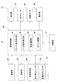
【解決手段】等速回転する回転部に設けられたアブソリュートエンコーダと、クロック信号発生部41と、カウンタ回路44と、角度演算部43と、トリガ信号発生部42とを具備し、角度トリガ信号が所定時間間隔でアブソリュートエンコーダ及びカウンタ回路44に入力され、アブソリュートエンコーダは各角度トリガ信号毎の回転角度を角度演算部43に入力し、回転部の回転角度を検出する為の回転角測定トリガ信号がカウンタ回路44に入力されることで、カウンタ回路44は角度トリガ信号が入力された時点からのクロックカウント数を角度演算部43に出力し、角度演算部43はアブソリュートエンコーダからの回転角度とクロックカウント数に基づき回転部の回転角度を検出する様構成した。
【選択図】図2
Description
θ=[(tj −ti )/((ti+1 )−ti )]×(φ(i+1 )−φi )+φi で得られる。
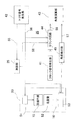
2 測定装置本体
12 回転部
13 偏向ミラー
14 水平角エンコーダ
16 検出部
19 水平モータ
20 鉛直モータ
24 撮像素子
25 測距部
27 発光部
28 測距受光素子
33 鉛直角エンコーダ
35 演算制御部
36 角度測定部
41 クロック信号発生部
42 トリガ信号発生部
43 角度演算部
44 カウンタ回路
45 角度検出部
51 発光素子
52 走査盤
55 制御信号
56 角度トリガ信号
57 主検出角度
58 受光検出信号
59 カウント信号
Claims (3)
- 等速回転する回転部に設けられたアブソリュートエンコーダと、クロック信号発生部と、カウンタ回路と、角度演算部と、トリガ信号発生部とを具備し、角度トリガ信号が所定時間間隔で前記アブソリュートエンコーダ及び前記カウンタ回路に入力され、前記アブソリュートエンコーダは各角度トリガ信号毎の回転角度を前記角度演算部に入力し、前記回転部の回転角度を検出する為の回転角測定トリガ信号が前記カウンタ回路に入力されることで、該カウンタ回路は前記角度トリガ信号が入力された時点からのクロックカウント数を前記角度演算部に出力し、該角度演算部は前記アブソリュートエンコーダからの回転角度と前記クロックカウント数に基づき前記回転部の回転角度を検出する様構成した角度検出装置。
- 前記回転部が停止状態、或は該回転部の回転速度が前記アブソリュートエンコーダの角度検出応答速度より遅い回転速度である場合は、該アブソリュートエンコーダが検出する回転角度を前記回転部の回転角度とする請求項1に記載の角度検出装置。
- 測距光をパルス発光し、照射する投光部と、反射測距光を受光して受光信号を発する受光部と、該受光部からの受光信号に基づき測距を行う測距部と、前記測距光を水平方向に偏向し、等速で水平方向、鉛直方向に回転され、前記測距光を回転照射する回転偏向部と、該回転偏向部の回転角度を検出する請求項1に記載の角度検出装置と、前記測距部、前記回転偏向部を制御し、前記測距光を走査し、前記受光部からの受光信号に基づき測定点の3次元データを演算する演算制御部とを具備する測量装置。
Priority Applications (2)
| Application Number | Priority Date | Filing Date | Title |
|---|---|---|---|
| JP2015238381A JP6767107B2 (ja) | 2015-12-07 | 2015-12-07 | 角度検出装置及び測量装置 |
| US15/361,703 US10267659B2 (en) | 2015-12-07 | 2016-11-28 | Angle detecting device and surveying instrument |
Applications Claiming Priority (1)
| Application Number | Priority Date | Filing Date | Title |
|---|---|---|---|
| JP2015238381A JP6767107B2 (ja) | 2015-12-07 | 2015-12-07 | 角度検出装置及び測量装置 |
Publications (2)
| Publication Number | Publication Date |
|---|---|
| JP2017106730A true JP2017106730A (ja) | 2017-06-15 |
| JP6767107B2 JP6767107B2 (ja) | 2020-10-14 |
Family
ID=58798343
Family Applications (1)
| Application Number | Title | Priority Date | Filing Date |
|---|---|---|---|
| JP2015238381A Active JP6767107B2 (ja) | 2015-12-07 | 2015-12-07 | 角度検出装置及び測量装置 |
Country Status (2)
| Country | Link |
|---|---|
| US (1) | US10267659B2 (ja) |
| JP (1) | JP6767107B2 (ja) |
Families Citing this family (6)
| Publication number | Priority date | Publication date | Assignee | Title |
|---|---|---|---|---|
| JP6650726B2 (ja) * | 2015-10-20 | 2020-02-19 | 株式会社トプコン | 測定装置 |
| JP6650727B2 (ja) | 2015-10-20 | 2020-02-19 | 株式会社トプコン | 傾斜角測定装置 |
| JP6691419B2 (ja) * | 2016-04-15 | 2020-04-28 | 株式会社トプコン | 超音波モータの制御方法及びそのための測量機 |
| EP3570065B1 (en) * | 2018-05-16 | 2021-02-24 | Miele & Cie. KG | 3d scanning lidar sensor |
| CN113970752B (zh) * | 2020-07-22 | 2025-05-27 | 商汤集团有限公司 | 一种目标检测方法、装置、电子设备及存储介质 |
| CN117249846B (zh) * | 2023-11-17 | 2024-02-09 | 浙江明哲电子科技有限公司 | 一种编码器预解码处理方法、系统及存储介质 |
Citations (4)
| Publication number | Priority date | Publication date | Assignee | Title |
|---|---|---|---|---|
| JP2004513357A (ja) * | 2000-10-31 | 2004-04-30 | ドクトル・ヨハネス・ハイデンハイン・ゲゼルシヤフト・ミツト・ベシユレンクテル・ハフツング | 位置測定装置及び位置を測定する方法 |
| JP2008032562A (ja) * | 2006-07-28 | 2008-02-14 | Ntn Corp | 回転検出装置および回転検出装置付き軸受 |
| JP2012068243A (ja) * | 2010-09-24 | 2012-04-05 | Sick Ag | レーザスキャナ及びその製造方法 |
| JP2012093245A (ja) * | 2010-10-27 | 2012-05-17 | Topcon Corp | レーザ測量機 |
Family Cites Families (4)
| Publication number | Priority date | Publication date | Assignee | Title |
|---|---|---|---|---|
| JPS60157014A (ja) | 1984-01-26 | 1985-08-17 | Tokyo Optical Co Ltd | エンコ−ダ読取信号の内挿方法および装置 |
| JP3700325B2 (ja) * | 1997-05-21 | 2005-09-28 | 松下電器産業株式会社 | 駆動源制御方法 |
| US7215808B2 (en) * | 2004-05-04 | 2007-05-08 | Kla-Tencor Technologies Corporation | High throughout image for processing inspection images |
| DE102006009773A1 (de) * | 2006-03-01 | 2007-09-06 | Eastman Kodak Co. | Verfahren zum Vermeiden eines Passerfehlers beim Drucken |
-
2015
- 2015-12-07 JP JP2015238381A patent/JP6767107B2/ja active Active
-
2016
- 2016-11-28 US US15/361,703 patent/US10267659B2/en active Active
Patent Citations (4)
| Publication number | Priority date | Publication date | Assignee | Title |
|---|---|---|---|---|
| JP2004513357A (ja) * | 2000-10-31 | 2004-04-30 | ドクトル・ヨハネス・ハイデンハイン・ゲゼルシヤフト・ミツト・ベシユレンクテル・ハフツング | 位置測定装置及び位置を測定する方法 |
| JP2008032562A (ja) * | 2006-07-28 | 2008-02-14 | Ntn Corp | 回転検出装置および回転検出装置付き軸受 |
| JP2012068243A (ja) * | 2010-09-24 | 2012-04-05 | Sick Ag | レーザスキャナ及びその製造方法 |
| JP2012093245A (ja) * | 2010-10-27 | 2012-05-17 | Topcon Corp | レーザ測量機 |
Also Published As
| Publication number | Publication date |
|---|---|
| JP6767107B2 (ja) | 2020-10-14 |
| US10267659B2 (en) | 2019-04-23 |
| US20170160108A1 (en) | 2017-06-08 |
Similar Documents
| Publication | Publication Date | Title |
|---|---|---|
| US11650291B2 (en) | LiDAR sensor | |
| JP6767107B2 (ja) | 角度検出装置及び測量装置 | |
| EP2381272B1 (en) | Laser scanner | |
| US10031228B2 (en) | Object detecting apparatus | |
| JP5207665B2 (ja) | 測定システム | |
| JP6347674B2 (ja) | レーザスキャナシステム | |
| US9759583B2 (en) | Method of obtaining a reference correction value for an index mark of an angular encoder | |
| EP3772633B1 (en) | Surveying instrument | |
| US11789151B2 (en) | Target unit | |
| JP2018128291A (ja) | 測量システム | |
| CN110794418B (zh) | 测量装置 | |
| JP2017223541A (ja) | レーザスキャナ | |
| JP6640541B2 (ja) | レーザスキャナ | |
| US11635490B2 (en) | Surveying system having a rotating mirror | |
| JP2020056615A (ja) | 測量システム、測量機、および測量方法 | |
| JP6253932B2 (ja) | 方向検出装置及び測量システム | |
| JP5213607B2 (ja) | 基板表面変位測定装置 | |
| JP2005292037A (ja) | 角度測定装置 | |
| EP4160145B1 (en) | Surveying instrument | |
| JP2018048867A (ja) | スキャナ装置および測量装置 | |
| JP2008256463A (ja) | 計測装置及びミラー姿勢・回動監視装置 |
Legal Events
| Date | Code | Title | Description |
|---|---|---|---|
| A621 | Written request for application examination |
Free format text: JAPANESE INTERMEDIATE CODE: A621 Effective date: 20181029 |
|
| A977 | Report on retrieval |
Free format text: JAPANESE INTERMEDIATE CODE: A971007 Effective date: 20190926 |
|
| A131 | Notification of reasons for refusal |
Free format text: JAPANESE INTERMEDIATE CODE: A131 Effective date: 20191001 |
|
| A521 | Request for written amendment filed |
Free format text: JAPANESE INTERMEDIATE CODE: A523 Effective date: 20191112 |
|
| A131 | Notification of reasons for refusal |
Free format text: JAPANESE INTERMEDIATE CODE: A131 Effective date: 20200421 |
|
| A521 | Request for written amendment filed |
Free format text: JAPANESE INTERMEDIATE CODE: A523 Effective date: 20200604 |
|
| TRDD | Decision of grant or rejection written | ||
| A01 | Written decision to grant a patent or to grant a registration (utility model) |
Free format text: JAPANESE INTERMEDIATE CODE: A01 Effective date: 20200908 |
|
| A61 | First payment of annual fees (during grant procedure) |
Free format text: JAPANESE INTERMEDIATE CODE: A61 Effective date: 20200917 |
|
| R150 | Certificate of patent or registration of utility model |
Ref document number: 6767107 Country of ref document: JP Free format text: JAPANESE INTERMEDIATE CODE: R150 |
|
| R250 | Receipt of annual fees |
Free format text: JAPANESE INTERMEDIATE CODE: R250 |
|
| R250 | Receipt of annual fees |
Free format text: JAPANESE INTERMEDIATE CODE: R250 |
|
| R250 | Receipt of annual fees |
Free format text: JAPANESE INTERMEDIATE CODE: R250 |