JP2017107728A - アース端子、及び、ワイヤハーネス - Google Patents
アース端子、及び、ワイヤハーネス Download PDFInfo
- Publication number
- JP2017107728A JP2017107728A JP2015240442A JP2015240442A JP2017107728A JP 2017107728 A JP2017107728 A JP 2017107728A JP 2015240442 A JP2015240442 A JP 2015240442A JP 2015240442 A JP2015240442 A JP 2015240442A JP 2017107728 A JP2017107728 A JP 2017107728A
- Authority
- JP
- Japan
- Prior art keywords
- fastening
- ground terminal
- ground
- fastening portion
- grounding surface
- Prior art date
- Legal status (The legal status is an assumption and is not a legal conclusion. Google has not performed a legal analysis and makes no representation as to the accuracy of the status listed.)
- Granted
Links
Images
























Classifications
-
- H—ELECTRICITY
- H01—ELECTRIC ELEMENTS
- H01R—ELECTRICALLY-CONDUCTIVE CONNECTIONS; STRUCTURAL ASSOCIATIONS OF A PLURALITY OF MUTUALLY-INSULATED ELECTRICAL CONNECTING ELEMENTS; COUPLING DEVICES; CURRENT COLLECTORS
- H01R4/00—Electrically-conductive connections between two or more conductive members in direct contact, i.e. touching one another; Means for effecting or maintaining such contact; Electrically-conductive connections having two or more spaced connecting locations for conductors and using contact members penetrating insulation
- H01R4/28—Clamped connections, spring connections
- H01R4/30—Clamped connections, spring connections utilising a screw or nut clamping member
-
- H—ELECTRICITY
- H01—ELECTRIC ELEMENTS
- H01R—ELECTRICALLY-CONDUCTIVE CONNECTIONS; STRUCTURAL ASSOCIATIONS OF A PLURALITY OF MUTUALLY-INSULATED ELECTRICAL CONNECTING ELEMENTS; COUPLING DEVICES; CURRENT COLLECTORS
- H01R11/00—Individual connecting elements providing two or more spaced connecting locations for conductive members which are, or may be, thereby interconnected, e.g. end pieces for wires or cables supported by the wire or cable and having means for facilitating electrical connection to some other wire, terminal, or conductive member, blocks of binding posts
- H01R11/11—End pieces or tapping pieces for wires, supported by the wire and for facilitating electrical connection to some other wire, terminal or conductive member
- H01R11/32—End pieces with two or more terminations
-
- B—PERFORMING OPERATIONS; TRANSPORTING
- B60—VEHICLES IN GENERAL
- B60R—VEHICLES, VEHICLE FITTINGS, OR VEHICLE PARTS, NOT OTHERWISE PROVIDED FOR
- B60R16/00—Electric or fluid circuits specially adapted for vehicles and not otherwise provided for; Arrangement of elements of electric or fluid circuits specially adapted for vehicles and not otherwise provided for
- B60R16/02—Electric or fluid circuits specially adapted for vehicles and not otherwise provided for; Arrangement of elements of electric or fluid circuits specially adapted for vehicles and not otherwise provided for electric constitutive elements
- B60R16/0207—Wire harnesses
- B60R16/0215—Protecting, fastening and routing means therefor
-
- H—ELECTRICITY
- H01—ELECTRIC ELEMENTS
- H01B—CABLES; CONDUCTORS; INSULATORS; SELECTION OF MATERIALS FOR THEIR CONDUCTIVE, INSULATING OR DIELECTRIC PROPERTIES
- H01B7/00—Insulated conductors or cables characterised by their form
- H01B7/0045—Cable-harnesses
-
- H—ELECTRICITY
- H01—ELECTRIC ELEMENTS
- H01R—ELECTRICALLY-CONDUCTIVE CONNECTIONS; STRUCTURAL ASSOCIATIONS OF A PLURALITY OF MUTUALLY-INSULATED ELECTRICAL CONNECTING ELEMENTS; COUPLING DEVICES; CURRENT COLLECTORS
- H01R11/00—Individual connecting elements providing two or more spaced connecting locations for conductive members which are, or may be, thereby interconnected, e.g. end pieces for wires or cables supported by the wire or cable and having means for facilitating electrical connection to some other wire, terminal, or conductive member, blocks of binding posts
- H01R11/03—Individual connecting elements providing two or more spaced connecting locations for conductive members which are, or may be, thereby interconnected, e.g. end pieces for wires or cables supported by the wire or cable and having means for facilitating electrical connection to some other wire, terminal, or conductive member, blocks of binding posts characterised by the relationship between the connecting locations
-
- H—ELECTRICITY
- H01—ELECTRIC ELEMENTS
- H01R—ELECTRICALLY-CONDUCTIVE CONNECTIONS; STRUCTURAL ASSOCIATIONS OF A PLURALITY OF MUTUALLY-INSULATED ELECTRICAL CONNECTING ELEMENTS; COUPLING DEVICES; CURRENT COLLECTORS
- H01R11/00—Individual connecting elements providing two or more spaced connecting locations for conductive members which are, or may be, thereby interconnected, e.g. end pieces for wires or cables supported by the wire or cable and having means for facilitating electrical connection to some other wire, terminal, or conductive member, blocks of binding posts
- H01R11/11—End pieces or tapping pieces for wires, supported by the wire and for facilitating electrical connection to some other wire, terminal or conductive member
- H01R11/12—End pieces terminating in an eye, hook, or fork
-
- H—ELECTRICITY
- H01—ELECTRIC ELEMENTS
- H01R—ELECTRICALLY-CONDUCTIVE CONNECTIONS; STRUCTURAL ASSOCIATIONS OF A PLURALITY OF MUTUALLY-INSULATED ELECTRICAL CONNECTING ELEMENTS; COUPLING DEVICES; CURRENT COLLECTORS
- H01R4/00—Electrically-conductive connections between two or more conductive members in direct contact, i.e. touching one another; Means for effecting or maintaining such contact; Electrically-conductive connections having two or more spaced connecting locations for conductors and using contact members penetrating insulation
- H01R4/10—Electrically-conductive connections between two or more conductive members in direct contact, i.e. touching one another; Means for effecting or maintaining such contact; Electrically-conductive connections having two or more spaced connecting locations for conductors and using contact members penetrating insulation effected solely by twisting, wrapping, bending, crimping, or other permanent deformation
- H01R4/18—Electrically-conductive connections between two or more conductive members in direct contact, i.e. touching one another; Means for effecting or maintaining such contact; Electrically-conductive connections having two or more spaced connecting locations for conductors and using contact members penetrating insulation effected solely by twisting, wrapping, bending, crimping, or other permanent deformation by crimping
- H01R4/183—Electrically-conductive connections between two or more conductive members in direct contact, i.e. touching one another; Means for effecting or maintaining such contact; Electrically-conductive connections having two or more spaced connecting locations for conductors and using contact members penetrating insulation effected solely by twisting, wrapping, bending, crimping, or other permanent deformation by crimping for cylindrical elongated bodies, e.g. cables having circular cross-section
- H01R4/184—Electrically-conductive connections between two or more conductive members in direct contact, i.e. touching one another; Means for effecting or maintaining such contact; Electrically-conductive connections having two or more spaced connecting locations for conductors and using contact members penetrating insulation effected solely by twisting, wrapping, bending, crimping, or other permanent deformation by crimping for cylindrical elongated bodies, e.g. cables having circular cross-section comprising a U-shaped wire-receiving portion
- H01R4/185—Electrically-conductive connections between two or more conductive members in direct contact, i.e. touching one another; Means for effecting or maintaining such contact; Electrically-conductive connections having two or more spaced connecting locations for conductors and using contact members penetrating insulation effected solely by twisting, wrapping, bending, crimping, or other permanent deformation by crimping for cylindrical elongated bodies, e.g. cables having circular cross-section comprising a U-shaped wire-receiving portion combined with a U-shaped insulation-receiving portion
-
- H—ELECTRICITY
- H01—ELECTRIC ELEMENTS
- H01R—ELECTRICALLY-CONDUCTIVE CONNECTIONS; STRUCTURAL ASSOCIATIONS OF A PLURALITY OF MUTUALLY-INSULATED ELECTRICAL CONNECTING ELEMENTS; COUPLING DEVICES; CURRENT COLLECTORS
- H01R4/00—Electrically-conductive connections between two or more conductive members in direct contact, i.e. touching one another; Means for effecting or maintaining such contact; Electrically-conductive connections having two or more spaced connecting locations for conductors and using contact members penetrating insulation
- H01R4/10—Electrically-conductive connections between two or more conductive members in direct contact, i.e. touching one another; Means for effecting or maintaining such contact; Electrically-conductive connections having two or more spaced connecting locations for conductors and using contact members penetrating insulation effected solely by twisting, wrapping, bending, crimping, or other permanent deformation
- H01R4/18—Electrically-conductive connections between two or more conductive members in direct contact, i.e. touching one another; Means for effecting or maintaining such contact; Electrically-conductive connections having two or more spaced connecting locations for conductors and using contact members penetrating insulation effected solely by twisting, wrapping, bending, crimping, or other permanent deformation by crimping
- H01R4/188—Electrically-conductive connections between two or more conductive members in direct contact, i.e. touching one another; Means for effecting or maintaining such contact; Electrically-conductive connections having two or more spaced connecting locations for conductors and using contact members penetrating insulation effected solely by twisting, wrapping, bending, crimping, or other permanent deformation by crimping having an uneven wire-receiving surface to improve the contact
-
- H—ELECTRICITY
- H01—ELECTRIC ELEMENTS
- H01R—ELECTRICALLY-CONDUCTIVE CONNECTIONS; STRUCTURAL ASSOCIATIONS OF A PLURALITY OF MUTUALLY-INSULATED ELECTRICAL CONNECTING ELEMENTS; COUPLING DEVICES; CURRENT COLLECTORS
- H01R4/00—Electrically-conductive connections between two or more conductive members in direct contact, i.e. touching one another; Means for effecting or maintaining such contact; Electrically-conductive connections having two or more spaced connecting locations for conductors and using contact members penetrating insulation
- H01R4/26—Connections in which at least one of the connecting parts has projections which bite into or engage the other connecting part in order to improve the contact
-
- H—ELECTRICITY
- H01—ELECTRIC ELEMENTS
- H01R—ELECTRICALLY-CONDUCTIVE CONNECTIONS; STRUCTURAL ASSOCIATIONS OF A PLURALITY OF MUTUALLY-INSULATED ELECTRICAL CONNECTING ELEMENTS; COUPLING DEVICES; CURRENT COLLECTORS
- H01R4/00—Electrically-conductive connections between two or more conductive members in direct contact, i.e. touching one another; Means for effecting or maintaining such contact; Electrically-conductive connections having two or more spaced connecting locations for conductors and using contact members penetrating insulation
- H01R4/28—Clamped connections, spring connections
- H01R4/30—Clamped connections, spring connections utilising a screw or nut clamping member
- H01R4/34—Conductive members located under head of screw
-
- H—ELECTRICITY
- H01—ELECTRIC ELEMENTS
- H01R—ELECTRICALLY-CONDUCTIVE CONNECTIONS; STRUCTURAL ASSOCIATIONS OF A PLURALITY OF MUTUALLY-INSULATED ELECTRICAL CONNECTING ELEMENTS; COUPLING DEVICES; CURRENT COLLECTORS
- H01R4/00—Electrically-conductive connections between two or more conductive members in direct contact, i.e. touching one another; Means for effecting or maintaining such contact; Electrically-conductive connections having two or more spaced connecting locations for conductors and using contact members penetrating insulation
- H01R4/58—Electrically-conductive connections between two or more conductive members in direct contact, i.e. touching one another; Means for effecting or maintaining such contact; Electrically-conductive connections having two or more spaced connecting locations for conductors and using contact members penetrating insulation characterised by the form or material of the contacting members
- H01R4/64—Connections between or with conductive parts having primarily a non-electric function, e.g. frame, casing, rail
Landscapes
- Engineering & Computer Science (AREA)
- Mechanical Engineering (AREA)
- Insulated Conductors (AREA)
- Connections Effected By Soldering, Adhesion, Or Permanent Deformation (AREA)
- Connections By Means Of Piercing Elements, Nuts, Or Screws (AREA)
Abstract
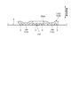
【解決手段】アース端子101、及び、ワイヤハーネスWH1は、線状導体W1が接続される導体接続部106と、それぞれ導体接続部106と接続されて平面状に形成され、接地面3と対向した状態で締結部材1を介して当該接地面3に締結可能である複数の締結部103と、複数の締結部103を連結し締結部103より変形容易である変形部104とを備えることを特徴とする。この結果、アース端子101、及び、ワイヤハーネスWH1は、接地面3に適正に締結することができる、という効果を奏する。
【選択図】図1
Description
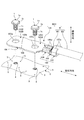
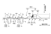
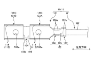
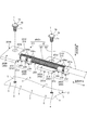
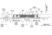
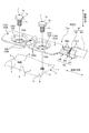
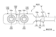
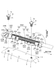
図1は、実施形態1に係るアース端子の概略構成を表す斜視図である。図2は、実施形態1に係るアース端子の概略構成を表す側面図である。図3は、実施形態1に係るアース端子の概略構成を表す平面図(接地面と対向する側の平面図)である。
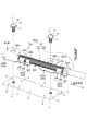
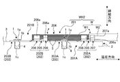
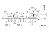
図4は、実施形態2に係るアース端子の概略構成を表す斜視図である。図5は、実施形態2に係るアース端子の概略構成を表す側面図である。図6は、実施形態2に係るアース端子の概略構成を表す平面図(接地面と対向する側の平面図)である。実施形態2に係るアース端子、及び、ワイヤハーネスは、変形部の構成が実施形態1とは異なる。以下では、上述した実施形態と同様の構成要素には共通の符号が付されるとともに、共通する構成、作用、効果については、重複した説明はできるだけ省略する(以下、同様。)。
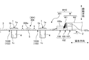
図7は、実施形態3に係るアース端子の概略構成を表す斜視図である。図8は、実施形態3に係るアース端子の概略構成を表す側面図である。図9は、実施形態3に係るアース端子の概略構成を表す平面図(接地面と対向する側の平面図)である。実施形態3に係るアース端子、及び、ワイヤハーネスは、変形部の構成が実施形態1、2とは異なる。
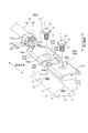
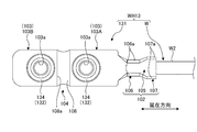
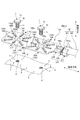
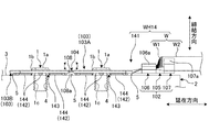
図10は、実施形態4に係るアース端子の概略構成を表す斜視図である。図11は、実施形態4に係るアース端子の概略構成を表す側面図である。図12は、実施形態4に係るアース端子の概略構成を表す平面図(接地面と対向する側の平面図)である。図13は、図10に示すL11−L11断面図である。実施形態4に係るアース端子、及び、ワイヤハーネスは、突出部を備える点で実施形態1とは異なる。なお、図13は、わかり易くするため締結部材の図示を省略している。
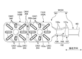
図14は、実施形態5に係るアース端子の概略構成を表す斜視図である。図15は、実施形態5に係るアース端子の概略構成を表す側面図である。図16は、実施形態5に係るアース端子の概略構成を表す平面図(接地面と対向する側の平面図)である。実施形態5に係るアース端子、及び、ワイヤハーネスは、突出部を備える点で実施形態2とは異なる。
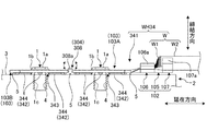
図17は、実施形態6に係るアース端子の概略構成を表す斜視図である。図18は、実施形態6に係るアース端子の概略構成を表す側面図である。図19は、実施形態6に係るアース端子の概略構成を表す平面図(接地面と対向する側の平面図)である。実施形態6に係るアース端子、及び、ワイヤハーネスは、突出部を備える点で実施形態3とは異なる。
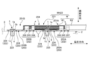
図20は、実施形態7に係るアース端子の概略構成を表す斜視図である。図21は、実施形態7に係るアース端子の概略構成を表す側面図である。図22は、実施形態7に係るアース端子の概略構成を表す平面図(接地面と対向する側の平面図)である。図23は、図20に示すL12−L12断面図である。実施形態7に係るアース端子、及び、ワイヤハーネスは、突出部の構成が実施形態4とは異なる。
図24は、実施形態8に係るアース端子の概略構成を表す斜視図である。図25は、実施形態8に係るアース端子の概略構成を表す側面図である。図26は、実施形態8に係るアース端子の概略構成を表す平面図(接地面と対向する側の平面図)である。実施形態8に係るアース端子、及び、ワイヤハーネスは、突出部の構成が実施形態5とは異なる。
図27は、実施形態9に係るアース端子の概略構成を表す斜視図である。図28は、実施形態9に係るアース端子の概略構成を表す側面図である。図29は、実施形態9に係るアース端子の概略構成を表す平面図(接地面と対向する側の平面図)である。実施形態9に係るアース端子、及び、ワイヤハーネスは、突出部の構成が実施形態6とは異なる。
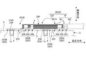
図30は、実施形態10に係るアース端子の概略構成を表す斜視図である。図31は、実施形態10に係るアース端子の概略構成を表す側面図である。図32は、実施形態10に係るアース端子の概略構成を表す平面図(接地面と対向する側の平面図)である。図33は、図30に示すL13−L13断面図である。実施形態10に係るアース端子、及び、ワイヤハーネスは、突出部の構成が実施形態4、7とは異なる。なお、図33は、わかり易くするため締結部材の図示を省略している。
図34は、実施形態11に係るアース端子の概略構成を表す斜視図である。図35は、実施形態11に係るアース端子の概略構成を表す側面図である。図36は、実施形態11に係るアース端子の概略構成を表す平面図(接地面と対向する側の平面図)である。実施形態11に係るアース端子、及び、ワイヤハーネスは、突出部の構成が実施形態5、8とは異なる。
図37は、実施形態12に係るアース端子の概略構成を表す斜視図である。図38は、実施形態12に係るアース端子の概略構成を表す側面図である。図39は、実施形態12に係るアース端子の概略構成を表す平面図(接地面と対向する側の平面図)である。実施形態12に係るアース端子、及び、ワイヤハーネスは、突出部の構成が実施形態6、9とは異なる。
図40は、実施形態13に係るアース端子の概略構成を表す斜視図である。図41は、実施形態13に係るアース端子の概略構成を表す側面図である。図42は、実施形態13に係るアース端子の概略構成を表す平面図(接地面と対向する側の平面図)である。図43は、図20に示すL14−L14断面図である。実施形態13に係るアース端子、及び、ワイヤハーネスは、突出部の構成が実施形態4、7、10とは異なる。なお、図43は、わかり易くするため締結部材の図示を省略している。
図44は、実施形態14に係るアース端子の概略構成を表す斜視図である。図45は、実施形態14に係るアース端子の概略構成を表す側面図である。図46は、実施形態14に係るアース端子の概略構成を表す平面図(接地面と対向する側の平面図)である。実施形態14に係るアース端子、及び、ワイヤハーネスは、突出部の構成が実施形態5、8、11とは異なる。
図47は、実施形態15に係るアース端子の概略構成を表す斜視図である。図48は、実施形態15に係るアース端子の概略構成を表す側面図である。図49は、実施形態15に係るアース端子の概略構成を表す平面図(接地面と対向する側の平面図)である。実施形態15に係るアース端子、及び、ワイヤハーネスは、突出部の構成が実施形態6、9、12とは異なる。
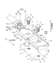
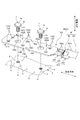
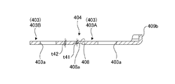
図50、図51、図52は、実施形態16に係るアース端子の概略構成を表す斜視図である。図53は、実施形態16に係るアース端子の概略構成を表す平面図(接地面と対向する側とは反対側の平面図)である。図54は、実施形態16に係るアース端子の概略構成を表す平面図(接地面と対向する側の平面図)である。図55は、図50に示すL15−L15断面図である。実施形態16に係るアース端子、及び、ワイヤハーネスは、締結部の構成が実施形態1等とは異なる。なお、以下の説明では、各図において、図示をわかり易くするため電線を二点鎖線で略記している。また、電線の各構成については、適宜図1等を参照する。
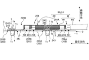
図56、図57は、実施形態17に係るアース端子の概略構成を表す斜視図である。図58は、実施形態17に係るアース端子の概略構成を表す側面図である。図59は、実施形態17に係るアース端子の概略構成を表す平面図(接地面と対向する側の平面図)である。実施形態17に係るアース端子、及び、ワイヤハーネスは、変形部として、第1変形部と第2変形部とを含んで構成される点で実施形態2とは異なる。
3 接地面
5 異物(物体)
101、111、121、131、141、201、211、221、231、241、301、311、321、331、341、401、501 アース端子
103、203、403、503 締結部
104、204、304、404、504 変形部
106、206、406、506 導体接続部
108、408、508 薄肉部
108a、408a、508a 凹部
112、122、132、142、212、222、232、242、312、322、332、342 突出部
113、123、133、143、213、223、233、243、313、323、333、343 異物回避空間部
114、214、314 フランジ部
124、224、324 突部
134、234、334 絞り部
144、244、344 ビード部
308 屈曲連結部
308a 屈曲部
504A 第1変形部
504B 第2変形部
W 電線
W1 線状導体
WH1、WH11、WH12、WH13、WH14、WH2、WH21、WH22、WH23、WH24、WH3、WH31、WH32、WH33、WH34、WH4、WH5 ワイヤハーネス
Claims (10)
- 線状導体が接続される導体接続部と、
それぞれ前記導体接続部と接続されて平面状に形成され、接地面と対向した状態で締結部材を介して当該接地面に締結可能である複数の締結部と、
前記複数の締結部を連結し前記締結部より変形容易である変形部とを備えることを特徴とする、
アース端子。 - 前記変形部は、前記締結部より薄肉に形成される薄肉部を含んで構成される、
請求項1に記載のアース端子。 - 前記薄肉部は、前記接地面と対向する面側に凹部を有する、
請求項2に記載のアース端子。 - 前記導体接続部は、少なくとも前記複数の締結部に対応してそれぞれ1つずつ設けられ、
前記変形部は、前記複数の締結部を、各前記導体接続部を介して連結し前記締結部より可撓性を有する前記線状導体を含む、
請求項1乃至請求項3のいずれか1項に記載のアース端子。 - 前記変形部は、前記複数の締結部を、屈曲部を介して連結する屈曲連結部を含んで構成される、
請求項1乃至請求項4のいずれか1項に記載のアース端子。 - 前記屈曲部は、前記接地面から離間する側に突出して屈曲する、
請求項5に記載のアース端子。 - 前記導体接続部は、少なくとも前記複数の締結部に対応してそれぞれ1つずつ設けられ、
前記変形部は、前記複数の締結部を、各前記導体接続部を介して連結し前記締結部より可撓性を有する前記線状導体を含む第1変形部と、前記第1変形部によって連結された前記複数の締結部を連結し、前記締結部より薄肉に形成される薄肉部を含む第2変形部とを有する、
請求項1乃至請求項6のいずれか1項に記載のアース端子。 - 前記変形部は、前記接地面と対向する位置に設けられる、
請求項1乃至請求項7のいずれか1項に記載のアース端子。 - 前記締結部から突出して形成され前記締結部と前記接地面とが対向する状態で当該接地面と当接し当該締結部と当該接地面との間に前記接地面上の物体を収容可能である異物回避空間部を形成する突出部を備える、
請求項1乃至請求項8のいずれか1項に記載のアース端子。 - 導電性を有する線状の線状導体を含んで構成される電線と、
前記線状導体が接続される導体接続部、それぞれ前記導体接続部と接続されて平面状に形成され、接地面と対向した状態で締結部材を介して当該接地面に締結可能である複数の締結部、及び、前記複数の締結部を連結し前記締結部より変形容易である変形部を有するアース端子とを備えることを特徴とする、
ワイヤハーネス。
Priority Applications (4)
| Application Number | Priority Date | Filing Date | Title |
|---|---|---|---|
| JP2015240442A JP6262191B2 (ja) | 2015-12-09 | 2015-12-09 | アース端子、及び、ワイヤハーネス |
| US15/371,763 US10483665B2 (en) | 2015-12-09 | 2016-12-07 | Ground terminal and wire harness |
| DE102016224416.7A DE102016224416A1 (de) | 2015-12-09 | 2016-12-08 | Erdungs-Anschluss und Kabelbaum |
| CN201611121535.XA CN106941216B (zh) | 2015-12-09 | 2016-12-08 | 接地端子和线束 |
Applications Claiming Priority (1)
| Application Number | Priority Date | Filing Date | Title |
|---|---|---|---|
| JP2015240442A JP6262191B2 (ja) | 2015-12-09 | 2015-12-09 | アース端子、及び、ワイヤハーネス |
Publications (2)
| Publication Number | Publication Date |
|---|---|
| JP2017107728A true JP2017107728A (ja) | 2017-06-15 |
| JP6262191B2 JP6262191B2 (ja) | 2018-01-17 |
Family
ID=58773218
Family Applications (1)
| Application Number | Title | Priority Date | Filing Date |
|---|---|---|---|
| JP2015240442A Active JP6262191B2 (ja) | 2015-12-09 | 2015-12-09 | アース端子、及び、ワイヤハーネス |
Country Status (4)
| Country | Link |
|---|---|
| US (1) | US10483665B2 (ja) |
| JP (1) | JP6262191B2 (ja) |
| CN (1) | CN106941216B (ja) |
| DE (1) | DE102016224416A1 (ja) |
Cited By (2)
| Publication number | Priority date | Publication date | Assignee | Title |
|---|---|---|---|---|
| JP2023168688A (ja) * | 2022-05-16 | 2023-11-29 | 矢崎総業株式会社 | アース端子 |
| JP2024057950A (ja) * | 2022-10-13 | 2024-04-25 | 古河電気工業株式会社 | アルミニウム端子 |
Families Citing this family (11)
| Publication number | Priority date | Publication date | Assignee | Title |
|---|---|---|---|---|
| JP7006338B2 (ja) * | 2018-02-09 | 2022-01-24 | トヨタ自動車株式会社 | 車両のボデーアース構造およびボデーアース経路形成方法 |
| CN109216980B (zh) * | 2018-09-26 | 2023-12-08 | 温州意华接插件股份有限公司 | 高速插座电连接器 |
| DE102018127729A1 (de) * | 2018-11-07 | 2020-05-07 | Auto-Kabel Management Gmbh | Verfahren zur Herstellung eines Anschlussteils für elektrische Anlagen, Anschlussteil sowie Verbindung eines Anschlussteils mit einem Kabel |
| CN110091817B (zh) * | 2019-05-08 | 2025-07-11 | 珠海广通汽车有限公司 | 一种多点集中接地装置以及多点集中接地系统 |
| JP7092729B2 (ja) * | 2019-09-30 | 2022-06-28 | 矢崎総業株式会社 | 端子、及び、端子と被取付面との組付構造 |
| JP7453792B2 (ja) * | 2020-01-16 | 2024-03-21 | 日本航空電子工業株式会社 | 固定具、固定方法、ケーブル組立体及び構造体 |
| DE102020108669B3 (de) * | 2020-03-30 | 2021-04-29 | Auto-Kabel Management Gmbh | Verbindungsanordnung und Verfahren zum Verbinden einer Verbindungsanordnung mit einem Bauteil |
| US11881664B2 (en) | 2020-12-18 | 2024-01-23 | Hamilton Sundstrand Corporation | Power feeder connector devices |
| JP7436430B2 (ja) * | 2021-07-20 | 2024-02-21 | 矢崎総業株式会社 | 端子、端子付電線、及び、接続構造 |
| EP4147939B1 (de) * | 2021-09-14 | 2024-04-03 | ULTIMATE Europe Transportation Equipment GmbH | Verkleidungselement für einen innenraum eines schienenfahrzeuges |
| US20260213432A1 (en) * | 2025-01-21 | 2026-07-23 | GM Global Technology Operations LLC | Ring terminal with integrated anti-rotational third hand mechanism |
Citations (4)
| Publication number | Priority date | Publication date | Assignee | Title |
|---|---|---|---|---|
| JPS5014586U (ja) * | 1973-06-04 | 1975-02-15 | ||
| US4983133A (en) * | 1989-05-31 | 1991-01-08 | Scyoc William C Van | Electrical terminal with annular section |
| JPH0992360A (ja) * | 1995-09-19 | 1997-04-04 | Sumitomo Wiring Syst Ltd | アース端子の取付け構造 |
| US20080182462A1 (en) * | 2007-01-26 | 2008-07-31 | Fci Americas Technology, Inc. | Modifiable electrical connector lug |
Family Cites Families (22)
| Publication number | Priority date | Publication date | Assignee | Title |
|---|---|---|---|---|
| US2406079A (en) * | 1944-01-19 | 1946-08-20 | Fred G Krueger | Washer lug |
| US2748452A (en) * | 1953-05-07 | 1956-06-05 | Aircraft Marine Prod Inc | Methods and blanks for making connectors |
| US3082397A (en) * | 1960-02-04 | 1963-03-19 | Sylvania Electric Prod | Socket |
| US4196960A (en) * | 1976-11-10 | 1980-04-08 | Erico Products, Inc. | Cable lug and method of making same |
| DE3009548A1 (de) * | 1980-03-13 | 1981-09-24 | Ibm Deutschland Gmbh, 7000 Stuttgart | Spurnachlaufsteuerung fuer magnetkoepfe sowie verfahren zur kompensation gleichfoermiger stoergroessen |
| US5558531A (en) * | 1994-02-09 | 1996-09-24 | Yazaki Corporation | Combination terminal |
| JP3167106B2 (ja) * | 1996-04-22 | 2001-05-21 | 住友電装株式会社 | 端子金具の組付け構造 |
| US5688131A (en) * | 1996-09-03 | 1997-11-18 | Wirth Co Engineering, Inc. | Multi-use electrical connector |
| JP3317174B2 (ja) * | 1997-01-23 | 2002-08-26 | 住友電装株式会社 | アースジョイントコネクタ |
| JP3749670B2 (ja) * | 2001-03-13 | 2006-03-01 | 住友電装株式会社 | 組合せ端子金具及び、複数の端子金具の組み付け構造 |
| JP3912106B2 (ja) * | 2001-12-27 | 2007-05-09 | 住友電装株式会社 | アース端子 |
| US7192319B1 (en) * | 2005-11-28 | 2007-03-20 | Cooper Technologies Company | Insulated cable termination assembly and method of fabrication |
| US7467968B1 (en) * | 2007-08-24 | 2008-12-23 | Fci Americas Technology, Inc. | Electrical connector with pad hole locator |
| US7955101B2 (en) * | 2008-10-07 | 2011-06-07 | Hubbell Incorporated | Modifiable electrical connector lug |
| JP5634691B2 (ja) * | 2009-08-18 | 2014-12-03 | 矢崎総業株式会社 | バスバ |
| JP5428674B2 (ja) * | 2009-09-08 | 2014-02-26 | 株式会社オートネットワーク技術研究所 | アース接続装置及びこれを含むワイヤハーネス |
| KR20100120107A (ko) | 2010-10-22 | 2010-11-12 | 오용준 | 강화 터미널 및 그 제조 방법 |
| JP5760971B2 (ja) | 2011-09-20 | 2015-08-12 | 株式会社オートネットワーク技術研究所 | アース接続装置 |
| JP6106517B2 (ja) | 2013-05-09 | 2017-04-05 | 矢崎総業株式会社 | 丸端子固定構造 |
| JP2015103494A (ja) | 2013-11-28 | 2015-06-04 | 住友電装株式会社 | アース端子 |
| JP6249849B2 (ja) * | 2014-03-25 | 2017-12-20 | 矢崎総業株式会社 | アース端子 |
| US9559443B2 (en) * | 2014-11-14 | 2017-01-31 | Hubbell Incorporated | Electrical connectors having field modifiable lugs |
-
2015
- 2015-12-09 JP JP2015240442A patent/JP6262191B2/ja active Active
-
2016
- 2016-12-07 US US15/371,763 patent/US10483665B2/en active Active
- 2016-12-08 CN CN201611121535.XA patent/CN106941216B/zh active Active
- 2016-12-08 DE DE102016224416.7A patent/DE102016224416A1/de active Pending
Patent Citations (4)
| Publication number | Priority date | Publication date | Assignee | Title |
|---|---|---|---|---|
| JPS5014586U (ja) * | 1973-06-04 | 1975-02-15 | ||
| US4983133A (en) * | 1989-05-31 | 1991-01-08 | Scyoc William C Van | Electrical terminal with annular section |
| JPH0992360A (ja) * | 1995-09-19 | 1997-04-04 | Sumitomo Wiring Syst Ltd | アース端子の取付け構造 |
| US20080182462A1 (en) * | 2007-01-26 | 2008-07-31 | Fci Americas Technology, Inc. | Modifiable electrical connector lug |
Cited By (4)
| Publication number | Priority date | Publication date | Assignee | Title |
|---|---|---|---|---|
| JP2023168688A (ja) * | 2022-05-16 | 2023-11-29 | 矢崎総業株式会社 | アース端子 |
| JP7768834B2 (ja) | 2022-05-16 | 2025-11-12 | 矢崎総業株式会社 | アース端子 |
| JP2024057950A (ja) * | 2022-10-13 | 2024-04-25 | 古河電気工業株式会社 | アルミニウム端子 |
| JP7834006B2 (ja) | 2022-10-13 | 2026-03-23 | 古河電気工業株式会社 | アルミニウム端子 |
Also Published As
| Publication number | Publication date |
|---|---|
| DE102016224416A1 (de) | 2017-06-14 |
| US20170170580A1 (en) | 2017-06-15 |
| US10483665B2 (en) | 2019-11-19 |
| JP6262191B2 (ja) | 2018-01-17 |
| CN106941216B (zh) | 2019-06-14 |
| CN106941216A (zh) | 2017-07-11 |
Similar Documents
| Publication | Publication Date | Title |
|---|---|---|
| JP6262191B2 (ja) | アース端子、及び、ワイヤハーネス | |
| US7354297B2 (en) | Connector fixing structure | |
| JP5823787B2 (ja) | 同軸ケーブルとシールド端子との接続構造およびその接続方法 | |
| JP2010165486A (ja) | 電線接続ユニット | |
| US10008784B2 (en) | Terminal fitting fixing structure and wire harness | |
| JP2023021126A (ja) | ワイヤハーネス | |
| JP6159218B2 (ja) | シールドシェル | |
| JP7459809B2 (ja) | ワイヤハーネス | |
| US11881644B2 (en) | Wire reinforcing material at the pont of crimping a terminal onto the wire | |
| CN107732480B (zh) | 线缆连接器组件 | |
| JP2017107730A (ja) | アース端子、及び、ワイヤハーネス | |
| JP2017107729A (ja) | アース端子、及び、ワイヤハーネス | |
| WO2016167107A1 (ja) | 単芯線およびワイヤハーネス | |
| US11588255B2 (en) | Electric wire with terminal having improved anticorrosion performance | |
| JP2004254478A (ja) | 機器用シールドコネクタの接続構造 | |
| JP4503458B2 (ja) | シールド電線のアース接続具およびアース接続方法 | |
| JP7623168B2 (ja) | 外装構造および該外装構造を備えたワイヤーハーネス | |
| WO2014061797A1 (ja) | 接続端子 | |
| JP6556512B2 (ja) | ワイヤハーネス | |
| US12160075B2 (en) | Rotary connector device and flat cable assembly for rotary connector device | |
| JP2019140008A (ja) | ワイヤハーネス | |
| JP7159933B2 (ja) | ワイヤハーネス | |
| WO2023214498A1 (ja) | ワイヤハーネス | |
| CN117134151A (zh) | 带连接器的线缆 | |
| WO2014061798A1 (ja) | 接続端子 |
Legal Events
| Date | Code | Title | Description |
|---|---|---|---|
| A977 | Report on retrieval |
Free format text: JAPANESE INTERMEDIATE CODE: A971007 Effective date: 20170921 |
|
| A131 | Notification of reasons for refusal |
Free format text: JAPANESE INTERMEDIATE CODE: A131 Effective date: 20170926 |
|
| A521 | Request for written amendment filed |
Free format text: JAPANESE INTERMEDIATE CODE: A523 Effective date: 20171102 |
|
| TRDD | Decision of grant or rejection written | ||
| A01 | Written decision to grant a patent or to grant a registration (utility model) |
Free format text: JAPANESE INTERMEDIATE CODE: A01 Effective date: 20171205 |
|
| A61 | First payment of annual fees (during grant procedure) |
Free format text: JAPANESE INTERMEDIATE CODE: A61 Effective date: 20171213 |
|
| R150 | Certificate of patent or registration of utility model |
Ref document number: 6262191 Country of ref document: JP Free format text: JAPANESE INTERMEDIATE CODE: R150 |
|
| R250 | Receipt of annual fees |
Free format text: JAPANESE INTERMEDIATE CODE: R250 |
|
| R250 | Receipt of annual fees |
Free format text: JAPANESE INTERMEDIATE CODE: R250 |
|
| R250 | Receipt of annual fees |
Free format text: JAPANESE INTERMEDIATE CODE: R250 |
|
| S531 | Written request for registration of change of domicile |
Free format text: JAPANESE INTERMEDIATE CODE: R313531 |
|
| R350 | Written notification of registration of transfer |
Free format text: JAPANESE INTERMEDIATE CODE: R350 |
|
| R250 | Receipt of annual fees |
Free format text: JAPANESE INTERMEDIATE CODE: R250 |
|
| R250 | Receipt of annual fees |
Free format text: JAPANESE INTERMEDIATE CODE: R250 |
|
| R250 | Receipt of annual fees |
Free format text: JAPANESE INTERMEDIATE CODE: R250 |