JP2017108020A - Lens unit, led module and lighting apparatus using the same - Google Patents
Lens unit, led module and lighting apparatus using the same Download PDFInfo
- Publication number
- JP2017108020A JP2017108020A JP2015241431A JP2015241431A JP2017108020A JP 2017108020 A JP2017108020 A JP 2017108020A JP 2015241431 A JP2015241431 A JP 2015241431A JP 2015241431 A JP2015241431 A JP 2015241431A JP 2017108020 A JP2017108020 A JP 2017108020A
- Authority
- JP
- Japan
- Prior art keywords
- led
- lens
- lens unit
- light emitting
- light
- Prior art date
- Legal status (The legal status is an assumption and is not a legal conclusion. Google has not performed a legal analysis and makes no representation as to the accuracy of the status listed.)
- Pending
Links
Images




Classifications
-
- F—MECHANICAL ENGINEERING; LIGHTING; HEATING; WEAPONS; BLASTING
- F21—LIGHTING
- F21V—FUNCTIONAL FEATURES OR DETAILS OF LIGHTING DEVICES OR SYSTEMS THEREOF; STRUCTURAL COMBINATIONS OF LIGHTING DEVICES WITH OTHER ARTICLES, NOT OTHERWISE PROVIDED FOR
- F21V5/00—Refractors for light sources
- F21V5/007—Array of lenses or refractors for a cluster of light sources, e.g. for arrangement of multiple light sources in one plane
-
- F—MECHANICAL ENGINEERING; LIGHTING; HEATING; WEAPONS; BLASTING
- F21—LIGHTING
- F21K—NON-ELECTRIC LIGHT SOURCES USING LUMINESCENCE; LIGHT SOURCES USING ELECTROCHEMILUMINESCENCE; LIGHT SOURCES USING CHARGES OF COMBUSTIBLE MATERIAL; LIGHT SOURCES USING SEMICONDUCTOR DEVICES AS LIGHT-GENERATING ELEMENTS; LIGHT SOURCES NOT OTHERWISE PROVIDED FOR
- F21K9/00—Light sources using semiconductor devices as light-generating elements, e.g. using light-emitting diodes [LED] or lasers
- F21K9/60—Optical arrangements integrated in the light source, e.g. for improving the colour rendering index or the light extraction
- F21K9/66—Details of globes or covers forming part of the light source
-
- F—MECHANICAL ENGINEERING; LIGHTING; HEATING; WEAPONS; BLASTING
- F21—LIGHTING
- F21V—FUNCTIONAL FEATURES OR DETAILS OF LIGHTING DEVICES OR SYSTEMS THEREOF; STRUCTURAL COMBINATIONS OF LIGHTING DEVICES WITH OTHER ARTICLES, NOT OTHERWISE PROVIDED FOR
- F21V17/00—Fastening of component parts of lighting devices, e.g. shades, globes, refractors, reflectors, filters, screens, grids or protective cages
- F21V17/04—Fastening of component parts of lighting devices, e.g. shades, globes, refractors, reflectors, filters, screens, grids or protective cages the fastening being onto or by the light source
-
- F—MECHANICAL ENGINEERING; LIGHTING; HEATING; WEAPONS; BLASTING
- F21—LIGHTING
- F21V—FUNCTIONAL FEATURES OR DETAILS OF LIGHTING DEVICES OR SYSTEMS THEREOF; STRUCTURAL COMBINATIONS OF LIGHTING DEVICES WITH OTHER ARTICLES, NOT OTHERWISE PROVIDED FOR
- F21V17/00—Fastening of component parts of lighting devices, e.g. shades, globes, refractors, reflectors, filters, screens, grids or protective cages
- F21V17/10—Fastening of component parts of lighting devices, e.g. shades, globes, refractors, reflectors, filters, screens, grids or protective cages characterised by specific fastening means or way of fastening
-
- F—MECHANICAL ENGINEERING; LIGHTING; HEATING; WEAPONS; BLASTING
- F21—LIGHTING
- F21V—FUNCTIONAL FEATURES OR DETAILS OF LIGHTING DEVICES OR SYSTEMS THEREOF; STRUCTURAL COMBINATIONS OF LIGHTING DEVICES WITH OTHER ARTICLES, NOT OTHERWISE PROVIDED FOR
- F21V17/00—Fastening of component parts of lighting devices, e.g. shades, globes, refractors, reflectors, filters, screens, grids or protective cages
- F21V17/10—Fastening of component parts of lighting devices, e.g. shades, globes, refractors, reflectors, filters, screens, grids or protective cages characterised by specific fastening means or way of fastening
- F21V17/12—Fastening of component parts of lighting devices, e.g. shades, globes, refractors, reflectors, filters, screens, grids or protective cages characterised by specific fastening means or way of fastening by screwing
-
- F—MECHANICAL ENGINEERING; LIGHTING; HEATING; WEAPONS; BLASTING
- F21—LIGHTING
- F21V—FUNCTIONAL FEATURES OR DETAILS OF LIGHTING DEVICES OR SYSTEMS THEREOF; STRUCTURAL COMBINATIONS OF LIGHTING DEVICES WITH OTHER ARTICLES, NOT OTHERWISE PROVIDED FOR
- F21V21/00—Supporting, suspending, or attaching arrangements for lighting devices; Hand grips
- F21V21/14—Adjustable mountings
- F21V21/26—Pivoted arms
-
- F—MECHANICAL ENGINEERING; LIGHTING; HEATING; WEAPONS; BLASTING
- F21—LIGHTING
- F21V—FUNCTIONAL FEATURES OR DETAILS OF LIGHTING DEVICES OR SYSTEMS THEREOF; STRUCTURAL COMBINATIONS OF LIGHTING DEVICES WITH OTHER ARTICLES, NOT OTHERWISE PROVIDED FOR
- F21V21/00—Supporting, suspending, or attaching arrangements for lighting devices; Hand grips
- F21V21/14—Adjustable mountings
- F21V21/30—Pivoted housings or frames
-
- F—MECHANICAL ENGINEERING; LIGHTING; HEATING; WEAPONS; BLASTING
- F21—LIGHTING
- F21V—FUNCTIONAL FEATURES OR DETAILS OF LIGHTING DEVICES OR SYSTEMS THEREOF; STRUCTURAL COMBINATIONS OF LIGHTING DEVICES WITH OTHER ARTICLES, NOT OTHERWISE PROVIDED FOR
- F21V23/00—Arrangement of electric circuit elements in or on lighting devices
- F21V23/001—Arrangement of electric circuit elements in or on lighting devices the elements being electrical wires or cables
- F21V23/002—Arrangements of cables or conductors inside a lighting device, e.g. means for guiding along parts of the housing or in a pivoting arm
-
- F—MECHANICAL ENGINEERING; LIGHTING; HEATING; WEAPONS; BLASTING
- F21—LIGHTING
- F21V—FUNCTIONAL FEATURES OR DETAILS OF LIGHTING DEVICES OR SYSTEMS THEREOF; STRUCTURAL COMBINATIONS OF LIGHTING DEVICES WITH OTHER ARTICLES, NOT OTHERWISE PROVIDED FOR
- F21V23/00—Arrangement of electric circuit elements in or on lighting devices
- F21V23/02—Arrangement of electric circuit elements in or on lighting devices the elements being transformers, impedances or power supply units, e.g. a transformer with a rectifier
-
- F—MECHANICAL ENGINEERING; LIGHTING; HEATING; WEAPONS; BLASTING
- F21—LIGHTING
- F21V—FUNCTIONAL FEATURES OR DETAILS OF LIGHTING DEVICES OR SYSTEMS THEREOF; STRUCTURAL COMBINATIONS OF LIGHTING DEVICES WITH OTHER ARTICLES, NOT OTHERWISE PROVIDED FOR
- F21V29/00—Protecting lighting devices from thermal damage; Cooling or heating arrangements specially adapted for lighting devices or systems
- F21V29/50—Cooling arrangements
- F21V29/70—Cooling arrangements characterised by passive heat-dissipating elements, e.g. heat-sinks
- F21V29/74—Cooling arrangements characterised by passive heat-dissipating elements, e.g. heat-sinks with fins or blades
- F21V29/76—Cooling arrangements characterised by passive heat-dissipating elements, e.g. heat-sinks with fins or blades with essentially identical parallel planar fins or blades, e.g. with comb-like cross-section
- F21V29/763—Cooling arrangements characterised by passive heat-dissipating elements, e.g. heat-sinks with fins or blades with essentially identical parallel planar fins or blades, e.g. with comb-like cross-section the planes containing the fins or blades having the direction of the light emitting axis
-
- F—MECHANICAL ENGINEERING; LIGHTING; HEATING; WEAPONS; BLASTING
- F21—LIGHTING
- F21V—FUNCTIONAL FEATURES OR DETAILS OF LIGHTING DEVICES OR SYSTEMS THEREOF; STRUCTURAL COMBINATIONS OF LIGHTING DEVICES WITH OTHER ARTICLES, NOT OTHERWISE PROVIDED FOR
- F21V3/00—Globes; Bowls; Cover glasses
- F21V3/02—Globes; Bowls; Cover glasses characterised by the shape
-
- H—ELECTRICITY
- H10—SEMICONDUCTOR DEVICES; ELECTRIC SOLID-STATE DEVICES NOT OTHERWISE PROVIDED FOR
- H10H—INORGANIC LIGHT-EMITTING SEMICONDUCTOR DEVICES HAVING POTENTIAL BARRIERS
- H10H20/00—Individual inorganic light-emitting semiconductor devices having potential barriers, e.g. light-emitting diodes [LED]
- H10H20/80—Constructional details
- H10H20/85—Packages
- H10H20/8506—Containers
-
- H—ELECTRICITY
- H10—SEMICONDUCTOR DEVICES; ELECTRIC SOLID-STATE DEVICES NOT OTHERWISE PROVIDED FOR
- H10W—GENERIC PACKAGES, INTERCONNECTIONS, CONNECTORS OR OTHER CONSTRUCTIONAL DETAILS OF DEVICES COVERED BY CLASS H10
- H10W90/00—Package configurations
-
- F—MECHANICAL ENGINEERING; LIGHTING; HEATING; WEAPONS; BLASTING
- F21—LIGHTING
- F21Y—INDEXING SCHEME ASSOCIATED WITH SUBCLASSES F21K, F21L, F21S and F21V, RELATING TO THE FORM OR THE KIND OF THE LIGHT SOURCES OR OF THE COLOUR OF THE LIGHT EMITTED
- F21Y2105/00—Planar light sources
- F21Y2105/10—Planar light sources comprising a two-dimensional [2D] array of point-like light-generating elements
- F21Y2105/12—Planar light sources comprising a two-dimensional [2D] array of point-like light-generating elements characterised by the geometrical disposition of the light-generating elements, e.g. arranging light-generating elements in differing patterns or densities
-
- F—MECHANICAL ENGINEERING; LIGHTING; HEATING; WEAPONS; BLASTING
- F21—LIGHTING
- F21Y—INDEXING SCHEME ASSOCIATED WITH SUBCLASSES F21K, F21L, F21S and F21V, RELATING TO THE FORM OR THE KIND OF THE LIGHT SOURCES OR OF THE COLOUR OF THE LIGHT EMITTED
- F21Y2113/00—Combination of light sources
- F21Y2113/10—Combination of light sources of different colours
- F21Y2113/13—Combination of light sources of different colours comprising an assembly of point-like light sources
-
- F—MECHANICAL ENGINEERING; LIGHTING; HEATING; WEAPONS; BLASTING
- F21—LIGHTING
- F21Y—INDEXING SCHEME ASSOCIATED WITH SUBCLASSES F21K, F21L, F21S and F21V, RELATING TO THE FORM OR THE KIND OF THE LIGHT SOURCES OR OF THE COLOUR OF THE LIGHT EMITTED
- F21Y2115/00—Light-generating elements of semiconductor light sources
- F21Y2115/10—Light-emitting diodes [LED]
-
- H—ELECTRICITY
- H10—SEMICONDUCTOR DEVICES; ELECTRIC SOLID-STATE DEVICES NOT OTHERWISE PROVIDED FOR
- H10H—INORGANIC LIGHT-EMITTING SEMICONDUCTOR DEVICES HAVING POTENTIAL BARRIERS
- H10H20/00—Individual inorganic light-emitting semiconductor devices having potential barriers, e.g. light-emitting diodes [LED]
- H10H20/80—Constructional details
- H10H20/85—Packages
- H10H20/852—Encapsulations
- H10H20/853—Encapsulations characterised by their shape
Landscapes
- Engineering & Computer Science (AREA)
- General Engineering & Computer Science (AREA)
- Power Engineering (AREA)
- Physics & Mathematics (AREA)
- Microelectronics & Electronic Packaging (AREA)
- Optics & Photonics (AREA)
- Non-Portable Lighting Devices Or Systems Thereof (AREA)
- Led Device Packages (AREA)
Abstract
【課題】より被照射面での色ムラを低減した光を放射させることができるレンズユニット、LEDモジュールおよびそれを用いた照明器具を提供する。【解決手段】レンズユニットは、複数のレンズ部1tと、複数のレンズ部1tを保持する本体部と、を備えている。複数のレンズ部1tは、発光色の異なるLED21と一対一に対応して備えられている。レンズ部1tそれぞれは、発光色の異なるLED21におけるLEDチップ21aの発光面21aaからの距離が等しくなるように本体部に保持されている。【選択図】図5A lens unit, an LED module, and a lighting fixture using the same that can emit light with reduced color unevenness on a surface to be irradiated are provided. The lens unit includes a plurality of lens portions and a main body that holds the plurality of lens portions. The plurality of lens portions 1t are provided in one-to-one correspondence with the LEDs 21 having different emission colors. Each of the lens portions 1t is held by the main body portion so that the distances from the light emitting surface 21aa of the LED chip 21a in the LEDs 21 having different emission colors are equal. [Selection] Figure 5
Description
本発明は、レンズユニット、LEDモジュールおよびそれを用いた照明器具に関する。 The present invention relates to a lens unit, an LED module, and a lighting fixture using the same.
近年、LED(light emitting diode)を光源とする照明器具が用いられている。 In recent years, lighting fixtures using LEDs (light emitting diodes) as light sources have been used.
この種の照明器具としては、基板上にアレイ状に配置された複数の単位光源を有する構成が知られている(たとえば、特許文献1を参照)。 As this type of lighting fixture, a configuration having a plurality of unit light sources arranged in an array on a substrate is known (see, for example, Patent Document 1).
特許文献1では、単位光源は、チップ状のLED素子が光学樹脂レンズによりドーム状に覆われたLEDの構造に形成されている。特許文献1は、光学樹脂レンズの高さが異なる複数種類の単位光源を所定のパターンで配置することによって、所定の配光を得ることができる、としている。特許文献1では、発光色の異なるLEDごとに光学樹脂レンズの高さを異ならせることは開示されていない。
In
ところで、照明器具では、発光色が異なる複数のLEDを用いて混色光を放射させる場合、より被照射面での色ムラを低減した光を放射させることが求められており、単純に特許文献1を利用した構成だけでは十分ではなく、更なる改良が求められている。 By the way, in a lighting fixture, when emitting mixed color light using a plurality of LEDs having different emission colors, it is required to emit light with reduced color unevenness on the irradiated surface. The configuration using only is not sufficient, and further improvement is required.
本発明の目的は、より被照射面での色ムラを低減した光を放射させることができるレンズユニット、LEDモジュールおよびそれを用いた照明器具を提供することにある。 The objective of this invention is providing the lens unit which can radiate | emit the light which reduced the color nonuniformity in a to-be-irradiated surface, an LED module, and a lighting fixture using the same.
本発明のレンズユニットは、複数のレンズ部と、本体部と、を備えている。上記本体部は、上記複数のレンズ部を保持することができるように構成されている。上記複数のレンズ部は、発光色の異なるLEDと一対一に対応して備えられている。上記レンズ部それぞれは、上記発光色の異なるLEDにおけるLEDチップの発光面からの距離が等しくなるように上記本体部に保持されていることを特徴とする。 The lens unit of the present invention includes a plurality of lens portions and a main body portion. The main body portion is configured to hold the plurality of lens portions. The plurality of lens portions are provided in one-to-one correspondence with LEDs having different emission colors. Each of the lens portions is held by the main body portion so that the distances from the light emitting surface of the LED chip in the LEDs having different emission colors are equal.
本発明のLEDモジュールは、複数のLEDと、実装基板と、レンズユニットと、を備えている。上記実装基板は、上記複数のLEDが実装面に実装される。上記レンズユニットは、上記実装基板を覆うように設けられる。上記複数のLEDは、第1のLEDと、第2のLEDと、を少なくとも備えている。上記第2のLEDは、上記第1のLEDの発光色と異なる発光色の光を放射する。上記第1のLEDは、発光層を備えた第1のLEDチップを有している。上記第2のLEDは、発光層を備えた第2のLEDチップを有している。上記第1のLEDチップと上記第2のLEDチップとは、上記実装面から上記発光層における発光面までの高さが異なっている。上記レンズユニットは、複数のレンズ部と、本体部と、を備えている。上記本体部は、上記複数のレンズ部を保持することができるように構成されている。上記複数のレンズ部は、第1レンズ部と、第2レンズ部と、を少なくとも備えている。上記第1レンズ部は、上記第1のLEDと対応して設けられている。上記第2レンズ部は、上第2のLEDと対応して設けられている。上記第1レンズ部と上記第2レンズ部とは、第1距離と第2距離との差が、第1間隔と第2間隔との差よりも小さくなるように設けられていることを特徴とする。上記第1距離とは、上記第1のLEDにおける発光面から上記第1レンズ部までの距離である。上記第2距離とは、上記第2のLEDにおける発光面から上記第2レンズ部までの距離である。上記第1間隔は、上記実装面から上記第1レンズ部までの間隔である。上記第2間隔は、上記実装面から上記第2レンズ部までの間隔である。 The LED module of the present invention includes a plurality of LEDs, a mounting substrate, and a lens unit. The mounting board has the plurality of LEDs mounted on a mounting surface. The lens unit is provided so as to cover the mounting substrate. The plurality of LEDs include at least a first LED and a second LED. The second LED emits light of an emission color different from the emission color of the first LED. The first LED has a first LED chip provided with a light emitting layer. The second LED has a second LED chip having a light emitting layer. The first LED chip and the second LED chip have different heights from the mounting surface to the light emitting surface of the light emitting layer. The lens unit includes a plurality of lens portions and a main body portion. The main body portion is configured to hold the plurality of lens portions. The plurality of lens units include at least a first lens unit and a second lens unit. The first lens portion is provided corresponding to the first LED. The second lens portion is provided corresponding to the upper second LED. The first lens unit and the second lens unit are provided such that a difference between the first distance and the second distance is smaller than a difference between the first interval and the second interval. To do. The first distance is a distance from the light emitting surface of the first LED to the first lens unit. The second distance is a distance from the light emitting surface of the second LED to the second lens unit. The first interval is an interval from the mounting surface to the first lens unit. The second interval is an interval from the mounting surface to the second lens unit.
本発明の照明器具は、上述の前記LEDモジュールと、当該LEDモジュールを保持する器具本体と、を備えたことを特徴とする。 The lighting fixture of the present invention includes the LED module described above and a fixture main body that holds the LED module.
本発明のレンズユニットは、より被照射面での色ムラを低減した光を放射させることができる。 The lens unit of the present invention can emit light with reduced color unevenness on the irradiated surface.
本発明のLEDモジュールは、より被照射面での色ムラを低減した光を放射させることができるレンズユニットを備えた構成とすることができる。 The LED module of the present invention can be configured to include a lens unit that can emit light with reduced color unevenness on the irradiated surface.
本発明の照明器具は、より被照射面での色ムラを低減した光を放射させることができるLEDモジュールを備えた構成とすることができる。 The lighting fixture of this invention can be set as the structure provided with the LED module which can radiate | emit the light which reduced the color nonuniformity in a to-be-irradiated surface more.
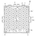
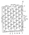
以下では、本実施形態のレンズユニット10について、図1ないし図5を参照して説明し、図1、図5および図6を参照してLEDモジュール20を説明し、図7および図8を参照して照明器具30を説明する。図中において、同じ部材に対しては、同じ符号を付して重複する説明を省略する。各図面が示す部材の大きさや位置関係は、説明を明確にするために誇張していることがある。以下の説明において、本実施形態を構成する各要素は、複数の要素を一の部材で構成して一の部材で複数の要素を兼用する態様としてもよいし、一の部材の機能を複数の部材で分担して実現してもよい。
Hereinafter, the
本実施形態におけるLEDモジュール20は、図1および図6に示すように、複数のLED21と、実装基板22と、レンズユニット10と、を備えている。実装基板22は、複数のLED21が実装面22aaに実装される。レンズユニット10は、実装基板22を覆うように設けられる。複数のLED21は、第1のLED21mと、第2のLED21nと、を少なくとも備えている。第2のLED21nは、第1のLED21mの発光色と異なる発光色の光を放射する。
As shown in FIGS. 1 and 6, the
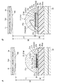
第1のLED21mは、図5Aに示すように、発光層21gを備えた第1のLEDチップ21sを有している。第2のLED21nは、図5Bに示すように、発光層21gを備えた第2のLEDチップ21tを有している。第1のLEDチップ21sと第2のLEDチップ21tとは、実装面22aaから発光層21gにおける発光面21aaまでの高さが異なっている。図5Aでは、第1のLEDチップ21sにおいて、実装面22aaから発光層21gにおける発光面21aaまでの高さを距離H1で例示している。図5Bでは、第2のLEDチップ21tにおいて、実装面22aaから発光層21gにおける発光面21aaまでの高さを距離H2で例示している。
As shown in FIG. 5A, the
レンズユニット10は、複数のレンズ部1tと、本体部2と、を備えている。本体部2は、複数のレンズ部1tを保持することができるように構成されている。複数のレンズ部1tは、第1レンズ部1mと、第2レンズ部1nと、を少なくとも備えている。第1レンズ部1mは、第1のLED21mと対応して設けられている。第2レンズ部1nは、第2のLED21nと対応して設けられている。第1レンズ部1mと第2レンズ部1nとは、第1距離L1と第2距離L2との差が、第1間隔D1と第2間隔D2との差よりも小さくなるように設けられている。第1距離L1は、第1のLED21mにおける発光面21aaから第1レンズ部1mまでの距離である。第2距離L2は、第2のLED21nにおける発光面21aaから第2レンズ部1nまでの距離である。第1間隔D1は、実装面22aaから第1レンズ部1mまでの間隔である。第2間隔D2は、実装面22aaから第2レンズ部1nまでの間隔である。
The
実施形態におけるLEDモジュール20では、第1レンズ部1mと第2レンズ部1nとは、第1距離L1と第2距離L2との差が、第1間隔D1と第2間隔D2との差よりも、小さくなるように設けられることで、より被照射面での色ムラを低減した光を放射できる。
In the
以下では、本実施形態のレンズユニット10が用いられるLEDモジュール20および照明器具30について、より詳細に説明する。LEDモジュール20は、照明器具30の光源を構成している。照明器具30は、建物のライトアップなどで使用される投光器を構成している。
Below, the
LEDモジュール20は、さらに、図6に示すように、レンズユニット10とLED21と実装基板22とに加え、放熱部材23と、遮光シート24と、カバーブロック25と、ケーブルグランド27と、を備えている。
As shown in FIG. 6, the
レンズユニット10は、透光性を有している。レンズユニット10は、図1ないし図4に示すように、レンズ部1tと本体部2とに加え、レンズ枠1sと、固定片3と、支持部4と、を備えている。
The
レンズ部1tは、レンズ枠1sを介して、本体部2に保持されている。レンズ枠1sとレンズ部1tとは、LED21からの光を所定の配光特性が得られるようにするレンズ体1を構成している。レンズ体1は、LED21に向かって突出する回転放物体形状をしている。レンズ体1は、回転放物体形状の仮想の回転軸1xxに沿って、本体部2の外平面2aaに沿った外出面1abから円柱状に窪んだ第1凹所1ccを有している。レンズ体1は、回転軸1xxに沿って、回転放物体形状の先端部が窪んだ第2凹所1cdを有している。レンズ部1tは、回転軸1xxに沿った断面視において、第1凹所1ccの内底面と対向し、第1凹所1ccと反対側が凸状に突出している。レンズ部1tは、第1凹所1ccの内底面が光出射面1ceを構成している。レンズ部1tは、第2凹所1cdの内底面が光入射面1aaを構成している。レンズ部1tは、第1凹所1ccの光出射面1ceと、凸部の光入射面1aaとの間で、平凸レンズを構成している。レンズ枠1sは、回転軸1xx周りにレンズ部1tの外周に沿って設けられている。
The
レンズ体1は、LED21が第2凹所1cdに収容できるように、レンズ枠1sとレンズ部1tとが形成されている。レンズ部1tは、LED21から放射された光を光入射面1aaで受けて、光出射面1ceから放射できるように構成されている。レンズ体1では、LED21から放射されレンズ部1tに入射された光の一部が、レンズ枠1sの放物曲面1afで反射され、外出面1ab側から放射できるように構成されている。
The
複数のレンズ体1は、異なる発光色のLED21に対応して、回転軸1xxに沿った第1凹所1ccの深さが異なるように形成されている。複数のレンズ体1は、回転軸1xxに沿った外出面1abから回転放物体形状の先端部までが異なるように形成されている。複数のレンズ体1は、回転軸1xxに沿った第2凹所1cdの深さが同じとなるように形成されている。複数のレンズ部1tそれぞれは、回転軸1xxに沿った平凸レンズにおける光入射面1aaと光出射面1ceとの間の厚みが同じになるように形成されている。
The plurality of
本体部2は、底板2aと、周壁2bと、を有している。底板2aは、矩形平板状の外形形状をしている。周壁2bは、底板2aの外周縁に沿って、底板2aの厚み方向に突出して設けられている。底板2aには、実装基板22に実装された複数のLED21と一対一に対応するように、複数のレンズ部1tが2次元アレイ状に設けられている。固定片3は、周壁2bの端縁から突出するように構成されている。固定片3は、側面視において、L字状の外形形状をしている。固定片3は、図2に示すように、平面視において、矩形の底板2aにおける一辺に沿って、1つ設けられている。周壁2bには、平面視において、3つの固定片3が設けられている。固定片3は、平面視において、外部に向かって開口するC字形状の開口部3ccが中央部に形成されている。支持部4は、矩形状の本体部2における四隅に設けられている。支持部4は、実装基板22を覆うように底板2aを配置させ、周壁2bと実装基板22との間に隙間ができるように形成されている。
The
レンズユニット10は、レンズ部1tとレンズ枠1sと本体部2と固定片3と支持部4とが一体的に形成されている。レンズユニット10の材料は、たとえば、アクリル樹脂などの合成樹脂材料を用いることができる。レンズユニット10は、たとえば、射出成形により形成することができる。レンズユニット10は、レンズ体1と本体部2とが別体に形成され、レンズ体1が本体部2に取り付けられるように構成されてもよい。
In the
LED21それぞれは、図5Aおよび図5Bに示すように、LEDチップ21aと、基体21bと、封止材21cと、接続部材21dと、を備えている。図5Aでは、第1のLED21mの構造を例示しており、図5Bでは、第2のLED21nの構造を例示している。以下では、最初に、第1のLED21mと第2のLED21nとに共通する構成について説明する。
As shown in FIGS. 5A and 5B, each
LEDチップ21aは、基板21eと、第1導電型半導体層21fと、発光層21gと、第2導電型半導体層21hと、を備えている。第1導電型半導体層21fは、基板21e上に設けられている。第1導電型半導体層21fは、たとえば、n型半導体材料により形成される。発光層21gは、第1導電型半導体層21fにおける基板21eとは反対側に設けられている。第2導電型半導体層21hは、発光層21gにおける第1導電型半導体層21fと反対側に設けられている。第2導電型半導体層21hは、たとえば、p型半導体材料により形成される。
The
LEDチップ21aは、半導体発光素子であり、半導体のエピタキシャル成長や熱拡散などを行うことで製造される。発光層21gは、たとえば、InGaN、AlInGaN、AlInGaPやGaAsPなどの半導体材料によって形成されている。
The
基体21bは、矩形平板状の外形形状をしている。基体21bには、LEDチップ21aが実装されている。基体21bの表面には、リード端子21kが設けられている。リード端子21kは、LEDチップ21aに給電できるように構成されている。基体21bは、セラミック基板が用いられている。基体21bは、セラミック基板だけに限られず、樹脂基板であってもよい。
The
封止材21cは、LEDチップ21aを覆って封止できるように、基体21bに設けられている。封止材21cは、凸レンズを構成している。封止材21cの材料としては、シリコーン樹脂が用いられている。封止材21cの材料としては、シリコーン樹脂だけに限られず、エポキシ樹脂、アクリル樹脂やガラスなどが用いられてもよい。LED21は、凸レンズが設けられていることで、LEDチップ21aからの光を外部に効率よく取り出すことができる。すなわち、凸レンズは、LEDチップ21aからの光が直接的に照射される1次レンズを構成し、レンズユニット10のレンズ体1は、LED21における凸レンズから放射された光の配光制御を行う2次レンズを構成している。
The sealing
接続部材21dは、基体21bに設けられたリード端子21kと、LEDチップ21aとを電気的に接続する。接続部材21dとしては、たとえば、金属バンプ21d1、導電性樹脂21d2、金属ワイヤ21d3などが挙げられる。金属バンプ21d1としては、半田バンプやボールバンプを用いることができる。導電性樹脂21d2としては、Agペーストなどを用いて形成することができる。金属ワイヤ21d3としては、金線やアルミニウム線などを用いることができる。
The connecting
LED21のうち、第1のLED21mは、複数の金属バンプ21d1により基体21bへの実装と電気的接続とが行われている。第1のLED21mでは、図5Aに示すように、金属バンプ21d1を介して、LEDチップ21aにおける第1導電型半導体層21fと、基体21bに設けられた一対のリード端子21kのうちの一方と、が電気的に接続されている。第1のLED21mでは、金属バンプ21d1を介して、LEDチップ21aにおける第2導電型半導体層21hと、基体21bに設けられた一対のリード端子21kのうちの他方と、が電気的に接続されている。第1のLED21mでは、LEDチップ21aにおける基板21eが透光性の絶縁材により形成されている。
Among the
LED21のうち、第2のLED21nでは、図5Bに示すように、導電性樹脂21d2により、LEDチップ21aにおける導電性の基板21eと、基体21bに設けられた一対のリード端子21kのうちの一方と、が電気的に接続されている。第2のLED21nでは、金属ワイヤ21d3を介して、LEDチップ21aにおける第2導電型半導体層21hと、基体21bに設けられた一対のリード端子21kのうちの他方と、が電気的に接続されている。
Among the
実装基板22は、図6に示すように、矩形状の平板の外形形状をしている。実装基板22は、矩形状だけに限られず、円形状でも、楕円形状の外形形状に形成されていてもよい。実装基板22は、実装面22aaにおいて、複数個のLED21が2次元アレイ状に配置されている。実装基板22は、レセプタクルコネクタ26が実装面22aaに実装されている。レセプタクルコネクタ26は、実装基板22に形成された配線用の導体を介して、複数のLED21と電気的に接続される。実装基板22は、金属ベースプリント配線板を用いて形成されている。実装基板22は、金属ベースプリント配線板だけに限らず、たとえば、セラミック基板やガラスエポキシ樹脂基板などであってもよい。
As shown in FIG. 6, the mounting
放熱部材23は、図1、図6、図7および図8に示すように、ベース部23aと、複数枚の放熱板23bと、縁部23cと、を備えている。ベース部23aは、長尺の矩形平板状の外形形状をしている。ベース部23aは、実装基板22が搭載される第1面23aaに複数の第1ねじ孔23ceが設けられている。第1ねじ孔23ceには、雌ねじが形成されている。ベース部23aは、厚み方向に貫通する第1挿通孔23chが設けられている。第1挿通孔23chは、長手方向の中央部において、ベース部23aの短手方向の一端側に設けられている。第1挿通孔23chには、ケーブルグランド27が取り付けられる。ベース部23aには、ケーブルグランド27を介して、LED21へ電力を給電する給電線が挿通される。
As shown in FIGS. 1, 6, 7, and 8, the
放熱板23bは、ベース部23aの第1面23aaと反対の第2面23abから突出している。放熱板23bは、矩形の平板状に形成されている。複数枚の放熱板23bは、所定の間隔でベース部23aに設けられている。複数枚の放熱板23bは、等間隔でベース部23aに配置されていてもよいし、隣接する放熱板23bが異なる間隔で配置されていてもよい。放熱板23bは、実装基板22が搭載されたベース部23aにおける第2面23ab側からLED21の発する熱を効率よく放熱させることができる。
The
縁部23cは、直方体状の外形形状をしている。縁部23cは、平面視が長方形のベース部23aにおける長辺に沿って設けられている。縁部23cは、ベース部23aに2個設けられている。2個の縁部23cは、ベース部23aを介して、対向するように配置されている。縁部23cは、ベース部23aの厚み方向において、ベース部23aの厚み寸法よりも大きい寸法で形成されている。縁部23cは、ベース部23aの厚み方向に沿って、カバーブロック25と結合される第1結合部23caを備えている。第1結合部23caは、第2ねじ孔により構成されている。第2ねじ孔には、雌ねじが形成されている。第1結合部23caは、縁部23cの長手方向に沿って並ぶように複数設けられている。
The
縁部23cは、ベース部23aの厚み方向と直交する縁部23cの長手方向に沿って、他の部材に結合できる第2結合部23cbを備えていることが好ましい。第2結合部23cbは、第3ねじ孔により構成されている。第3ねじ孔には、雌ねじが形成されている。第2結合部23cbは、縁部23cの長手方向の両端面にそれぞれ1つずつ設けられている。縁部23cには、ベース部23aの厚み方向と縁部23cの長手方向とに直交する方向に沿って、第3結合部23ccが設けられている。第3結合部23ccは、縁部23cと他の部材との結合に利用することができるように形成されている。第3結合部23ccは、縁部23cを貫通する第4ねじ孔で構成されている。第4ねじ孔には、雌ねじが形成されている。第3結合部23ccは、縁部23cの長手方向に沿って、所定の間隔を空けて複数設けられている。
It is preferable that the
放熱部材23は、金属材料により、ベース部23aと放熱板23bと縁部23cとが一体的に形成されている。放熱部材23の材料としては、たとえば、アルミニウム合金や銅合金などの熱伝導性に優れた金属材料を用いることができる。
In the
遮光シート24は、矩形平板状の外形形状をしている。遮光シート24は、レンズユニット10に収容できるように、本体部2よりも若干小さく形成されている。遮光シート24には、厚み方向に貫通する複数の孔部24aaが設けられている。孔部24aaには、レンズユニット10のレンズ体1におけるレンズ枠1sが挿入できるように形成されている。遮光シート24は、レンズ枠1sの放物曲面1afから外部に漏れ出た光を吸収することで、レンズ部1tで配光制御できなかった光が被照射面側において筋状に照射されることを抑制することができる。遮光シート24は、カーボンが含有された樹脂材料により形成することができる。遮光シート24は、樹脂材料にカーボンが含有されることで、黒色に着色されている。
The
カバーブロック25は、図6に示すように、カバー25aと、第1押板25bと、第1スペーサ25cと、第2押板25dと、第2スペーサ25eと、シール部材25fと、を備えている。カバー25aは、カバー本体25a1と、外鍔25a2と、を有している。カバー本体25a1は、有底角筒状の外形形状をしている。外鍔25a2は、平面視において、矩形の環状の外形形状をしている。外鍔25a2は、カバー本体25a1の端縁から外方に突出するように形成されている。外鍔25a2の四隅には、円形の嵌合孔25caが設けられている。外鍔25a2では、長手方向に沿って、複数の第2挿通孔25cbが所定の間隔を空けて設けられている。外鍔25a2では、短手方向に沿って、複数の第3挿通孔25ccが所定の間隔を空けて設けられている。図6では、3つの第3挿通孔25ccと、4つの第2挿通孔25cbと、が図示されている。カバー本体25a1と外鍔25a2とは、一体的に形成されている。カバー25aは、透光性を有している。カバー25aの材料は、たとえば、ポリカーボネート樹脂などの合成樹脂材料を用いることができる。
As shown in FIG. 6, the
第1押板25bは、長尺に形成されており、外鍔25a2における長手方向よりも若干短い長さに形成されている。第1押板25bは、第1主片25b1と、第1側片25b2と、第1端片25b3と、を有している。第1主片25b1は、長尺の板状の外形形状をしている。第1主片25b1は、厚み方向に貫通する第4挿通孔25cdが長手方向の両端部と中央部側に設けられている。第1側片25b2は、第1主片25b1の長手方向に沿った一端縁から第1主片25b1と直交する向きに延びるように設けられている。第1端片25b3は、第1主片25b1の長手方向に沿った一端縁と反対の他端縁から第1主片25b1と直交する向きに延びるように設けられている。第1端片25b3は、第1主片25b1を介して、第1側片25b2と反対側に配置されている。第1押板25bは、第1主片25b1と第1側片25b2と第1端片25b3とが、一体的に形成されている。第1押板25bは、金属板の打ち抜き加工および折り曲げ加工を施すことにより形成されている。第1押板25bの材料としては、たとえば、ステンレスなどの金属材料を用いることができる。
The first
第1スペーサ25cは、長尺の板状の外形形状をしている。第1スペーサ25cは、第1押板25bの第1主片25b1よりも若干小さい形状に形成されている。第1スペーサ25cは、第1主片25b1と外鍔25a2との間に挟まれるように構成されている。第1スペーサ25cは、厚み方向に貫通され、第1押板25bの第4挿通孔25cdに対応して連なるように設けられた第1貫通孔25ceを有している。
The
第2押板25dは、長尺に形成されており、外鍔25a2における短手方向よりも若干短い長さに形成されている。第2押板25dは、第2主片25d1と、第2側片25d2と、第2端片25d3と、を有している。第2主片25d1は、長尺の板状の外形形状をしている。第2主片25d1は、第5挿通孔25deが設けられている。第2側片25d2は、第2主片25d1の長手方向に沿った一端縁から第2主片25d1と直交する向きに延びている。第2端片25d3は、第2主片25d1の長手方向に沿った一端縁と反対の他端縁から第2主片25d1と直交する向きに延びている。第2端片25d3は、第2主片25d1を介して、第2側片25d2と反対側に突出している。第2押板25dは、第2主片25d1と第2側片25d2と第2端片25d3とが、一体的に形成されている。第2押板25dは、金属板の打ち抜き加工および折り曲げ加工を施すことにより形成されている。第2押板25dの材料としては、たとえば、ステンレスなどの金属材料を用いることができる。
The second
第2スペーサ25eは、長尺の板状の外形形状をしている。第2スペーサ25eは、第2押板25dの第2主片25d1よりも若干小さい形状に形成されている。第2スペーサ25eは、第2主片25d1と外鍔25a2との間に挟まれるように構成されている。第2スペーサ25eは、厚み方向に貫通され、第2押板25dの第5挿通孔25deに対応して連なるように設けられた第2貫通孔25eeを有している。
The
シール部材25fは、矩形の枠状の外形形状に形成されている。シール部材25fは、カバー25aにおける外鍔25a2と同等の大きさに形成されている。シール部材25fは、突起25f1が四隅に設けられている。突起25f1は、カバー25aの嵌合孔25caに嵌め合すことができるように形成されている。シール部材25fは、厚み方向に貫通する第6挿通孔25fcを備えている。第6挿通孔25fcは、シール部材25fの各辺に沿って複数設けられている。シール部材25fは、たとえば、シリコーン樹脂により形成することができる。
The
ケーブルグランド27は、ケーブルグランド本体27aと、キャップ27bと、取付ねじ27cと、を備えている。キャップ27bは、ケーブルグランド本体27aを覆うことができるように構成されている。取付ねじ27cは、ケーブルグランド本体27aおよびキャップ27bを、ベース部23aに取り付ける。ケーブルグランド27は、挿入された給電線を締め付けることができるように構成されている。
The
以下では、本実施形態におけるLEDモジュール20において、より被照射面での色ムラを低減した光を放射させることができることについて説明する。
Below, in the
本実施形態におけるLEDモジュール20では、LED21として、赤色光を放射する赤色LEDと、緑色光を放射する緑色LEDと、青色光を放射する青色LEDとが用いられている。LEDモジュール20では、赤色LEDからの赤色光と、緑色LEDからの緑色光と、青色LEDからの青色光とを混色させて、白色光を放射させることができる。
In the
LED21におけるLEDチップ21aでは、放射する光エネルギに対応したバンドギャップの半導体材料により、発光層21gが形成されている。赤色LEDでは、たとえば、ピーク発光波長が620nmの赤色光を発光させるため、発光層21gの材料にAlInGaPが用いられている。緑色LEDでは、たとえば、ピーク発光波長が525nmの緑色光を発光させるため、発光層21gの材料にInGaNが用いられている。青色LEDでは、たとえば、ピーク発光波長が475nmの青色光を発光させるため、緑色LEDの発光層21gよりもInの含有量が少ないInGaNが用いられている。
In the
ところで、LEDチップ21aは、一般に有機金属化学気相成長法(MOCVD法)などにより形成されており、発光層21gの半導体材料が異なれば、LEDチップ21aの基板21eや半導体の積層構造などが異なる。LEDチップ21aでは、発光層21gの半導体材料の違いに起因して、LEDチップ21aの厚み方向における発光面21aaの位置が異なる場合がある。ここでは、LEDチップ21aにおいて、レンズ部1tと対向しレンズ部1tに向けて光を放射する発光層21gの面側を、発光面21aaと称している。
By the way, the
青色LEDチップや緑色LEDチップでは、発光層21gの材料にInGaNが用いられ、図5Aに示す第1のLED21mの構造に形成されている。赤色LEDチップは、発光層21gの材料にAlInGaPが用いられ、図5Bに示す第2のLED21nの構造に形成されている。
In the blue LED chip and the green LED chip, InGaN is used as the material of the
また、LED21では、様々な用途に使用されるため、LEDチップ21aから放射させる光を効率よく外部に放射させるレンズの外形寸法が、LEDチップ21aが発光する光色に係わらず、同様の外形形状に形成される傾向にある。LED21では、発光色が異なれば、放射される光の配向特性が異なる場合がある。LEDモジュール20では、実装基板22の実装面22aaから赤色LEDにおける発光面21aaまでの距離H2が、実装基板22の実装面22aaから緑色LEDもしくは青色LEDにおける発光面21aaまでの距離H1よりも長い。
In addition, since the
そのため、LEDモジュールでは、赤色LEDと緑色LEDと青色LEDとを用いて混色光を得る場合、実装面からレンズ部までの距離が全て等しければ、発光面の位置の違いに起因して、被照射面に照射された混色光に色ムラが生ずるおそれがある。 Therefore, in the LED module, when mixed color light is obtained using a red LED, a green LED, and a blue LED, if all the distances from the mounting surface to the lens unit are equal, due to the difference in the position of the light emitting surface, There is a possibility that color unevenness occurs in the mixed color light irradiated on the surface.
本実施形態のレンズユニット10は、LED21における発光面21aaからレンズ部1tまでの高さを異ならせて、第1距離L1と第2距離L2との差が、第1間隔D1と第2間隔D2との差よりも小さくなるようにしている。本実施形態のレンズユニット10では、第1距離L1と第2距離L2との距離の差が小さいことが好ましく、差がない場合でもよい。
In the
言い換えれば、本実施形態のレンズユニット10は、図1ないし図4に示すように、複数のレンズ部1tと、本体部2と、を備えている。本体部2は、複数のレンズ部1tを保持することができるように構成されている。複数のレンズ部1tは、発光色の異なるLED21と一対一に対応して備えられている。レンズ部1tそれぞれは、発光色の異なるLED21におけるLEDチップ21aの発光面21aaからの距離が等しくなるように本体部2に保持されている。
In other words, the
実施形態のレンズユニット10では、レンズ部1tそれぞれが、発光色の異なるLED21におけるLEDチップ21aの発光面21aaからの距離が等しくなるように本体部2に保持されることで、より被照射面での色ムラを低減した光を放射させることができる。
In the
次に、LEDモジュール20を組み立てる組立工程について、説明する。
Next, an assembly process for assembling the
LEDモジュール20の組立工程では、放熱部材23におけるベース部23aの第1面23aa上に、予めLED21が実装された実装基板22が載せ置かれる。組立工程では、先端にプラグコネクタが設けられた給電線を、ケーブルグランド27を介して、ベース部23aの第1挿通孔23chに挿通させる。組立工程では、レンズユニット10が遮光シート24を介して実装基板22に被せられる。LEDモジュール20では、LED21が、レンズユニット10のレンズ部1tと、一対一に対応するように配置される。
In the assembly process of the
次に、組立工程では、ケーブルグランド27に挿通された給電線の先端に設けられたプラグコネクタが、レセプタクルコネクタ26に接続される。組立工程では、レンズユニット10の支持部4が、放熱部材23の第1面23aaに載せ置かれ、レンズユニット10の周壁2bと実装基板22との間に設けられた隙間を介して、レンズユニット10の外に給電線が引き廻されるように配置させる。レンズユニット10は、固定片3がベース部23aにねじ止めされる。組立工程では、固定片3のねじ止めに伴ってレンズユニット10に歪みが生じない程度に、ねじ締めのトルクが設定されている。
Next, in the assembly process, the plug connector provided at the tip of the power supply line inserted through the
次に、組立工程では、カバーブロック25がベース部23aに取り付けられる。カバーブロック25では、シール部材25fの突起25f1を、カバー25aの嵌合孔25caに嵌め合わせられて、シール部材25fがカバー25aに取り付けられる。組立工程では、シール部材25fが取り付けられたカバー25aが、レンズユニット10を覆うように放熱部材23に配置される。組立工程では、第1スペーサ25cを介して、第1押板25bをカバー25aの外鍔25a2に重ねて配置させる。第1押板25bと第1スペーサ25cとカバー25aとは、第1押板25bの第4挿通孔25cdと、第1スペーサ25cの第1貫通孔25ceと、カバー25aの第2挿通孔25cbと、が一致するように配置される。カバーブロック25は、第1押板25bの第4挿通孔25cdと、第1スペーサ25cの第1貫通孔25ceと、カバー25aの第2挿通孔25cbと、シール部材25fの第6挿通孔25fcと、に第2ねじ25gが挿通される。
Next, in the assembly process, the
組立工程では、第2スペーサ25eを介して、第2押板25dをカバー25aの外鍔25a2と重ねて配置させる。第2押板25dと第2スペーサ25eとカバー25aとは、第2押板25dの第5挿通孔25deと、第2スペーサ25eの第2貫通孔25eeと、カバー25aの第3挿通孔25ccとが一致するように配置される。
In the assembling process, the second
カバーブロック25は、第2押板25dの第5挿通孔25deと、第2スペーサ25eの第2貫通孔25eeと、カバー25aの第3挿通孔25ccと、シール部材25fの第6挿通孔25fcと、に第2ねじ25gが挿通される。第2ねじ25gは、ベース部23aにおける第1結合部23caの第2ねじ孔にねじ込みされる。カバーブロック25は、第2ねじ25gにより、放熱部材23に固定される。
The
次に、本実施形態における照明器具30について、図7および図8を参照して説明する。
Next, the
照明器具30は、LEDモジュール20と、器具本体31と、を備えている。器具本体31は、LEDモジュール20を保持することができるように構成されている。
The
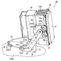
照明器具30は、LEDモジュール20を1つ備えている。器具本体31は、保持部32と、配線ボックス34と、ワイヤ35と、ワイヤ受け36と、を備えている。保持部32は、アーム32aと、アーム取付部材32bと、連結部材32cと、を備えている。アーム32aは、一対のアーム取付部材32bを介して、LEDモジュール20を保持することができるように構成されている。
The
アーム32aは、固定板32a1と、立ち上げ片32a2と、支持片32a3と、を備えている。アーム32aは、LEDモジュール20を設置面50aaに対して所定の角度で保持できる構成とされている。固定板32a1は、平板状の外形形状をしている。固定板32a1は、設置面50aaに固定させるために用いられる。固定板32a1は、図8に示すように、中心部に円形の固定孔32aaが貫通されている。固定板32a1は、固定孔32aaを中心とする半円弧状の長孔32ccが設けられている。固定板32a1は、固定孔32aaに挿通される第2ボルトと、長孔32ccに挿通される第3ボルトとで固定板32a1が設置面50aaとなる投光器台などに固定される。立ち上げ片32a2は、固定板32a1の端部から立ち上がるように設けられている。立ち上がり片32a2は、固定板32a1を介して、対向するように、一対設けられている。支持片32a3は、固定板32a1から立ち上がる立ち上がり片32a2の先端から延びるように設けられている。
The
アーム32aは、固定板32a1と立ち上げ片32a2と支持片32a3とが一体的に形成されている。アーム32aの材料としては、たとえば、ステンレスなどの金属材料が用いられる。アーム32aは、金属板の打ち抜き加工および折り曲げ加工を施すことにより形成される。アーム32aは、固定板32a1の長孔32ccに挿通される第3ボルトを緩めることで、アーム32aに保持されたLEDモジュール20の向きを、水平方向に沿って適宜に変更させることができるように構成されている。
In the
アーム取付部材32bは、固定部32b1と、取付部32b2と、軸受部32b3と、を有している。固定部32b1は、底壁32bsと、一対の側壁32btと、を有している。底壁32bsは、矩形平板状に形成されている。一対の側壁32btは、底壁32bsの長手方向に沿って、底壁32bsの短手方向の端縁から底壁32bsの厚み方向に突出するように形成されている。側壁32btは、矩形平板状の外形形状に形成されている。固定部32b1は、底壁32bsと、一対の側壁32btとにより、角樋状の外形形状に形成されている。固定部32b1は、LEDモジュール20における縁部23cと嵌め合すことができるように構成されている。アーム取付部材32bは、固定部32b1を放熱部材23の縁部23cに嵌め合わせて取り付けられている。
The
一対の取付部32b2は、固定部32b1に設けられている。取付部32b2は、円錐台形状の外形形状をしている。取付部32b2は、底壁32bsの厚み方向に沿って、突出するように形成されている。取付部32b2の先端部には、雌ねじが形成されている。一対のアーム取付部材32bうち、一方のアーム取付部材32bには、目盛板32b5を有している。目盛板32b5は、図7に示すように、扇形の平板に形成されている。目盛板32b5には、設置面50aaに対するLEDモジュール20の角度を示すことができるように、目盛りが刻印されている。目盛板32b5は、一方のアーム取付部材32bにおける軸受部32b3の先端部に連結されている。
The pair of attachment portions 32b2 are provided on the fixed portion 32b1. The attachment portion 32b2 has a frustoconical outer shape. The attachment portion 32b2 is formed so as to protrude along the thickness direction of the bottom wall 32bs. A female screw is formed at the tip of the attachment portion 32b2. Of the pair of
軸受部32b3は、円筒状の外形形状をしている。軸受部32b3は、一対の取付部32b2の間に配置されている。軸受部32b3は、取付部32b2と、固定部32b1とを繋げるように構成されている。 The bearing portion 32b3 has a cylindrical outer shape. The bearing portion 32b3 is disposed between the pair of attachment portions 32b2. The bearing portion 32b3 is configured to connect the attachment portion 32b2 and the fixed portion 32b1.
連結部材32cは、長尺の板状の外形形状をしている。連結部材32cは、第1ボルト32b4により、取付部32b2に取り付けられている。連結部材32cは、配線ボックス34を保持できるように構成されている。連結部材32cの材料としては、たとえば、ステンレスなどの金属材料を用いることができる。
The connecting
アーム取付部材32bは、固定部32b1と取付部32b2と軸受部32b3とが一体的に形成されている。固定部32b1と取付部32b2と軸受部32b3とは、たとえば、アルミダイカストによって形成されている。
The
配線ボックス34は、矩形箱状の外形形状に形成されている。配線ボックス34は、内部に中継用の端子台が収納されている。配線ボックス34では、外から引き込まれる電源ケーブルと、LEDモジュール20の給電線と、を端子台により結線できるように構成されている。電源ケーブルは、配線ボックス34の外に設置された電源装置と接続される。照明器具30は、電源装置から配線ボックス34の端子台を介してLEDモジュール20に電力が供給される。照明器具30は、配線ボックス34の外に電源装置を設置する構造だけには限られず、配線ボックス34の内部に電源装置を収納するように構成する構造でもよい。配線ボックス34の材料としては、たとえば、ステンレスなどの金属材料を用いることができる。
The
照明器具30では、支持片32a3に挿通した第4ボルト32a5が、アーム取付部材32bの軸受部32b3にねじ込まれる。照明器具30では、第4ボルト32a5が軸受部32b3に固定されることで、LEDモジュール20を保持部32で回転可能に保持することができる。照明器具30では、アーム取付部材32bに設けられた目盛板32b5により、第4ボルト32a5を中心として、設置面50aaに対するLEDモジュール20の角度を表示することができる。照明器具30は、図7に示すレバー37を回転させることで、設置面50aaに対してLEDモジュール20を所定の角度に変えることができるように構成されている。
In the
本実施形態の照明器具30では、投光器台の設置面50aaに設置される場合、図7および図8に示すように、ワイヤ35の両端をアーム取付部材32bにねじ止めされている。ワイヤ35は、設置面50aaに固定したワイヤ受け36に支持される。照明器具30では、アーム32aが設置面50aaから外れた場合でも、ワイヤ35がアーム32aを支持することで照明器具30の落下が防止される。
In the
以下では、本実施形態の照明器具30における組立工程について簡単に説明する。
Below, the assembly process in the
照明器具30の組立工程では、アーム取付部材32bの固定部32b1と、LEDモジュール20における放熱部材23の縁部23cとが嵌め合わせられる。照明器具30の組立工程では、固定部32b1と、放熱部材23の縁部23cとがねじ止めされる。照明器具30では、第5ボルト32b6が、固定部32b1の側壁32btを介して、縁部23cの第3結合部23ccにねじ止めされる。
In the assembly process of the
次に、照明器具30の組立工程では、第1ボルト32b4により、連結部材32cと、アーム取付部材32bにおける取付部32b2とが固定される。続いて、照明器具30の組立工程では、連結部材32cに配線ボックス34が取り付けられる。照明器具30では、配線ボックス34が連結部材32cに取り付けられた後、アーム取付部材32bの取付部32b2に連結部材32cを取り付けるようにして組み立てられても構わない。照明器具30の組立工程では、配線ボックス34を連結部材32cに取り付けた後、電源ケーブルや給電線の結線作業が行われる。最後に、照明器具30の組立工程では、支持片32a3に挿通した第4ボルト32a5を、アーム取付部材32bの軸受部32b3に設けられている第5ねじ孔にねじ込むことで、アーム32aとアーム取付部材32bとが取り付けられる。
Next, in the assembly process of the
D1 第1間隔
D2 第2間隔
L1 第1距離
L2 第2距離
1t レンズ部
1m 第1レンズ部
1n 第2レンズ部
2 本体部
10 レンズユニット
20 LEDモジュール
21 LED
21a LEDチップ
21aa 発光面
21g 発光層
21m 第1のLED
21n 第2のLED
21s 第1のLEDチップ
21t 第2のLEDチップ
22 実装基板
22aa 実装面
30 照明器具
31 器具本体
D1 1st space | interval D2 2nd space | interval L1 1st distance L2
21a LED chip 21aa
21n second LED
21s
Claims (3)
前記複数のレンズ部は、発光色の異なるLEDと一対一に対応して備えられており、
前記レンズ部それぞれは、前記発光色の異なるLEDにおけるLEDチップの発光面からの距離が等しくなるように前記本体部に保持されていることを特徴とするレンズユニット。 A plurality of lens units, and a main body unit holding the plurality of lens units,
The plurality of lens portions are provided in one-to-one correspondence with LEDs having different emission colors,
Each of the lens units is held by the main body unit so that the distances from the light emitting surface of the LED chip in the LEDs having different emission colors are equal.
前記複数のLEDは、第1のLEDと、該第1のLEDの発光色と異なる発光色の光を放射する第2のLEDとを少なくとも備えており、
前記第1のLEDは、発光層を備えた第1のLEDチップを有し、前記第2のLEDは、発光層を備えた第2のLEDチップを有しており、前記第1のLEDチップと前記第2のLEDチップとは、前記実装面から前記発光層における発光面までの高さが異なっており、
前記レンズユニットは、複数のレンズ部と、該複数のレンズ部を保持する本体部と、を備えており、
前記複数のレンズ部は、第1レンズ部と、第2レンズ部と、を少なくとも備え、
前記第1レンズ部は、第1のLEDと対応して設けられ、第2レンズ部は、前記第2のLEDと対応して設けられており、
前記第1レンズ部と前記第2レンズ部とは、前記第1のLEDにおける発光面から前記第1レンズ部までの第1距離と、前記第2のLEDにおける発光面から前記第2レンズ部までの第2距離との差が、前記実装面から前記第1レンズ部までの第1間隔と、前記実装面から前記第2レンズ部までの第2間隔との差よりも小さくなるように設けられていることを特徴とするLEDモジュール。 A plurality of LEDs, a mounting substrate on which the plurality of LEDs are mounted on a mounting surface, and a lens unit provided so as to cover the mounting substrate,
The plurality of LEDs include at least a first LED and a second LED that emits light of an emission color different from the emission color of the first LED,
The first LED has a first LED chip having a light emitting layer, and the second LED has a second LED chip having a light emitting layer, and the first LED chip. And the second LED chip are different in height from the mounting surface to the light emitting surface in the light emitting layer,
The lens unit includes a plurality of lens units and a main body unit that holds the plurality of lens units,
The plurality of lens units include at least a first lens unit and a second lens unit,
The first lens unit is provided corresponding to the first LED, and the second lens unit is provided corresponding to the second LED,
The first lens unit and the second lens unit are a first distance from a light emitting surface of the first LED to the first lens unit, and from a light emitting surface of the second LED to the second lens unit. The difference between the second distance and the second distance is smaller than the difference between the first distance from the mounting surface to the first lens portion and the second distance from the mounting surface to the second lens portion. The LED module characterized by the above-mentioned.
Priority Applications (3)
| Application Number | Priority Date | Filing Date | Title |
|---|---|---|---|
| JP2015241431A JP2017108020A (en) | 2015-12-10 | 2015-12-10 | Lens unit, led module and lighting apparatus using the same |
| DE102016123839.2A DE102016123839A1 (en) | 2015-12-10 | 2016-12-08 | Lens unit, LED module with the lens unit and lighting fixture with the LED module |
| US15/374,019 US20170167668A1 (en) | 2015-12-10 | 2016-12-09 | Lens unit, led module with the lens unit, and light fixture with the led module |
Applications Claiming Priority (1)
| Application Number | Priority Date | Filing Date | Title |
|---|---|---|---|
| JP2015241431A JP2017108020A (en) | 2015-12-10 | 2015-12-10 | Lens unit, led module and lighting apparatus using the same |
Publications (1)
| Publication Number | Publication Date |
|---|---|
| JP2017108020A true JP2017108020A (en) | 2017-06-15 |
Family
ID=58773310
Family Applications (1)
| Application Number | Title | Priority Date | Filing Date |
|---|---|---|---|
| JP2015241431A Pending JP2017108020A (en) | 2015-12-10 | 2015-12-10 | Lens unit, led module and lighting apparatus using the same |
Country Status (3)
| Country | Link |
|---|---|
| US (1) | US20170167668A1 (en) |
| JP (1) | JP2017108020A (en) |
| DE (1) | DE102016123839A1 (en) |
Cited By (4)
| Publication number | Priority date | Publication date | Assignee | Title |
|---|---|---|---|---|
| JP2019133754A (en) * | 2018-01-29 | 2019-08-08 | 三菱電機株式会社 | Lighting fixture |
| JP2019160578A (en) * | 2018-03-13 | 2019-09-19 | パナソニックIpマネジメント株式会社 | Lighting fixture |
| CN112956021A (en) * | 2018-10-22 | 2021-06-11 | 艾利迪公司 | Optoelectronic device with improved light extraction comprising light emitting diodes |
| WO2024225175A1 (en) * | 2023-04-27 | 2024-10-31 | パナソニックIpマネジメント株式会社 | Lighting fixture |
Families Citing this family (4)
| Publication number | Priority date | Publication date | Assignee | Title |
|---|---|---|---|---|
| CN210717380U (en) * | 2019-11-08 | 2020-06-09 | 欧普照明股份有限公司 | Lens and light source module |
| CN111050452B (en) * | 2019-12-06 | 2021-11-30 | 广州星迪智能光电科技有限公司 | Color temperature consistency matching method |
| US11118748B1 (en) * | 2020-10-26 | 2021-09-14 | Diode Dynamics, LLC | Reflector-less single lens vehicle lamp |
| US20260085813A1 (en) * | 2022-12-16 | 2026-03-26 | Lumileds Llc | Non uniform led placement in rgb multi-optics |
Citations (7)
| Publication number | Priority date | Publication date | Assignee | Title |
|---|---|---|---|---|
| JPH09326509A (en) * | 1996-06-04 | 1997-12-16 | Mitsubishi Cable Ind Ltd | Multicolor light emitting led module |
| US6570324B1 (en) * | 2000-07-19 | 2003-05-27 | Eastman Kodak Company | Image display device with array of lens-lets |
| JP2006086469A (en) * | 2004-09-17 | 2006-03-30 | Matsushita Electric Ind Co Ltd | Semiconductor light emitting device, illumination module, illumination device, and method for manufacturing semiconductor light emitting device |
| JP2008218089A (en) * | 2007-03-01 | 2008-09-18 | Mitsubishi Electric Corp | Lighting device |
| CN101852345A (en) * | 2009-03-30 | 2010-10-06 | 奇力光电科技股份有限公司 | LED light source module |
| JP2013183042A (en) * | 2012-03-02 | 2013-09-12 | Stanley Electric Co Ltd | Light source device |
| US20160265738A1 (en) * | 2013-03-20 | 2016-09-15 | Zumtobel Lighting Gmbh | Assembly for emitting light having an led, a circuit board, and an optical element |
Family Cites Families (7)
| Publication number | Priority date | Publication date | Assignee | Title |
|---|---|---|---|---|
| US7918583B2 (en) * | 2006-08-16 | 2011-04-05 | Rpc Photonics, Inc. | Illumination devices |
| CN101680620B (en) * | 2007-10-23 | 2013-05-01 | Lsi工业公司 | Optics holding and positioning equipment and lighting assemblies |
| JP4879218B2 (en) * | 2008-04-25 | 2012-02-22 | シャープ株式会社 | Lens body, light source unit, and illumination device |
| JP2011204397A (en) | 2010-03-24 | 2011-10-13 | Sony Corp | Lighting system |
| WO2012055046A1 (en) * | 2010-10-27 | 2012-05-03 | Dbm Reflex Enterprises Inc. | Lens array assembly for solid state light sources and method |
| US9435495B2 (en) * | 2011-07-14 | 2016-09-06 | Vitrulux Liability Company | Light-emitting diode lamp |
| RU2670177C2 (en) * | 2011-12-13 | 2018-10-18 | Филипс Лайтинг Холдинг Б.В. | Optical collimator for led lights |
-
2015
- 2015-12-10 JP JP2015241431A patent/JP2017108020A/en active Pending
-
2016
- 2016-12-08 DE DE102016123839.2A patent/DE102016123839A1/en not_active Withdrawn
- 2016-12-09 US US15/374,019 patent/US20170167668A1/en not_active Abandoned
Patent Citations (7)
| Publication number | Priority date | Publication date | Assignee | Title |
|---|---|---|---|---|
| JPH09326509A (en) * | 1996-06-04 | 1997-12-16 | Mitsubishi Cable Ind Ltd | Multicolor light emitting led module |
| US6570324B1 (en) * | 2000-07-19 | 2003-05-27 | Eastman Kodak Company | Image display device with array of lens-lets |
| JP2006086469A (en) * | 2004-09-17 | 2006-03-30 | Matsushita Electric Ind Co Ltd | Semiconductor light emitting device, illumination module, illumination device, and method for manufacturing semiconductor light emitting device |
| JP2008218089A (en) * | 2007-03-01 | 2008-09-18 | Mitsubishi Electric Corp | Lighting device |
| CN101852345A (en) * | 2009-03-30 | 2010-10-06 | 奇力光电科技股份有限公司 | LED light source module |
| JP2013183042A (en) * | 2012-03-02 | 2013-09-12 | Stanley Electric Co Ltd | Light source device |
| US20160265738A1 (en) * | 2013-03-20 | 2016-09-15 | Zumtobel Lighting Gmbh | Assembly for emitting light having an led, a circuit board, and an optical element |
Cited By (11)
| Publication number | Priority date | Publication date | Assignee | Title |
|---|---|---|---|---|
| JP2019133754A (en) * | 2018-01-29 | 2019-08-08 | 三菱電機株式会社 | Lighting fixture |
| JP7080651B2 (en) | 2018-01-29 | 2022-06-06 | 三菱電機株式会社 | lighting equipment |
| JP2022105678A (en) * | 2018-01-29 | 2022-07-14 | 三菱電機株式会社 | lighting equipment |
| JP7422808B2 (en) | 2018-01-29 | 2024-01-26 | 三菱電機株式会社 | lighting equipment |
| JP2019160578A (en) * | 2018-03-13 | 2019-09-19 | パナソニックIpマネジメント株式会社 | Lighting fixture |
| JP7133783B2 (en) | 2018-03-13 | 2022-09-09 | パナソニックIpマネジメント株式会社 | lighting equipment |
| CN112956021A (en) * | 2018-10-22 | 2021-06-11 | 艾利迪公司 | Optoelectronic device with improved light extraction comprising light emitting diodes |
| JP2022505613A (en) * | 2018-10-22 | 2022-01-14 | アルディア | Optoelectronic device with light emitting diode with enhanced light extraction |
| JP7449584B2 (en) | 2018-10-22 | 2024-03-14 | アルディア | Optoelectronic devices with light emitting diodes with enhanced light extraction |
| CN112956021B (en) * | 2018-10-22 | 2024-06-04 | 艾利迪公司 | Optoelectronic device with improved light extraction comprising light emitting diodes |
| WO2024225175A1 (en) * | 2023-04-27 | 2024-10-31 | パナソニックIpマネジメント株式会社 | Lighting fixture |
Also Published As
| Publication number | Publication date |
|---|---|
| DE102016123839A1 (en) | 2017-06-14 |
| US20170167668A1 (en) | 2017-06-15 |
Similar Documents
| Publication | Publication Date | Title |
|---|---|---|
| JP2017108020A (en) | Lens unit, led module and lighting apparatus using the same | |
| JP5459623B2 (en) | Lighting device | |
| US8760042B2 (en) | Lighting device having a through-hole and a groove portion formed in the thermally conductive main body | |
| US8540408B2 (en) | Lamp light source with improved heat dissipation | |
| JP5899449B2 (en) | Illumination light source and illumination device | |
| JP2010141171A (en) | Light-emitting module, and illumination apparatus | |
| JP2012181969A (en) | Bulb type light-emitting element lamp, and lighting fixture | |
| JP2015079718A (en) | Light emitting device, light source for lighting, and lighting device | |
| JP2011204655A (en) | Lighting fixture | |
| JP2012182192A (en) | LED unit and lighting apparatus using the same | |
| JP2012109478A (en) | Light-emitting body and luminaire | |
| JP2011216313A (en) | Luminaire | |
| JP2015215971A (en) | Led unit and lighting device using the same | |
| JP2012023078A (en) | Light emitting device and lighting system | |
| WO2012063842A1 (en) | Illuminating device | |
| CN206310252U (en) | Lens unit, light-emitting diode (LED) module and ligthing paraphernalia | |
| JP2016058223A (en) | Light source unit, illumination lamp, and illumination device | |
| CN205859797U (en) | Ligthing paraphernalia | |
| JP7262073B2 (en) | lighting equipment | |
| JP6032555B2 (en) | Lighting device | |
| JP2019133840A (en) | Lighting device | |
| JP6979628B2 (en) | Mounting structure of light source board | |
| JP5799218B2 (en) | LED unit and lighting apparatus using the same | |
| KR101174259B1 (en) | Lighting apparatus | |
| KR101039653B1 (en) | Lighting device |
Legal Events
| Date | Code | Title | Description |
|---|---|---|---|
| RD02 | Notification of acceptance of power of attorney |
Free format text: JAPANESE INTERMEDIATE CODE: A7422 Effective date: 20170127 |
|
| A621 | Written request for application examination |
Free format text: JAPANESE INTERMEDIATE CODE: A621 Effective date: 20180926 |
|
| A977 | Report on retrieval |
Free format text: JAPANESE INTERMEDIATE CODE: A971007 Effective date: 20190724 |
|
| A131 | Notification of reasons for refusal |
Free format text: JAPANESE INTERMEDIATE CODE: A131 Effective date: 20190730 |
|
| A521 | Request for written amendment filed |
Free format text: JAPANESE INTERMEDIATE CODE: A523 Effective date: 20190930 |
|
| A02 | Decision of refusal |
Free format text: JAPANESE INTERMEDIATE CODE: A02 Effective date: 20200303 |