JP2017113123A - Balloon catheter for duodenal papilla dilatation - Google Patents
Balloon catheter for duodenal papilla dilatation Download PDFInfo
- Publication number
- JP2017113123A JP2017113123A JP2015249493A JP2015249493A JP2017113123A JP 2017113123 A JP2017113123 A JP 2017113123A JP 2015249493 A JP2015249493 A JP 2015249493A JP 2015249493 A JP2015249493 A JP 2015249493A JP 2017113123 A JP2017113123 A JP 2017113123A
- Authority
- JP
- Japan
- Prior art keywords
- balloon
- marker
- catheter
- tube
- distal end
- Prior art date
- Legal status (The legal status is an assumption and is not a legal conclusion. Google has not performed a legal analysis and makes no representation as to the accuracy of the status listed.)
- Pending
Links
Images

Landscapes
- Media Introduction/Drainage Providing Device (AREA)
Abstract
Description
本発明は、十二指腸乳頭拡張用バルーンカテーテルに関する。 The present invention relates to a balloon catheter for expanding the duodenal papilla.
胆管内に生じた結石(胆石)を体外に取り出して除去する総胆管結石治療を行う際、胆石を砕いたり、又は取り出したりする前に、総胆管への入口である十二指腸乳頭(乳頭)を拡張する内視鏡的乳頭バルーン拡張術(EPBD)又は内視鏡的乳頭ラージバルーン拡張術(EPLBD)を行う場合がある。特に、乳頭にある乳頭括約筋の切開術を行わず、又は乳頭括約筋の小切開を行った後に、バルーンカテーテルによる十二指腸乳頭拡張術を行う総胆管結石治療は、低侵襲で感染症を引き起こすことが少ない内視鏡治療方法として注目されている。 When the bile duct stone treatment that removes and removes the stone (gallstone) generated in the bile duct is expanded, the duodenal papilla (papillae) that is the entrance to the common bile duct is expanded before crushing or removing the gallstone Endoscopic papillary balloon dilatation (EPBD) or endoscopic papillary large balloon dilatation (EPLBD) may be performed. In particular, the common bile duct stone treatment, which does not perform papillary sphincter incision in the nipple, or performs small incision of the papillary sphincter and then performs duodenal papillary dilatation with a balloon catheter, is less invasive and causes less infection It is attracting attention as an endoscopic treatment method.
しかし、十二指腸乳頭拡張術に用いられる十二指腸乳頭拡張用バルーンカテーテルは、特に乳頭括約筋が完全には切開されていない状態の乳頭を押し広げるため、バルーンの膨張時に、バルーンの膨張に抵抗する外力を、乳頭括約筋から受ける。そのため、十二指腸乳頭拡張術では、乳頭拡張中にバルーンの位置が乳頭部からずれて、乳頭の拡張が良好に行われないおそれがある。
十二指腸乳頭拡張用バルーンカテーテルにおいて、このような問題に対応した従来技術としては、特許文献1に開示されるように、カテーテルチューブとは異なる色のバルーンを採用し、カテーテルチューブとバルーンとの境界を、内視鏡の観察下で認識し易くしたものが知られている。また、特許文献2に開示されるように、バルーンの拡張部として、両端部では大きな外径を有し、その両端部の間に最小の外径を有する形状を採用することによって、バルーンをくびれた形状にして、乳頭拡張中にバルーンの位置を乳頭部からずれにくくしたものも知られている。
However, the duodenal papilla dilatation balloon catheter used for duodenal papilla dilatation spreads the papilla especially when the papillary sphincter is not completely incised. Received from the nipple sphincter. Therefore, in duodenal papilla dilation, the position of the balloon may be shifted from the papilla during papilla expansion, and the papilla may not be expanded well.
In a balloon catheter for expanding the duodenal papilla, as disclosed in Patent Document 1, a balloon having a color different from that of the catheter tube is adopted as a conventional technique for solving such a problem, and the boundary between the catheter tube and the balloon is defined. A device that is easy to recognize under observation by an endoscope is known. Further, as disclosed in Patent Document 2, the balloon is constricted by adopting a shape having a large outer diameter at both ends and a minimum outer diameter between the both ends as an expanded portion of the balloon. There is also a known shape in which the balloon is not easily displaced from the nipple during nipple expansion.
しかし、特許文献1に開示された十二指腸乳頭拡張用バルーンカテーテルでは、バルーンとカテーテルの境界位置は認識しやすいため、乳頭括約筋にバルーンの位置を合わせることはできるものの、バルーン表面と乳頭括約筋との間の摩擦が小さいこともあって、乳頭拡張中におけるバルーンの位置ずれを十分に抑制することが難しい。また、特許文献2に開示された十二指腸乳頭拡張用バルーンカテーテルでは、バルーンの内部にあるカテーテル部分に設けられたマーカーが内視鏡下で認識し難く、バルーンと乳頭部との位置合わせが容易ではないという問題があり、さらに、くびれた形状のバルーンを安定的に製造することが難しいという問題もある。 However, in the balloon catheter for expanding the duodenal papilla disclosed in Patent Document 1, the boundary position between the balloon and the catheter can be easily recognized. It is difficult to sufficiently suppress the positional deviation of the balloon during the nipple expansion. Further, in the balloon catheter for expanding the duodenal papilla disclosed in Patent Document 2, it is difficult to recognize the marker provided on the catheter portion inside the balloon under the endoscope, and the alignment between the balloon and the papilla is not easy. There is also a problem that it is difficult to stably manufacture a constricted balloon.
本発明は、このような実状に鑑みてなされ、その目的は、バルーンと乳頭部との位置合わせが容易であり、しかも、乳頭拡張中にバルーンの位置が乳頭部からずれにくい十二指腸乳頭拡張用バルーンカテーテルを提供することである。 The present invention has been made in view of such a situation, and an object of the present invention is to easily align the balloon and the nipple, and to prevent the position of the balloon from being displaced from the nipple during nipple expansion. To provide a catheter.
上記目的を達成するために、本発明に係る十二指腸乳頭拡張用バルーンカテーテルは、
カテーテルチューブと、
前記カテーテルチューブの遠位端に接続しており、前記カテーテルチューブを介して供給される流体により膨張可能なバルーンと、を有し、
前記バルーンの外表面には、前記外表面における他の部分に比べて外方向へ突出する第1マーカー及び第2マーカーが、前記バルーンの周方向に沿って備えられており、
前記第1マーカーは、前記バルーンの軸方向中央より遠位端側に設けられており、前記第2マーカーは、前記軸方向中央より近位端側に設けられていることを特徴とする。
In order to achieve the above object, a balloon catheter for expanding the duodenal papilla according to the present invention comprises:
A catheter tube;
A balloon connected to a distal end of the catheter tube and inflatable by a fluid supplied through the catheter tube;
The outer surface of the balloon is provided with a first marker and a second marker protruding outward compared to other portions on the outer surface along the circumferential direction of the balloon,
The first marker is provided on the distal end side from the axial center of the balloon, and the second marker is provided on the proximal end side from the axial center.
本発明に係る十二指腸乳頭拡張用バルーンカテーテルは、バルーンの軸方向中央を挟んで遠位端側に第1マーカーが形成してあり、近位端側に第2マーカーが形成してある。したがって、内視鏡下でバルーンを観察しながら、第2マーカーのみが十二指腸乳頭から露出した状態にバルーンを配置することにより、バルーンの中央部が十二指腸乳頭に位置する適切なポジションに、容易にバルーンを導くことができる。さらに、第1マーカー及び第2マーカーは、バルーンの外表面から外方向へ突出しているため、バルーンが前後いずれの方向にずれを生じようとした場合にでも、第1マーカー及び第2マーカーによる段差が十二指腸乳頭に引っかかることでバルーンのスリップを防止できる。したがって、本発明に係る十二指腸乳頭拡張用バルーンカテーテルを用いて十二指腸乳頭拡張術を行うことにより、乳頭拡張中にバルーンの位置が乳頭部からずれることが防止される。 In the balloon catheter for expanding the duodenal papilla according to the present invention, the first marker is formed on the distal end side across the center in the axial direction of the balloon, and the second marker is formed on the proximal end side. Therefore, by observing the balloon under the endoscope and placing the balloon in a state where only the second marker is exposed from the duodenal papilla, the balloon can be easily placed in an appropriate position where the central portion of the balloon is located at the duodenal papilla. Can guide you. Further, since the first marker and the second marker protrude outward from the outer surface of the balloon, the step caused by the first marker and the second marker can be performed even when the balloon is about to be displaced in any direction. However, it is possible to prevent balloon slipping by being caught on the duodenal papilla. Therefore, by performing the duodenal papilla dilatation using the balloon catheter for duodenal papilla expansion according to the present invention, the position of the balloon is prevented from being deviated from the papilla during the papilla expansion.
また、例えば、前記バルーンは、前記流体により膨張可能なバルーン膜と、当該バルーン膜の表面に設けられる前記第1マーカー及び前記第2マーカーと、を有してもよく、
前記第1マーカー及び前記第2マーカーは、前記バルーン膜には含まれない樹脂及び前記バルーン膜には含まれない色材の少なくとも一方を有していてもよい。
Further, for example, the balloon may include a balloon membrane that can be inflated by the fluid, and the first marker and the second marker provided on a surface of the balloon membrane,
The first marker and the second marker may have at least one of a resin not included in the balloon film and a color material not included in the balloon film.
バルーン膜と第1マーカー及び第2マーカーとの材質を変えることにより、内視鏡下でマーカーを認識することが容易になるため、このような十二指腸乳頭拡張用バルーンカテーテルは、バルーンを迅速に適切なポジションに移動させることができる。 By changing the material of the balloon membrane and the first marker and the second marker, it becomes easy to recognize the marker under the endoscope. Therefore, the balloon catheter for expanding the duodenal papilla is suitable for quickly and appropriately using the balloon. Can be moved to any position.
また、例えば、前記第1マーカー及び前記第2マーカーは、ウレタン樹脂を含んでいてもよい。 Further, for example, the first marker and the second marker may contain a urethane resin.
ウレタン樹脂を含む第1マーカー及び第2マーカーは、適切な柔軟性を有するため、このような十二指腸乳頭拡張用バルーンカテーテルは、バルーンの膨張・収縮によって第1マーカー及び第2マーカーが損傷又は脱落する問題を防止できる。 Since the first marker and the second marker containing urethane resin have appropriate flexibility, such a duodenal papilla dilatation balloon catheter is damaged or dropped by the inflation / deflation of the balloon. You can prevent problems.
以下、本発明を、図面に示す実施形態に基づき説明する。
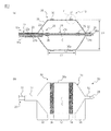
図1(a)は、本発明の一実施形態に係る十二指腸乳頭拡張用バルーンカテーテル10(以下単に、「バルーンカテーテル10」と言う。)の断面図であり、図1(b)は、バルーンカテーテル10の側面図である。バルーンカテーテル10は、カテーテルチューブ20と、バルーン30とを有している。
Hereinafter, the present invention will be described based on embodiments shown in the drawings.
FIG. 1A is a cross-sectional view of a duodenal papilla dilatation balloon catheter 10 (hereinafter simply referred to as “
カテーテルチューブ20は、可撓性材料によって形成されたチューブ本体22と、チューブ本体22に接続された連結チューブ24と、連結チューブ24に接続された先端チップ28とを有する。連結チューブ24は、チューブ本体22における体内に挿入される側の端部(遠位端)であるチューブ本体遠位端22cに固定されている。また、先端チップ28は、連結チューブ24の遠位端である連結チューブ遠位端24cに固定されている。
The
チューブ本体22の内部には、チューブ本体22の横断面図である図4(a)に示すように、ガイドワイヤルーメン22aと、バルーンルーメン22bとが形成されている。2つのルーメンは独立しており、ガイドワイヤルーメン22aと、バルーンルーメン22bは、軸方向に沿って互いに平行に延びている。
Inside the
図4(a)に示すバルーンルーメン22bは、バルーン30を膨張させるために用いる流体をバルーン30内部に送るための流路である。バルーンルーメン22bは、チューブ本体22における体外側の端部(近位端)であるチューブ本体近位端からチューブ本体遠位端22cまで延びており、バルーンルーメン22bの遠位端は、バルーン30の内部空間に開口している(図1(a))。
A
図4(a)に示すガイドワイヤルーメン22aは、バルーンカテーテル10を体内に挿入する際に、その先端部分を導くガイドワイヤを挿通させる通路の一部である。ガイドワイヤルーメン22aも、バルーンルーメン22bと同様に、チューブ本体近位端からチューブ本体遠位端22cまで延びているが、ガイドワイヤルーメン22aは、連結チューブ24のガイドワイヤルーメン24aと連通している(図1(a))。
A
図1(a)に示す連結チューブ24は、バルーン30の内部で、チューブ本体遠位端22cと、バルーン30の遠位端から露出する先端チップ28とを連結している。連結チューブ24の内部に形成されるガイドワイヤルーメン24aは、チューブ本体22のガイドワイヤルーメン22aの遠位端に接続しており、ガイドワイヤを挿通させる通路の他の一部である。また、ガイドワイヤルーメン24aの遠位端は、先端チップ28に形成された貫通孔28aに接続している。ガイドワイヤルーメン22a、24aを通るガイドワイヤの先端は、バルーンカテーテル10全体の遠位端でもある先端チップ28の貫通孔28aを介して、体内管腔に露出させることができ、あるいは、ガイドワイヤルーメン22a、24a内に引き込むことができる。
The
バルーン30の内部に位置する連結チューブ24の外周面には、2つのX線不透過性マーカー26が、バルーン30の軸方向中央Cに対して略対称の位置になるように取り付けられている。X線不透過性マーカー26は、例えばX線不透過材料である金、プラチナ、プラチナイリジウム合金等の金属や、X線造影物質の粉末を含有する樹脂組成物を用いて作製される。
Two
カテーテルチューブ20の全長は、通常500〜2500mm程度であり、チューブ本体22の外径は、通常、1.0〜3.0mm程度であるが、特に限定されない。また。図4(a)等に示すガイドワイヤルーメン22a、24a及びバルーンルーメン22bの断面形状も特に限定されず、円形、半円形、三日月形等、任意の形状とすることができる。また、チューブ本体22には、ガイドワイヤルーメン22a及びバルーンルーメン22b以外のルーメンが形成されていても良い。なお、連結チューブ24は、チューブ本体22とは別途用意したチューブを、チューブ本体遠位端22cに接続して形成されていてもよく、また、もともとチューブ本体22と一体であったチューブの一部を加工することにより形成されていてもよい。
The total length of the
各ルーメン22a、24a、22bの断面積は特に限定されないが、例えばガイドワイヤルーメン22a、24aの断面積は0.3〜1.6mm2程度とすることができ、バルーンルーメン22bの断面積は、0.2〜2.6mm2程度とすることができる。
Each
チューブ本体22及び連結チューブ24の材質は、特に限定されないが、本実施形態では可撓性を有する材質であり、例えば、ポリアミド樹脂やポリアミド系エラストマーのような高分子材料を用いることができる。また、先端チップ28の材質についても特に限定されず、ポリエチレン樹脂、ポリアミド樹脂、ポリアミド系エラストマー、ポリウレタン樹脂、ポリウレタン系エラストマー等の高分子材料を用いることができる。
Although the material of the tube
図1(a)及び図1(b)に示すように、バルーン30は、カテーテルチューブ20の遠位端に取り付けられている。バルーン30は、遠位端固定部32と近位端固定部33の2箇所で、カテーテルチューブ20に固定されている。
As shown in FIGS. 1A and 1B, the
遠位端固定部32は、バルーン30の遠位端であり、カテーテルチューブ20の遠位端に備えられる先端チップ28の外周面に固定されている。近位端固定部33は、バルーン30の近位端であり、カテーテルチューブ20の一部であるチューブ本体22の外周面に固定されている。軸方向の両端である遠位端固定部32と近位端固定部33は、カテーテルチューブ20の外周面とバルーン30の内周面との間を流体が通過できないように、カテーテルチューブ20の外周面に対して気密に固定されている。
The distal
バルーン30は、カテーテルチューブを介して供給される流体により膨張可能なバルーン膜31と、バルーン膜31の表面に設けられる第1マーカー34と第2マーカー36とを有する。図1(a)に示すように、第1マーカー34及び第2マーカー36は、バルーン30の外表面30aに、バルーン30の周方向に沿って備えられている。
The
図1(a)及び図1(b)に示すように、バルーン30は、膨張時において、外径が最大外径D1に略等しい中空円筒状部分の両端に、カテーテルチューブ20に向かって外径が縮小する傾斜部38、39が接続されたチューブ形状を呈する。第1マーカー34は、軸方向中央Cより遠位端側に設けられており、第2マーカー36は、軸方向中央Cより近位端側に設けられている。なお、バルーン30の軸方向中央Cは、遠位端固定部32の近位端と近位端固定部33の遠位端の双方から等しい距離にある。
As shown in FIGS. 1 (a) and 1 (b), the
図1(b)に示すように、第1マーカー34及び第2マーカー36は、第1マーカー34と第2マーカー36の間に配置される中央部37と伴に、膨張時において単位軸方向移動長さ当たりの外径の変化率が小さい中空円筒状部分に含まれる。すなわち、図1(b)に示すように、バルーン30のうち遠位端固定部32と近位端固定部33に挟まれた部分は、軸方向に沿って遠位端側から、傾斜部38、第1マーカー34、中央部37、第2マーカー36、傾斜部39となっている。
As shown in FIG. 1B, the
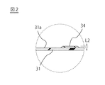
図1(a)及びその拡大図である図2に示すように、第1マーカー34及び第2マーカー36は、バルーン30の外表面30aにおける他の部分に比べて、外方向に突出している。したがって、第1マーカー34及び第2マーカー36の表面は、バルーン膜31の表面に対して、外方向に盛り上がっている。
As shown in FIG. 1A and FIG. 2 which is an enlarged view thereof, the
第1マーカー34及び第2マーカー36の材質は特に限定されないが、第1マーカー34及び第2マーカー36は、バルーン膜31には含まれない樹脂及びバルーン膜31には含まれない色材の少なくとも一方を有していてもよい。これにより、第1マーカー34及び第2マーカー36は、内視鏡での観察下において、中央部37及び傾斜部38に対して、より明確に区別して認識することが可能となる。また、第1マーカー34及び第2マーカー36は、ウレタン樹脂を含んでいてもよい。ウレタン樹脂を含む第1マーカー34及び第2マーカー36は、適切な柔軟性を有するため、バルーン30の膨張・収縮によって損傷したり、バルーン膜31から脱落したりする問題が防止される。
The material of the
第1マーカー34及び第2マーカー36は、内視鏡での観察下において中央部37及び傾斜部38、39に対して区別して認識できるように、中央部37及び傾斜部38、39(バルーン膜31)と色が異なっていることが好ましい。なお、「第1マーカー34及び第2マーカー36の色がバルーン膜31と異なる」とは、内視鏡での観察下において、目視により、バルーン膜31の表面を覆う第1マーカー34及び第2マーカー36を、バルーン膜31の表面が外表面30aに露出している中央部37及び傾斜部38、39と区別して認識できることを意図するものであり、この目的が果たされる限りにおいて、第1マーカー34及び第2マーカー36とバルーン膜31とは、色相、明度、彩度、透明度などのいずれが異なるものであってもよい。
The
バルーン膜31及びバルーン膜31が外表面30aに露出している中央部37及び傾斜部38、39の色は特に限定されないが、バルーン膨張時においても、できる限り体内管腔を観察しやすいように、例えば無色透明、又は色味があっても可視光透過率の高い透明性を有するものとすることが好ましい。第1マーカー34及び第2マーカー36の色も特に限定されないが、バルーン膜31より可視光透過率の低い、例えば黒色等のような濃色とすることが好ましいが、中央部37及び傾斜部38、39と区別して認識しやすい色であれば、特に限定されない。
The
バルーン30の大きさは、乳頭の大きさ若しくは必要な乳頭の拡張量によって調整すればよいが、膨張時におけるバルーン30の最大外径D1を例えば10〜22mm、好ましくは15〜18mmとし、バルーン30のうち外径が急激に縮小する傾斜部38、39を除いた中空円筒状部分の軸方向長さL1を、例えば30〜55mm、好ましくは40〜55mmとすることができる(図1参照)。
The size of the
図1(b)に示す本実施形態では、第1マーカー34及び第2マーカー36は、バルーン30の周方向に連続する帯状であり、リング状の形状となっている。ただし、第1マーカー34及び第2マーカー36の形状はこれに限定されず、例えば、第1マーカー34及び第2マーカー36は、周方向に断続的に形成される複数の突起等で構成されていてもよい。また、第1マーカー34及び第2マーカー36は、中央部37を除くバルーン30の外表面30a全体に設けられていてもよい。
In the present embodiment shown in FIG. 1B, the
第1マーカー34及び第2マーカー36の配置は、第1マーカー34と第2マーカー36が軸方向中央Cを挟んで設けられていれば特に限定されないが、第1マーカー34と第2マーカー36は、軸方向中央Cを挟んで対称に設けられることが好ましい。また、第1マーカー34の近位端縁から第2マーカー36の遠位端縁までの間隔、すなわち中央部37の軸方向長さは、1〜50mmとすることが好ましい。また、第1マーカー34及び第2マーカー36の軸方向長さは、2〜8mm、より好ましくは4〜8mmとすることが、内視鏡下における第1マーカー34、第2マーカー36の認識しやすさと、適切な位置へのバルーンの配置の容易さを両立させる観点から好ましい。また、図2に示す第1マーカー34(及び第2マーカー36)の厚みL2は、特に限定されないが、例えば0.1〜3mmとすることができる。
The arrangement of the
バルーン膜31の材質は、特に限定されないが、ある程度の可撓性を有し、かつ、乳頭に挿入して膨張させることにより乳頭を拡張できる程度の剛性を有する材質であることが好ましく、例えばポリエチレン、ポリエチレンテレフタレート、ポリプロピレン、エチレン−プロピレン共重合体等のエチレンと他のα−オレフィンとの共重合体、エチレン−酢酸ビニル共重合体、ポリ塩化ビニル(PVC)、架橋型エチレン−酢酸ビニル共重合体、ポリウレタン、ポリアミド、ポリアミドエラストマー、ポリイミド、ポリイミドエラストマー、シリコーンゴムなどが使用できる。
The material of the
バルーン膜31は、上述した材料を用いて、バルーンの成形法として従来公知の各種の成形法、例えばブロー成形法などを適用して製造することができる。バルーン膜31の肉厚は、例えば、0.01〜0.50mm程度とすることができるが、特に限定されない。
The
また、バルーン膜31に第1マーカー34及び第2マーカー36を形成する方法も特に限定されず、例えば、バルーン膜31における第1マーカー34及び第2マーカー36を形成すべき部分の表面又は裏面にインクを付着させることにより第1マーカー34及び第2マーカー36を形成する方法や、バルーン膜31の成膜時に用いる金型に凹凸を設けて、第1マーカー34及び第2マーカー36に相当する起伏を外表面に形成する方法が挙げられる。なお、内視鏡での観察下のみならず、X線画像においても認識できるように、第1マーカー34及び第2マーカー36の少なくとも一部をX線不透過材料で形成してもよい。
Further, the method for forming the
バルーン30の両端部をチューブ本体22及び先端チップ28の外周面に固定し、遠位端固定部32及び近位端固定部33を形成する方法としては、特に限定されないが、例えば接着剤による接着、熱融着、溶剤による溶着、超音波溶着等の手法が挙げられる。
The method for fixing the both ends of the
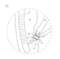
次に、図1に示すバルーンカテーテル10の使用例について説明する。図3は、図1に示す十二指腸乳頭拡張用バルーンカテーテル10の使用例を示す概念図である。
Next, a usage example of the
バルーンカテーテル10は、胆管内の胆石を体外に取り出して除去する総胆管結石治療を行う際、胆石を砕いたり取り出したりする前に、十二指腸から総胆管62への接続部である乳頭64を拡張するために使用される。図3に示すように、予め十二指腸60の所定位置にセットされた内視鏡50のチャネルを介して、バルーンカテーテル10の遠位端を、乳頭64まで挿入する。
The
バルーンカテーテル10の挿入は、予め総胆管62の内部に挿入されたガイドワイヤ(不図示)を、カテーテルチューブ20のガイドワイヤルーメン22a、24aに挿通させ、ガイドワイヤに沿わせながら行う。バルーンカテーテル10の遠位端に取り付けられたバルーン30が、内視鏡50の遠位端に形成されたチャネル開口から露出し、乳頭64近傍に到達したことは、連結チューブ24に取り付けられたX線不透過性マーカー26の位置をX線画像で認識することにより確認することができる。なお、バルーンカテーテル10の挿入時において、バルーン30は収縮した状態であり、バルーン膜31の内周面は、バルーン30内部のチューブ本体22及び連結チューブ24の外周面に密着している。
The
次に、内視鏡下で乳頭64周辺を確認しながら、バルーン30が乳頭64に対して適切に配置されるように、バルーン30の位置合わせを行う。この際、十二指腸60側から撮影する内視鏡視野において、バルーン30の第1マーカー34は、乳頭64から総胆管62側へ入っており、内視鏡下では認識できず、第2マーカー36のみが乳頭64から露出し、内視鏡下で認識できる位置に、バルーン30の位置を調整する。これにより、バルーン30の軸方向中央C(図1参照)が、概ね乳頭括約筋66の内側に位置するように、バルーン30を配置することができる。
Next, while confirming the periphery of the
次に、カテーテルチューブ20のバルーンルーメン22bを介してバルーン30の内部に生理食塩水等の流体を充填し、バルーン30を膨張させる。バルーン30の膨張により、乳頭64が所望の大きさまで拡張したことを確認した後、バルーンルーメン22bを介してバルーン30内部から流体を排出しバルーン30を収縮させた後、バルーン30を引き出す。
Next, the
以上のように、本実施形態に係るバルーンカテーテル10は、バルーン30の軸方向中央Cより遠位端側に設けられる第1マーカー34と、軸方向中央Cより近位端側に設けられる第2マーカー36とを有するため、これを内視鏡下で確認しながらバルーン30の位置合わせをすることにより、バルーン30の軸方向中央C(図1参照)が、概ね乳頭括約筋66の内側に位置するように、バルーン30を配置することができる。一般的に、十二指腸乳頭拡張用バルーンカテーテルは、バルーンの膨張時に、乳頭64にある乳頭括約筋66から、バルーンの膨張を押し戻す方向に力を受けるため、バルーンの配置位置が適切でない場合には、バルーンの膨張の過程でバルーンが乳頭64からずれてしまう場合がある。
As described above, the
しかし、本実施形態に係るバルーンカテーテル10は、単にバルーン30の位置が分かるだけではなく、バルーン30の軸方向中央Cと乳頭64との位置合わせを正確に行えるように、第1マーカー34と第2マーカー36とを有する。このため、バルーンカテーテル10による十二指腸乳頭拡張術では、バルーン30が正確に位置合わせされることにより、バルーン30を膨張させて乳頭64を拡張する際に、バルーン30が乳頭64からずれにくくなる。
However, the
また、第1マーカー34及び第2マーカー36は、バルーン膜31の表面より外方向へ突出しているため、バルーン30が前後いずれの方向にずれを生じようとした場合にでも、第1マーカー34及び第2マーカー36による盛り上がりが乳頭64に引っかかる。そのため、バルーンカテーテル10は、バルーン30を膨張させて乳頭64を拡張する際におけるバルーン30のスリップを防止できる。また、このようなバルーンカテーテル10は、第1マーカー34及び第2マーカー36がスリップ防止の効果を兼ねるため、例えば中央部37にスリップ防止の形状を付与したようなものに比べて製造が容易である。また、中央部37自体又はバルーン膜31自体には、スリップ防止の形状を付与する必要がないため、バルーン30の表面で発生する光の反射や散乱により、マーカーが見えにくくなる問題も発生しにくい。
In addition, since the
上述のように、実施形態に係るバルーンカテーテル10を用いて本発明を説明してきたが、本発明はこの実施形態に限定されず、他の様々な実施形態が本発明に含まれる。例えば、バルーンカテーテル10に用いられるチューブ本体22は、図4(a)に示すダブルルーメン型のものに限定されず、図4(b)に示すように、ガイドワイヤルーメン72aとバルーンルーメン72bとが同心円状に形成される二重管構造型のチューブ本体72であっても良い。
As described above, the present invention has been described using the
10…十二指腸乳頭拡張用バルーンカテーテル
20…カテーテルチューブ
22、72…チューブ本体
22a、24a、72a…ガイドワイヤルーメン
22b、72b…バルーンルーメン
24…連結チューブ
28…先端チップ
30…バルーン
31…バルーン膜
32…遠位端固定部
33…近位端固定部
34…第1マーカー
36…第2マーカー
37…中央部
38、39…傾斜部
66…乳頭括約筋
DESCRIPTION OF
Claims (3)
前記カテーテルチューブの遠位端に接続しており、前記カテーテルチューブを介して供給される流体により膨張可能なバルーンと、を有し、
前記バルーンの外表面には、当該外表面における隣接部分に比べて外方向へ突出する第1マーカー及び第2マーカーが、前記バルーンの周方向に沿って備えられており、
前記第1マーカーは、前記バルーンの軸方向中央より遠位端側に設けられており、前記第2マーカーは、前記軸方向中央より近位端側に設けられていることを特徴とする十二指腸乳頭拡張用バルーンカテーテル。 A catheter tube;
A balloon connected to a distal end of the catheter tube and inflatable by a fluid supplied through the catheter tube;
The outer surface of the balloon is provided with a first marker and a second marker protruding outward compared to the adjacent portion on the outer surface along the circumferential direction of the balloon,
The first marker is provided on the distal end side from the axial center of the balloon, and the second marker is provided on the proximal end side from the axial center. Expansion balloon catheter.
前記第1マーカー及び前記第2マーカーは、前記バルーン膜には含まれない樹脂及び前記バルーン膜には含まれない色材の少なくとも一方を有することを特徴とする請求項1に記載の十二指腸乳頭拡張用バルーンカテーテル。 The balloon has a balloon membrane that can be inflated by the fluid, and the first marker and the second marker provided on the surface of the balloon membrane,
The duodenal papilla extension according to claim 1, wherein the first marker and the second marker have at least one of a resin not included in the balloon membrane and a color material not included in the balloon membrane. Balloon catheter.
Priority Applications (1)
| Application Number | Priority Date | Filing Date | Title |
|---|---|---|---|
| JP2015249493A JP2017113123A (en) | 2015-12-22 | 2015-12-22 | Balloon catheter for duodenal papilla dilatation |
Applications Claiming Priority (1)
| Application Number | Priority Date | Filing Date | Title |
|---|---|---|---|
| JP2015249493A JP2017113123A (en) | 2015-12-22 | 2015-12-22 | Balloon catheter for duodenal papilla dilatation |
Publications (1)
| Publication Number | Publication Date |
|---|---|
| JP2017113123A true JP2017113123A (en) | 2017-06-29 |
Family
ID=59233135
Family Applications (1)
| Application Number | Title | Priority Date | Filing Date |
|---|---|---|---|
| JP2015249493A Pending JP2017113123A (en) | 2015-12-22 | 2015-12-22 | Balloon catheter for duodenal papilla dilatation |
Country Status (1)
| Country | Link |
|---|---|
| JP (1) | JP2017113123A (en) |
Cited By (4)
| Publication number | Priority date | Publication date | Assignee | Title |
|---|---|---|---|---|
| JP2019097597A (en) * | 2017-11-28 | 2019-06-24 | 株式会社カネカ | Balloon catheter and actuation method thereof |
| CN111481807A (en) * | 2020-05-19 | 2020-08-04 | 上海市东方医院(同济大学附属东方医院) | Biliary tract internal drainage tube for preventing duodenal papilla hemorrhage |
| JP2021115364A (en) * | 2020-01-29 | 2021-08-10 | テルモ株式会社 | Balloon catheter |
| WO2025070409A1 (en) * | 2023-09-28 | 2025-04-03 | テルモ株式会社 | Balloon, light irradiation device, and treatment method |
-
2015
- 2015-12-22 JP JP2015249493A patent/JP2017113123A/en active Pending
Cited By (5)
| Publication number | Priority date | Publication date | Assignee | Title |
|---|---|---|---|---|
| JP2019097597A (en) * | 2017-11-28 | 2019-06-24 | 株式会社カネカ | Balloon catheter and actuation method thereof |
| JP2021115364A (en) * | 2020-01-29 | 2021-08-10 | テルモ株式会社 | Balloon catheter |
| JP7364482B2 (en) | 2020-01-29 | 2023-10-18 | テルモ株式会社 | balloon catheter |
| CN111481807A (en) * | 2020-05-19 | 2020-08-04 | 上海市东方医院(同济大学附属东方医院) | Biliary tract internal drainage tube for preventing duodenal papilla hemorrhage |
| WO2025070409A1 (en) * | 2023-09-28 | 2025-04-03 | テルモ株式会社 | Balloon, light irradiation device, and treatment method |
Similar Documents
| Publication | Publication Date | Title |
|---|---|---|
| US12042613B2 (en) | Balloon catheter | |
| CN108290027B (en) | Catheter with lumen shaped as identification symbol | |
| ES2971264T3 (en) | balloon catheter | |
| US10357638B2 (en) | Reinforced balloon catheter | |
| ES2828972T3 (en) | Intravascular catheter having an expandable incision portion and drug delivery mechanism | |
| JP4443278B2 (en) | Catheter with expansion body | |
| KR101886551B1 (en) | Catheter with radiofrequency cutting tip and heated balloon | |
| ES2955387T3 (en) | Balloon catheter assembly for insertion and positioning of therapeutic devices within a vascular system | |
| JP6901971B2 (en) | Inflatable perfusion balloon with outer mesh and related methods | |
| JP7640568B2 (en) | Medical Device with Balloon and Removal Member - Patent application | |
| US20160279393A1 (en) | Guidewire retrieval catheter | |
| US10561828B2 (en) | Treatment tool for endoscope | |
| ES2711224T3 (en) | Catheter with vascular occlusion balloon | |
| US10850075B2 (en) | Balloon catheter and manufacturing method of elongated member for balloon catheter | |
| CN105283141A (en) | Vacuum-assisted pancreaticobiliary cannulation | |
| JP2017113123A (en) | Balloon catheter for duodenal papilla dilatation | |
| JP2011507663A (en) | Two-part extraction balloon | |
| AU2019279092B2 (en) | Dilation device and method of use | |
| JP2019500116A (en) | Radiation directional balloon visualization device | |
| EP2405814B1 (en) | A device for protecting a catheter | |
| US8029494B2 (en) | Method of removing biliary stones with coaxial catheter device | |
| JP2020039376A (en) | Balloon catheter | |
| JP2016019623A (en) | Balloon catheter for duodenal papilla extension | |
| KR20220014842A (en) | Enhanced balloon bonding for balloon guide catheters while minimizing outer profiles | |
| US10517623B2 (en) | Removal tool for use with endoscopic device |