JP2017113232A - Washing machine control method - Google Patents
Washing machine control method Download PDFInfo
- Publication number
- JP2017113232A JP2017113232A JP2015251163A JP2015251163A JP2017113232A JP 2017113232 A JP2017113232 A JP 2017113232A JP 2015251163 A JP2015251163 A JP 2015251163A JP 2015251163 A JP2015251163 A JP 2015251163A JP 2017113232 A JP2017113232 A JP 2017113232A
- Authority
- JP
- Japan
- Prior art keywords
- water
- balancer
- unbalance
- water injection
- washing machine
- Prior art date
- Legal status (The legal status is an assumption and is not a legal conclusion. Google has not performed a legal analysis and makes no representation as to the accuracy of the status listed.)
- Pending
Links
Images



Classifications
-
- D—TEXTILES; PAPER
- D06—TREATMENT OF TEXTILES OR THE LIKE; LAUNDERING; FLEXIBLE MATERIALS NOT OTHERWISE PROVIDED FOR
- D06F—LAUNDERING, DRYING, IRONING, PRESSING OR FOLDING TEXTILE ARTICLES
- D06F33/00—Control of operations performed in washing machines or washer-dryers
- D06F33/30—Control of washing machines characterised by the purpose or target of the control
- D06F33/48—Preventing or reducing imbalance or noise
-
- D—TEXTILES; PAPER
- D06—TREATMENT OF TEXTILES OR THE LIKE; LAUNDERING; FLEXIBLE MATERIALS NOT OTHERWISE PROVIDED FOR
- D06F—LAUNDERING, DRYING, IRONING, PRESSING OR FOLDING TEXTILE ARTICLES
- D06F37/00—Details specific to washing machines covered by groups D06F21/00 - D06F25/00
- D06F37/20—Mountings, e.g. resilient mountings, for the rotary receptacle, motor, tub or casing; Preventing or damping vibrations
- D06F37/24—Mountings, e.g. resilient mountings, for the rotary receptacle, motor, tub or casing; Preventing or damping vibrations in machines with a receptacle rotating or oscillating about a vertical axis
- D06F37/245—Damping vibrations by displacing, supplying or ejecting a material, e.g. liquid, into or from counterbalancing pockets
-
- D—TEXTILES; PAPER
- D06—TREATMENT OF TEXTILES OR THE LIKE; LAUNDERING; FLEXIBLE MATERIALS NOT OTHERWISE PROVIDED FOR
- D06F—LAUNDERING, DRYING, IRONING, PRESSING OR FOLDING TEXTILE ARTICLES
- D06F2103/00—Parameters monitored or detected for the control of domestic laundry washing machines, washer-dryers or laundry dryers
- D06F2103/26—Imbalance; Noise level
-
- D—TEXTILES; PAPER
- D06—TREATMENT OF TEXTILES OR THE LIKE; LAUNDERING; FLEXIBLE MATERIALS NOT OTHERWISE PROVIDED FOR
- D06F—LAUNDERING, DRYING, IRONING, PRESSING OR FOLDING TEXTILE ARTICLES
- D06F2105/00—Systems or parameters controlled or affected by the control systems of washing machines, washer-dryers or laundry dryers
-
- D—TEXTILES; PAPER
- D06—TREATMENT OF TEXTILES OR THE LIKE; LAUNDERING; FLEXIBLE MATERIALS NOT OTHERWISE PROVIDED FOR
- D06F—LAUNDERING, DRYING, IRONING, PRESSING OR FOLDING TEXTILE ARTICLES
- D06F2105/00—Systems or parameters controlled or affected by the control systems of washing machines, washer-dryers or laundry dryers
- D06F2105/02—Water supply
-
- D—TEXTILES; PAPER
- D06—TREATMENT OF TEXTILES OR THE LIKE; LAUNDERING; FLEXIBLE MATERIALS NOT OTHERWISE PROVIDED FOR
- D06F—LAUNDERING, DRYING, IRONING, PRESSING OR FOLDING TEXTILE ARTICLES
- D06F37/00—Details specific to washing machines covered by groups D06F21/00 - D06F25/00
- D06F37/02—Rotary receptacles, e.g. drums
- D06F37/12—Rotary receptacles, e.g. drums adapted for rotation or oscillation about a vertical axis
- D06F37/14—Ribs or rubbing means forming part of the receptacle
Landscapes
- Engineering & Computer Science (AREA)
- Textile Engineering (AREA)
- Control Of Washing Machine And Dryer (AREA)
- Main Body Construction Of Washing Machines And Laundry Dryers (AREA)
- Detail Structures Of Washing Machines And Dryers (AREA)
Abstract
【課題】洗濯槽の偏心による振動や騒音の発生を抑制し、且つ運転時間の遅延を有効に回避することができる洗濯機の制御方法を提供する。【解決手段】洗濯機の制御方法は、脱水工程において、アンバランス位置(N)を検出するアンバランス位置検出ステップと、注水を要するバッフルを決定するバランサ選択ステップと、少なくとも二つのバッフルに注水を要するときにアンバランス位置から最も離間したバッフルに給水バルブXにより調整水を注水する第一注水ステップSPと、洗濯槽のアンバランス量(M)の推移を検出するアンバランス量検出ステップSP12と、このアンバランス量検出ステップSP12により検出されるアンバランス量(M)が上昇に転じたときに給水バルブXから給水バルブZへ注水を切り替える注水切り替えステップSP18とを具備する。【選択図】図8To provide a method for controlling a washing machine capable of suppressing the occurrence of vibration and noise due to eccentricity of a washing tub and effectively avoiding a delay in operation time. A washing machine control method includes: an unbalance position detection step for detecting an unbalance position (N); a balancer selection step for determining a baffle that requires water injection; and water injection to at least two baffles. A first water injection step SP for injecting adjustment water to the baffle farthest away from the unbalance position when necessary by the water supply valve X, an unbalance amount detection step SP12 for detecting the transition of the unbalance amount (M) of the washing tub, A water injection switching step SP18 for switching water injection from the water supply valve X to the water supply valve Z when the unbalance amount (M) detected in the unbalance amount detection step SP12 starts to increase is provided. [Selection] Figure 8
Description
本発明は、脱水工程における洗濯槽のアンバランスを解消して、脱水時における洗濯槽の偏心による振動や騒音を抑制可能な洗濯機の制御方法に関する。 The present invention relates to a method for controlling a washing machine that can eliminate imbalance of a washing tub in a dehydration process and suppress vibration and noise due to eccentricity of the washing tub during dehydration.
一般家庭あるいはコインランドリーなどに設置される一般的な洗濯機は、脱水時に脱水槽内で洗濯物が偏って振動や騒音が発生する。この振動や騒音は、洗濯機の設置場所や周辺環境によってはトラブルに発展することがある。また、そのときの洗濯物の偏りが大きい場合、回転時の洗濯槽の偏心が大きくなり、回転に大きなトルクが必要となるので脱水運転を開始することができない。 In a general washing machine installed in a general household or a coin laundry, laundry is biased in the dehydration tank during dehydration, and vibration and noise are generated. This vibration and noise may develop into trouble depending on the location of the washing machine and the surrounding environment. In addition, if the laundry is biased at that time, the washing tub becomes more eccentric during rotation, and a large torque is required for rotation, so the dehydration operation cannot be started.
そこで、特許文献1には、脱水時に洗濯槽内の衣類のアンバランス量およびアンバランス位置を検出し、アンバランスがある場合には、洗濯槽の回転にブレーキを掛けて遠心力を低下させ、アンバランスの原因となる衣類の塊を重力で落下させて分散させる技術が開示されている。
Therefore,
また、特許文献2には、低速回転時に洗濯槽のアンバランスの有無を判定し、アンバランスが検知された場合にはモータを停止するとともに、アンバランス状態の解消のために洗濯槽に注水して衣類の塊を解きほぐす技術が開示されている。
Further, in
しかしながら、特許文献1に開示の構成では、脱水工程における脱水槽の低速回転時にしかアンバランス検出と分散作業ができず、脱水槽の高速回転起動後に衣類の種類などの影響で再度アンバランスが発生するおそれがある。
However, in the configuration disclosed in
また、上記特許文献1、2に開示の構成は、アンバランスが検知されると脱水槽の回転を減速あるいは停止させるので、脱水運転を繰り返す毎に起動電力が必要となり消費電力が大きくなるばかりか、洗濯に要する時間すなわち運転時間が遅延してしまうという問題がある。さらに特許文献2では、消費電力の増加に加えて水の使用量が増えるという問題がある。
In addition, the configurations disclosed in
そして、特にコインランドリーに設置される洗濯機にあっては、上述したような運転時間の遅延は、店舗における顧客の回転効率の低下を招来してしまうことになる。 In particular, in a washing machine installed in a coin laundry, the delay in the operation time as described above causes a reduction in the rotational efficiency of the customer in the store.
本発明は、このような課題を有効に解決することを目的としており、脱水運転時に脱水槽内で洗濯物の偏在があっても回転を減速あるいは停止することなく洗濯槽のアンバランスを解消して、洗濯槽の偏心による振動や騒音の発生を抑制し、且つ運転時間の遅延を有効に回避することができる洗濯機の制御方法を提供することを目的としている。 An object of the present invention is to effectively solve such a problem, and even if there is uneven distribution of laundry in the dehydration tank during the dehydration operation, the unbalance of the laundry tub is eliminated without decelerating or stopping the rotation. Thus, an object of the present invention is to provide a washing machine control method capable of suppressing generation of vibration and noise due to eccentricity of a washing tub and effectively avoiding a delay in operation time.
本発明は以上のような問題点を鑑み、次のような手段を講じたものである。 The present invention takes the following measures in view of the above problems.
すなわち、本発明の洗濯機の制御方法は、洗濯槽の内周面に軸線周りに角度位相を異ならせて3つ以上配設される中空のバランサと、前記バランサの各々に個別に調整水を注水する注水装置とを備えてなる洗濯機の制御方法であって、脱水工程において、前記洗濯槽のアンバランス位置を検出するアンバランス位置検出ステップと、このアンバランス位置検出ステップにより注水を要する前記バランサを決定するバランサ選択ステップと、このバランサ選択ステップにより少なくとも二つの前記バランサに注水を要するときに複数のバランサのうちの任意の第一のバランサに前記調整水を注水する第一注水ステップと、この第一注入ステップ中の前記洗濯槽のアンバランス量の推移を検出するアンバランス量検出ステップと、このアンバランス量検出ステップにより検出されるアンバランス量が上昇に転じたときに前記調整水の注水を前記第一のバランサから第二のバランサへ切り替える注水切り替えステップと、前記第二バランサへ前記調整水を注水する第二注水ステップとを具備することを特徴とする。 That is, in the washing machine control method of the present invention, three or more hollow balancers are provided on the inner peripheral surface of the washing tub with different angular phases around the axis, and adjustment water is individually applied to each of the balancers. A method for controlling a washing machine comprising a water pouring device for pouring water, wherein in the dewatering step, an unbalance position detecting step for detecting an unbalanced position of the washing tub, and the unbalanced position detecting step requires water pouring. A balancer selection step for determining a balancer; and a first water injection step for injecting the adjusted water to any first balancer of the plurality of balancers when water is required for at least two of the balancers by the balancer selection step; An unbalance amount detecting step for detecting a change in the unbalance amount of the washing tub during the first injection step; A water injection switching step of switching the adjustment water injection from the first balancer to the second balancer when the unbalance amount detected by the amount detection step starts to increase, and water injection of the adjustment water to the second balancer And a second water injection step.
また本発明は、第一のバランサが、アンバランス位置から最も大きく離間した位置にあるバランサであることを特徴とする。 Further, the present invention is characterized in that the first balancer is a balancer at a position farthest from the unbalanced position.
また本発明は、第一注水ステップから注水切り替えステップに至るまでに所定時間経過したときに調整水の注水を第一のバランサから第二のバランサへ切り替える時間切り替えステップを有していることを特徴とする。 Moreover, this invention has the time switching step which switches the injection of adjustment water from a 1st balancer to a 2nd balancer when predetermined time passes from a 1st water injection step to a water injection switching step. And
また本発明は、バランサが、洗濯槽の内周面から突出させて設けられた洗濯物を攪拌し得るバッフルであることを特徴とする。 Further, the present invention is characterized in that the balancer is a baffle capable of stirring the laundry provided to protrude from the inner peripheral surface of the washing tub.
また本発明は、バランサが、洗濯槽の内周面に沿って等角度間隔で設けられていることを特徴とする。 Moreover, the present invention is characterized in that the balancers are provided at equiangular intervals along the inner peripheral surface of the washing tub.
以上、説明した本発明によれば、複数のバランサに注水を要するときであっても注水に要する時間をアンバランスの解消に適したものとすることができる。これによりアンバランスの解消に要する時間が必要以上に長期化することを回避し、脱水工程を円滑に行わせることができる。つまり本発明によれば、脱水運転時に洗濯槽内で洗濯物の偏在があっても回転を減速あるいは停止することなく洗濯槽のアンバランスを解消して、洗濯槽の偏心による振動や騒音の発生を抑制し、且つ運転時間の遅延を有効に回避することができる。その結果、使用者が洗濯に要する時間が遅延しないため、使用者の時間の有効利用やコインランドリー店舗の回転効率の向上にも資する。 As described above, according to the present invention described above, even when water is required for a plurality of balancers, the time required for water injection can be made suitable for resolving unbalance. As a result, it is possible to prevent the time required for eliminating the imbalance from becoming longer than necessary, and to smoothly perform the dehydration process. That is, according to the present invention, even if there is uneven distribution of laundry in the washing tub during dehydration operation, the unbalance of the washing tub is eliminated without slowing down or stopping the rotation, and vibration and noise are generated due to the eccentricity of the washing tub. Can be suppressed, and a delay in operation time can be effectively avoided. As a result, the time required for the user to wash is not delayed, which contributes to effective use of the user's time and improvement in the rotation efficiency of the coin laundry store.
また、第一のバランサが、アンバランス位置から最も大きく離間した位置にあるバランサである本発明によれば、アンバランスの解消に最も資するバランサに注水することでアンバランスの量を速やかに減少させつつ注水切り替えステップによって必要十分な時間だけ注水させ得るため、より速やかなアンバランスの解消に寄与している。 In addition, according to the present invention, in which the first balancer is the balancer that is most distant from the unbalance position, the amount of unbalance can be quickly reduced by pouring water into the balancer that most contributes to the elimination of the unbalance. However, since the water injection switching step allows water to be injected for a necessary and sufficient time, it contributes to the quicker imbalance cancellation.
また、上述のような時間切り替えステップを有している本発明によれば、第一のバランサへの注水がアンバランスの解消度合いが低いとされるようなときであっても必要以上に注水が長期化することを回避して、よりアンバランスの解消に寄与し得る。 Further, according to the present invention having the time switching step as described above, water injection to the first balancer can be performed more than necessary even when the degree of unbalance cancellation is low. This can contribute to the elimination of the unbalance by avoiding the longer period.
また、バランサが洗濯物を攪拌し得るバッフルである本発明によれば、既存の構成を有効に利用することで装置の大型化を回避するのみならず、製造に要する部品点数の増加を有効に回避し、より効率の高い製造にも資するものとなる。 In addition, according to the present invention in which the balancer is a baffle capable of stirring the laundry, the existing configuration can be effectively used to not only increase the size of the apparatus but also effectively increase the number of parts required for manufacturing. It avoids and contributes to more efficient production.
また、バランサが等角度間隔で設けられている本発明によれば、アンバランス位置の特定から注水を要するバランサの特定までの制御をよりシンプルなものとしつつ、効率の高いアンバランスの解消を行うことができる。 Further, according to the present invention in which the balancers are provided at equiangular intervals, the control from the unbalance position specification to the balancer specification that requires water injection is made simpler, and high-efficiency unbalance is eliminated. be able to.
以下、本発明の一実施形態を図に基づいて詳細に説明する。 Hereinafter, an embodiment of the present invention will be described in detail with reference to the drawings.
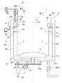
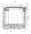
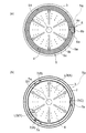
図1は本発明の一実施形態に係る縦型の洗濯機(以下、「洗濯機」と称す。)1の外観を示す斜視図である。図2は、本実施形態の洗濯機1の構成を示す模式図である。図3は、本実施形態の洗濯機1の部分的な縦断面斜視図である。図4は、本実施形態の洗濯機1の一部を上方から見た図であり、図4(a)は平面図、図4(b)は洗濯機1が有する脱水槽2の横断面図である。図5は、本実施形態の洗濯機1の部分的な縦断面図である。
FIG. 1 is a perspective view showing an appearance of a vertical washing machine (hereinafter referred to as “washing machine”) 1 according to an embodiment of the present invention. FIG. 2 is a schematic diagram illustrating a configuration of the
本実施形態の洗濯機1は、洗濯機本体1aと、洗濯槽1bを構成する外槽3並びに脱水槽2と、受水リングユニット5と、ノズルユニット6と、駆動部40と、制御手段(図6参照)とを備える。
The
図1に示す洗濯機本体1aは、略直方体形状である。洗濯機本体1aの上面10aには、脱水槽2に対して洗濯物を出し入れするための開口11が形成されるとともに、この開口11を開閉可能な開閉蓋11aが取り付けられる。
The washing machine
外槽3は、洗濯機本体1aの内部に配置された洗濯槽1bの外形を構成する有底筒状の部材であり、内部に洗濯水を貯留可能である。図2に示すように、外槽3の外周面3aには、水平と垂直の2方向の加速度を検出可能な加速度センサ12が取り付けられる。
The
脱水槽2は、外槽3内において外槽3と同軸に配置されて外槽3とともに洗濯槽1bを構成するとともに、回転自在に支持される有底筒状の部材である。脱水槽2は、内部に洗濯物を収容可能で、その壁面2aに多数の通水孔2b(図3参照)を有する。
The dewatering
このような脱水槽2の底部2c中央には、パルセータ(撹拌翼)4が回転自在に配置される。図3に示すように、パルセータ4は、略円盤形状のパルセータ本体4bと、パルセータ本体4bの上面に形成される複数の上羽根部4cと、パルセータ本体4bの下面に形成される複数の下羽根部4aとを有する。このようなパルセータ4は、外槽3内に貯留された洗濯水を撹拌して水流を発生させる。
A pulsator (stirring blade) 4 is rotatably arranged at the center of the bottom 2c of the
図3,4(b)に示すように、脱水槽2の内周面2a1には、周方向に等間隔(等角度)で通水管部として、そして本発明ではバランサに相当するバッフル(注水管)7が3つ設けられる。各バッフル7は、脱水槽2の底部2cから上端部に亘って上下方向に延び、脱水槽2の内周面2a1から軸線S1に向けて突出して形成される。また各バッフル7は、中空状であり、横断面形状が円弧状に形成される。斯かる形状によりこのバランサとしてのバッフルは脱水工程において洗濯物を攪拌する作用をも奏する。このように、バッフル7の形状が、脱水槽2の軸線S1への突出が小さく、脱水槽2の周方向に沿って広がる形状であることで、脱水槽2の収容空間が狭くなることを抑制できる。
As shown in FIGS. 3 and 4 (b), the inner peripheral surface 2a1 of the
図2,3に示すように、このようなバッフル7の下端部には、脱水槽2の底部2c近傍、より具体的にはパルセータ本体4bよりも下方で開口する開口部71が形成される。また、バッフル7の上端部には、横長の循環水口70が形成される。そのため、排水バルブ50a(図2参照)が閉じられて外槽3内に洗濯水が貯められた状態にある洗い工程では、図3において矢印で示すように、パルセータ4の下羽根部4aで撹拌された洗濯水が開口部71より浸入してバッフル7内をかけあがり、循環水口70より吐出され、衣類がシャワー洗いされる。またこの動作が繰り返されることで、洗濯水が脱水槽2内で循環する。すなわち、バッフル7は、洗濯水の循環機能を有する。なお、このように開口部71および循環水口70を有し、シャワー洗いを行える通水管部は、従来の洗濯機にも適用されるが、通常1つだけ設けられる。
As shown in FIGS. 2 and 3, an
さらに、バッフル7の内部には、後述する連通部材5a1,5b1,5c1が接続される位置と循環水口70との間から脱水槽2の内周面2a1の近接位置まで延びる仕切片7aが設けられる。仕切片7aは、循環水口70の上端縁から延びて、自由端7a1側が下方に湾曲する。このような仕切片7aの自由端7a1と脱水槽2の内周面2a1との間には隙間7b(図2参照)が形成されており、受水リングユニット5から供給される後述する調整水は、この隙間7bを介して下方に流れ込む。
Further, inside the
受水リングユニット5は、本発明の注水装置1cを構成するものであり、上方に向けて開放された環状の導水樋5a、5b、5c(図4(a)参照)が脱水槽2の軸線S1に向けて径方向に三層重層されて構成されるもので、図3に示すように脱水槽2の内周面2a1の上端部に固定される。導水樋5a、5b、5cは、バッフル7と同数だけ設けられ、単独で何れかのバッフル7に調整水を流せる通水経路が内部に形成される。このような受水リングユニット5は、従来の洗濯機に取り付けられる既知の液体バランサと大きさおよび形状がほぼ同一であり、本実施形態では、一般的な液体バランサの取付位置に液体バランサに代わって取り付けられる。液体バランサは、脱水時に脱水槽2のアンバランスを受動的に解消する働きをするが、後述するように脱水槽2のアンバランスを能動的に解消できる受水リングユニット5と比べて、その効果は小さい。
The water-receiving
このような受水リングユニット5とバッフル7の上端部とは、連通部材5a1、5b1、5c1でそれぞれ接続される。連通部材5a1、5b1、5c1は、循環水口70よりも上方でバッフル7に接続される。
Such a water
ノズルユニット6は、本発明の注水装置1cを構成するものであり、このような導水樋5a、5b、5cに個別に調整水を注水するものである。ノズルユニット6は、導水樋5a、5b、5cの上方に配置された3本の注水ノズル6a、6b、6cと、これらの注水ノズル6a、6b、6cにそれぞれ接続される給水バルブ26a、26b、26cとを有する。注水ノズル6a、6b、6cは、導水樋5a、5b、5cと同数だけ設けられ、それぞれ別々の導水樋5a、5b、5cに注水可能な位置に配置される。なお、本実施形態では調整水として水道水が用いられる。また、給水バルブ26a、26b、26cとしては、方向切換給水バルブを採用することも可能である。
The
すなわち、受水リングユニットとノズルユニットによって、本発明に係る注水装置1cが構成される。
That is, the
このような注水装置1cの構成であると、排水バルブ50aが開かれて外槽3内の洗濯水が排水口50より排出される脱水工程では、ノズルユニット6の何れかの注水ノズル6a、6b、6cから受水リングユニット5の導水樋5a、5b、5c内に注入された調整水は、連通部材5a1,5b1,5c1を介してバッフル7内に流れ込む。例えば、注水ノズル6cから調整水が注入される場合には、図5に矢印で示すように、導水樋5cから連通部材5c1を介してバッフル7に調整水が流れ込む。バッフル7内に流れ込んだ調整水は、脱水槽2が高速回転状態にあると、遠心力により脱水槽2の内周面2a1にはりついて滞留する。これにより当該バッフル7の重量が増加し、脱水槽2のバランスが変化する。このようにバッフル7は、遠心力により調整水を貯めることが可能なポケットバッフル構造である。そして、脱水工程が終了に近づいて脱水槽2の回転速度が低下すると、バッフル7内の遠心力が次第に減衰し、調整水が重力によって開口部71から流れ出て、排水管5を介して外槽3外へ排水される。このとき、調整水は開口部71を介してパルセータ本体4bの下方に流れ込む。そのため、調整水は、パルセータ本体4bよりも上方にある衣類を濡らすことなく排水される。
With such a configuration of the
図2に示す駆動部40は、モータ10によりプーリー15,15およびベルト15bを回転させるとともに、脱水槽2の底部2cに向けて延出する駆動軸17を回転させて、脱水槽2やパルセータ4に駆動力を与え、脱水槽2やパルセータ4を回転させる。洗濯機1は、洗い工程では主としてパルセータ4のみを回転させ、脱水工程では脱水槽2とパルセータ4とを一体的に高速で回転させる。また、一方のプーリー15の近傍には、当該プーリー15に形成されたマーク15aの通過を検出できる近接スイッチ14が設けられる。
The
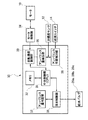
図6は、本実施形態の洗濯機1の電気的構成を示すブロック図である。この洗濯機1の動作は、マイクロコンピュータを含む制御手段30によって制御される。制御手段30は、システム全体の制御を司る中央制御部(CPU)31を備え、この制御手段30に脱水槽2の回転制御に必要な脱水運転開始前の低速回転設定値(N1)、脱水運転開始後の高速回転設定値(N2)、低速脱水運転時のアンバランス量設定値(ma)、高速脱水運転時のアンバランス量設定値(mb)を記憶させたメモリ32を接続する。また、制御手段30により、メモリ32に記憶されたプログラムをマイクロコンピュータが実行することにより、予め定められた運転動作が行われるとともに、メモリ32には、上記プログラムを実行する際に用いられるデータ等が一時的に記憶される。
FIG. 6 is a block diagram showing an electrical configuration of the
中央制御部31は回転速度制御部33へ制御信号を出力し、さらにその制御信号をモータ制御部(モータ制御回路)34へ出力してモータ10の回転制御を行う。なお、回転速度制御部33はモータ制御部34からモータ10の回転速度を示す信号を実時間で入力し、制御要素となるようにしている。アンバランス量検出部35には加速度センサ12を接続するとともに、アンバランス位置検出部36には加速度センサ12および近接スイッチ14を接続する。
The
これにより、近接スイッチ14がマーカー15a(図2参照)を検知すると、加速度センサ12からの水平方向と垂直方向の加速度の大きさから、アンバランス量検出部35においてアンバランス量(M)が算出され、このアンバランス量がアンバランス量判定部37へ出力される。一方、アンバランス位置検出部36は、近接スイッチ14から入力されたマーカー15aの位置を示す信号からアンバランス方向の角度を算出し、アンバランス位置信号を注水制御部38へ出力する。
Thus, when the
注水制御部38は、アンバランス量判定部37およびアンバランス位置検出部36からのアンバランス量とアンバランス位置を示す信号が入力されると、脱水槽2内の何れのバッフル7に給水を行うかおよびその給水量を予め格納される制御プログラムに基づいて判断する。そして選定した給水バルブ26a、26b、26cを開き、調整水の注入を開始する。脱水槽2にアンバランスが生じたときは、このアンバランス量の算出に基づいて選定された注水ノズル6a、6b、6cから受水リングユニット5の導水樋5a、5b、5cに調整水の注入を開始し、バッフル7によりアンバランスが解消されたとき、調整水の注入を停止する。
The water
なお、注水制御部38は、例えば図4(b)に示すように、アンバランスの要因となっている洗濯物の塊LD(X)が脱水槽2のバッフル7(B)とバッフル7(C)の間にある場合は、バッフル7(A)に調整水を供給するよう制御する。また、洗濯物の塊LD(Y)がバッフル7(A)の近傍にある場合は、バッフル7(B)とバッフル7(C)の両方に調整水を供給するよう制御する。
In addition, as shown in FIG.4 (b), the water
ここで本実施形態では、上述した洗濯物の塊LD(Y)のように何れかのバッフル7近傍にある場合のように、アンバランスの解消のために複数のバッフル7への注水を要するケースにおける具体的な制御について特に詳述する。
Here, in the present embodiment, a case where water injection to a plurality of
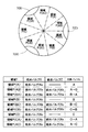
すなわち図6に示す中央制御部31は、図9のパラメータ表に記載された通り、給水バルブX、給水バルブZを開口させるようにしている。ここで本実施形態では、アンバランス位置の特定を、図9に示すように9等分することにより、アンバランス位置(N)の解消に要するバランサたるバッフルを一つに特定するアンバランス位置(N)と、アンバランス位置(N)の解消に要するバランサを二つに特定するアンバランス位置(N)とに場合分けしている。
That is, the
すなわち、アンバランス位置(N)の解消に要するバッフルを一つに特定するアンバランス位置(N)の領域Yとは、領域(P(A))、(P(B))及び(P(C))である。また、アンバランス位置(N)の解消に要するアンバランス位置(N)の領域Yとは、領域(P(AB))、(P(BA))、(P(BC))、(P(CB))、(P(CA))及び(P(AC))である。なおこれら6つの領域の標記について、ABCの何れか二つを標記している箇所の記載順序は、そのまま注水装置1cによって注水するバッフルの順序に相当する。
In other words, the region Y of the unbalance position (N) that specifies one baffle required to eliminate the unbalance position (N) is the regions (P (A)), (P (B)), and (P (C )). In addition, the region Y of the unbalance position (N) required for eliminating the unbalance position (N) is the regions (P (AB)), (P (BA)), (P (BC)), (P (CB) )), (P (CA)) and (P (AC)). In addition, about the marking of these 6 area | regions, the description order of the location which has marked any two of ABC is equivalent to the order of the baffle which injects water with the
すなわち、これら6つの領域に記載されたABCの文字のうち、最初に記載された文字に相当する給水バルブXに注水されるバッフル7が、第一のバランサに相当し、二つ目に記載された文字に相当する給水バルブZに注水されるバッフル7が、第二のバランサに相当する。
That is, the
加えてABCのうち記載されていない文字に相当するバランサは、他のバランサに相当し、本実施形態ではアンバランス位置(N)に最も近接したバッフル7である。
In addition, a balancer corresponding to a character not described in ABC corresponds to another balancer, and in the present embodiment, is a
換言すれば、第一のバランサに相当するバッフル7は、アンバランス位置(N)に対し最も離間したバッフル7ということとなる。
In other words, the
ここで、本実施形態に係る洗濯機の制御方法は、脱水工程において、洗濯槽1bのアンバランス位置(N)を検出するアンバランス位置検出ステップと、このアンバランス位置検出ステップにより注水を要するバランサたるバッフル7を決定するバランサ選択ステップと、このバランサ選択ステップにより少なくとも二つのバッフル7に注水を要するときに複数のバッフルのうちの給水バルブXによりバッフル7に調整水が注水される第一注水ステップと、この第一注入ステップ中の洗濯槽1bのアンバランス量Mの推移を検出するアンバランス量検出ステップと、このアンバランス量検出ステップにより検出されるアンバランス量Mが上昇に転じたときに調整水の注水を第一のバランサから第二のバランサへ切り替えるべく給水バルブXから給水バルブYに注水が切り替わる注水切り替えステップと、注水バルブYにより調整水がバッフル7に注水される第二注水ステップとを具備することを特徴とする。
Here, the control method of the washing machine according to the present embodiment includes an unbalance position detection step for detecting the unbalance position (N) of the
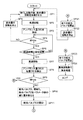
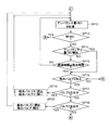
図7,8は、本実施形態の洗濯機1の制御を示すフローチャートである。
7 and 8 are flowcharts showing the control of the
本実施形態では、前記中央制御部31が、図示しない脱水ボタンからの入力信号あるいは洗濯コース運転中に脱水工程を開始すべき旨の信号を受信すると、ステップSP1に進み、脱水工程を開始する。
<ステップSP1>
In the present embodiment, when the
<Step SP1>
ステップSP1では、中央制御部31は、脱水槽2をほぐし反転させた後、脱水槽2の回転を加速させる。
<ステップSP2>
In step SP1, the
<Step SP2>
ステップSP2では、中央制御部31は、低速回転設定値(N1)に基づいて、脱水槽2を低速回転させる。
<ステップSP3>
In step SP2, the
<Step SP3>
ステップSP3では、中央制御部31は、加速度センサ12から与えられた加速度値(加速度センサのx成分)に基づいて、アンバランス量(M)を検出する。
<ステップSP4>
In step SP3, the
<Step SP4>
ステップSP4では、中央制御部31は、アンバランス量(M)と、メモリ32に格納されたアンバランス量設定値(ma)とを比較し、M<maが成り立つか否か判断する。M<maが成り立つと判断すると、ステップSP6に進む。一方、M<maが成り立たないと判断すると、ステップSP5に進む。ここで、アンバランス量設定値(ma)は、バッフル7に調整水を供給しても解消が難しい程度に洗濯物の偏りが大きいことを示す閾値である。すなわち、ステップSP5に進む場合、バッフル7に調整水を供給しても解消が難しい程度に洗濯物の偏りが大きいと判断されたことを意味する。
<ステップSP5>
In step SP4, the
<Step SP5>
ステップSP5では、中央制御部31は、脱水槽2の回転を停止させた後、ステップSP1に戻り、ステップS1〜S4を繰り返す。
<ステップSP6>
In step SP5, the
<Step SP6>
ステップSP6では、中央制御部31は、脱水槽2の低速回転を開始してからの経過時間が、低速回転処理を行う予め定められた設定時間以上であると判断すると、ステップSP7に進む。
<ステップSP7>
In step SP6, when the
<Step SP7>
ステップSP7では、中央制御部31は、高速回転設定値(N2)に基づいて、脱水槽2を高速回転させる。
<ステップSP8>
In step SP7, the
<Step SP8>
ステップSP8では、中央制御部31は、加速度センサ12から与えられた加速度値に基づいて、アンバランス量(M)およびアンバランス位置(N)を検出する。すなわち当該ステップSP8が、本発明に係るアンバランス位置検出ステップに相当する。
<ステップSP9>
In step SP8, the
<Step SP9>
ステップSP9では、中央制御部31は、アンバランス量(M)と、メモリ32に格納された前述のアンバランス量設定値(mb)とを比較し、M<mbが成り立つか否か判断する。M<mbが成り立つと判断すると、後述するステップSP23に進む。一方、M<mbが成り立たないと判断すると、ステップSP10に進む。ここで、アンバランス量設定値(mb)は、アンバランス量設定値(ma)よりも小さい値であり、バッフル7への調整水の供給がなくても騒音が発生しない程度に洗濯物の偏りが小さいことを示す閾値である。すなわち、偏荷重が小さいあるいは存在せず、バッフル7へ給水しなくても騒音が発生しないと判断した場合、ステップSP23に進む。
<ステップSP10>
In step SP9, the
<Step SP10>
ステップSP10では、中央制御部31は、アンバランス位置(N)に基づいて、図9に示す給水バルブX、領域Y,給水バルブZをパラメータ表の値に置き換え、例えばメモリ32に記憶する。すなわち当該ステップSP10が、本発明に係るバランサ選択ステップに相当する。
<ステップSP11>
In step SP10, the
<Step SP11>
ステップSP11では、中央制御部31は、図9のパラメータ表に記載された給水バルブXを開口させる。すなわち当該ステップSP11が、本発明に係る第一注水ステップに相当する。
<ステップSP12>
In step SP11, the
<Step SP12>
図8に示すステップSP12は、中央制御部31は、加速度センサ12から与えられた加速度値に基づいて、アンバランス量(M)を再計算する。すなわち当該ステップSP12が、洗濯槽1bのアンバランス量(M)の推移を検出する本発明に係るアンバランス量検出ステップに相当する。なお当該ステップSP12では通常、アンバランス量(M)によるがはじめのうちは回を重ねるにつれて、アンバランス量(M)は低減していく挙動を示す。
<ステップSP13>
In step SP12 shown in FIG. 8, the
<Step SP13>
ステップSP13では、中央制御部31は、アンバランス量(M)と、メモリ32に格納された前述のアンバランス量設定値(mb)とを比較し、M<mbが成り立つか否か判断する。M<mbが成り立つと判断すると、後述するステップSP23に進む。一方、M<mbが成り立たないと判断すると、ステップSP14に進む。ここで、アンバランス量設定値(mb)は、アンバランス量設定値(ma)よりも小さい値であり、バッフル7への調整水の供給がなくても騒音が発生しない程度に洗濯物の偏りが小さいことを示す閾値である。すなわち、偏荷重が小さいあるいは存在せず、バッフル7へ給水しなくても騒音が発生しないと判断した場合、ステップSP23に進む。
<ステップSP14>
In step SP13, the
<Step SP14>
ステップSP14では、中央制御部31は、ステップ12により検出したアンバランス量(M)が増加に転じていなければ、ステップSP15へ進む。アンバランス量(M)が増加に転じたと判断すると、ステップSP16に進む。
<ステップSP15>
In step SP14, if the unbalance amount (M) detected in
<Step SP15>
ステップSP15では、中央制御部31は、給水バルブXを開口してからの経過時間が、設定時間以上であると判断すると、ステップSP16に進む。上記経過時間が設定時間以下であれば、ステップSP12へ戻る。ここで、当該設定時間は例えば、1つのバッフル7内が調整水でほぼ満水になるまで掛かる時間である。
<ステップSP16>
In step SP15, if the
<Step SP16>
ステップSP16では、中央制御部31は、上記ステップSP12により置き換えられメモリ32に格納されたアンバランス位置(N)が図9のパラメータ表に示す領域Yのうち、どの領域Yであるかを読み出し、アンバランス位置(N)が給水バルブZを設定されていない領域Y、すなわち領域(P(A))、(P(B))又は(P(C))であると判断すると、ステップSP後述するステップSP20に進む。アンバランス位置(N)給水バルブZが設定されている領域Y、すなわち、領域(P(AB))、(P(BA))、(P(BC))、(P(CB))、(P(CA))又は(P(AC))と判断すると、ステップSP17に進む。
<ステップSP17>
In step SP16, the
<Step SP17>
ステップSP17では、中央制御部31は、給水バルブXによる注水中で有るか否かを判断する。給水バルブXによる注水中であれば、ステップSP18へ進む。給水バルブXによる注水中でなければ、ステップSP19へ進む。
<ステップSP18>
In step SP17, the
<Step SP18>
ステップSP18では、図9のパラメータ表に記載された給水バルブXを閉止させるとともに、給水バルブZを開口させる。例えば、当初のアンバランス位置(N)が領域(P(AB))の場合、給水バルブXは、バッフル7(A)に対応した給水バルブ26aになり、給水バルブZは、給水バルブ26aに対応したバッフル7(A)よりも領域(P(AB))に近い位置、換言すれば領域(P(AB))に二番目に遠い位置にあるバッフル7(B)に対応した給水バルブ26bとなる。すなわち当該ステップSP18が、本発明に係る第二注水ステップに相当する。
<ステップSP19>
In step SP18, the water supply valve X described in the parameter table of FIG. 9 is closed and the water supply valve Z is opened. For example, when the initial unbalance position (N) is in the region (P (AB)), the water supply valve X becomes the
<Step SP19>
ステップSP17では、中央制御部31は、給水バルブZによる注水中で有るか否かを判断する。給水バルブZによる注水中であれば、ステップSP20へ進む。給水バルブZによる注水中でなければ、ステップSP後述するステップSP21へ進む。
<ステップSP20>
In step SP17, the
<Step SP20>
ステップSP20では、図9のパラメータ表に記載された給水バルブZを閉止させるとともに、他のバルブを開口させる。例えば、当初のアンバランス位置(N)が領域(P(AB))の場合、給水バルブZは、バッフル7(B)に対応した給水バルブ26bになり、他のバルブは、給水バルブ26bに対応したバッフル7(B)よりも領域(P(AB))に近い位置、換言すれば領域(P(AB))に最も近い位置にあるバッフル7(C)に対応した給水バルブ26cとなる。すなわち当該ステップSP20は、他の注水ステップに相当する。
<ステップSP21>
In step SP20, the water supply valve Z described in the parameter table of FIG. 9 is closed and the other valves are opened. For example, when the initial unbalance position (N) is in the region (P (AB)), the water supply valve Z becomes the
<Step SP21>
図7に示すステップSP21では、中央制御部31は、全ての給水バルブX,Zを閉状態にさせる。
<ステップSP22>
In step SP21 shown in FIG. 7, the
<Step SP22>
ステップSP22では、中央制御部31は、脱水槽2の回転を停止させた後、ステップSP1に戻る。
In step SP22, the
このように、バッフル7への給水では解消しないほど偏荷重が大きいと判断した場合、ステップSP21,22の処理を行って、脱水処理を最初からやり直す。
<ステップSP23>
In this way, when it is determined that the unbalanced load is so large that it cannot be eliminated by water supply to the
<Step SP23>
図8に示すステップSP23では、中央制御部31は、中央制御部31は、全ての給水バルブX,Zを閉状態にさせる。
<ステップSP24>
In step SP23 shown in FIG. 8, the
<Step SP24>
ステップSP24では、中央制御部31は、脱水槽2を最高回転数で所定時間回転させ、脱水処理を行う。その後、脱水処理を終了する。
In step SP24, the
そして図10では、上記ステップSP11からステップSP18を経てステップSP23に至るまでの一連の偏心量の挙動を示している。このように、まず、偏心量すなわちアンバランス量(M)を示す曲線のうち、想像線にて示した部分は、給水バルブXにより注水されるバッフルへの注水が所要量を超えたときの挙動をしめしている。本実施形態では、アンバランス量(M)が立ち上がるタイミングを検知するステップ、当該タイミングにて注水バルブを切り替えるステップSP14を設けることにより、無駄にアンバランス量(M)を増加させてしまう時間を費やすこと無く、速やかに所要のバッフル7への注水を行うことができる。
FIG. 10 shows a series of eccentricity behaviors from step SP11 to step SP23 through step SP18. Thus, first, of the curve indicating the amount of eccentricity, that is, the unbalance amount (M), the portion indicated by the imaginary line is the behavior when the water injection to the baffle injected by the water supply valve X exceeds the required amount. It is showing. In the present embodiment, by providing the step of detecting the timing at which the unbalance amount (M) rises and the step SP14 for switching the water injection valve at the timing, time for increasing the unbalance amount (M) is wasted. Without this, water can be quickly poured into the required
また本実施形態では、第二のバランサへの注水に相当する給水バルブZによる注水によってもアンバランス量(M)がアンバランス量設定値(mb)を下回らない場合、これまで注水を行っていなかった三つ目の給水バルブを開口させるようにしている。このように、本実施形態では複数のバッフル7への注水を行う場合、アンバランス位置(N)から、最も離間しているバッフル7から最も近接したバッフル7へと順に注水を行うようにしている。そしてアンバランス量(M)の上昇が転じるか、或いは所定時間を経過するかの何れかにより、バッフルを切り替えてゆき、これら一連の注水によりアンバランス量(M)がアンバランス量設定値(mb)を下回れば以下に記す運転に移行し、下回らなければ、換言すればステップSP19によりNOとなれば、再び脱水工程のはじめからやり直すようにしている。
Moreover, in this embodiment, if the unbalance amount (M) does not fall below the unbalance amount set value (mb) even by water injection by the water supply valve Z corresponding to water injection to the second balancer, water injection has not been performed so far. The third water supply valve is opened. Thus, in this embodiment, when water is poured into the plurality of
しかる後、アンバランス量(M)が設定値以下になると、脱水槽2を高速脱水回転まで加速し、脱水を行う。そして、脱水が終了して脱水槽2の減速が始まり、遠心力が重力加速度を下回ると、バッフル7内の調整水が開口部71より下部に流れ出し、排水される。
Thereafter, when the unbalance amount (M) becomes equal to or less than the set value, the
上記の制御方法による脱水工程の流れによれば、複数のバッフル7に注水を要する場合でも無駄なく速やかにアンバランス状態を解消するようにしたので、脱水運転の開始から終了までのどの過程においても振動や騒音の発生を防止するのみならず、運転時間の遅延を有効に回避することができる洗濯機1とすることができる。
According to the flow of the dehydration process by the above control method, even when water is required for the plurality of
このように本発明の洗濯機1の制御方法は、脱水工程において、最初に注水を行うバッフル7への注水中にアンバランス量(M)が上昇するというステップSP14のタイミングで次のバッフル7への注水へ切り替えるように制御するので、複数のバランサに注水を要するときであっても注水に要する時間をアンバランスの解消に適したものとすることができる。特に第一のバランサたるバッフル7への注水時間が不要に増加することを有効に回避せしめている。これによりアンバランスの解消に要する時間が必要以上に長期化することを回避し、脱水工程を円滑に行わせている。
Thus, in the control method of the
すなわち本実施形態によれば、脱水工程にて脱水槽2内で洗濯物の偏在があっても回転を減速あるいは停止することなく洗濯槽1bにおける脱水槽2のアンバランスを解消して、脱水槽2の偏心による振動や騒音の発生を抑制し、且つ運転時間の遅延を有効に回避することができる。その結果、使用者が洗濯に要する時間が遅延しないため、使用者の時間の有効利用やコインランドリー店舗の回転効率の向上にも寄与できるものとなっている。
That is, according to the present embodiment, even if the laundry is unevenly distributed in the
また、第一のバランサである給水バルブXにより給水されるバッフル7が、アンバランス位置(N)から最も大きく離間した位置にあるバッフル7であるようにしているので、アンバランス量(M)の低減に最も資するバッフル7に注水することでアンバランス量(M)を速やかに減少させつつ注水切り替えステップであるステップSP18によって必要十分な時間だけ注水させ得るため、より速やかなアンバランスの解消を実現している。
Moreover, since the
また本実施形態では、ステップSP14によるアンバランス量(M)の上昇が検出されなくとも、上述のようなステップSP15すなわち時間切り替えステップを設けているため、第一のバランサたる給水バルブXに注水されるバッフル7への注水がアンバランスの解消度合いが、実際には低いようなときであっても、必要以上に注水が長期化することを回避して、更なるアンバランスの解消に寄与せしめている。
Further, in this embodiment, even if the increase in the unbalance amount (M) due to step SP14 is not detected, since the above-described step SP15, that is, the time switching step is provided, water is injected into the water supply valve X serving as the first balancer. Even if the water injection to the
また本実施形態では、バランサとして、もともと洗濯機1に搭載される洗濯物を攪拌するためのバッフル7を利用しているので、既存の構成を有効に利用することで装置の大型化を回避するのみならず、製造に要する部品点数の増加を有効に回避し、より効率の高い製造にも寄与している。
Moreover, in this embodiment, since the
また本実施形態では、バランサたる複数のバッフル7が脱水槽2の内周面2a1上に等角度間隔で設けられているので、アンバランス位置(N)の特定から給水バルブXの特定までの制御をよりシンプルなものとしつつ、効率の高いアンバランスの解消を実現している。
Moreover, in this embodiment, since the
以上、本発明の一実施形態について説明したが、本実施形態の構成は上述したものに限定されず、種々の変形が可能である。 As mentioned above, although one Embodiment of this invention was described, the structure of this embodiment is not limited to what was mentioned above, A various deformation | transformation is possible.
例えば、上記実施形態では洗濯機として、所謂縦型全自動洗濯機に本発明を適用した一例を開示したが勿論、家庭用の斜めドラム型の全自動洗濯機やコインランドリー店舗にて広く好適に適用されている横型の洗濯乾燥機であっても、本発明に係る制御方法は好適に適用され得る。 For example, in the above-described embodiment, an example in which the present invention is applied to a so-called vertical type fully automatic washing machine is disclosed as a washing machine, but of course, it is widely and suitably applied to an oblique drum type fully automatic washing machine for home use and a coin laundry store. The control method according to the present invention can be preferably applied even to a horizontal washer / dryer.
また例えば、上記実施形態では受水リングユニット5が3つの導水樋5a、5b、5cで構成され、それに対応して3つのバッフル7が設けられるが、これに限らず、バッフル7が3個以上設けられ、かつ導水樋がバッフル7と同数設けられる構成であればよい。
Further, for example, in the above-described embodiment, the water
また、受水リングユニット5は、複数の導水樋5a、5b、5cが上下方向に重層されてなる構成であってもよく、これにより、受水リングユニット5の横幅を狭くして、脱水槽2の開口を広げることができる。
In addition, the water
さらに、バッフル7は、洗濯機1の動作(状況)に応じて、上広がり、或いは下広がりの形状であってもよい。
Further, the
その他の構成も、本発明の趣旨を逸脱しない範囲で種々変形が可能である。 Other configurations can be variously modified without departing from the spirit of the present invention.
1・・・洗濯機
1b・・・洗濯槽
1c・・・注水装置
2a1・・・(洗濯槽の)内周面
7・・・バランサ(バッフル)
S1・・・軸線
SP8・・・アンバランス位置検出ステップ
SP10・・・バランサ選択ステップ
SP11・・・第一注水ステップ
SP14、SP16、SP17、SP18・・・注水切り替えステップ
SP15、SP16、SP17、SP18・・・時間切り替えステップ
SP18・・・第二注水ステップ
DESCRIPTION OF
S1 ... axis line SP8 ... unbalance position detection step SP10 ... balancer selection step SP11 ... first water injection step SP14, SP16, SP17, SP18 ... water injection switching step SP15, SP16, SP17, SP18 ..Time switching step SP18 ... Second water injection step
Claims (5)
前記バランサの各々に個別に調整水を注水する注水装置とを備えてなる洗濯機の制御方法であって、
脱水工程において、
前記洗濯槽のアンバランス位置を検出するアンバランス位置検出ステップと、
このアンバランス位置検出ステップにより注水を要する前記バランサを決定するバランサ選択ステップと、
このバランサ選択ステップにより少なくとも二つの前記バランサに注水を要するときに複数のバランサのうちの任意の第一のバランサに前記調整水を注水する第一注水ステップと、
この第一注入ステップ中の前記洗濯槽のアンバランス量の推移を検出するアンバランス量検出ステップと、
このアンバランス量検出ステップにより検出されるアンバランス量が上昇に転じたときに前記調整水の注水を前記第一のバランサから第二のバランサへ切り替える注水切り替えステップと、
前記第二バランサへ前記調整水を注水する第二注水ステップと
を具備することを特徴とする洗濯機の制御方法。 A hollow balancer disposed on the inner circumferential surface of the washing tub with three or more angular phases around the axis,
A control method for a washing machine comprising a water injection device for individually supplying adjustment water to each of the balancers,
In the dehydration process,
An unbalance position detecting step for detecting an unbalance position of the washing tub;
A balancer selection step for determining the balancer requiring water injection by the unbalance position detection step;
A first water injection step of injecting the adjusted water to an arbitrary first balancer among a plurality of balancers when water is required for at least two of the balancers by the balancer selection step;
An unbalance amount detection step of detecting a transition of the unbalance amount of the washing tub during the first injection step;
A water injection switching step for switching the water injection of the adjusted water from the first balancer to the second balancer when the unbalance amount detected by the unbalance amount detection step starts to increase,
A second water injection step of injecting the adjusted water into the second balancer.
Priority Applications (5)
| Application Number | Priority Date | Filing Date | Title |
|---|---|---|---|
| JP2015251163A JP2017113232A (en) | 2015-12-24 | 2015-12-24 | Washing machine control method |
| PCT/CN2016/111802 WO2017107989A1 (en) | 2015-12-24 | 2016-12-23 | Method of controlling washing machine |
| US16/065,786 US10619285B2 (en) | 2015-12-24 | 2016-12-23 | Control method of washing machine |
| EP16877799.3A EP3396043B1 (en) | 2015-12-24 | 2016-12-23 | Method of controlling a washing machine |
| CN201680075501.3A CN108431320B (en) | 2015-12-24 | 2016-12-23 | Control method of washing machine |
Applications Claiming Priority (1)
| Application Number | Priority Date | Filing Date | Title |
|---|---|---|---|
| JP2015251163A JP2017113232A (en) | 2015-12-24 | 2015-12-24 | Washing machine control method |
Publications (1)
| Publication Number | Publication Date |
|---|---|
| JP2017113232A true JP2017113232A (en) | 2017-06-29 |
Family
ID=59089174
Family Applications (1)
| Application Number | Title | Priority Date | Filing Date |
|---|---|---|---|
| JP2015251163A Pending JP2017113232A (en) | 2015-12-24 | 2015-12-24 | Washing machine control method |
Country Status (5)
| Country | Link |
|---|---|
| US (1) | US10619285B2 (en) |
| EP (1) | EP3396043B1 (en) |
| JP (1) | JP2017113232A (en) |
| CN (1) | CN108431320B (en) |
| WO (1) | WO2017107989A1 (en) |
Cited By (4)
| Publication number | Priority date | Publication date | Assignee | Title |
|---|---|---|---|---|
| WO2019100696A1 (en) * | 2017-11-21 | 2019-05-31 | 青岛海尔洗衣机有限公司 | Drum-type washing machine |
| JP2022010783A (en) * | 2020-06-29 | 2022-01-17 | 青島海爾洗衣机有限公司 | washing machine |
| JP2022010785A (en) * | 2020-06-29 | 2022-01-17 | 青島海爾洗衣机有限公司 | washing machine |
| JP2022158569A (en) * | 2021-04-02 | 2022-10-17 | 東芝ライフスタイル株式会社 | washing machine |
Families Citing this family (9)
| Publication number | Priority date | Publication date | Assignee | Title |
|---|---|---|---|---|
| CN113005716B (en) * | 2019-12-18 | 2023-01-17 | 广东美的白色家电技术创新中心有限公司 | Washing device, control method thereof, and readable storage medium |
| KR102824479B1 (en) * | 2019-12-20 | 2025-06-24 | 엘지전자 주식회사 | Controlling Method of Laundry Treatment Apparatus |
| JP7527560B2 (en) * | 2020-06-29 | 2024-08-05 | 青島海爾洗衣机有限公司 | washing machine |
| CN114318777B (en) * | 2020-09-30 | 2023-02-17 | 无锡小天鹅电器有限公司 | Balancing device, barrel assembly and clothes treatment equipment |
| CN114318767B (en) * | 2020-09-30 | 2023-02-24 | 无锡小天鹅电器有限公司 | Clothes treatment equipment and control method thereof |
| JP7589917B2 (en) * | 2021-04-26 | 2024-11-26 | 青島海爾洗衣机有限公司 | washing machine |
| JP2023035692A (en) * | 2021-09-01 | 2023-03-13 | 青島海爾洗衣机有限公司 | washing machine |
| JP2023035691A (en) * | 2021-09-01 | 2023-03-13 | 青島海爾洗衣机有限公司 | washing machine |
| CN117298712B (en) * | 2023-10-27 | 2024-07-26 | 深圳市汉斯顿净水设备有限公司 | Rotary filter element capable of keeping high rotation speed stability |
Family Cites Families (22)
| Publication number | Priority date | Publication date | Assignee | Title |
|---|---|---|---|---|
| US2534269A (en) * | 1948-05-26 | 1950-12-19 | Kahn | Automatic balancing system for cleaning machine cylinders |
| US3610069A (en) * | 1969-11-14 | 1971-10-05 | Arundale Mfg Inc | Molded one-piece balancing ring |
| US5280660A (en) * | 1992-10-05 | 1994-01-25 | Pellerin Milnor Corporation | Centrifugal extracting machine having balancing system |
| JP2954031B2 (en) * | 1995-08-28 | 1999-09-27 | 三星電子株式会社 | Washing machine balance |
| JP3332769B2 (en) | 1996-02-27 | 2002-10-07 | 三洋電機株式会社 | Centrifugal dewatering device |
| JP2901913B2 (en) * | 1996-03-12 | 1999-06-07 | 株式会社東芝 | Dewatering tank balancer |
| JPH1024186A (en) | 1996-07-10 | 1998-01-27 | Sanyo Electric Co Ltd | Drum type washing machine |
| JP3188209B2 (en) | 1997-03-21 | 2001-07-16 | 三洋電機株式会社 | Centrifugal dehydrator |
| US5829084A (en) * | 1997-06-02 | 1998-11-03 | Fujiwara; Leslie H. | Method and system for balancing an upright washing machine |
| JP2001062185A (en) | 1999-08-30 | 2001-03-13 | Sanyo Electric Co Ltd | Drum type washing machine |
| PL1736589T3 (en) * | 2005-06-24 | 2015-03-31 | V Zug Ag | Washing machine with unbalance detector |
| US8695381B2 (en) * | 2008-03-28 | 2014-04-15 | Electrolux Home Products, Inc. | Laundering device vibration control |
| KR20110057302A (en) * | 2009-11-24 | 2011-06-01 | 삼성전자주식회사 | Fluid balancer and washing machine with it |
| KR101370421B1 (en) | 2009-12-31 | 2014-03-25 | 아세릭 에이. 에스 | A washing machine wherein the unbalanced load is balanced |
| JP5650927B2 (en) | 2010-05-20 | 2015-01-07 | ハイアール グループ コーポレーション | Washing machine |
| WO2011144559A1 (en) * | 2010-05-20 | 2011-11-24 | Arcelik Anonim Sirketi | A washing machine wherein the unbalanced load is balanced |
| US9003838B2 (en) * | 2010-12-08 | 2015-04-14 | Whirlpool Corporation | Laundry treating appliance with balancing system |
| US8713977B2 (en) * | 2010-12-08 | 2014-05-06 | Whirlpool Corporation | Laundry treating appliance with balancing system |
| US8991223B2 (en) * | 2010-12-08 | 2015-03-31 | Whirlpool Corporation | Laundry treating appliance with balancing system |
| CN102560965B (en) | 2012-01-17 | 2014-02-05 | 江苏海狮机械集团有限公司 | Roller balancing device for full-automatic washer extractor |
| KR102032845B1 (en) | 2013-02-13 | 2019-10-16 | 엘지전자 주식회사 | Laundry Treating Apparatus |
| JP6608659B2 (en) * | 2015-09-17 | 2019-11-20 | 青島海爾洗衣机有限公司 | Washing machine and control method of washing machine |
-
2015
- 2015-12-24 JP JP2015251163A patent/JP2017113232A/en active Pending
-
2016
- 2016-12-23 US US16/065,786 patent/US10619285B2/en active Active
- 2016-12-23 EP EP16877799.3A patent/EP3396043B1/en active Active
- 2016-12-23 WO PCT/CN2016/111802 patent/WO2017107989A1/en not_active Ceased
- 2016-12-23 CN CN201680075501.3A patent/CN108431320B/en active Active
Cited By (9)
| Publication number | Priority date | Publication date | Assignee | Title |
|---|---|---|---|---|
| WO2019100696A1 (en) * | 2017-11-21 | 2019-05-31 | 青岛海尔洗衣机有限公司 | Drum-type washing machine |
| CN111386366A (en) * | 2017-11-21 | 2020-07-07 | 青岛海尔洗衣机有限公司 | Drum type washing machine |
| CN111386366B (en) * | 2017-11-21 | 2022-08-19 | 青岛海尔洗衣机有限公司 | Drum type washing machine |
| JP2022010783A (en) * | 2020-06-29 | 2022-01-17 | 青島海爾洗衣机有限公司 | washing machine |
| JP2022010785A (en) * | 2020-06-29 | 2022-01-17 | 青島海爾洗衣机有限公司 | washing machine |
| JP7482479B2 (en) | 2020-06-29 | 2024-05-14 | 青島海爾洗衣机有限公司 | washing machine |
| JP7503266B2 (en) | 2020-06-29 | 2024-06-20 | 青島海爾洗衣机有限公司 | washing machine |
| JP2022158569A (en) * | 2021-04-02 | 2022-10-17 | 東芝ライフスタイル株式会社 | washing machine |
| JP7556816B2 (en) | 2021-04-02 | 2024-09-26 | 東芝ライフスタイル株式会社 | washing machine |
Also Published As
| Publication number | Publication date |
|---|---|
| WO2017107989A1 (en) | 2017-06-29 |
| US20190003100A1 (en) | 2019-01-03 |
| CN108431320A (en) | 2018-08-21 |
| EP3396043A4 (en) | 2019-01-09 |
| US10619285B2 (en) | 2020-04-14 |
| CN108431320B (en) | 2021-03-02 |
| EP3396043A1 (en) | 2018-10-31 |
| EP3396043B1 (en) | 2021-05-19 |
Similar Documents
| Publication | Publication Date | Title |
|---|---|---|
| JP6608659B2 (en) | Washing machine and control method of washing machine | |
| JP2017113232A (en) | Washing machine control method | |
| KR101986243B1 (en) | washer | |
| CN105839336B (en) | The control method of washing machine | |
| JP6736807B2 (en) | Washing machine | |
| JP2012170686A (en) | Drum-type washing machine | |
| WO2016180371A1 (en) | Washing machine | |
| KR20220021717A (en) | Clothes Treating Apparatus and Controlling Method thereof | |
| KR102328248B1 (en) | Washing machine with ball balancer and vibration reduction method thereof | |
| JP2011224227A (en) | Washing machine | |
| JP7093069B2 (en) | washing machine | |
| CN114729489B (en) | Washing machine | |
| JP7369398B2 (en) | washing machine | |
| KR20220021710A (en) | Clothes Treating Apparatus and Controlling Method thereof | |
| JP6553448B2 (en) | Drum type washing machine | |
| JP7503266B2 (en) | washing machine | |
| JP7527560B2 (en) | washing machine | |
| KR20230172686A (en) | Washing apparutus and controlling method thereof | |
| KR20120109171A (en) | Method for controlling dehydration in drum type washing machine | |
| KR20120109172A (en) | Method for controlling dehydration in drum type washing machine | |
| KR20160034636A (en) | Washing machine and washing method using the same |