JP2017113708A - Rice milling facility - Google Patents
Rice milling facility Download PDFInfo
- Publication number
- JP2017113708A JP2017113708A JP2015252306A JP2015252306A JP2017113708A JP 2017113708 A JP2017113708 A JP 2017113708A JP 2015252306 A JP2015252306 A JP 2015252306A JP 2015252306 A JP2015252306 A JP 2015252306A JP 2017113708 A JP2017113708 A JP 2017113708A
- Authority
- JP
- Japan
- Prior art keywords
- roof
- signboard
- building
- rice milling
- rainwater
- Prior art date
- Legal status (The legal status is an assumption and is not a legal conclusion. Google has not performed a legal analysis and makes no representation as to the accuracy of the status listed.)
- Granted
Links
- 235000007164 Oryza sativa Nutrition 0.000 title claims abstract description 42
- 235000009566 rice Nutrition 0.000 title claims abstract description 42
- 238000003801 milling Methods 0.000 title claims abstract description 34
- 240000007594 Oryza sativa Species 0.000 title 1
- 241000209094 Oryza Species 0.000 claims abstract description 41
- 238000005192 partition Methods 0.000 claims abstract description 8
- 235000021329 brown rice Nutrition 0.000 description 6
- 239000004575 stone Substances 0.000 description 5
- 230000003014 reinforcing effect Effects 0.000 description 4
- 238000000034 method Methods 0.000 description 3
- 230000000694 effects Effects 0.000 description 2
- 230000002087 whitening effect Effects 0.000 description 2
- 238000005260 corrosion Methods 0.000 description 1
- 230000007797 corrosion Effects 0.000 description 1
- 238000005034 decoration Methods 0.000 description 1
- 238000009423 ventilation Methods 0.000 description 1
- XLYOFNOQVPJJNP-UHFFFAOYSA-N water Substances O XLYOFNOQVPJJNP-UHFFFAOYSA-N 0.000 description 1
Images





Landscapes
- Adjustment And Processing Of Grains (AREA)
Abstract
【課題】屋外に設置される建屋の存在を目立たせ、不特定の人に認識し易く、また、雨水の処理がし易い建屋式の精米設備を提供すること。【解決手段】建屋の内部を前側の客室扉のある客室と後側の機械室に仕切壁で仕切り、鉛直方向の断面がコ型状又は折れ曲がり状に形成した屋根を建屋の前側から後側に向かって下がり傾斜状とし、屋根の前端部に屋根よりも上方に位置する前看板K1を取り付け、屋根の後端部から設定距離離間した位置に後看板を後看板取付部を介して取り付けた精米設備であり、前看板K1が屋根より上方に突出するため、建屋の外観が目立ち易く、後看板により建屋の後方からも建屋の存在を目立たせることができ、また、屋根上の雨水が後側に流れるので、客室側に出入りする利用者に雨水がかかるのを防止できる。また、屋根の後端部から排出される雨水が後看板に当接して落下排水できるので屋根上の雨水の排水が良好になる。【選択図】図10An object of the present invention is to provide a building-type rice milling facility that makes the presence of a building installed outdoors, easily recognized by an unspecified person, and easy to treat rainwater. SOLUTION: The interior of a building is divided into a guest room with a front passenger door and a machine room on the rear side by a partition wall, and a roof whose vertical section is formed in a U shape or a bent shape is formed from the front side to the rear side of the building. A rice mill that is inclined downward and has a front signboard K1 positioned above the roof at the front end of the roof, and a rear signboard attached via a rear signboard mounting section at a set distance from the rear end of the roof. Because the front signboard K1 protrudes upward from the roof, the appearance of the building is conspicuous, and the presence of the building can be conspicuous from the back of the building by the rear signboard. Therefore, it is possible to prevent rainwater from entering and leaving the guest room. In addition, rainwater discharged from the rear end of the roof comes into contact with the rear signboard and can be dropped and drained, so that drainage of rainwater on the roof is improved. [Selection] Figure 10
Description
本発明は、不特定多数の利用者が利用する建屋式の精米設備に関する。 The present invention relates to a building-type rice milling facility used by an unspecified number of users.
特許文献1には、上記建屋式の精米設備が記載されている。
特許4525445号 Japanese Patent No. 45525445
上記特許文献記載の建屋式の精米設備は、簡易な構成の建屋により、受入スペースの多様な使用によって幅広い様態に対応することが出来る構成であるが、堅牢度、外観などには改善の余地があった。 The building-type rice milling equipment described in the above-mentioned patent document is a structure that can handle a wide variety of aspects by using the receiving space in a variety of ways, but there is room for improvement in robustness, appearance, etc. there were.
本発明の課題は、屋外に設置される建屋の存在を目立たせ、不特定の人に認識し易く、また、雨水の処理がし易い建屋式の精米設備を提供することである。 An object of the present invention is to provide a building-type rice milling facility that makes the presence of a building installed outdoors, easily recognized by an unspecified person, and easy to treat rainwater.
上記課題を解決するために、本発明は次の解決手段を採用した。
請求項1記載の発明は、柱(26,27など)に平板状の床部(36,37)と側壁部と屋根(24)を組み付けて建屋(1)とし、建屋(1)の内部を前側の客室(3)と後側の機械室(4)に仕切る仕切壁(2)を設け、客室(3)の前側には利用者が出入りする利用者用出入り扉(21)を設け、建屋(1)の屋根(24)を前側から後側に向かって下がり傾斜状とし、屋根(24)の前端部に屋根(24)よりも上方に上端部が位置する前看板(K1)を取り付ける前看板取り付け部(40)を、屋根(24)より上方に突出して設け、屋根(24)の後端部から設定距離離間した位置に後看板(K3)を設け、後看板(K3)を支持する後看板取付部(42)を建屋(1)の背面に取り付けることを特徴とする建屋式の精米設備である。
In order to solve the above problems, the present invention employs the following means.
The invention according to
請求項2記載の発明は、後看板(K3)は屋根(24)の略左右幅全体にわたって延びる構成とし、後看板取付部(42)を取り付けるための左右の後柱部(27)を設け、後看板取付部(42)は鉛直方向の断面がコ型状又は折れ曲がり状に形成し、少なくとも後看板(K3)の左右両側部を支持する構成とすることを特徴とする請求項1記載の建屋式の精米設備である。
In the invention according to
請求項3記載の発明は、後看板(K3)の上端部を屋根(24)の後端部より高い位置に設け、下端部を屋根(24)の後端部より低い位置に設け、後壁(19)と対向することを特徴とする請求項1又は2記載の建屋式の精米設備である。
In the invention according to
本発明の請求項1記載の構成より、前看板(K1)が屋根(24)より上方に突出するため、建屋(1)の外観を目立たせ易く、また、後看板(K3)により、建屋(1)の後方からも建屋(1)の存在を目立たせることができる。また、屋根(24)上の雨水が建屋(1)の後側に流れるので、客室(3)側に出入りする利用者に雨水がかかるのを防止できる。また、屋根(24)の後端部から排出される雨水が後看板(K3)に当接して落下排水できるので屋根上の雨水の排水が良好になる。 Since the front signboard (K1) protrudes upward from the roof (24), the exterior of the building (1) is easily noticeable, and the rear signboard (K3) The presence of the building (1) can also be conspicuous from the back of 1). Further, since rainwater on the roof (24) flows to the rear side of the building (1), it is possible to prevent rainwater from being applied to the user entering and exiting the cabin (3) side. In addition, rainwater discharged from the rear end portion of the roof (24) abuts on the rear sign (K3) and can be dropped and drained, so that drainage of rainwater on the roof is improved.
また、請求項2記載の発明により、請求項1記載の発明の効果に加えて、屋根(24)全体から排水される雨水が後看板(K3)に当接して落下排水できるため、雨水の排水が良好になる。
Further, according to the invention of
さらに、請求項3記載の発明により、請求項1又は請求項2記載の発明の効果に加えて、屋根(24)から排水される雨水を確実に下方に落下排水することができる。
Furthermore, according to the invention of
本発明の実施の形態の建屋式の精米設備について、以下説明する。
本実施の形態の精米設備では、図2に示すように、建屋1は、仕切壁2により、利用者が出入りする客室3と装置各部を配置する機械室4に仕切られている。
The building-type rice milling equipment according to the embodiment of the present invention will be described below.
In the rice milling facility of the present embodiment, as shown in FIG. 2, the
客室3側には、利用者が持参した玄米を機械室4側に配置された投入ホッパ5に投入する投入口を開閉する昇降式の開閉扉6と、利用者が精白度を選択する精白度選択スイッチ7と、料金投入口8と、釣銭返却口9と、精米運転の状況を表示する表示画面10と、精米処理された精白米を収容する白米タンク11を設ける。
On the side of the
図2又は図3に示すように、機械室4側には、投入ホッパ5内に投入された玄米を繰り出すロータリバルブ12と、玄米に混じる石を除去する石抜機13と、石抜きされた玄米を精米処理する精米機14を備える。また、ロータリバルブ12で繰り出された玄米を石抜機13に供給する第一昇降機15と、石抜機13で石抜き処理された玄米を精米機14に供給する第二昇降機16を設ける。また、精米機14で精米処理された精白米を収容する白米タンク11を備えている。
As shown in FIG. 2 or 3, on the machine room 4 side, a
次に建屋1の外観について説明する。
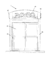
図4又は図5に示すように、建屋1の正面には、利用者が客室3を出入りするための客室扉21を備えた建屋正面に設け、建屋1の側壁22には管理者が機械室2を出入りするための機械室扉23を設けている。建屋1の屋根24(図7)は客室扉21より前側に突出し、屋根24の前端部は屋根24よりも上方に延びる軒部25(図10)を形成し、軒部25の前側は前看板K1を設ける。
Next, the external appearance of the
As shown in FIG. 4 or FIG. 5, the front of the
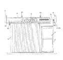
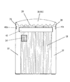
図5に示すように、建屋1の側壁22の上側には横看板K2を設け、屋根24の後端部から設定距離離間する位置に後看板K3を設ける。後看板K3の下端部は屋根24よりも下方に位置して後壁19(図7)と対向し、後看板K3の上端は屋根24よりも上方に位置する(図12)。
As shown in FIG. 5, a horizontal signboard K <b> 2 is provided on the upper side of the
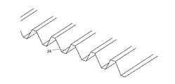
屋根24は図15に示すように連続する凹凸状を折板状に形成し、その前端部を軒部25の背面に接続し、その後端部は建屋1の後壁19より後方まで延びている。そして、屋根24の前端部から後端部に向かって後斜め下がり姿勢に構成している。
As shown in FIG. 15, the
次に建屋1の柱構成について説明する。
図4と図5と図10に示すように、左右一対の前柱26及び後柱27を設け、前柱26の上端部と後柱27の上端部を前後方向に延びる左右一対の上柱28でそれぞれ連結する。上柱28は、前柱26より前方に突出し、その前端部を軒部25の背面に連結している。また、前柱26の下端部と後柱27の下端部を前後方向に延びる左右一対の下柱29でそれぞれ連結する。
Next, the column configuration of the
As shown in FIGS. 4, 5, and 10, a pair of left and right
左右一対の上柱28の中間部と下柱29の中間部を一対の第一中間上下フレーム30及び一対の第二中間上下フレーム31の両端にそれぞれ連結する。左右の上柱28の後端部同士を後左右フレーム20で連結する。左右の上柱28の中間部を第一中間左右フレーム33と第二中間左右フレーム34と第三中間左右フレーム35の両端にそれぞれ連結する。また、一対の第一中間上下フレーム30の上端と第一中間左右フレーム33の両端をそれぞれ連結し、機械室4内の略前後方向の中間部を正面視で門構えに構成している。
The middle part of the pair of left and right
第二中間上下フレーム31の上端と第二中間左右フレーム34の両端をそれぞれ連結し、正面視で門構えに構成し、仕切壁2の外周を支持する構成とする。また、第三中間左右フレーム35の両端を前柱26の上端に連結し、正面視で門構えに構成している。
The upper end of the second intermediate upper and
図10に示すように、一対の下柱29の間には機械室床36と客室床37が配置される。また、第一中間上下フレーム30と第二中間上下フレーム31の間、及び第二中間上下フレーム31と前柱26の間等には補強フレームhが取り付けられる。図10に示す補強フレームh以外にも適宜の箇所に設けられるが、全ての補強フレームhについての説明は省略する。
As shown in FIG. 10, a
次に看板K1、K2、K3の取り付け構造について説明する。
前看板K1を取り付ける軒部25は図10に示すように平面視でコ型に形成され、軒部25の左右後部25aを前柱26の前面に取り付ける構成である。軒部25の前面部分25bに前看板取付プレート40を取りつける。本実施の形態の前看板K1は電飾看板であり、前看板取付プレート40には電飾用の部材41を取り付けている。前看板K1は軒部25の左右幅略全体にわたって覆う構成とし、その上部をアーチ状に形成している。前看板取付プレート40及び軒部25の前面部分25bも前看板K1の形状に沿う形状に形成している。
Next, the attachment structure of the signboards K1, K2, and K3 will be described.
The
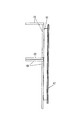
後看板K3は、左右の後柱27からそれぞれ後方に突出する後看板取付プレート42で支持されている。図6に示すように、後看板取付プレート42は左右の後柱27にそれぞれ取り付ける基部42aと、後方に突出する突出部42bと、突出部42bの後端から左右方向に延びる後看板取り付け部42cで構成されている。
The rear signboard K3 is supported by rear
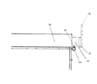
図5、図12及び図13に示すように、後看板K3の上端部は屋根24より高い位置にあり、後看板K3の下端部は屋根24より低い後壁19と対向する位置にある。そして、後看板K3の背面と屋根24の後端部は後看板取付プレート42を介して互いに離間して対向する構成としている。後看板K3の左右方向は屋根24と略同じ幅に形成している。
As shown in FIGS. 5, 12, and 13, the upper end portion of the rear signboard K <b> 3 is at a position higher than the
図10に示すように、前柱26と第一中間上下フレーム30の間に亘って前後方向に延びる第二上柱50を上柱28の下部に取り付ける。また、図9に示すように、横看板K2を取り付ける横看板用取付フレーム51を上柱28の外側面と第二上柱50の外側面に亘って、上柱28と第二上柱50を覆うように取り付けている。横看板K2の上端は上柱28の上端面と面位置を略合わせている。
As shown in FIG. 10, a second
次に、フック44、45の取り付け構成について説明する。
吊上げ用フック44(44a、44b)を上柱28の上面部に前後方向に複数取り付けている(図5参照)。本実施の形態では上柱28に前後方向に2つ設けており、後吊上げ用フック44aを第一中間左右フレーム33の隣接位置に設け、前吊上げ用フック44bを第二中間左右フレーム34と第三中間左右フレーム35の間の位置に設けている。すなわち、機械室4の前後方向中間位置と、客室3の前後方向中間位置に吊上げ用フック44a、44bを設けており、建屋1の輸送時にトラックの荷台への積み下ろし時にクレーン等(図示せず)で吊り上げる際に前後バランスが良好であり、積み下ろし作業がし易い。
Next, the attachment structure of the hooks 44 and 45 will be described.
A plurality of lifting hooks 44 (44a, 44b) are attached to the upper surface of the
また、本実施の形態の固定用フック45(45a、45b)は前後方向に2つ設けており、前固定用フック45aは軒部25の左右後部25aの下面部に設け(図5参照)、後固定用フック45bは上柱28の後端部の下面部に設け(図5、図7参照)ている。
Further, two fixing hooks 45 (45a, 45b) of the present embodiment are provided in the front-rear direction, and the
そのため、トラックの荷台(図示せず)に建屋1を搭載し、運搬するときに、ロープを固定用フック45に掛けて前後から荷台に固定できるので、安全にトラックで運搬できる。また、図14に示すように、固定用フック45はナット等の締結具46で着脱可能に構成することで、建屋1を目的まで運搬した後は固定用フック45を外すことで、建屋の外観を良好にすることができる。
Therefore, when the
以下、本実施の形態の精米設備の建屋1の特徴について述べる。
屋根24に降った雨水は、後傾斜姿勢の屋根24に沿って、後方に流れる。そして、屋根24の後端部から排出された雨水は、後看板K3又は後看板取付プレート42に当接して、下方に落下排水される。
Hereinafter, the characteristics of the
Rainwater that has fallen on the
そのため、雨水を確実に落下排水することができ、建屋1に隣接する他の建屋や構造物に雨水がかかり難い。また、屋根24の後端部は建屋1の後壁19より後方に位置するため、後壁19に雨水がかかり難くなり、後壁19の腐食の進行をし難くすることができる。また、後壁19に設けている換気扇54(図7)に雨水がかかり難くすることができる。また、屋根24の前端部は前看板K1を取り付ける軒部25が屋根24よりも上方に突出しているので屋根24に降った雨水が客室3に出入りする利用者にかかるのを防止できる。
Therefore, rainwater can be surely dropped and drained, and it is difficult for rainwater to splash on other buildings and structures adjacent to the
本実施の形態では前看板K1のみが電飾看板であるが、横看板K2と後看板K3を電飾看板にすることが可能である。 In the present embodiment, only the front signboard K1 is an electric signboard, but the horizontal signboard K2 and the rear signboard K3 can be used as an electric signboard.
1 建屋
2 仕切壁
3 客室
4 機械室
19 後壁
21 客室扉
22 側壁
24 屋根
25 軒部
26 前柱
27 後柱
28 上柱
36 機械室床
37 客室床
40 前看板取付けプレート
42 後看板取付けプレート
K1 前看板
K2 横看板
K3 後看板
DESCRIPTION OF
Claims (3)
建屋(1)の内部を前側の客室(3)と後側の機械室(4)に仕切る仕切壁(2)を設け、
客室(3)の前側には利用者が出入りする利用者用出入り扉(21)を設け、
建屋(1)の屋根(24)を前側から後側に向かって下がり傾斜状とし、
屋根(24)の前端部に屋根(24)よりも上方に上端部が位置する前看板(K1)を取り付ける前看板取り付け部(40)を、屋根(24)より上方に突出して設け、
屋根(24)の後端部から設定距離離間した位置に後看板(K3)を設け、
後看板(K3)を支持する後看板取付部(42)を建屋(1)の背面に取り付けることを特徴とする建屋式の精米設備。 A flat floor (36, 37), side wall and roof (24) are assembled to a pillar (26, 27, etc.) to form a building (1).
A partition wall (2) is provided to partition the interior of the building (1) into a front passenger room (3) and a rear machine room (4).
The front door of the guest room (3) is provided with a user entrance door (21) through which the user enters and exits.
The roof (24) of the building (1) is inclined downward from the front side to the rear side,
A front signboard mounting portion (40) for attaching a front signboard (K1) having an upper end located above the roof (24) at the front end of the roof (24) is provided so as to protrude above the roof (24);
A rear signboard (K3) is provided at a position separated from the rear end of the roof (24) by a set distance,
A building-type rice milling facility characterized in that a rear signboard mounting portion (42) for supporting the rear signboard (K3) is attached to the back of the building (1).
後看板取付部(42)を取り付けるための左右の後柱部(27)を設け、
後看板取付部(42)は鉛直方向の断面がコ型状又は折れ曲がり状に形成し、少なくとも後看板(K3)の左右両側部を支持する構成とすることを特徴とする請求項1記載の建屋式の精米設備。 The rear signboard (K3) extends over substantially the entire left and right width of the roof (24),
The left and right rear pillar portions (27) for attaching the rear signboard attachment portion (42) are provided,
The building according to claim 1, wherein the rear signboard mounting portion (42) has a vertical cross section formed in a U-shape or a bent shape and supports at least the left and right sides of the rear signboard (K3). Type rice milling equipment.
Priority Applications (1)
| Application Number | Priority Date | Filing Date | Title |
|---|---|---|---|
| JP2015252306A JP6477460B2 (en) | 2015-12-24 | 2015-12-24 | Rice milling equipment |
Applications Claiming Priority (1)
| Application Number | Priority Date | Filing Date | Title |
|---|---|---|---|
| JP2015252306A JP6477460B2 (en) | 2015-12-24 | 2015-12-24 | Rice milling equipment |
Publications (2)
| Publication Number | Publication Date |
|---|---|
| JP2017113708A true JP2017113708A (en) | 2017-06-29 |
| JP6477460B2 JP6477460B2 (en) | 2019-03-06 |
Family
ID=59232918
Family Applications (1)
| Application Number | Title | Priority Date | Filing Date |
|---|---|---|---|
| JP2015252306A Active JP6477460B2 (en) | 2015-12-24 | 2015-12-24 | Rice milling equipment |
Country Status (1)
| Country | Link |
|---|---|
| JP (1) | JP6477460B2 (en) |
Cited By (1)
| Publication number | Priority date | Publication date | Assignee | Title |
|---|---|---|---|---|
| JP2023118438A (en) * | 2022-02-15 | 2023-08-25 | 井関農機株式会社 | rice milling equipment |
Citations (15)
| Publication number | Priority date | Publication date | Assignee | Title |
|---|---|---|---|---|
| JPS5120601Y2 (en) * | 1972-05-29 | 1976-05-29 | ||
| JPS5418030U (en) * | 1977-07-07 | 1979-02-05 | ||
| GB2173229A (en) * | 1985-04-03 | 1986-10-08 | Portakabin Ltd | Roof structure |
| JPH0329480Y2 (en) * | 1986-04-11 | 1991-06-24 | ||
| JPH0735674B2 (en) * | 1988-03-07 | 1995-04-19 | フランスベッド株式会社 | Simple house |
| JP2001207664A (en) * | 2000-01-31 | 2001-08-03 | Iseki & Co Ltd | Building structure |
| JP2001271503A (en) * | 2000-03-27 | 2001-10-05 | Network Communication:Kk | Simple installation type small-scale shop |
| JP2002309729A (en) * | 2001-04-16 | 2002-10-23 | Idemitsu Kosan Co Ltd | Snow melting water drainage system for roofs in cold regions |
| JP2004183398A (en) * | 2002-12-05 | 2004-07-02 | Nakajima Kogyo:Kk | Mobile store |
| JP2005273228A (en) * | 2004-03-24 | 2005-10-06 | Fuji Heavy Ind Ltd | Unit house |
| JP2006297342A (en) * | 2005-04-25 | 2006-11-02 | Iseki & Co Ltd | Building-type rice milling facility |
| JP2011072871A (en) * | 2009-09-29 | 2011-04-14 | Iseki & Co Ltd | Coin-operated rice polishing machine |
| JP2013006165A (en) * | 2011-06-27 | 2013-01-10 | Iseki & Co Ltd | Coin-operated rice-polishing machine |
| JP2013086009A (en) * | 2011-10-17 | 2013-05-13 | Yamamoto Co Ltd | Automatic rice milling device |
| JP2014150142A (en) * | 2013-01-31 | 2014-08-21 | Panasonic Corp | Photovoltaic device and decorative structure including the same |
-
2015
- 2015-12-24 JP JP2015252306A patent/JP6477460B2/en active Active
Patent Citations (15)
| Publication number | Priority date | Publication date | Assignee | Title |
|---|---|---|---|---|
| JPS5120601Y2 (en) * | 1972-05-29 | 1976-05-29 | ||
| JPS5418030U (en) * | 1977-07-07 | 1979-02-05 | ||
| GB2173229A (en) * | 1985-04-03 | 1986-10-08 | Portakabin Ltd | Roof structure |
| JPH0329480Y2 (en) * | 1986-04-11 | 1991-06-24 | ||
| JPH0735674B2 (en) * | 1988-03-07 | 1995-04-19 | フランスベッド株式会社 | Simple house |
| JP2001207664A (en) * | 2000-01-31 | 2001-08-03 | Iseki & Co Ltd | Building structure |
| JP2001271503A (en) * | 2000-03-27 | 2001-10-05 | Network Communication:Kk | Simple installation type small-scale shop |
| JP2002309729A (en) * | 2001-04-16 | 2002-10-23 | Idemitsu Kosan Co Ltd | Snow melting water drainage system for roofs in cold regions |
| JP2004183398A (en) * | 2002-12-05 | 2004-07-02 | Nakajima Kogyo:Kk | Mobile store |
| JP2005273228A (en) * | 2004-03-24 | 2005-10-06 | Fuji Heavy Ind Ltd | Unit house |
| JP2006297342A (en) * | 2005-04-25 | 2006-11-02 | Iseki & Co Ltd | Building-type rice milling facility |
| JP2011072871A (en) * | 2009-09-29 | 2011-04-14 | Iseki & Co Ltd | Coin-operated rice polishing machine |
| JP2013006165A (en) * | 2011-06-27 | 2013-01-10 | Iseki & Co Ltd | Coin-operated rice-polishing machine |
| JP2013086009A (en) * | 2011-10-17 | 2013-05-13 | Yamamoto Co Ltd | Automatic rice milling device |
| JP2014150142A (en) * | 2013-01-31 | 2014-08-21 | Panasonic Corp | Photovoltaic device and decorative structure including the same |
Cited By (2)
| Publication number | Priority date | Publication date | Assignee | Title |
|---|---|---|---|---|
| JP2023118438A (en) * | 2022-02-15 | 2023-08-25 | 井関農機株式会社 | rice milling equipment |
| JP7790189B2 (en) | 2022-02-15 | 2025-12-23 | 井関農機株式会社 | Rice milling equipment |
Also Published As
| Publication number | Publication date |
|---|---|
| JP6477460B2 (en) | 2019-03-06 |
Similar Documents
| Publication | Publication Date | Title |
|---|---|---|
| US6470630B1 (en) | Amusement facility, container for amusement facility and installation method of amusement equipment | |
| JP6477460B2 (en) | Rice milling equipment | |
| RU2004108217A (en) | BUILDING AND PARKING SYSTEM | |
| JP6658071B2 (en) | Building-type rice milling equipment | |
| CN107055278A (en) | A kind of elevator car structure | |
| JP2017115362A (en) | Rice milling equipment | |
| US20050281640A1 (en) | Multi-storey parking garage | |
| HRP20090528T1 (en) | SPRAY PREVENTION DEVICE | |
| CN108177731A (en) | A kind of method of construction of tanker manifold platforms | |
| JP4705383B2 (en) | Coin laundry | |
| JP3112852U (en) | Unit bleachers | |
| KR200482453Y1 (en) | Charnel house Having a improved prefabricated structure and front closed structure | |
| FR2877681B1 (en) | METHOD FOR LOCKING A PANEL, SUCH AS A SWIMMING POOL COVER, IN A LOCKING DEVICE AND REMOVING IT, THIS DEVICE AND COVERING FACILITY FOR A SWIMMING POOL INCORPORATING IT | |
| KR200430674Y1 (en) | Gondola for high-rise building | |
| JP6211422B2 (en) | Firewood unit | |
| JP6561721B2 (en) | Rice milling equipment | |
| JP7476835B2 (en) | Rice milling equipment | |
| JP3899767B2 (en) | Rice mill building structure | |
| CN205504438U (en) | Transmission case protection casing | |
| JP6561660B2 (en) | Rice milling equipment | |
| CN105600656A (en) | Sightseeing elevator car with gantry outside | |
| JPH0762824A (en) | Construction of steel mortar finish stair | |
| JP4525445B2 (en) | Rice milling facility | |
| GB2493178A (en) | Inflatable caravan wheelarch cover | |
| CN101380502A (en) | Double iron-column automatic tension earthquake evacuation cloth-bag type lower chute |
Legal Events
| Date | Code | Title | Description |
|---|---|---|---|
| A621 | Written request for application examination |
Free format text: JAPANESE INTERMEDIATE CODE: A621 Effective date: 20180601 |
|
| A871 | Explanation of circumstances concerning accelerated examination |
Free format text: JAPANESE INTERMEDIATE CODE: A871 Effective date: 20180604 |
|
| A975 | Report on accelerated examination |
Free format text: JAPANESE INTERMEDIATE CODE: A971005 Effective date: 20180814 |
|
| A131 | Notification of reasons for refusal |
Free format text: JAPANESE INTERMEDIATE CODE: A131 Effective date: 20180821 |
|
| A521 | Request for written amendment filed |
Free format text: JAPANESE INTERMEDIATE CODE: A523 Effective date: 20181016 |
|
| A131 | Notification of reasons for refusal |
Free format text: JAPANESE INTERMEDIATE CODE: A131 Effective date: 20181030 |
|
| A521 | Request for written amendment filed |
Free format text: JAPANESE INTERMEDIATE CODE: A523 Effective date: 20181221 |
|
| TRDD | Decision of grant or rejection written | ||
| A01 | Written decision to grant a patent or to grant a registration (utility model) |
Free format text: JAPANESE INTERMEDIATE CODE: A01 Effective date: 20190108 |
|
| A61 | First payment of annual fees (during grant procedure) |
Free format text: JAPANESE INTERMEDIATE CODE: A61 Effective date: 20190121 |
|
| R150 | Certificate of patent or registration of utility model |
Ref document number: 6477460 Country of ref document: JP Free format text: JAPANESE INTERMEDIATE CODE: R150 |