JP2017114591A - Automatic transfer device for tape rolls - Google Patents

Automatic transfer device for tape rolls Download PDF

Info

Publication number
JP2017114591A
JP2017114591A JP2015248921A JP2015248921A JP2017114591A JP 2017114591 A JP2017114591 A JP 2017114591A JP 2015248921 A JP2015248921 A JP 2015248921A JP 2015248921 A JP2015248921 A JP 2015248921A JP 2017114591 A JP2017114591 A JP 2017114591A
Authority
JP
Japan
Prior art keywords
tape material
winding roll
label
transfer
carriage
Prior art date
Legal status (The legal status is an assumption and is not a legal conclusion. Google has not performed a legal analysis and makes no representation as to the accuracy of the status listed.)
Granted
Application number
JP2015248921A
Other languages
Japanese (ja)
Other versions
JP6702715B2 (en
Inventor
宮本 忍
Shinobu Miyamoto
忍 宮本
克宏 西
Katsuhiro Nishi
克宏 西
琢磨 加藤
Takuma Kato
琢磨 加藤
Current Assignee (The listed assignees may be inaccurate. Google has not performed a legal analysis and makes no representation or warranty as to the accuracy of the list.)
IDK KK
Original Assignee
IDK KK
Priority date (The priority date is an assumption and is not a legal conclusion. Google has not performed a legal analysis and makes no representation as to the accuracy of the date listed.)
Filing date
Publication date
Application filed by IDK KK filed Critical IDK KK
Priority to JP2015248921A priority Critical patent/JP6702715B2/en
Publication of JP2017114591A publication Critical patent/JP2017114591A/en
Application granted granted Critical
Publication of JP6702715B2 publication Critical patent/JP6702715B2/en
Active legal-status Critical Current
Anticipated expiration legal-status Critical

Links

Images

Landscapes

  • Advancing Webs (AREA)
  • Replacement Of Web Rolls (AREA)

Abstract

【課題】待機領域に待機するテープ材を紙管に巻き付けた複数の巻きロールを所定位置に設置された処理テーブル上に順次移載し、移載後のテープ材の処理を人手を要することなく連続して自動的な処理を可能にしたテープ材巻きロールの自動移載装置。【解決手段】複数個のテープ材巻きロール10を、各紙管12の中心を同一垂線上に多段に積み重ねて搭載し、装置外の待機領域と装置内の移載領域との間を移動する台車14を備えている。前記移載領域には、該台車を所定の停止位置に停止させるストッパーが配されており、前記台車に積載された複数の前記テープ材巻きロールを、上段から1個づつ自動的に把持して処理テーブル111上の移載位置まで移送した後、把持解除部材により、その把持を解除して移載を終了する。同把持解除部材を前記台車の搭載位置と前記テーブルの移載位置との間を自動的に移動体116を介して移動させる。【選択図】図2[PROBLEMS] To sequentially transfer a plurality of winding rolls in which a tape material waiting in a standby area is wound around a paper tube onto a processing table installed at a predetermined position, and processing the tape material after the transfer is not required manually. Automatic transfer device for tape material winding roll that enables continuous automatic processing. A plurality of tape material winding rolls 10 are mounted by stacking multiple centers of paper tubes 12 on the same vertical line and moving between a standby area outside the apparatus and a transfer area inside the apparatus. It has 14. The transfer area is provided with a stopper for stopping the carriage at a predetermined stop position, and the plurality of tape material winding rolls loaded on the carriage are automatically gripped one by one from the upper stage. After the transfer to the transfer position on the processing table 111, the grip is released by the grip release member, and the transfer ends. The grip release member is automatically moved between the carriage mounting position and the table transfer position via the moving body 116. [Selection] Figure 2

Description

本発明は、各種のテープ材巻きロールの引き出し完了後に新たなテープ材巻きロールを固設テーブル上の所定位置に自動的に移載するとともに、以降の処理を自動で行わせるテープ材巻きロールの自動移載装置に関する。   The present invention provides a tape material winding roll that automatically transfers a new tape material winding roll to a predetermined position on a fixed table after the various tape material winding rolls are pulled out, and automatically performs the subsequent processing. The present invention relates to an automatic transfer device.

巻きロールから引き出したテープ類を所定の寸法に切断しながら連続して送り込まれ、瓶類や箱類などの各種容器の周面に貼着するラベル貼着機は広く知られている。この種のラベル貼着機において巻きロールからのテープの引き出しが終了すると、テープ終端部を巻き付けた状態で紙管がテーブル上に残される。この残された紙管は人手で取り除かれ、巻きロール集積領域に予め積み上げられている新たな巻きロールを人手で持ち上げて所定の位置に配された処理テーブル上のラベル貼着位置へと運び上げて、同巻きロールの中心部にある紙管をテーブル中心に突出する芯棒に位置合わせして外挿してテーブル上へと移載していた。   2. Description of the Related Art Label sticking machines that are continuously fed while cutting tapes drawn from a winding roll into predetermined dimensions and sticking to the peripheral surfaces of various containers such as bottles and boxes are widely known. In this type of label applicator, when the drawing of the tape from the winding roll is completed, the paper tube is left on the table with the tape terminal end wound. The remaining paper tube is manually removed, and a new winding roll pre-stacked in the winding roll accumulation area is manually lifted and carried to a label attaching position on a processing table arranged at a predetermined position. Thus, the paper tube at the center of the winding roll is aligned with the core bar protruding from the center of the table, extrapolated, and transferred onto the table.

このように、この種のラベル貼着機における新たな巻きロールの移載を人手に頼っているのが一般的であった。そのため、所要の人員の確保が避けられず、生産量を増加させるにも限界があり、更には現場に紙ぼこりや衣類などから出るほこりの量も多くなりやすく、特に食料品用容器や医薬品用容器など塵芥を嫌う容器へのラベル貼着作業に様々な弊害を与えることが多くなる。   As described above, it is common to rely on human hands to transfer a new winding roll in this type of label sticking machine. For this reason, it is inevitable to secure the necessary personnel, and there is a limit to increasing the production volume. In addition, the amount of dust from paper dust and clothing on the site is likely to increase, especially for food containers and pharmaceuticals. This often causes various adverse effects in labeling work on containers that do not like dust, such as containers for containers.

こうした弊害を排除するため、例えば特開平8−165040号公報(特許文献1)によれば、テープ巻きロール体の自動補給装置が提案されている。この巻きロール体の自動補給装置は、新たなロール体を簡単な構造をもってテーブル上の所定位置に簡単確実にセットできる巻きロール体の自動補給装置を提供することを目的としている。   In order to eliminate such adverse effects, for example, according to Japanese Patent Laid-Open No. 8-165040 (Patent Document 1), an automatic replenishing device for a tape winding roll body has been proposed. An object of the automatic replenishment device for a wound roll body is to provide an automatic replenishment device for a wound roll body that can easily and reliably set a new roll body at a predetermined position on a table with a simple structure.

その自動補給装置の構成は、各紙管Pの中心を同一水平線上に配して複数の巻きロール体Rを処理方向に向けて順次立てて搭載したコンベア30をテーブル20に接近して設けるとともに、コンベア30とテーブル20との間に移送板40を配している。移送板40は巻きロール体Rの中心位置を決める左右一対の支持体48,48を備えており、水平支軸41を中心としてコンベア30と対面する鉛直位置とテーブル20に対向する水平位置との間を約90°起倒自在とされ、かつテーブル20の載置面に沿って摺動自在とされている。   The configuration of the automatic replenishing device is such that the center of each paper tube P is arranged on the same horizontal line, and a conveyor 30 on which a plurality of winding roll bodies R are sequentially set up in the processing direction is provided close to the table 20, A transfer plate 40 is disposed between the conveyor 30 and the table 20. The transfer plate 40 includes a pair of left and right supports 48, 48 that determine the center position of the winding roll body R, and a vertical position facing the conveyor 30 about the horizontal support shaft 41 and a horizontal position facing the table 20. The space between the table 20 and the table 20 can be slid freely.

かかる構成により、ラベル貼着作業の無人化と作業時間の短縮化が可能となり、移送板が中心位置決め機構を有するため、例えば巻きロール体の径が変更されても同一装置で対応可能となるなど多様な作用効果を発揮するとしている。   With this configuration, it is possible to unmanned the label sticking work and shorten the work time, and the transfer plate has a center positioning mechanism, so that, for example, even if the diameter of the winding roll body is changed, the same apparatus can be used. It is said that it exhibits various effects.

特開平8−165040号公報JP-A-8-165040

しかるに、上記特許文献1により提案された発明は、未だにその構成が複雑であり、しかもその補給作業も機械化して自動化されたとは言え操作手順などが相変わらず煩雑であり、更には上記移送板40の起立時に新たな巻きロール体Rを受け取り、これを移送板40の下端部左右に配されたピン状の支持体48に巻きロール体Rを載置して、同支持体によりロール体Rの下端部周縁を支持させるため、巻きロール体Rが確実に移送板40に密接して支持できるという保証はなく、新たな巻きロール体Rが前記支持体48から外れて移送板40から落下する可能性もある。   However, the invention proposed by the above-mentioned Patent Document 1 is still complicated in configuration, and the operation procedure is still complicated even though the replenishment work is mechanized and automated. A new wound roll body R is received at the time of standing, and the wound roll body R is placed on a pin-shaped support body 48 arranged on the left and right of the lower end of the transfer plate 40, and the lower end of the roll body R is supported by the support body. In order to support the peripheral edge of the part, there is no guarantee that the winding roll body R can be supported in close contact with the transfer plate 40, and there is a possibility that a new winding roll body R will come off the support body 48 and fall from the transfer plate 40. There is also.

本発明は、かかる課題を解決するためになされたものであり、その基本的な構成は回転可能なテーブルの上面に突出/退避するロール支持部材を紙管に挿通して支持された紙管付きのテープ材巻きロールのテープ材を引き出し完了後に、新たなテープ材巻きロールを前記テーブル上の所定の移載位置へと自動的に移載するテープ材巻きロールの自動移載装置であって、複数個の前記テープ材巻きロールが各紙管の中心を通る同一垂線上に多段に積み重ねられて所定の搭載位置に搭載され、機外の待機領域と機内の移載領域との間を移動する台車と、同移載領域に配され、前記台車を所定の停止位置に停止させる停止位置決め手段と、前記停止位置にある前記台車上の複数の前記テープ材巻きロールを、上段から1個づつ把持して前記テーブル上の前記移載位置まで搬送した後、その把持を自動的に解除する把持解除部材と、同把持解除部材を前記台車の前記搭載位置と前記テーブルの前記移載位置との間を所定の経路に沿って自動的に移動させる把持解除部材移動手段と、内部の記憶部に記憶されたシーケンスプログラムに従い、前記ロール支持部材のテーブル上への突出/退避動作、前記把持解除部材の把持/解除動作及び前記把持解除部材移動手段の始動/停止動作の各タイミングに合わせて前記ロール支持部材、前記把持解除部材及び前記把持解除部材移動手段の各駆動部に駆動信号を出力する制御盤とを備えてなることを特徴とする。   The present invention has been made in order to solve such a problem, and the basic configuration thereof includes a paper tube that is supported by inserting a roll support member protruding / retracting from the upper surface of a rotatable table into the paper tube. An automatic transfer device for a tape material winding roll that automatically transfers a new tape material winding roll to a predetermined transfer position on the table after the tape material of the tape material winding roll is completely drawn out, A cart in which a plurality of the tape material winding rolls are stacked in multiple stages on the same vertical line passing through the center of each paper tube and mounted at a predetermined mounting position, and move between a standby area outside the machine and a transfer area inside the machine And a stop positioning means arranged in the transfer area for stopping the cart at a predetermined stop position, and a plurality of tape material winding rolls on the cart at the stop position, one by one from the upper stage. The table A grip release member that automatically releases the grip after the transfer to the transfer position, and the grip release member between the mounting position of the carriage and the transfer position of the table along a predetermined path. A grip release member moving means that automatically moves along the sequence program stored in the internal storage unit, and a protrusion / retraction operation of the roll support member on the table, a grip / release operation of the grip release member, and The roll support member, the grip release member, and a control panel that outputs a drive signal to each drive unit of the grip release member moving means in accordance with each timing of the start / stop operation of the grip release member moving means. It is characterized by that.

好ましい態様によれば、前記テーブル上に移載された前記紙管付きのテープ材巻きロールのテープ材引き出し始端の近接部位に配され、前記制御盤からの信号を受けて前記引き出し始端部の一部を吸着把持後、張力調整部に配されたテープ材引き出し始端送りローラーへと移送導入したのち、同始端の吸着を解除して元の待機位置まで戻るテープ材始端部吸着移送部材を備えている。ここで、前記各駆動部は位置決めのための格別のセンサー類が不要なACサーボモーターを使うとよい。   According to a preferred embodiment, the tape material winding roll with the paper tube transferred onto the table is disposed in a vicinity of the tape material drawing start end, and receives a signal from the control panel and receives one of the drawing start end portions. A tape material start end suction transfer member is provided that, after sucking and gripping the part, is introduced to the tape material drawing start end feed roller arranged in the tension adjustment section, and then returns to the original standby position after releasing the suction at the start end. Yes. Here, each of the driving units may be an AC servo motor that does not require special sensors for positioning.

一方、前記張力調整部は、複数の固定ローラーと複数のダンサーローラーとがそれぞれ整列して所要のテープ材走行間隙を空けて交互に配されるとともに、前記テープ材走行間隔に形成された空間を上下に移動可能なテープ材走行ガイド板を配したダンサーローラーユニットを有し、前記制御盤からの信号を受けて、前記テープ材の引き出し始端の通過時には前記テープ材走行ガイド板がテープ材ガイド位置に下降し、テープ材の通常走行時には前記テープ材走行ガイド板が所定位置まで上昇したのち前記複数のダンサーローラーが前記固定ローラーの間を一斉に下方へと移動する。   On the other hand, the tension adjusting unit includes a plurality of fixed rollers and a plurality of dancer rollers, which are alternately arranged with a predetermined tape material travel gap therebetween, and a space formed at the tape material travel interval. A dancer roller unit having a tape material travel guide plate movable up and down, receives a signal from the control panel, and the tape material travel guide plate is positioned at the tape material guide position when passing through the leading end of the tape material When the tape material travels normally, the tape material travel guide plate rises to a predetermined position, and then the plurality of dancer rollers move downward between the fixed rollers all at once.

また、前記台車の前記停止位置決め手段が枠材から構成された台車停止領域に配されており、前記停止位置決め手段は前記台車停止領域には前記台車の前面に当接するストッパーと同ストッパーへと台車の左右側面に挟着して案内する複数のガイドローラーとで構成されるとよい。好ましくは、前記台車に搭載された複数段のテープ材巻きロールの各周面のテープ材引き出し始端に弾接するテープ材始端押さえを有している。更に好ましくは、前記台車は、前記複数のテープ材巻きロールの配設領域と同テープ材巻きロールの引き出し終端付き紙管の廃棄領域とを有している。また、巻きロールの上記把持解除部材は、吸排気により外径が膨張/収縮する吊りチャックからなることが好ましい。   Further, the stop positioning means of the carriage is disposed in a carriage stop area composed of a frame material, and the stop positioning means is arranged such that the stop positioning means has a stopper that contacts the front surface of the carriage and the same stopper. It is good to be comprised with the some guide roller which pinches | interposes and guides to the right-and-left side. Preferably, a tape material start end pressing member that elastically contacts the tape material drawing start end of each circumferential surface of a plurality of tape material winding rolls mounted on the carriage is provided. More preferably, the carriage has an area where the plurality of tape material winding rolls are disposed and a paper tube disposal area with a drawer end of the tape material winding roll. Further, the grip release member of the winding roll is preferably a suspension chuck whose outer diameter expands / contracts by intake and exhaust.

前記テーブル上に移載された前記巻きロールにおける前記テープ材の引き出し経路に配され、同テープ材を所定の長さごとに切断する切断部を有していることが好ましい。この場合、前記テープ材巻きロールが長尺のラベル巻きロールであり、前記巻きロール自動移載装置がラベル貼着機の一部に配される。   It is preferable to have a cutting part that is arranged in a drawing path of the tape material in the winding roll transferred onto the table and cuts the tape material every predetermined length. In this case, the tape material winding roll is a long label winding roll, and the winding roll automatic transfer device is arranged in a part of the label sticking machine.

本発明の最も特徴とする構成は複数の巻きロールを同時に運べる上記台車にあり、同台車に複数の巻きロールを垂直に多段に積み重ねて搭載し、機外の待機領域から機内の所定の移載領域へと移動させて、巻きロールを把持解除部材によって1個づつ隣接するテーブル上へと自動的に移載する。前記台車と複数の巻きロールの搭載形態と、上記したその他の構成とが組み合わされて、本発明の巻きロール自動移載装置であればこそ発揮される以下の特有に優れた作用効果が発揮される。   The most characteristic configuration of the present invention is the above-described carriage capable of carrying a plurality of winding rolls simultaneously. A plurality of winding rolls are vertically stacked in a plurality of stages on the carriage, and a predetermined transfer inside the apparatus is carried out from a standby area outside the apparatus. The roll is moved to the loading area, and the winding roll is automatically transferred onto the adjacent table one by one by the grip release member. In combination with the mounting form of the carriage and the plurality of winding rolls and the other configuration described above, the following unique and excellent effects that are exhibited only by the automatic winding roll transfer device of the present invention are exhibited. The

すなわち、巻きロール自動移載装置自体の構造が従来以上に簡単であって、その設置面積も狭小化できることは当然のこととして、巻きロールの移載作業及び移載以降の巻きロール処理操作にも全く人手を要さず、完全自動化が可能であるため、巻きロールの移載及び処理時間を大幅に短縮することができる。因みに、医薬品用小瓶のラベル貼着速度を例にとれば、従来はせいぜい600個/分〜800個/分であった処理量が本発明によれば900個/分〜1,500個/分のラベル貼着速度で高速に処理できる。   That is, the structure of the automatic winding roll transfer device itself is simpler than before, and it is natural that the installation area can be reduced, as well as the transfer operation of the winding roll and the winding roll processing operation after the transfer. Since no manual operation is required and complete automation is possible, the transfer and processing time of the winding roll can be greatly reduced. For example, taking the labeling speed of a small bottle for pharmaceuticals as an example, according to the present invention, a processing amount of 600 pieces / minute to 800 pieces / minute is conventionally 900 pieces / minute to 1,500 pieces / minute. Can be processed at high speed with the labeling speed of.

代表的な実施例のラベル巻きロール移載装置が配されたラベル貼着機の概略平面図とPA部及びPB部の拡大図である。It is the schematic plan view of the label sticking machine by which the label winding roll transfer apparatus of the typical Example was arranged, and the enlarged view of PA part and PB part. 複数の巻きロールを所定の停止領域に搬送する搬送部と巻きロールの処理テーブル上への移載手順の概略を説明する説明図である。It is explanatory drawing explaining the outline of the transfer part which conveys a some winding roll to the predetermined | prescribed stop area | region, and the transfer procedure on the process table of a winding roll. 複数の巻きロールを搭載した台車を示す側面図である。It is a side view which shows the trolley | bogie carrying a some winding roll. 複数の巻きロールを搭載した台車を示す図3Aの上面図である。It is a top view of Drawing 3A showing a cart carrying a plurality of winding rolls. 処理テーブルの回転機構の代表例を示す縦断面図である。It is a longitudinal cross-sectional view which shows the representative example of the rotation mechanism of a process table. 台車上に積載された巻きロールの取り上げ機構例を示す図である。It is a figure which shows the example of the picking-up mechanism of the winding roll loaded on the trolley | bogie. 図5Aの巻きロール把持解除部材の一例を示す正面図である。It is a front view which shows an example of the winding roll holding | grip cancellation | release member of FIG. 5A. 停止位置にある台車上の巻きロール積載位置における巻きロール把持上限位置と同下限位置を示す正面図である。It is a front view which shows the winding roll holding | maintenance upper limit position and the lower limit position in the winding roll loading position on the trolley | bogie in a stop position. 台車内における巻きロールの把持移動経路とその把持移動機構例を示す側面図である。It is a side view which shows the holding | grip movement path | route of the winding roll in a trolley | bogie, and the example of the holding | grip movement mechanism.

以下、本発明を代表的な実施形態の1つである医薬品用小瓶に対するラベル貼着機100に適用されるラベル巻きロール自動移載装置110の実施例を中心に図面を参照しながら具体的に説明する。
なお、本発明は前記ラベル巻きロール自動移載装置110に限定されるものではなく、例えば長尺の各種テープ材の巻きロールをテープ材処理装置の搬入位置から処理テーブル上へと自動的に移載したのち、同テーブル上の巻きロールからテープ材を引出しながら所要の処理を連続して自動的に行う各種のテープ材自動処理機に適用可能である。
Hereinafter, the present invention will be specifically described with reference to the drawings, focusing on an example of a label winding roll automatic transfer device 110 applied to a label sticking machine 100 for a pharmaceutical vial, which is one of representative embodiments. explain.
The present invention is not limited to the label winding roll automatic transfer device 110. For example, a long winding roll of various tape materials is automatically transferred from the loading position of the tape material processing device onto the processing table. After loading, it can be applied to various automatic tape material processing machines that automatically perform necessary processing continuously while drawing the tape material from the winding roll on the table.

図1は、本実施例のラベル巻きロール自動移載装置110を配したラベル貼着機100の全体構成とそのラベル貼着の全工程とを概略で示している。
前記ラベル貼着機100には、連続稼働を実現すべく同じ構成を備えた2基(A),(B)のラベル巻きロール自動移載装置110が組み込まれている。紙管にロール状に巻き付けられた長尺のラベル巻きロールからラベルが引き出されて、その全長にわたって所定の長さごとに切断されて次工程に移行し終えると、同時に隣に配されている別のラベル巻きロール自動移載装置の稼働へと自動的に切り替わる。この切り替えがなさて稼働が続く間に、隣に配された元のラベル巻きロール自動移載装置では次回に移載されるラベル巻きロールの移載準備作業を完了させることができ、ラベル巻きロールの移載以降の各工程にラベル片を連続して供給することが可能となる。ただし、前記ラベル貼着機100によるラベル被着瓶の個数が、例えば900個/分以下で足りる場合には、前記ラベル巻きロール自動移載装置110は一基でも十分に対応できる。
FIG. 1 schematically shows the overall configuration of a label sticking machine 100 provided with the label winding roll automatic transfer device 110 of this embodiment and all the steps of label sticking.
In the label sticking machine 100, two (A) and (B) label winding roll automatic transfer devices 110 having the same configuration are incorporated in order to realize continuous operation. When a label is pulled out from a long label winding roll wound around a paper tube and cut into a predetermined length over the entire length and the process proceeds to the next process, another label is placed next to it at the same time. Automatically switches to the operation of the automatic label roll transfer equipment. While this operation is not performed, the original label winding roll automatic transfer device arranged next to the label winding roll can complete the preparation for transferring the label winding roll to be transferred next time. Thus, it is possible to continuously supply the label pieces to each process after the transfer. However, when the number of label application bottles by the label applicator 100 is, for example, 900 pieces / minute or less, even one label winding roll automatic transfer device 110 can sufficiently cope.

同図中、符号10は長尺のラベル11を紙管12にロール状に巻いた本発明におけるテープ材巻きロールに相当するラベル巻きロールを示し、符号13はラベル被着体である医薬品用の小瓶を示している。前記ラベル貼着機100は、機外に集積された多数のラベル巻きロール10から10〜20個のラベル巻きロール10を台車14に積載して、前記ラベル巻きロール自動移載装置110に配された所定の停止位置まで搬送するラベル巻きロール搬送部(a)と、前記台車14の前記停止位置に隣接するラベル巻きロール10のラベル処理経路の一部に配され、前記台車14に積載された複数の前記ラベル巻きロール10の一つを前記台車14から所定の移載部へと移載し、移載された前記ラベル巻きロール10からラベル11を引出しつつ以降の処理経路へと送り出し所定の長さに切断し次工程へと送り出すラベル巻きロール移載部(b)と、所定長に切断されたラベル片11’が導入され、周面に所定の間隔ごとに貼り付けて捺印する捺印ドラム部(c)と、該捺印ドラム部(c)にて捺印されたラベル片11’を受取り、別途の瓶供給経路を通って連続して供給される多数の小瓶13の周面に前記ラベル片11’を順次貼着するラベル貼着部(d)とを備えている。   In the same figure, the code | symbol 10 shows the label winding roll corresponded to the tape material winding roll in this invention which wound the elongate label 11 to the paper tube 12 in roll shape, and the code | symbol 13 is for the pharmaceuticals which are label adherends Shows a small bottle. The label sticking machine 100 loads 10 to 20 label winding rolls 10 from a large number of label winding rolls 10 collected outside the machine on a carriage 14 and is arranged in the label winding roll automatic transfer device 110. The label winding roll transport unit (a) for transporting to a predetermined stop position and a part of the label processing path of the label winding roll 10 adjacent to the stop position of the carriage 14 are loaded on the carriage 14. One of the plurality of label winding rolls 10 is transferred from the carriage 14 to a predetermined transfer section, and the label 11 is pulled out from the transferred label winding roll 10 to a subsequent processing path, and is sent to a predetermined processing path. Label winding roll transfer section (b) cut to length and sent to the next process, and label pieces 11 'cut to a predetermined length are introduced and affixed to the peripheral surface at predetermined intervals for printing The ram part (c) and the label piece 11 'imprinted on the imprinting drum part (c) are received, and the label is placed on the peripheral surface of a large number of small bottles 13 which are continuously fed through a separate bottle supply path. A label attaching portion (d) for sequentially attaching the pieces 11 ′;

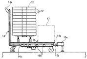
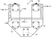
前記ラベル巻きロール搬送部(a)は、ラベル巻きロール10の搬送手段として本発明の重要な構成部材の一つである台車14を採用している。この台車14には、手押し部14aとその床面の周面に配された枠材14bとを有している。台車14の物品載置床面の面積は、前記ラベル巻きロール10の1個分の積載面積と、同ラベル巻きロール10の積載部の前方に隣り合って配される図2に仮想線で示す廃棄紙管12’の収納容器17の配置面積との和にほぼ等しい。前記ラベル巻きロール10の積載床面部には、長円形の巻きロール積載台16が固設されており、10〜20個のラベル巻きロール10が前記巻きロール積載台16に積み上げられて搭載されている。前記台車14の前端部に配される前記枠材14bには、図3A及び図3Bに示すように、台車停止領域15を構成するフレーム枠材15aの台車当接部に固設された当接部材15cと当接するストッパー14cが配されている。   The said label winding roll conveyance part (a) employ | adopts the trolley | bogie 14 which is one of the important structural members of this invention as a conveyance means of the label winding roll 10. FIG. The carriage 14 includes a hand pushing portion 14a and a frame member 14b disposed on the peripheral surface of the floor surface. The area of the article placement floor of the carriage 14 is the disposal area indicated by the phantom line in FIG. 2 arranged adjacent to the loading area of the label winding roll 10 and in front of the loading section of the label winding roll 10. It is approximately equal to the sum of the placement area of the storage container 17 of the paper tube 12 '. An oblong winding roll loading table 16 is fixed on the loading floor portion of the label winding roll 10, and 10 to 20 label winding rolls 10 are stacked and mounted on the winding roll loading table 16. Yes. As shown in FIGS. 3A and 3B, the frame member 14 b disposed at the front end of the carriage 14 is abutted to a carriage contact portion of a frame frame member 15 a constituting the carriage stop region 15. A stopper 14c that contacts the member 15c is disposed.

なお、本実施例では前記台車14の移動とラベル巻きロール10の台車14への積み上げ作業に人手が使われる場合を例に挙げているが、台車14の移動やラベル巻きロール10の台車14への積み上げ作業を、人手を使わずに機械化することも可能である。この場合、ラベル貼着機100の全工程が完全自動化されることになる。   In the present embodiment, the case where manual movement is used for the movement of the carriage 14 and the stacking work of the label winding roll 10 on the carriage 14 is taken as an example. However, the movement of the carriage 14 and the carriage 14 of the label winding roll 10 are performed. It is also possible to mechanize the stacking work without using manpower. In this case, all processes of the label sticking machine 100 are completely automated.

前記台車14上に設置された前記巻きロール積載台16の手押し部14a側とは反対側の隣接部位には、図2に示すとおり長尺の前記ラベル11の引出しを終えた後に残るラベル終端部を巻き付けた廃棄紙管12’の収納容器17が配置される。また、前記巻きロール積載台16に紙管12の中心軸線を共有して積み上げられた複数個のラベル巻きロール10の各周面に近接する部位には、図5Aに示すようにスプリング力を利用して、各ラベル巻きロール10の各周面の、ラベル引き出し始端の近傍を個別に押さえる弾圧押え部材18が多段に配されている。   As shown in FIG. 2, a label terminal portion remaining after the drawing of the long label 11 is completed at an adjacent portion on the opposite side to the hand pressing portion 14a side of the winding roll loading table 16 installed on the carriage 14. A storage container 17 of the waste paper tube 12 'around which is wound is disposed. Further, as shown in FIG. 5A, a spring force is used at a portion adjacent to each peripheral surface of the plurality of label winding rolls 10 stacked on the winding roll stack 16 sharing the central axis of the paper tube 12. And the elastic pressing member 18 which presses individually the vicinity of the label drawing start end of each peripheral surface of each label winding roll 10 is arranged in multiple stages.

台車14が上記構成を備えることにより、前述のラベル巻きロール搬送部(a)では、多数のラベル巻きロール10が集積される図示せぬ巻きロール集積領域に配された空の台車14上の巻きロール積載台16上に所要数のラベル巻きロール10を積載して、所定の台車停止領域15まで移動させて停止する。このとき、前記所要数のラベル巻きロール10は各紙管12の中心を一致させて台車14上の巻きロール積載台16に多段に積み重ねられて台車14に搭載されている。前記台車停止領域15は適当な柱や梁等を組み立てて構成され、台車14の入口と、台車14の左右枠部を挟持案内する複数のガイドローラー15bと、台車14の前面枠材14bに当接する当接部材15cとを有している。このように、各ラベル巻きロール10が垂直に多段に積み重ねられて台車14に搭載されるため、台車14上の巻きロール搭載面積は単一のラベル巻きロール10の横載置面の面積で足り、紙管12の収納容器17の設置面積を加えたとしても、その床面積を極力小さく抑えることが可能である。   When the cart 14 has the above-described configuration, in the label winding roll transport unit (a) described above, the winding on the empty cart 14 arranged in a winding roll accumulation region (not shown) in which a large number of label winding rolls 10 are accumulated. A required number of label winding rolls 10 are loaded on the roll loading table 16 and moved to a predetermined carriage stop area 15 to stop. At this time, the required number of label winding rolls 10 are stacked on the winding roll stack 16 on the carriage 14 and mounted on the carriage 14 with the centers of the paper tubes 12 aligned. The carriage stop region 15 is constructed by assembling appropriate columns, beams, and the like, and contacts the entrance of the carriage 14, a plurality of guide rollers 15b that sandwich and guide the left and right frame portions of the carriage 14, and the front frame member 14b of the carriage 14. And a contact member 15c in contact therewith. In this way, since each label winding roll 10 is vertically stacked in multiple stages and mounted on the carriage 14, the winding roll mounting area on the carriage 14 is sufficient for the area of the horizontal placement surface of the single label winding roll 10. Even if the installation area of the storage container 17 for the paper tube 12 is added, the floor area can be kept as small as possible.

更に所要数の紙管付きのラベル巻きロール10は前述のとおり同一垂直線上を多段に積み重ねられるため、ラベル巻きロール10の積載位置の近傍に配される前記処理テーブル111へのラベル巻きロール10の移載経路は、図2に示すように、停止台車の搭載位置に積み重ねられた複数の紙管付きラベル巻きロール10の各紙管12のうち最下段の紙管12の中心位置O1と、その直上の予め決められた高さ位置にある第1昇降位置P1との間の第1垂線経路Y1、前記第1昇降位置P1と上記処理テーブル111の回転中心O’を通る垂線上にあって前記第1の降下開始位置P1の高さと同じ高さ位置にある第2昇降位置P2とを結ぶ水平線経路X、前記回転中心O’及び前記水平線経路Xとが垂線軌道で結ばれる第2垂線経路Y2、及び前記水平線経路Xと前記収納容器17の紙管廃棄位置P3とが垂線軌道で結ばれる第3垂線経路Y3である。   Furthermore, since the required number of label winding rolls 10 with paper tubes are stacked in multiple stages on the same vertical line as described above, the label winding rolls 10 on the processing table 111 arranged in the vicinity of the loading position of the label winding rolls 10 are arranged. As shown in FIG. 2, the transfer path includes the center position O1 of the lowermost paper tube 12 among the paper tubes 12 of the plurality of label winding rolls with paper tubes 10 stacked at the mounting position of the stop carriage, and immediately above it. The first vertical path Y1 between the first elevating position P1 and the first elevating position P1 at a predetermined height position, and on the vertical line passing through the first elevating position P1 and the rotation center O ′ of the processing table 111, A horizontal line path X connecting the second lift position P2 at the same height as the height of the first descent start position P1, a second vertical path Y2 where the rotation center O ′ and the horizontal line path X are connected by a vertical track, And Wherein the horizontal line route X and the paper tube discarding position P3 of the container 17 is the third perpendicular path Y3, which are connected by a perpendicular trajectory.

これらの各経路X,Y1〜Y3は、いずれも同一の垂直平面内に配される直交直線経路となる。このことは、前記ラベル巻きロール10の把持解除部材112が4本の直線上に配された所定位置の間を格別なセンサーを配さずに所定のタイミングで停止と往復駆動を確実に繰り返して駆動ができる駆動手段をもって制御駆動させればよいことを意味する。   Each of these paths X, Y1 to Y3 is an orthogonal straight path arranged in the same vertical plane. This means that the grip releasing member 112 of the label winding roll 10 is repeatedly stopped and reciprocated at a predetermined timing without providing a special sensor between predetermined positions arranged on four straight lines. This means that it is sufficient to control and drive with a driving means capable of driving.

こうしたことから本実施例の上記ラベル巻きロール移載部(b)にあっては、前記駆動手段として格別のセンサーを用いずに位置決め制御を含む駆動制御が容易に且つ確実に実現できるACサーボモーターである第1及び第2サーボモーター113a,113bと第1及び第2ボールネジ114a,114bとの組み合わせを採用するとともに、様々なプログラムが書き込みできる記憶部を備えた制御盤115が設置されている。前記第1及び第2サーボモーター113a,113bの駆動部には前記第1及び第2ボールネジ114a,114bの各一端が固着一体化され、前記第1サーボモーター113a及び第1ボールネジ114aは、図6及び図7に示すように台車の一側面の近傍にあって、台車14の床面上の上記巻きロール積載台16のラベル巻きロール載置面の高さ位置に台車14の前後間に渡って水平に配され、一方の前記第2サーボモーター113b及び第2ボールネジ114bは、同図に示すように台車14の前記一側面の近傍で前記第1ボールネジ114aとの非干渉位置であって、台車14の全長の中央部位に天井部と前記巻きロール積載台16のラベル巻きロール載置面との間を全長にわたって垂直に配されている。   For this reason, in the label winding roll transfer section (b) of the present embodiment, an AC servo motor that can easily and reliably realize drive control including positioning control without using a special sensor as the drive means. A control panel 115 having a storage unit capable of writing various programs is installed while employing a combination of the first and second servo motors 113a and 113b and the first and second ball screws 114a and 114b. One ends of the first and second ball screws 114a and 114b are fixedly integrated with the driving portions of the first and second servo motors 113a and 113b. The first servo motor 113a and the first ball screw 114a are shown in FIG. 7 and in the vicinity of one side surface of the carriage, between the front and rear sides of the carriage 14 at the height position of the label winding roll mounting surface of the winding roll stack 16 on the floor surface of the carriage 14. The second servo motor 113b and the second ball screw 114b, which are horizontally disposed, are in a non-interfering position with the first ball screw 114a in the vicinity of the one side surface of the carriage 14 as shown in FIG. 14 is vertically arranged over the entire length between the ceiling portion and the label winding roll mounting surface of the winding roll stack 16 at the central portion of the total length 14.

なお、上記処理テーブル111は、図2に示すとおり台車14上に搭載されるラベル巻きロール10の積載高さよりも高い位置に配されることから、これらの配設位置を考慮すると、前記第2サーボモーター113b及び第2ボールネジ114bの配置位置は台車14の前後長さと前記処理テーブル111の径とを加えた長さの中央位置となる。   Since the processing table 111 is disposed at a position higher than the stacking height of the label winding roll 10 mounted on the carriage 14 as shown in FIG. The arrangement position of the servo motor 113b and the second ball screw 114b is the central position of the length obtained by adding the front-rear length of the carriage 14 and the diameter of the processing table 111.

ところで、前記第1及び第2サーボモーター113a,113bの各駆動部と前記制御盤115とは電気的に接続されており、同制御盤115の記憶部に書き込まれた所要のシーケンスプログラムに従った駆動信号が前記各サーボモーター113a,113bの各駆動部に順次出力される。また、上記ラベル巻きロール移載部(b)には、前記第1及び第2サーボモーター113a,113bの各駆動部が前記制御盤115からの前記駆動信号を受けると、上記第1垂線経路Y1、水平線経路X、第2垂線経路Y2及び第3垂線経路Y3に沿って所定の位置の間を垂直方向及び水平方向の同一平面上を自動的に移動する移動体116が配されている。   By the way, the drive units of the first and second servo motors 113a and 113b and the control panel 115 are electrically connected, and follow a required sequence program written in the storage unit of the control panel 115. A drive signal is sequentially output to each drive unit of each servomotor 113a, 113b. The label winding roll transfer unit (b) receives the drive signal from the control panel 115 when the drive units of the first and second servo motors 113a and 113b receive the first perpendicular path Y1. A moving body 116 that automatically moves between predetermined positions along the horizontal line X, the second perpendicular path Y2, and the third perpendicular path Y3 on the same plane in the vertical direction and the horizontal direction is disposed.

この移動体116は、図5A及び図5Bと図7に示すように、移動体本体116aと前記把持解除部材112の上半部を構成する把持解除作動部112aを支持する作動部支持部材116bとを有している。前記移動体本体116aは、図5A及び図5Bに示すとおり、全体が略U字状をなす板材からなり、その左右脚部の背面にそれぞれ上下一対の都合4個のガイド杆支持摺動部材19が配されている。このガイド杆支持摺動部材19には、前記第2ボールネジ114bの左右に配され同第2ボールネジ114bとほぼ同等の長さをもつ2本の摺動案内杆20が挿通されて前記移動体本体116aを第1垂線経路Y1に沿って摺動案内する。前記左右脚部の下端連結部の中央位置には、図5A、図5B及び図7に示すように上記第2ボールネジ114bのナット21が固設されており、同第2ボールネジ114bのネジ軸の両端は台車14の所定部位に固定されている支持板に取り付けられた通常の固定軸受22に回転可能に支持されている。   As shown in FIGS. 5A, 5B, and 7, the movable body 116 includes a movable body main body 116a and an operation portion support member 116b that supports a grip release operation portion 112a that constitutes the upper half of the grip release member 112. have. As shown in FIGS. 5A and 5B, the moving body main body 116a is made of a plate material having a substantially U shape as a whole, and a pair of upper and lower guide rod support sliding members 19 on the back of the left and right leg portions, respectively. Is arranged. Two sliding guide rods 20 disposed on the left and right sides of the second ball screw 114b and having substantially the same length as the second ball screw 114b are inserted into the guide rod supporting sliding member 19, and the movable body main body is inserted. 116a is slidably guided along the first perpendicular path Y1. As shown in FIGS. 5A, 5B, and 7, the nut 21 of the second ball screw 114b is fixed at the center position of the lower end connecting portion of the left and right leg portions, and the screw shaft of the second ball screw 114b is fixed. Both ends are rotatably supported by a normal fixed bearing 22 attached to a support plate fixed to a predetermined part of the carriage 14.

前記把持解除部材112の空圧作動部からなる上記把持解除作動部112aを支持する前記作動部支持部材116bは、図5A及び図5Bに示すとおり、前記移動体本体116aの上下中央の表面から台車14内の積載空間に向けて水平に延出する水平板材116b−1と、同水平板材116b−1の左右側外縁部から垂直に立ち上がる左右一対の垂直板材116b−2とを備え、上記ラベル巻きロール積載台16の巻きロール積載部中心を通る垂線と前記水平板材116b−1とが交差する交差部位で上記把持解除部材112の前記把持解除作動部112aを支持する。   As shown in FIG. 5A and FIG. 5B, the operation part support member 116b that supports the grip release operation part 112a, which is an air pressure operation part of the grip release member 112, is a cart from the surface of the movable body main body 116a at the center in the vertical direction. 14 is provided with a horizontal plate 116b-1 extending horizontally toward the loading space in 14 and a pair of left and right vertical plates 116b-2 rising vertically from the left and right outer edges of the horizontal plate 116b-1. The grip release actuating portion 112a of the grip release member 112 is supported at an intersecting portion where a perpendicular passing through the center of the roll roll stacking portion of the roll stack base 16 and the horizontal plate material 116b-1 intersect.

また前記水平板材116b−1の先端部の下面には、図5Aに示すように、次回に移載されるラベル巻きロール10の周面のラベル始端圧接位置と非圧接位置との間を僅かに移動してラベル11の引き出し始端部を押さえるラベル始端部押え器23がブラケットを介して固設され、前記移動体116の前記作動部支持部材116bに支持される前記把持解除作動部112aを挟んで前記ラベル始端部押え器23とは反対側の所定部位には、同じくブラケットを介して配され、ラベル11の引き出し完了時に残るラベル終端部を介して廃棄紙管12’を押さえるラベル終端部押え器24が固設されている。各端部押え器23,24は、それぞれの先端部に押え部材23a,24aを有しており、各押え部材23a,24aはエアシリンダー23b,24bの作動によりラベル巻きロール10及び廃棄紙管12’の各周面の押接位置と離間位置との間を進退する。   Further, on the lower surface of the front end portion of the horizontal plate member 116b-1, as shown in FIG. 5A, there is a slight gap between the label start end pressure contact position and the non-pressure contact position on the peripheral surface of the label winding roll 10 to be transferred next time. A label start-end presser 23 that moves and presses the pull-out start end of the label 11 is fixed via a bracket, and sandwiches the grip release operation portion 112a supported by the operation portion support member 116b of the moving body 116. A label end presser that is disposed on a predetermined portion opposite to the label start end presser 23 via a bracket and presses the waste paper tube 12 'through a label end remaining when the label 11 is completely pulled out. 24 is fixed. Each end presser 23, 24 has a presser member 23a, 24a at its tip, and each presser member 23a, 24a is operated by the air cylinders 23b, 24b to operate the label winding roll 10 and the waste paper tube 12. It moves forward and backward between the pressing position and the separating position of each circumferential surface.

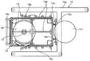
図4は本発明のラベル巻きロール移載装置における台車停止領域に隣接して配される処理テーブル111の回転機構の説明図である。同図に示すように、前記処理テーブル111は、上記フレーム枠材15aに各種のブラケット等を介して固定支持され、前記処理テーブル111から下方に延びる円筒状支柱27に固設されたベルトプーリー28に巻き回されたベルト26により駆動回転する。   FIG. 4 is an explanatory diagram of the rotation mechanism of the processing table 111 arranged adjacent to the carriage stop region in the label winding roll transfer device of the present invention. As shown in the figure, the processing table 111 is fixedly supported on the frame frame member 15a via various brackets and the like, and a belt pulley 28 fixed to a cylindrical column 27 extending downward from the processing table 111. The belt is wound around the belt 26 and rotated.

そのテーブル支持構造とテーブル回転機構とをより具体的に述べると、処理テーブル111の中心部にはラベル巻きロール10の紙管12の外径よりも僅かに小さい内径の貫通孔111aが形成されており、同貫通孔111aの下面周縁部に沿って円筒形の大径部と小径部とを有する円筒状支柱27の上端が前記貫通孔111aの中心を合わせて処理テーブル111に固設されている。前記円筒状支柱27の内部空間にはスプライン軸29が配されており、その上端にボス29bを介して一体化した摺動ブロック30が上下に移動可能に支持されている。前記円筒状支柱27の下端にはベルトプーリー28が固設されている。また、前記スプライン軸29の下端部は前記円筒状支柱27の中間部に固定したスプラインボス29aに上下に移動可能でかつ回転可能に挿通案内されている。一方、前記スプライン軸29の下端部にはブロック支持管31を上下動可能に案内保持する支持杆保持部材29cが垂直下方に向けて延設されている。   More specifically, the table support structure and the table rotation mechanism are formed with a through hole 111a having an inner diameter slightly smaller than the outer diameter of the paper tube 12 of the label winding roll 10 at the center of the processing table 111. The upper end of a cylindrical column 27 having a cylindrical large-diameter portion and a small-diameter portion is fixed to the processing table 111 along the periphery of the lower surface of the through-hole 111a with the center of the through-hole 111a aligned. . A spline shaft 29 is disposed in the internal space of the cylindrical support column 27, and a slide block 30 integrated with the upper end of the cylindrical support column 27 via a boss 29b is supported so as to be movable up and down. A belt pulley 28 is fixed to the lower end of the cylindrical support 27. Further, the lower end portion of the spline shaft 29 is guided through a spline boss 29a fixed to an intermediate portion of the cylindrical column 27 so as to be movable up and down and rotatable. On the other hand, at the lower end of the spline shaft 29, a support rod holding member 29c for guiding and holding the block support tube 31 so as to be movable up and down is extended vertically downward.

更に、前記スプライン軸29の内部空間には、上端部が前記摺動ブロック30の中心孔30aに遊挿されるブロック支持管31が垂直に配されている。このブロック支持管31の上端は、給排気により外径が膨張/収縮して、前記ラベル巻きロール10の中心に配された上記紙管12の内周面に圧接/離間する、図4に仮想線で示す、本発明のロール支持部材の一部である空圧接離部材32の給排気口と接続一体化されている。前記ブロック支持管31の下端には図示せぬ機外の給排気源と接続された給排気用シリンダー31aが取り付けられている。   Further, in the internal space of the spline shaft 29, a block support tube 31 whose upper end is loosely inserted into the center hole 30a of the sliding block 30 is disposed vertically. The upper end of the block support pipe 31 expands / contracts due to air supply / exhaust, and is pressed / separated from the inner peripheral surface of the paper tube 12 disposed at the center of the label winding roll 10, as shown in FIG. It is connected and integrated with the air supply / exhaust port of the pneumatic contact / separation member 32, which is a part of the roll support member of the present invention, indicated by a line. A supply / exhaust cylinder 31a connected to a supply / exhaust source outside the machine (not shown) is attached to the lower end of the block support pipe 31.

こうした回転/上下動機構を備えた処理テーブル111の上記円筒状支柱27は、図4に示すように、機枠の一部フレーム枠材15aに直接固設されたフランジ付きの円筒状支持部材33に玉軸受33aを介して回転自在に支持されている。前記円筒状支持部材33の前記フランジから支持ブラケット34bが下方に突出しており、同支持ブラケット34bの下端部に空圧シリンダー34が固設されている。該空圧シリンダー34のピストン下端部には水平ブラケット34cが上下動可能に支持されている。前記処理テーブル111に固設された前記円筒状支柱27は前記フレーム枠材15aに固設された前記円筒状支持部材33と玉軸受33aを介して回転可能に支持固定されている。   As shown in FIG. 4, the cylindrical support 27 of the processing table 111 having such a rotation / vertical movement mechanism is provided with a flanged cylindrical support member 33 directly fixed to a part of the frame frame material 15a of the machine frame. Are supported rotatably via ball bearings 33a. A support bracket 34b protrudes downward from the flange of the cylindrical support member 33, and a pneumatic cylinder 34 is fixed to the lower end portion of the support bracket 34b. A horizontal bracket 34c is supported at the lower end of the piston of the pneumatic cylinder 34 so as to be movable up and down. The cylindrical column 27 fixed to the processing table 111 is rotatably supported and fixed via the cylindrical support member 33 and ball bearing 33a fixed to the frame frame member 15a.

上記ベルトプーリー28がベルト26により駆動回転すると、処理テーブル111が回転し、処理テーブル111が回転すると前記スプライン軸29が前記摺動ブロック30とともに回転する。この回転時に、図4に示す空圧シリンダー34が作動してピストンを所定の距離を上下動させると、前記空圧接離部材32は前記摺動ブロック30とともに前記円筒状支柱27の円筒内外の間を所定の距離を上下に摺動するが、前記ブロック支持管31は前記ベルトプーリー28による積極的な回転機構を備えていないため、同ブロック支持管31に接続される前記空圧接離部材32もまた回転しない。   When the belt pulley 28 is driven and rotated by the belt 26, the processing table 111 rotates, and when the processing table 111 rotates, the spline shaft 29 rotates together with the sliding block 30. During this rotation, when the pneumatic cylinder 34 shown in FIG. 4 is operated to move the piston up and down a predetermined distance, the pneumatic contact / separation member 32 moves between the cylindrical block 27 and the cylindrical support 27 together with the sliding block 30. However, since the block support pipe 31 does not have a positive rotation mechanism by the belt pulley 28, the pneumatic contact / separation member 32 connected to the block support pipe 31 is also provided. Also does not rotate.

上記ラベル貼着機100の全ての点検が終わった稼働開始時には、ラベル巻きロール移載装置110の台車停止領域15の所定停止位置には複数のラベル巻きロール10を搭載した台車14が停止している。ここで前記把持解除部材112の前記把持解除作動部112aを作動して前記ラベル巻きロール10の把持と解除を行わせる。また、上記第1サーボモーター113a及び第2サーボモーター113bの各駆動部が前記制御盤115から駆動信号を受けると、各サーボモーター113a,113bの各駆動部が前記駆動信号に対応する駆動を開始させる。   At the start of operation after all the inspections of the label sticking machine 100 are completed, the carriage 14 loaded with the plurality of label winding rolls 10 stops at a predetermined stop position in the carriage stop area 15 of the label winding roll transfer device 110. Yes. Here, the grip release operation part 112a of the grip release member 112 is operated to cause the label winding roll 10 to be gripped and released. Further, when the drive units of the first servo motor 113a and the second servo motor 113b receive a drive signal from the control panel 115, the drive units of the servo motors 113a and 113b start driving corresponding to the drive signal. Let

これらの駆動は、前記制御盤115の記憶部に書き込まれたシーケンスプログラムに従って逐次なされるが、特にその駆動手段としてサーボモーターが使われているため、内蔵するエンコーダのフィードバック制御により、その駆動タイミングの制御や速度制御及び位置制御が自動的に正確に且つ高速になされる。例えば、本実施例によれば第1サーボモーター113a及び第1ボールネジ114aが一体化して水平に、また第2サーボモーター113b及び第2ボールネジ114bが一体化して垂直に、各ボールネジ114a,114bが上記移動体116を介して所定の間隔をおいて、互いが干渉しないように交差して配されていることから、前記移動体116に支持された上記把持解除部材112を所定の位置の間を垂直方向及び水平方向に正確に且つ高速に移動させることが可能である。   These drives are sequentially performed in accordance with a sequence program written in the storage unit of the control panel 115. In particular, since a servo motor is used as the drive means, the drive timing is controlled by feedback control of the built-in encoder. Control, speed control and position control are automatically performed accurately and at high speed. For example, according to the present embodiment, the first servo motor 113a and the first ball screw 114a are integrated and horizontally, the second servo motor 113b and the second ball screw 114b are integrated and vertically, and the ball screws 114a and 114b are connected to each other. Since the movable body 116 is arranged so as to intersect with each other at a predetermined interval through the movable body 116, the grip release member 112 supported by the movable body 116 is vertically disposed between the predetermined positions. It is possible to move in the direction and the horizontal direction accurately and at high speed.

また第1及び第2サーボモーター113a,113bを所定のタイミングをもって上記把持解除部材112の前記把持解除作動部112aを作動させてラベル巻きロール10又は廃棄紙管12’を所定の把持解除位置にて自動的に把持又は解除する。本実施例における紙管12付きラベル巻きロール10の上記把持解除部材112として、例えばエアの給排気に応じて径方向に拡縮し、給気による拡径時にその表面が紙管12の内面を広い面積をもって強く圧着してラベル巻きロール10や廃棄紙管12’を吊り下げて把持することができ、排気により前記表面を縮径させて、前記ラベル巻きロール10の把持を解除する吊り具が好適に用いられるが、他の方式の市販されている把持解除部材を用いることもできる。   Further, the first and second servo motors 113a and 113b are operated at a predetermined timing to operate the grip release operation part 112a of the grip release member 112 so that the label winding roll 10 or the waste paper tube 12 ′ is moved to a predetermined grip release position. Grasping or releasing automatically. As the grip release member 112 of the label winding roll 10 with the paper tube 12 in the present embodiment, for example, the surface is expanded or contracted in the radial direction according to air supply / exhaust, and the surface widens the inner surface of the paper tube 12 when the diameter is increased by supply air. A lifting tool that can suspend and grip the label winding roll 10 and the waste paper tube 12 ′ by pressing firmly with an area, and reduces the diameter of the surface by exhaust to release the gripping of the label winding roll 10 is preferable. However, other types of commercially available grip release members can also be used.

ここで、本実施例に係るラベル巻きロールの移載装置は、台車14上に積載された複数のラベル巻きロール10を順次把持して処理テーブル111へと移載する移載部だけに止まらず、処理テーブル111に移載されたラベル巻きロール10から引き出される長尺のラベルを所定の長さごとに切断し、切断された各ラベル片を次工程である捺印ドラム部120に送り込むまでの工程を含むとともに、ラベル引出し完了時に処理テーブル111上に残される紙管12を自動的に収納容器に廃棄する工程をも含むものである。そのため本実施例にあっては、上述のラベル巻きロール移載部(b)には、次の設備を備えている。   Here, the label winding roll transfer device according to the present embodiment is not limited to the transfer unit that sequentially holds the plurality of label winding rolls 10 loaded on the carriage 14 and transfers them to the processing table 111. The process of cutting a long label drawn from the label winding roll 10 transferred to the processing table 111 for each predetermined length and feeding each cut label piece to the printing drum unit 120 as the next process. And a step of automatically discarding the paper tube 12 left on the processing table 111 when the label drawing is completed into the storage container. Therefore, in the present Example, the above-mentioned label winding roll transfer part (b) is equipped with the following equipment.

前記処理テーブル111上に移載された前記紙管12付きのラベル巻きロール10のラベル引き出し始端の近接部位に、ラベル始端部吸着移送部材40が配設されている。このラベル始端部吸着移送部材40は、ラベル巻きロール10の引出し移送経路に配されたダンサーローラーユニット42を備えた張力調整部と、ラベル巻きロール10のラベル引き出し始端を円滑に引き出す引き出しローラー対40aと、次工程の前記捺印ドラム部120のラベル片導入部位に配されるラベル切断部60との間の引出し移送切断経路へとラベル11を円滑に送り出す部材であって、本実施例では所定の吸着面を有し、前記ラベル巻きロール10のラベル引き出し始端部とその待機位置との間を移動可能で、且つ前記ラベル引き出し始端部への接近時に吸気して前記吸着面をもって前記ラベル引き出し始端部を吸着する。   A label start end suction transfer member 40 is disposed in the vicinity of the label draw start end of the label winding roll 10 with the paper tube 12 transferred onto the processing table 111. The label start end suction transfer member 40 includes a tension adjusting unit including a dancer roller unit 42 disposed in a drawing transfer path of the label winding roll 10 and a pullout roller pair 40a that smoothly pulls out the label pulling start end of the label winding roll 10. And a member that smoothly feeds the label 11 to a drawing transfer cutting path between the label cutting portion 60 arranged in the label piece introduction portion of the marking drum portion 120 in the next process, It has a suction surface, is movable between the label drawing start end portion of the label winding roll 10 and its standby position, and sucks air when approaching the label drawing start end portion, and has the suction surface and the label drawing start end portion. To adsorb.

前記ラベル始端部吸着移送部材40は、前記張力調整部の前記固定ガイドローラー40a’と前記引き出し移送切断経路を横切って前記固定ガイドローラー40a’に接離可能に動作する回転駆動ローラー40a”とからなる引き出しローラー対40aを備えており、制御盤115からの信号を受けて前記引き出し始端部の一部を吸着把持後、その始端部を前記引き出しローラー対40aの上流側に隣接して配される固定ローラー41aを介して引き出しローラー対40aに移送導入したのち、同始端部の吸着を解除して処理テーブル111の近傍の元の待機位置まで戻る。このときのラベル始端部吸着後の現実のラベル引き出し始端は、前記回転駆動ローラー40a”の配設位置まで延びている。   The label start end suction transfer member 40 includes the fixed guide roller 40a ′ of the tension adjusting unit and a rotation driving roller 40a ″ that operates to come in contact with and separate from the fixed guide roller 40a ′ across the drawer transfer cutting path. The drawing roller pair 40a is provided, and after receiving a signal from the control panel 115 and sucking and gripping a part of the drawing start end portion, the start end portion is arranged adjacent to the upstream side of the drawing roller pair 40a. After the transfer and introduction to the drawing roller pair 40a via the fixed roller 41a, the suction at the start end is released and the original standby position near the processing table 111 is returned to the actual label after the label start end is sucked at this time. The leading end of the drawer extends to the position where the rotation driving roller 40a ″ is disposed.

前記張力調整部のダンサーローラーユニット42には複数の固定ローラー41aと複数のダンサーローラー41bとがラベル移送経路に沿って整列して配されており、そのラベル移送経路内に出入りする平板からなる図示せぬラベル走行ガイド板が同移送路に起立して配されている。このラベル走行ガイド板の作動部、制御盤115からの信号を受けて、ラベル11の引き出し始端の通過時には前記ラベル走行ガイド板がラベル移送経路まで下降し、ラベルの通常走行時には固定ローラー41aと複数のダンサーローラー40bとを越える高さ位置までラベル移送経路から退避したのち、前記複数のダンサーローラー41bが前記固定ローラー41aの間を図示せぬ弾力付与手段の弾力に抗して一斉に下方へと移動する。   A plurality of fixed rollers 41a and a plurality of dancer rollers 41b are arranged along the label transfer path in the dancer roller unit 42 of the tension adjusting unit, and are composed of flat plates that enter and exit the label transfer path. A label travel guide plate (not shown) is erected on the transfer path. Upon receiving a signal from the label travel guide plate operating unit and the control panel 115, the label travel guide plate descends to the label transport path when the label 11 passes through the leading end of the label 11, and a plurality of the fixed roller 41a and the plurality of fixed rollers 41a during normal travel of the label. The plurality of dancer rollers 41b move downward between the fixed rollers 41a all at once against the elasticity of the elasticity applying means (not shown) between the plurality of dancer rollers 41a. Moving.

前記処理テーブル111の中心部に移載された前記ラベル巻きロール10の前記ラベル始端引き出し経路の終端には前記ラベル11を所定の長さに切断するラベル切断部60を有している。このラベル切断部60と前記張力調整部との間の始端引き出し経路の途中には、ラベル11を積極的に送り出す一対の圧接ローラー51,51を有する送りローラー部50が配されている。前記ラベル切断部60は、一般的な駆動回転ローラー61と、同駆動回転ローラー61と同期して逆方向に回転し、その周面の一部に回転軸に平行な直線的に切断刃を有する切断ローラー62とを備え、更にこのラベル切断部60と前記送りローラー部50との間のラベル始端引き出し経路上には長尺のラベル11上に所定の間隔をおいて印刷されている切断マーク位置を検出するマーク位置検出器63を備えている。   A label cutting unit 60 that cuts the label 11 to a predetermined length is provided at the end of the label starting end drawing path of the label winding roll 10 transferred to the center of the processing table 111. A feeding roller unit 50 having a pair of press rollers 51 and 51 that actively feeds the label 11 is disposed in the middle of the leading end drawing path between the label cutting unit 60 and the tension adjusting unit. The label cutting unit 60 rotates in the reverse direction in synchronization with a general drive rotation roller 61 and the drive rotation roller 61, and has a linear cutting blade parallel to the rotation axis at a part of its peripheral surface. A cutting mark position which is provided with a cutting roller 62 and is printed on the long label 11 at a predetermined interval on the label starting end drawing path between the label cutting unit 60 and the feeding roller unit 50. A mark position detector 63 is provided.

次に、上記巻きロール移載部における前記ラベル巻きロール10及び廃棄紙管12’の把持、移送、解除の各操作及び処理テーブル111上への自動移載手順を図面を参照して具体的に説明する。
上記実施例にあっては、把持解除部材である上記吊り具112に、使用空気圧が0.45〜0.7Mpaの範囲にあり、最大吊荷重が40kgの「(株)ハイメックス社製ハイロック(商品名)」が使われている。上記ラベル巻きロール自動移載装置110の稼働時、台車14は上記ラベル巻きロール自動移載装置110の前記台車停止領域15に停止している。台車14には複数の巻きロール積載台16上に積み重ねてられている。その積載されたラベル巻きロール10の紙管中心を通る上記第1垂線経路Y1上の上記第1降下開始位置P1には、図2に示すとおり、移動体116が待機している。
Next, each operation of gripping, transferring, and releasing the label winding roll 10 and the waste paper tube 12 ′ in the winding roll transfer section and the automatic transfer procedure on the processing table 111 will be specifically described with reference to the drawings. explain.
In the above embodiment, the lifting tool 112 serving as a grip release member has a working air pressure in the range of 0.45 to 0.7 MPa and a maximum suspension load of 40 kg. (Product name) "is used. When the label winding roll automatic transfer device 110 is in operation, the carriage 14 is stopped in the cart stop area 15 of the label winding roll automatic transfer device 110. The carriage 14 is stacked on a plurality of winding roll loading platforms 16. As shown in FIG. 2, the moving body 116 stands by at the first descent start position P1 on the first perpendicular path Y1 passing through the paper tube center of the loaded label winding roll 10.

ここで、上記第2サーボモータ113bが上記制御盤115からの駆動信号を受けて駆動を開始し、第1降下開始位置P1に配された第2サーボモータ113bの垂直下方に伸びる第2ボールネジ114bを所望の速度で下降方向に回転させる。この回転により、第2ボールネジ114bの上端部に取り付けられた上記移動体116は前記吊り具112とともに下降を開始して、前記吊り具112が直下に配された最上段のラベル巻きロール10を取りにいく。   Here, the second servo motor 113b receives the drive signal from the control panel 115 and starts driving, and the second ball screw 114b extending vertically below the second servo motor 113b disposed at the first descent start position P1. Is rotated in the downward direction at a desired speed. By this rotation, the moving body 116 attached to the upper end portion of the second ball screw 114b starts to move down together with the hanger 112, and takes the uppermost label winding roll 10 on which the hanger 112 is arranged directly below. go to.

前記吊り具112の下端部に配された把持解除部112bが前記ラベル巻きロール10の紙管12の中心部に挿入されると、図5Aに示すとおり、前記吊り具112の把持解除作動部112aを介して把持解除部112bに空圧が供給され、把持解除部112bが拡径し紙管12の内面を押圧して前記ラベル巻きロール10を把持する。このとき同時に上記ラベル始端部押え器23の押え部材23aが前記ラベル巻きロール10の周面のラベル始端部に当接して、ラベル始端部のほぐれを防止する。こうして、前記ラベル巻きロール10の把持がなされると、次いで第2サーボモーター113bが駆動を開始して第2ボールネジ114bを逆転させて、前記ラベル巻きロール10を移動体116を介して直上の上記第1降下開始位置P1へと移動させたのち駆動を停止する。   When the grip release portion 112b disposed at the lower end portion of the hanger 112 is inserted into the central portion of the paper tube 12 of the label winding roll 10, the grip release operation portion 112a of the hanger 112 is shown in FIG. 5A. Then, pneumatic pressure is supplied to the grip release unit 112b, and the grip release unit 112b expands in diameter and presses the inner surface of the paper tube 12 to grip the label winding roll 10. At the same time, the pressing member 23a of the label start end presser 23 abuts against the label start end of the peripheral surface of the label winding roll 10 to prevent the label start end from coming loose. Thus, when the label winding roll 10 is gripped, the second servo motor 113b then starts to drive, reverses the second ball screw 114b, and causes the label winding roll 10 to move directly above the moving body 116. The drive is stopped after moving to the first descent start position P1.

この第2サーボモーター113bの駆動が停止すると、続いて前記第1サーボモーター113aが駆動を開始し、第1ボールネジ114aを所定の回転速度で駆動回転させて、前記移動体116をラベル巻きロール10を把持したまま、図2に示す水平線経路Xに沿って図面左側の第2昇降位置P2へと移送し、前記第1サーボモーター113aの駆動を停止させる。この停止を待って、前記第2サーボモーター113bが駆動を開始し、第2垂線経路Y2に配された第2ボールネジ114bを下降方向に回転して前記移動体116を下降させたのち前記把持解除部112bによる把持を解除して、前記ラベル巻きロール10を台車停止位置に隣接して設置された処理テーブル111上の中心部へと移載する。   When the driving of the second servo motor 113b is stopped, the first servo motor 113a starts to drive, and the first ball screw 114a is driven to rotate at a predetermined rotational speed, so that the moving body 116 is moved to the label winding roll 10 2 is moved to the second lift position P2 on the left side of the drawing along the horizontal line path X shown in FIG. 2, and the driving of the first servo motor 113a is stopped. Waiting for this stop, the second servo motor 113b starts to drive, rotates the second ball screw 114b arranged in the second perpendicular path Y2 in the downward direction, lowers the movable body 116, and then releases the grip. The gripping by the part 112b is released, and the label winding roll 10 is transferred to the central part on the processing table 111 installed adjacent to the carriage stop position.

この移載を終えると、前記第2サーボモーター113bの駆動が停止するとともに、前記吊り具112の把持解除部112bの空圧が前記把持解除作動部112aを介して抜かれ、吊り具112による前記ラベル巻きロール10の把持を解除する。このラベル巻きロール10の把持が解除されると、前記第2サーボモーター113bの逆転駆動が開始されると同時に、上記空圧シリンダー34に向けて機外に配される図示せぬ空圧供給源から空気が送られ、ピストン34aが下方に伸長し、該ピストン34aの下端に水平に固設されたブラケット34cを介して上記空圧接離部材32、摺動ブロック30、スプライン軸29及び支持杆保持部材29cを、回転させることなくスプラインボス29aに案内されて、前記空圧接離部材32の頂点と処理テーブル111の上面とが一致する位置まで下降してラベル巻きロール10の処理テーブルへの移載作業が終了する。   When the transfer is completed, the driving of the second servo motor 113b is stopped, and the pneumatic pressure of the grip releasing portion 112b of the lifting tool 112 is released via the grip releasing operation portion 112a, and the label by the lifting tool 112 is removed. The gripping of the winding roll 10 is released. When the gripping of the label winding roll 10 is released, the reverse drive of the second servo motor 113b is started, and at the same time, an unillustrated pneumatic supply source arranged outside the machine toward the pneumatic cylinder 34 The piston 34a extends downward, and the pneumatic contact / separation member 32, the sliding block 30, the spline shaft 29, and the support rod are held via a bracket 34c fixed horizontally to the lower end of the piston 34a. The member 29c is guided to the spline boss 29a without rotating, and is lowered to a position where the apex of the pneumatic contact / separation member 32 and the upper surface of the processing table 111 coincide with each other, and the label winding roll 10 is transferred to the processing table. The work is finished.

この移載が終了すると、続いて処理テーブル111上に載置されたラベル巻きロール10の引き出し始端部の近傍に配された上記ラベル始端部吸着移送部材40が吸着を開始するともに、前記ラベル巻きロール10の周面のラベル引き出し始端部まで移動して同始端部を吸着する。この吸着後、前記ラベル始端部吸着移送部材40は上記サーボモーターユニット42の手前に配された固定ガイドローラー40a’の配設位置まで移動し、そこで前記固定ガイドローラー40a’との当接位置まで移動して一旦停止したのち始端部の吸着を解除する。この吸着が解除されると、前記ラベル始端部吸着移送部材40は同じ経路に沿って処理テーブル111の近傍の待機位置まで自動的に戻る。ところで、前記ラベル始端部吸着移送部材40により吸着されているラベル引き出し始端部の先端は、前記固定ガイドローラー40a’に隣接する上記引き出しローラー対40aまで延びており、ラベル11は前記引き出しローラー対40aが駆動されているため、その引き出しは維持され続ける。   When the transfer is completed, the label start end suction transfer member 40 disposed in the vicinity of the drawing start end of the label winding roll 10 placed on the processing table 111 starts suction, and the label winding It moves to the label drawing start end of the peripheral surface of the roll 10 and sucks the start end. After this suction, the label start end suction transfer member 40 moves to the position where the fixed guide roller 40a ′ disposed in front of the servo motor unit 42 is located, where it reaches the contact position with the fixed guide roller 40a ′. After moving and temporarily stopping, the suction at the starting end is released. When this suction is released, the label start end suction transfer member 40 automatically returns to the standby position near the processing table 111 along the same path. By the way, the leading end of the label drawing start end adsorbed by the label start end adsorbing / transferring member 40 extends to the drawing roller pair 40a adjacent to the fixed guide roller 40a ′, and the label 11 is the drawing roller pair 40a. Since it is driven, its drawer continues to be maintained.

前記引き出しローラー対40aにより引き出されるラベル始端部は、上記張力調整部の引き出し経路に配された図示せぬ上記ラベル走行ガイド板にガイドされて他の周辺部材と干渉することなく、上記送りローラー部50を経て上記ラベル切断部60まで円滑に送られる。このラベル移送の間、上記ダンサーローラーユニット42のダンサーローラー41bが隣り合う上記固定ローラー41aの間を弾力に抗して下方に移動して、ラベル11を固定ローラー41aとダンサーローラー41bとの間でジグザグ状に案内して張力を調整する。また、前記ラベル切断部60に配された上記マーク位置検出器63により切断位置マークが検出され、その検出信号が上記制御盤115に送られて駆動回転ローラー61及び切断ローラー62を駆動して、ラベル11を所定長ごとに切断し、切断されたラベル片11’を所定の間隔をおいて次工程の捺印ドラム部(c)へと順次送り込む。   The feed roller portion is guided by the label travel guide plate (not shown) disposed in the pull-out path of the tension adjusting unit without interfering with other peripheral members as the label start end portion pulled out by the pull-out roller pair 40a. 50 and smoothly fed to the label cutting unit 60. During this label transfer, the dancer roller 41b of the dancer roller unit 42 moves downward between the adjacent fixed rollers 41a against elasticity, and the label 11 is moved between the fixed roller 41a and the dancer roller 41b. Guide the zigzag to adjust the tension. Further, the mark position detector 63 disposed in the label cutting unit 60 detects a cutting position mark, and the detection signal is sent to the control panel 115 to drive the driving rotary roller 61 and the cutting roller 62, The label 11 is cut into predetermined lengths, and the cut label pieces 11 ′ are sequentially fed to the printing drum portion (c) in the next process at a predetermined interval.

一方、処理テーブル111上のラベル巻きロール10の周面に向けてラベル終端センサー44が配されており、前記ラベル巻きロール10にマーキングされた終端部マークを検出して、その検出信号を制御盤115に送ると、制御盤115から上記ベルト26の図示せぬ駆動源に信号が送られ、処理テーブル111の回転を逆転させてラベル11の終端部を紙管12に巻き戻す。この巻き戻しが終わると、上記移動体11に搭載された上記移動体116に搭載された上記吊り具112が上記第2昇降位置P2から第2垂直経路Y2下降して、その把持解除部112bが処理テーブル111上のラベル終端部が巻き付いた廃棄紙管12’の中心へと挿入される。この挿入時、上記空圧シリンダー34が作動して、それまでテーブル上面から上方に突出していた空圧接離部材32(図4)をテーブル下方へと引っ込ませ、前記吊り具112の把持解除部112bをラベル11の引き出し完了時に残るラベル終端部が巻き付いた廃棄紙管12’の中心に挿入する。   On the other hand, a label end sensor 44 is arranged toward the peripheral surface of the label winding roll 10 on the processing table 111. The end mark marked on the label winding roll 10 is detected, and the detection signal is sent to the control panel. When the signal is sent to 115, a signal is sent from the control panel 115 to a drive source (not shown) of the belt 26, the rotation of the processing table 111 is reversed, and the end portion of the label 11 is rewound onto the paper tube 12. When this rewinding is finished, the suspension 112 mounted on the moving body 116 mounted on the moving body 11 descends from the second elevating position P2 to the second vertical path Y2, and the grip releasing portion 112b is moved. It is inserted into the center of the waste paper tube 12 'around which the label end portion on the processing table 111 is wound. At the time of this insertion, the pneumatic cylinder 34 is operated, and the pneumatic contact / separation member 32 (FIG. 4) that has been projected upward from the upper surface of the table until then is retracted to the lower side of the table. Is inserted into the center of the waste paper tube 12 'around which the end of the label remaining when the label 11 has been pulled out.

この挿入が終わると、図5Aに示すラベル終端部押え器24のエアシリンダー24bが作動し、その押え部材24aによって前記廃棄紙管12’の周面を押さえ、ラベル終端部がほぐれないようにして、前記廃棄紙管12’を把持する。次いで、上記第2サーボモーター113bが駆動されて、移動体116に固定把持された前記廃棄紙管12’を前記第2垂線経路Y2に沿って上昇させて前記第2昇降位置P2へと移動させる。この移動が終了すると、続いて上記第1サーボモーター113aが駆動され、前記移動体116を前記廃棄紙管12’を把持したまま上記水平線経路Xに沿って台車上に置かれた上記廃棄紙管12’の上記収納容器17の直上の紙管廃棄位置P3まで移動し、そこで上記吊り具112の把持解除作動部112aを介して把持解除部112bが自動的に作動し、前記廃棄紙管12’の把持を解除して自然落下させて前記収納容器17に収納する。前記把持解除作動部112aの作動が終わると移動体116は単独で同じ水平線経路Xを上記第1昇降位置P1へと移動する。   When this insertion is finished, the air cylinder 24b of the label end retainer 24 shown in FIG. 5A is operated, and the press member 24a presses the peripheral surface of the waste paper tube 12 'so that the label end does not come loose. The waste paper tube 12 'is gripped. Next, the second servo motor 113b is driven, and the waste paper tube 12 ′ fixedly gripped by the moving body 116 is moved up along the second perpendicular path Y2 and moved to the second lift position P2. . When this movement is completed, the first servo motor 113a is subsequently driven, and the waste paper pipe placed on the carriage along the horizontal line path X while holding the waste paper pipe 12 'while holding the waste paper pipe 12'. 12 'is moved to the paper tube discarding position P3 immediately above the storage container 17, and the grip releasing portion 112b is automatically operated via the grip releasing operation portion 112a of the lifting tool 112, and the waste paper tube 12' Is released and naturally dropped and stored in the storage container 17. When the operation of the grip release operation unit 112a is finished, the moving body 116 independently moves on the same horizontal line path X to the first elevating position P1.

以上述べたとおり、ラベル巻きロール10の所定経路に沿った水平移動及び垂直移動と、所定の位置でのラベル巻きロール10の把持/解除操作及びその操作タイミングが全て上記制御盤115からの指令と同制御盤115の記憶部に書き込まれたシーケンスプログラムに従って自動的になされる。そして、これらの移動、操作及びタイミングが繰り返されて、ラベル片11’が次工程以降のラベル捺印ドラム部120及びラベル貼着ドラム部130へと順次送り込まれ、捺印、糊付け後に連続して小瓶13などの周面に自動的に貼着される。   As described above, the horizontal movement and vertical movement of the label winding roll 10 along the predetermined path, the gripping / releasing operation of the label winding roll 10 at the predetermined position, and the operation timing thereof are all commands from the control panel 115. This is automatically done according to the sequence program written in the storage unit of the control panel 115. Then, the movement, operation and timing are repeated, and the label pieces 11 ′ are sequentially fed to the label printing drum section 120 and the label sticking drum section 130 in the subsequent processes, and after the printing and pasting, the small bottle 13 It is automatically attached to the surrounding surface.

ここで本実施例によれば、同じ構成を備えた2基(A),(B)のラベル巻きロール自動移載装置110が前記捺印ドラム部120に接続されている。
そのため、上記ラベル貼着機100には上記ラベル巻きロール移載部(b)に続いて、以下に述べるような捺印ドラム部120とラベル貼着ドラム部130とが備えられている。前記捺印ドラム部120及びラベル貼着ドラム部130の大半は、一般に広く知られており、本実施例における後述の貼着仕上げベルト142によるラベル付き瓶の仕上げ工程を除くと、本発明に特有の格別の特徴的な構成は備えていない。そのため以下の説明では捺印ドラム部120及びラベル貼着ドラム部130についての詳しい説明は省略する。
Here, according to the present embodiment, two (A) and (B) label winding roll automatic transfer devices 110 having the same configuration are connected to the stamping drum unit 120.
Therefore, the label sticking machine 100 is provided with a printing drum part 120 and a label sticking drum part 130 as described below, following the label winding roll transfer part (b). Most of the stamping drum portion 120 and the label sticking drum portion 130 are generally widely known. Except for the labeling bottle finishing process by the sticking finish belt 142 to be described later in this embodiment, it is unique to the present invention. There is no special characteristic configuration. Therefore, in the following description, the detailed description about the marking drum part 120 and the label sticking drum part 130 is abbreviate | omitted.

前記捺印ドラム部120は、図1に示すように、上記ラベル巻きロール移載装置110の最終処理部であるラベル切断部60に隣接して配されており、その主な構成部材は捺印ドラム121であって、上記ラベル貼着機100の稼働中は定常的に一方向に所定の速度で駆動回転しており、前記ラベル切断部60にて所定の長さに切断されたラベル片11’を所定の間隔をおいて捺印ドラム121の周面に負圧を使って順次吸着して次工程のラベル貼着ドラム部130に順次移行させる。前記捺印ドラム121の周面の近傍には、その回転方向の下流側に向けて、ラベル位置修正器122、捺印機123、捺印検査器124の順に順次間隔をおいて配されている。前記捺印ドラム121の周面の回転速度はラベル貼着ドラム131の周面の回転速度より小さく、その速度差によって前記捺印ドラム121の周面に吸着される前記ラベル切断部60で切断されたラベル片11’間の間隔が決まる。   As shown in FIG. 1, the marking drum unit 120 is disposed adjacent to a label cutting unit 60 that is a final processing unit of the label winding roll transfer device 110, and its main constituent member is a marking drum 121. In the operation of the label sticking machine 100, the label piece 11 ′ that is regularly driven and rotated in one direction at a predetermined speed is cut into a predetermined length by the label cutting unit 60. A negative pressure is applied to the peripheral surface of the stamping drum 121 sequentially at a predetermined interval to sequentially move to the labeling drum unit 130 of the next process. In the vicinity of the peripheral surface of the marking drum 121, a label position corrector 122, a stamping machine 123, and a marking inspector 124 are sequentially arranged at intervals in this order toward the downstream side in the rotation direction. The rotational speed of the peripheral surface of the marking drum 121 is lower than the rotational speed of the peripheral surface of the label sticking drum 131, and the label cut by the label cutting unit 60 that is attracted to the peripheral surface of the marking drum 121 by the speed difference. The interval between the pieces 11 'is determined.

前記ラベル位置修正器122は前記ラベル切断部60にて切断されたラベル片11’の吸着位置にずれなどがあるとき、そのずれを修正する。前記捺印機123は前記切断部60に配された上記マーク位置検出器63からの検出信号を受けて、捺印ドラム部120に導入されるラベル片11’の表面に所要の捺印を行い、前記捺印検査器124では順次流れてくる前記ラベル片11’に正確に捺印がなされているかどうかを検査し、捺印が正確になされていないときは、前述のラベル貼着ドラム部130におけるラベル貼着ドラム131の周面近傍に配置され、捺印不良ラベルを排出する不良ラベル排出器(スクレーパ)132に作動信号が送られて、不良ラベルを排出する。   The label position corrector 122 corrects the shift when the suction position of the label piece 11 ′ cut by the label cutting unit 60 is shifted. The stamping machine 123 receives a detection signal from the mark position detector 63 disposed in the cutting unit 60 and performs a desired stamping on the surface of the label piece 11 ′ introduced into the stamping drum unit 120. The inspector 124 inspects whether or not the label pieces 11 ′ that flow in sequence are correctly marked. If the marks are not correctly marked, the label sticking drum 131 in the label sticking drum unit 130 is used. An operation signal is sent to a defective label ejector (scraper) 132 that is disposed in the vicinity of the peripheral surface and discharges a defective stamp label, and discharges the defective label.

前記ラベル貼着ドラム部130における前記ラベル貼着ドラム131は前記捺印検査器124の近傍にあって、前記捺印ドラム121の周面の隣接位置にドラム周面を近接させて配されており、所定の速度をもって前記捺印ドラム121の回転方向とは逆方向に駆動回転している。このときの前記ラベル貼着ドラム131の回転速度は、前記捺印ドラム121と前記ラベル貼着ドラム131の径との差に応じて決まる。   The label sticking drum 131 in the label sticking drum section 130 is located in the vicinity of the marking inspector 124, and is arranged with the drum peripheral surface close to a position adjacent to the peripheral surface of the stamping drum 121. The printing drum 121 is driven to rotate in the direction opposite to the direction of rotation of the marking drum 121 at a speed of. The rotational speed of the label sticking drum 131 at this time is determined according to the difference between the marking drum 121 and the diameter of the label sticking drum 131.

前記ラベル貼着ドラム131の周面の近傍には、その回転方向の下流側に向けて、前記不良ラベル排出器132、糊供給ローラー133及び糊付ローラー134が順に配されている。前記糊供給ローラー133と糊付ローラー134とは周接している。前記不良ラベル排出器132は、既述したとおり前記捺印検査器124で検出された捺印不良ラベルを排出する。前記糊付ローラー134は、前記糊供給ローラー133から糊を供給されて、回転する前記ラベル貼着ドラム131の周面に間隔をおいて移行し送られてくる各ラベル片11’の裏面に順次糊付けして、同糊付ラベル片11’をスターホイール135と協働して次々と送り込まれる無ラベルの小瓶13の周面に巻き付け貼着する。   In the vicinity of the peripheral surface of the label sticking drum 131, the defective label ejector 132, the glue supply roller 133, and the glue roller 134 are arranged in this order toward the downstream side in the rotation direction. The glue supply roller 133 and the glue roller 134 are in contact with each other. The defective label ejector 132 ejects the defective label detected by the marking inspector 124 as described above. The glue roller 134 is supplied with glue from the glue supply roller 133 and sequentially moves to the peripheral surface of the rotating label sticking drum 131 at intervals with the back surface of each label piece 11 ′. The glued label piece 11 ′ is wound around and adhered to the peripheral surface of the unlabeled small bottle 13 that is fed one after another in cooperation with the star wheel 135.

図1に示すように、無ラベルの小瓶13が図示せぬ集積部から小瓶移送路Zに配された移送ベルト上に起立した姿勢でラベル貼着ドラム部130に向けて順次移送されてくる。前記小瓶移送路Z上のラベル貼着部位APには前記ラベル貼着ドラム131に対向して互いの周面を接触するほどに近接してスターホイール135が配され、ラベル貼着ドラム131及びスターホイール135は互いが小瓶13の送り出し方向に所要の速度差をもって逆回転しており、連続して送られてくる無ラベルの小瓶13は前記ラベル貼着ドラム131の周面と前記スターホイール135の歯間に形成される空間との間に回転しながら入り込む。このとき同時に前記ラベル貼着ドラム131の周面に吸着している糊付ラベル片11’の先端が無ラベルの前記小瓶13の周面に貼着し、同小瓶13の回転とともに前記ラベル片11が小瓶13の周囲に巻き付き貼着されてラベル11を貼着したラベル付き小瓶13’となって、以降の小瓶移送路Z’を移送されて機外へと送られる。   As shown in FIG. 1, unlabeled small bottles 13 are successively transferred from a stacking unit (not shown) toward the label sticking drum unit 130 in an upright position on a transfer belt disposed in the small bottle transfer path Z. A star wheel 135 is arranged in the label attaching part AP on the small bottle transfer path Z so as to face the label attaching drum 131 so as to contact each other's peripheral surface. The wheels 135 are rotated in the reverse direction with a required speed difference in the feeding direction of the small bottles 13, and the unlabeled small bottles 13 that are continuously fed to the peripheral surface of the label sticking drum 131 and the star wheel 135. It enters while rotating between the spaces formed between the teeth. At the same time, the tip of the glued label piece 11 ′ adsorbed on the peripheral surface of the label sticking drum 131 is stuck on the peripheral surface of the unlabeled small bottle 13, and the label piece 11 is rotated along with the rotation of the small bottle 13. Is wrapped around and attached to the periphery of the small bottle 13 to form a labeled small bottle 13 ′ with the label 11 attached, and is transferred to the outside of the apparatus after being transferred through the subsequent small bottle transfer path Z ′.

ここで、前記ラベル貼着部位AP以降の前記小瓶移送路Z’には同小瓶移送路Z’を挟んで一対の貼着仕上げベルト142が配されている。この貼着仕上げベルト142は無端ベルトからなり、その前記ラベル付き小瓶13’の挟持面として、例えばスポンジを貼り付けたゴムやウレタン製のベルトから構成され、移送時に前記ラベル付き小瓶13’の周面を弾性的に強く挟持しながら上記移送ベルト上を回転させつつ移送する。本実施例では、小瓶の前記回転を確実にするため、一対の無端の貼着仕上げベルト142を互いに僅かな速度差をもたせて同一方向に、すなわち前記ラベル付き小瓶13’の一対の挟持面が逆方向に駆動される。また、前記貼着仕上げベルト142の配設領域に続く下流領域の一部には、図1に示すように、不良瓶検出器143”と不良瓶を廃棄する不良瓶排出部143’とが配されている。   Here, a pair of finishing belts 142 are disposed in the small bottle transfer path Z ′ after the label sticking site AP with the small bottle transfer path Z ′ interposed therebetween. The sticking finish belt 142 is an endless belt, and is composed of, for example, a rubber or urethane belt with a sponge attached as a holding surface of the labeled small bottle 13 ′. The surface is transferred while rotating on the transfer belt while strongly holding the surface elastically. In the present embodiment, in order to ensure the rotation of the small bottle, the pair of endless sticking finishing belts 142 are provided in the same direction with a slight speed difference from each other, that is, the pair of sandwiching surfaces of the labeled small bottle 13 ′. Driven in the reverse direction. Further, as shown in FIG. 1, a defective bottle detector 143 ″ and a defective bottle discharge unit 143 ′ for discarding the defective bottle are arranged in a part of the downstream area following the arrangement area of the sticking finishing belt 142. Has been.

前記不良瓶検出器143”にてラベル11’が剥がれていたり、瓶自体が損傷しているなどの不良瓶を検出すると、それを不良瓶排出部143’にて不良瓶回収部143へと排出する。不良が検出されなかったラベル付き小瓶13’は良瓶搬出路144を通って機外の図示せぬ箱詰め工程へと搬出される。一方、上記ラベル貼着部位APの小瓶導入部には、合成樹脂製の小瓶導入用スクリュー136が配設され、上記スターホイール135に無ラベルの前記小瓶13を1個ずつ確実に且つ円滑に導入する。   When the defective bottle detector 143 ″ detects a defective bottle such as the label 11 ′ peeled off or the bottle itself is damaged, the defective bottle discharge unit 143 ′ discharges it to the defective bottle collection unit 143. The labeled small bottle 13 ′ in which no defect has been detected is carried out to the unillustrated boxing step outside the machine through the good bottle carrying-out path 144. On the other hand, A small resin introduction screw 136 made of synthetic resin is disposed, and the unlabeled small bottles 13 are introduced into the star wheel 135 one by one reliably and smoothly.

10 ラベル巻きロール
11 ラベル
11’ ラベル片
12 紙管
12’ 廃棄紙管
13 (無ラベルの)小瓶
13’ ラベル付き小瓶
14 台車
14a 手押し部
14b 枠材
14c ストッパー
15 台車停止領域
15a フレーム枠材
15b ガイドローラー
15c 当接部材
16 巻きロール積載台
17 (廃棄紙管廃棄用)収納容器
18 弾圧押え部材
19 ガイド杆支持摺動部材
20 摺動案内杵
21 ナット
22 固定軸受
23 ラベル始端部押え器
23a,24a 押え部材
23b,24b エアシリンダー
24 ラベル終端部押え器
26 ベルト
27 円筒状支柱
28 ベルトプーリー
29 スプライン軸
29a スプラインボス
29b ボス
29c 支持杆保持部材
30 摺動ブロック
30a 中心孔
31 ブロック支持管
31a 給排気用シリンダー
32 空圧接離部材
33 円筒状支持部材
33a 玉軸受
34 空圧シリンダー
34a ピストン
34b 支持ブラケット 34c 水平ブラケット
40 ラベル始端部吸着移送部材
40a 引き出しローラー対
40a’ 固定ガイドローラー
40a” 回転駆動ローラー
41a 固定ローラー
41b ダンサーローラー
42 ダンサーローラーユニット
44 ラベル終端センサー
50 送りローラー部
51 圧接ローラー
60 ラベル切断部
61 駆動回転ローラー
62 切断ローラー
63 マーク位置検出器
100 ラベル貼着機
110 ラベル巻きロール自動移載装置
111 処理テーブル
111a 貫通孔
112 把持解除部材(吊り具)
112a 把持解除作動部
112b 把持解除部
113a 第1サーボモーター
113b 第2サーボモーター
114a 第1ボールネジ
114b 第2ボールネジ
115 制御盤
116 移動体
116a 移動体本体
116b 作動部支持部材
116b−1 水平板材
116b−2 垂直板材
120 捺印ドラム部
121 捺印ドラム
122 ラベル位置修正器
123 捺印機
124 捺印検査器
130 ラベル貼着ドラム部
131 ラベル貼着ドラム
132 不良ラベル排出器(スクレーパ)
133 糊供給ローラー
134 糊付ローラー
135 スターホイール
136 小瓶導入用スクリュー
142 貼着仕上げベルト
143 不良瓶回収部
143’ 不良瓶排出部
143” 不良瓶検出器
144 良瓶搬出路
P1 第1昇降位置
P2 第2昇降位置
P3 紙管廃棄位置
X 水平線経路
Y1 第1垂線経路
Y2 第2垂線経路
Y3 第3垂線経路
Z (無ラベルの)小瓶移送路
Z’ (ラベル付きの)小瓶移送路
AP ラベル貼着部位
DESCRIPTION OF SYMBOLS 10 Label winding roll 11 Label 11 'Label piece 12 Paper tube 12' Waste paper tube 13 (Unlabeled) small bottle 13 'Labeled small bottle 14 Dolly 14a Hand pushing part 14b Frame material 14c Stopper 15 Dolly stop area 15a Frame frame material 15b Guide Roller 15c Contact member 16 Winding roll loading table 17 (For disposal of waste paper tube) Storage container 18 Repressing pressing member 19 Guide rod supporting sliding member 20 Sliding guide rod 21 Nut 22 Fixed bearing 23 Label starting end presser 23a, 24a Presser member 23b, 24b Air cylinder 24 Label end part presser 26 Belt 27 Cylindrical column 28 Belt pulley 29 Spline shaft 29a Spline boss 29b Boss 29c Support rod holding member 30 Sliding block 30a Center hole 31 Block support tube 31a For air supply / exhaust cylinder 32 Pneumatic contact / separation member 33 Cylindrical support member 33a Ball bearing 34 Pneumatic cylinder 34a Piston 34b Support bracket 34c Horizontal bracket 40 Label start end adsorption transfer member 40a Pulling roller pair 40a 'Fixed guide roller 40a "Rotation drive roller 41a Fixed roller 41b Dancer roller 42 Dancer roller unit 44 Label end sensor 50 Feed roller part 51 Pressure roller 60 Label cutting part 61 Drive rotating roller 62 Cutting roller 63 Mark position detector 100 Label sticking machine 110 Label winding roll automatic transfer device 111 Processing table 111a Through hole 112 Gripping release member (suspender)
112a Grasping release operation part 112b Grasping release part 113a 1st servo motor 113b 2nd servo motor 114a 1st ball screw 114b 2nd ball screw 115 Control panel 116 Moving body 116a Moving body main body 116b Actuating part support member 116b-1 Horizontal flat plate material 116b-2 Vertical plate material 120 Marking drum part 121 Marking drum 122 Label position corrector 123 Marking machine 124 Marking inspector 130 Label sticking drum part 131 Label sticking drum 132 Bad label ejector (scraper)
133 Glue supply roller 134 Glue roller 135 Star wheel 136 Screw for introducing small bottle 142 Adhesive finishing belt 143 Defective bottle collection part 143 'Defective bottle discharge part 143 "Defective bottle detector 144 144 Good bottle discharge path P1 First lifting position P2 First 2 Lifting position P3 Paper tube disposal position X Horizontal path Y1 1st vertical path Y2 2nd vertical path Y3 3rd vertical path Z (No label) Small bottle transfer path Z '(With label) Small bottle transfer path AP Label sticking part

Claims (10)

回転可能なテーブルの上面に突出/退避するロール支持部材を紙管に挿通して支持された紙管付きのテープ材巻きロールからテープ材を引き出し完了後、新たなテープ材巻きロールを前記テーブル上の所定の移載位置へと自動的に移載するテープ材巻きロールの自動移載装置であって、
複数個の前記テープ材巻きロールが各紙管の中心を通る同一垂線上に多段に積み重ねられて所定の搭載位置に搭載され、機外の待機領域と機内の移載領域との間を移動する台車と、
同移載領域に配され、前記台車を所定の停止位置に停止させる停止位置決め手段と、
前記停止位置にある前記台車上の複数の前記テープ材巻きロールを、上段から1個づつ自動的に把持して前記テーブル上の移載位置まで移送した後、その把持を自動的に解除する把持解除部材と、
前記把持解除部材を前記台車の前記搭載位置と前記テーブルの前記移載位置との間を所定の経路に沿って自動的に移動させる把持解除部材移動手段と、
内部の記憶部に記憶されたシーケンスプログラムに従い、前記ロール支持部材のテーブル上への突出/退避、前記把持解除部材の把持/解除及び前記把持解除部材移動手段の始動/停止の各タイミングに合わせて前記ロール支持部材、前記把持解除部材及び前記把持解除部材移動手段の各駆動部に駆動信号を出力する制御盤と、
を備えてなることを特徴とするテープ材巻きロール自動移載装置。
After the tape material is drawn out from the tape material winding roll with the paper tube supported by inserting the roll supporting member protruding / retracting on the upper surface of the rotatable table into the paper tube, a new tape material winding roll is placed on the table. An automatic transfer device for a tape material winding roll that automatically transfers to a predetermined transfer position of
A cart in which a plurality of the tape material winding rolls are stacked in multiple stages on the same vertical line passing through the center of each paper tube and mounted at a predetermined mounting position, and move between a standby area outside the machine and a transfer area inside the machine When,
Stop positioning means arranged in the transfer area and stopping the carriage at a predetermined stop position;
A grip for automatically releasing the plurality of tape material winding rolls on the carriage at the stop position one by one from the upper stage to the transfer position on the table and then automatically releasing the grip. A release member;
A grip release member moving means for automatically moving the grip release member between the mounting position of the carriage and the transfer position of the table along a predetermined path;
According to the sequence program stored in the internal storage unit, the roll support member is projected / retracted on the table, the grip release member is gripped / released, and the grip release member moving means is started / stopped. A control panel that outputs a drive signal to each drive unit of the roll support member, the grip release member, and the grip release member moving unit;
A tape material winding roll automatic transfer device comprising:
前記テーブル上に移載された前記紙管付きのテープ材巻きロールのテープ材引き出し始端の近接部位に配され、前記制御盤からの信号を受けて前記引き出し始端部の一部を吸着把持後、張力調整部に配されたテープ材引き出し始端送りローラーへと移送導入したのち、同始端の吸着を解除して元の待機位置まで戻るテープ材始端部吸着移送部材を備えてなる、請求項1に記載の巻きロール自動移載装置。   The tape material winding roll with the paper tube transferred on the table is disposed in the vicinity of the tape material drawing start end, and after receiving a signal from the control panel and sucking and gripping a part of the drawing start end portion, A tape material start end suction transfer member that releases the suction of the start end and returns to the original standby position after being introduced to the tape material drawing start end feed roller disposed in the tension adjusting unit is provided. The winding roll automatic transfer apparatus of description. 前記各駆動部がサーボモーターを有してなる、請求項1又は2に記載の巻きロール自動移載装置。   The winding roll automatic transfer device according to claim 1 or 2, wherein each of the driving units includes a servo motor. 前記張力調整部は前記テープ材移送経路内にダンサーローラーユニットを有し、該ダンサーローラーユニットは複数の固定ローラーと複数のダンサーローラーとがテープ材移送経路に沿って整列して配されており、そのテープ材移送経路内を昇降するテープ材走行ガイド板が真っ直ぐ起立して、前記制御盤からの信号を受けて、そのテープ材の引き出し始端の通過時には前記テープ材走行ガイド板がテープ材ガイド位置に下降し、テープ材の通常走行時には上昇したのち、前記複数のダンサーローラーが前記固定ローラーの間を一斉に弾力に抗して下方へと移動する張力調整手段を備えてなる、請求項2又は3に記載の巻きロール自動移載装置。   The tension adjusting unit has a dancer roller unit in the tape material transfer path, and the dancer roller unit is arranged with a plurality of fixed rollers and a plurality of dancer rollers aligned along the tape material transfer path, The tape material traveling guide plate that moves up and down in the tape material transfer path stands straight, receives a signal from the control panel, and the tape material traveling guide plate is positioned at the tape material guide position when passing through the leading end of the tape material withdrawal. Or a tension adjusting means for the plurality of dancer rollers to move downward between the fixed rollers simultaneously against the elastic force after the tape material is raised during normal running of the tape material. The automatic winding roll transfer device according to 3. 前記台車の前記停止位置決め手段が枠材から構成される台車停止領域に配され、同台車停止領域には前記台車の前面に当接するストッパーと同ストッパーへと台車の左右側面に挟着して案内する複数のガイドローラーとが配されてなる、請求項1記載の巻きロール自動移載装置。   The stop positioning means of the carriage is arranged in a carriage stop area composed of a frame material, and the carriage stop area is sandwiched between the stopper contacting the front face of the carriage and the same stopper on the left and right side surfaces of the carriage. The winding roll automatic transfer device according to claim 1, wherein a plurality of guide rollers for guiding are arranged. 前記台車が、同台車に搭載された複数段のテープ材巻きロールにおける各周面のテープ材引き出し始端に弾接するテープ材始端押さえを有してなる、請求項1記載の巻きロール自動移載装置。   The winding roll automatic transfer according to claim 1, wherein the carriage has a tape material start end pressing member that elastically contacts a tape material drawing start end of each circumferential surface of a plurality of tape material winding rolls mounted on the carriage. apparatus. 前記台車は、前記複数のテープ材巻きロールの配設領域と同テープ材巻きロールの紙管付き引き出し終端の廃棄領域とを有してなる、請求項1記載の巻きロール自動移載装置。   2. The automatic winding roll transfer device according to claim 1, wherein the carriage includes an area where the plurality of tape material winding rolls are disposed and a disposal area at the end of the tape material winding roll with a paper tube. 前記巻きロールの前記把持解除部材が吸排気により外径が膨張/収縮する吊りチャックを有してなる、請求項1〜7のいずれかに記載の巻きロール自動移載装置。   The winding roll automatic transfer device according to any one of claims 1 to 7, wherein the grip release member of the winding roll has a suspension chuck whose outer diameter expands / contracts by intake and exhaust. 前記テーブル上に移載された前記巻きロールの前記テープ材の引き出し経路の終端に配され、同テープ材を所定の長さに切断する切断部を有してなる、請求項2記載の巻きロール自動移載装置。   The winding roll according to claim 2, wherein the winding roll is provided at a terminal end of the tape material drawing path of the winding roll transferred onto the table, and has a cutting portion for cutting the tape material into a predetermined length. Automatic transfer device. 請求項1〜9のいずれかに記載の前記巻きロールがラベルの巻きロールであり、前記巻きロール自動移載装置がラベル貼着装置に配されてなる。   The said winding roll in any one of Claims 1-9 is a winding roll of a label, and the said winding roll automatic transfer apparatus is distribute | arranged to the label sticking apparatus.
JP2015248921A 2015-12-21 2015-12-21 Automatic transfer device for tape rolls and label sticker Active JP6702715B2 (en)

Priority Applications (1)

Application Number Priority Date Filing Date Title
JP2015248921A JP6702715B2 (en) 2015-12-21 2015-12-21 Automatic transfer device for tape rolls and label sticker

Applications Claiming Priority (1)

Application Number Priority Date Filing Date Title
JP2015248921A JP6702715B2 (en) 2015-12-21 2015-12-21 Automatic transfer device for tape rolls and label sticker

Publications (2)

Publication Number Publication Date
JP2017114591A true JP2017114591A (en) 2017-06-29
JP6702715B2 JP6702715B2 (en) 2020-06-03

Family

ID=59233141

Family Applications (1)

Application Number Title Priority Date Filing Date
JP2015248921A Active JP6702715B2 (en) 2015-12-21 2015-12-21 Automatic transfer device for tape rolls and label sticker

Country Status (1)

Country Link
JP (1) JP6702715B2 (en)

Cited By (7)

* Cited by examiner, † Cited by third party
Publication number Priority date Publication date Assignee Title
CN107187922A (en) * 2017-07-11 2017-09-22 常州永盛新材料装备股份有限公司 The cutting method and equipment of a kind of adhesive tape parent roll
CN110077890A (en) * 2019-06-06 2019-08-02 太仓鸿海精密机械有限公司 A kind of full-automatic banding machine of adhesive tape
CN110901093A (en) * 2019-11-13 2020-03-24 吉林市铜祥管业有限公司 Intelligent flexible robotic arm
CN112875359A (en) * 2021-01-12 2021-06-01 广东韶钢松山股份有限公司 Belt winding assisting device and belt winding method
CN116141747A (en) * 2023-02-21 2023-05-23 泸州老窖股份有限公司 Packaging box production method with hidden electronic label and electronic label adding equipment
CN116394585A (en) * 2023-03-09 2023-07-07 上海柯林包装集团有限公司 A bottom closing device for a paper bag machine
JP2025503222A (en) * 2022-01-28 2025-01-30 エルジー エナジー ソリューション リミテッド Pouch supplying device and pouch supplying method using the same

Cited By (11)

* Cited by examiner, † Cited by third party
Publication number Priority date Publication date Assignee Title
CN107187922A (en) * 2017-07-11 2017-09-22 常州永盛新材料装备股份有限公司 The cutting method and equipment of a kind of adhesive tape parent roll
CN107187922B (en) * 2017-07-11 2023-05-09 常州永盛新材料装备股份有限公司 Method and equipment for slitting adhesive tape parent roll
CN110077890A (en) * 2019-06-06 2019-08-02 太仓鸿海精密机械有限公司 A kind of full-automatic banding machine of adhesive tape
CN110077890B (en) * 2019-06-06 2023-12-01 太仓鸿海精密机械有限公司 Full-automatic adhesive tape slitting machine
CN110901093A (en) * 2019-11-13 2020-03-24 吉林市铜祥管业有限公司 Intelligent flexible robotic arm
CN112875359A (en) * 2021-01-12 2021-06-01 广东韶钢松山股份有限公司 Belt winding assisting device and belt winding method
JP2025503222A (en) * 2022-01-28 2025-01-30 エルジー エナジー ソリューション リミテッド Pouch supplying device and pouch supplying method using the same
JP7793885B2 (en) 2022-01-28 2026-01-06 エルジー エナジー ソリューション リミテッド Pouch supply device and pouch supply method using the same
CN116141747A (en) * 2023-02-21 2023-05-23 泸州老窖股份有限公司 Packaging box production method with hidden electronic label and electronic label adding equipment
CN116141747B (en) * 2023-02-21 2023-10-24 泸州老窖股份有限公司 Packing box production method with hidden electronic tag and electronic tag adding equipment
CN116394585A (en) * 2023-03-09 2023-07-07 上海柯林包装集团有限公司 A bottom closing device for a paper bag machine

Also Published As

Publication number Publication date
JP6702715B2 (en) 2020-06-03

Similar Documents

Publication Publication Date Title
JP6702715B2 (en) Automatic transfer device for tape rolls and label sticker
CN110803365B (en) Automatic assembly equipment for production and processing of protective sheet
KR20180118510A (en) An intelligent mounter and a mounting method thereof
JPS6351223A (en) Conveyor feeding sheet of paper to packaging machine
CN105667921A (en) Apparatus and method for laminating material tape to small hole in sheet
CN111746887A (en) A label peeling machine and its working method
CN115893054B (en) Sealing film roll conveying and synchronous translation device and control method thereof
JP2011201579A (en) Label affixing system for plate-like member
KR101468806B1 (en) Apparatus for Attaching Label
JP2007084298A (en) Sheet transfer stacking apparatus and sheet bundle automatic packaging system
CN120462716B (en) A vehicle-mounted touch screen film laminating device based on machine vision
CN107792425A (en) Equipment and its operating method for aluminium automatic feed, pad pasting and discharging
CN113163701B (en) Lamp strip kludge
CN114919938A (en) Feeding and discharging system of plate loading and unloading robot
CN116408964A (en) Wireless earphone charging box iron sheet and protective film assembly machine
CN210338383U (en) An automatic wrapping machine for objects
CN111907131A (en) Paperboard edge covering method
JPH01258940A (en) Production unit and manufacture of laminated plate in specified size
JP2842799B2 (en) Bonding machine
CN116374366A (en) An automatic detection packaging machine for processing parts and its working method
CN216966856U (en) Package cotton equipment in middle of atomizing core secondary
CN119833703B (en) A device for applying double-sided tape and barley paper to batteries.
CN113113220A (en) Assembly line for automatically attaching soft magnetic sheets and implementation method thereof
CN223148985U (en) Oil packaging box labeling equipment
CN119489484B (en) A kind of silica gel automatic assembly device

Legal Events

Date Code Title Description
RD04 Notification of resignation of power of attorney

Free format text: JAPANESE INTERMEDIATE CODE: A7424

Effective date: 20170830

A621 Written request for application examination

Free format text: JAPANESE INTERMEDIATE CODE: A621

Effective date: 20181128

A977 Report on retrieval

Free format text: JAPANESE INTERMEDIATE CODE: A971007

Effective date: 20190920

A131 Notification of reasons for refusal

Free format text: JAPANESE INTERMEDIATE CODE: A131

Effective date: 20191015

A601 Written request for extension of time

Free format text: JAPANESE INTERMEDIATE CODE: A601

Effective date: 20191205

A521 Request for written amendment filed

Free format text: JAPANESE INTERMEDIATE CODE: A523

Effective date: 20200206

TRDD Decision of grant or rejection written
A01 Written decision to grant a patent or to grant a registration (utility model)

Free format text: JAPANESE INTERMEDIATE CODE: A01

Effective date: 20200414

A61 First payment of annual fees (during grant procedure)

Free format text: JAPANESE INTERMEDIATE CODE: A61

Effective date: 20200507

R150 Certificate of patent or registration of utility model

Ref document number: 6702715

Country of ref document: JP

Free format text: JAPANESE INTERMEDIATE CODE: R150

R250 Receipt of annual fees

Free format text: JAPANESE INTERMEDIATE CODE: R250

R250 Receipt of annual fees

Free format text: JAPANESE INTERMEDIATE CODE: R250

R250 Receipt of annual fees

Free format text: JAPANESE INTERMEDIATE CODE: R250

R250 Receipt of annual fees

Free format text: JAPANESE INTERMEDIATE CODE: R250