JP2017115332A - Human body private part washing apparatus - Google Patents
Human body private part washing apparatus Download PDFInfo
- Publication number
- JP2017115332A JP2017115332A JP2015249190A JP2015249190A JP2017115332A JP 2017115332 A JP2017115332 A JP 2017115332A JP 2015249190 A JP2015249190 A JP 2015249190A JP 2015249190 A JP2015249190 A JP 2015249190A JP 2017115332 A JP2017115332 A JP 2017115332A
- Authority
- JP
- Japan
- Prior art keywords
- cleaning
- heater
- nozzle
- fluid
- flow rate
- Prior art date
- Legal status (The legal status is an assumption and is not a legal conclusion. Google has not performed a legal analysis and makes no representation as to the accuracy of the status listed.)
- Granted
Links
Images



Landscapes
- Bidet-Like Cleaning Device And Other Flush Toilet Accessories (AREA)
Abstract
【課題】ヒータの応答遅延によって生じる目標温度からのずれを低減することが可能な人体局部洗浄装置を提供する。【解決手段】流体を加熱するヒータ11を有する加熱部10と、加熱部10から送られた流体を噴出させる局部洗浄動作を実行する洗浄ノズル20と、洗浄ノズル20による局部洗浄動作の開始前におけるある時点から局部洗浄動作の開始までの所定期間、加熱部10に送給されている流体の流量によらず、使用者が設定する洗浄流量に基づきヒータ11の出力を制御する制御手段30と、を備える、人体局部洗浄装置1とする。【選択図】図1A human body part washing apparatus capable of reducing a deviation from a target temperature caused by response delay of a heater is provided. A heating unit (10) having a heater (11) for heating a fluid, a cleaning nozzle (20) for executing a private cleaning operation for ejecting a fluid sent from the heating unit (10), and a washing nozzle (20) for performing a private cleaning operation before starting the cleaning operation for a private area. a control means 30 for controlling the output of the heater 11 based on the washing flow rate set by the user, regardless of the flow rate of the fluid being supplied to the heating unit 10, for a predetermined period from a certain point until the start of the private part washing operation; The human body private parts washing device 1 is provided with [Selection drawing] Fig. 1
Description
本発明は、人体局部洗浄装置に関するものである。 The present invention relates to a human body local cleaning apparatus.
一般的な人体局部洗浄装置は、使用者に冷たさを感じさせないようにするため、局部洗浄用の水を温めるヒータを備える。制御手段は、使用者が設定した流量(洗浄ノズルからの水の噴出圧力(洗浄圧))を踏まえた上で、目標温度(設定温度)に近づくようヒータの出力を制御する。 A general human body local cleaning device includes a heater that warms water for local cleaning so that the user does not feel cold. The control means controls the output of the heater so as to approach the target temperature (set temperature) in consideration of the flow rate set by the user (water ejection pressure (cleaning pressure) from the cleaning nozzle).
この種の人体局部洗浄装置において、ヒータの出力を下げるよう制御した場合であっても、ヒータに残存する熱が水を温め、その分出力される水の温度と目標温度との間にずれが生じてしまうおそれがある。応答性の悪いヒータ(例えばシーズヒータ)ではこの傾向が顕著となる。 In this type of human body local cleaning device, even when the output of the heater is controlled to decrease, the heat remaining in the heater warms the water, and there is a deviation between the temperature of the output water and the target temperature. It may occur. This tendency becomes remarkable in a heater with poor response (for example, a sheathed heater).
本発明が解決しようとする課題は、ヒータの応答遅延によって生じる目標温度からのずれを低減することが可能な人体局部洗浄装置を提供することである。 The problem to be solved by the present invention is to provide a human body local cleaning device capable of reducing a deviation from a target temperature caused by a response delay of a heater.
上記課題を解決するためになされた本発明にかかる人体局部洗浄装置は、流体を加熱するヒータを有する加熱部と、前記加熱部から送られた流体を噴出させる局部洗浄動作を実行する洗浄ノズルと、前記洗浄ノズルによる局部洗浄動作の開始前におけるある時点から局部洗浄動作の開始までの所定期間、前記加熱部に送給されている流体の流量によらず、使用者が設定する洗浄流量に基づき前記ヒータの出力を制御する制御手段と、を備えるものである。 The human body local cleaning device according to the present invention made to solve the above problems includes a heating unit having a heater for heating a fluid, and a cleaning nozzle for performing a local cleaning operation for ejecting the fluid sent from the heating unit. Based on the cleaning flow rate set by the user regardless of the flow rate of the fluid supplied to the heating unit for a predetermined period from the start of the local cleaning operation by the cleaning nozzle to the start of the local cleaning operation. Control means for controlling the output of the heater.
前記ヒータがシーズヒータである場合に上記構成は効果的である。 The above configuration is effective when the heater is a sheathed heater.
前記洗浄ノズルは、そのノズル部が前記加熱部から送給される流体圧により当該原位置から洗浄位置に変位するものである場合に上記構成は効果的である。 The above configuration is effective when the cleaning nozzle is displaced from the original position to the cleaning position by the fluid pressure fed from the heating section.
前記所定期間は、前記加熱部から送給される流体圧により前記ノズル部が前記原位置から前記洗浄位置に変位する間に含まれるようにするとよい。 The predetermined period may be included while the nozzle portion is displaced from the original position to the cleaning position by a fluid pressure supplied from the heating unit.
本発明にかかる人体局部洗浄装置は、洗浄ノズルによる局部洗浄動作の開始前におけるある時点から局部洗浄動作の開始までの所定期間、加熱部に送給されている流体の流量ではなく、使用者が設定する洗浄流量(洗浄圧)に基づきヒータの出力を制御する。このようにすることで、洗浄開始時における、加熱部から出力される流体の温度と目標温度との間のずれを低減することができる。 The human body local cleaning device according to the present invention is not a flow rate of the fluid supplied to the heating unit for a predetermined period from a certain point in time before the start of the local cleaning operation by the cleaning nozzle to the start of the local cleaning operation. The heater output is controlled based on the set cleaning flow rate (cleaning pressure). By doing in this way, the shift | offset | difference between the temperature of the fluid output from a heating part and target temperature at the time of a washing | cleaning start can be reduced.
上記構成は、応答性が悪いシーズヒータを加熱部のヒータとして用いる場合に有効である(品質を維持しつつ、安価なシーズヒータを用いることによるコストダウンを図ることができる)。 The above configuration is effective when a sheathed heater having poor responsiveness is used as a heater of the heating section (cost can be reduced by using an inexpensive sheathed heater while maintaining quality).
流体圧によってノズル部が変位する洗浄ノズル(流体圧式洗浄ノズル)を用いる場合、ノズル部を洗浄位置に変位させるために洗浄開始前に流量が比較的大きくされる。したがって、当該洗浄開始前の流量は、使用者が設定した流量(洗浄圧)よりも大きくなりやすい。その場合、洗浄開始時には流量が小さくなるように変化することになるため、加熱部から出力される流体の温度と目標温度との間のずれが大きくなりやすい。つまり、上記構成は、流体圧式洗浄ノズルを用いた装置において特に大きくなりやすい、加熱部から出力される流体の温度と目標温度との間のずれを低減するものとして有効である。 When using a cleaning nozzle (fluid pressure type cleaning nozzle) in which the nozzle portion is displaced by the fluid pressure, the flow rate is relatively increased before the start of cleaning in order to displace the nozzle portion to the cleaning position. Therefore, the flow rate before the start of the cleaning tends to be larger than the flow rate (cleaning pressure) set by the user. In this case, since the flow rate changes so as to decrease at the start of cleaning, the difference between the temperature of the fluid output from the heating unit and the target temperature tends to increase. That is, the above-described configuration is effective for reducing the difference between the temperature of the fluid output from the heating unit and the target temperature, which tends to be particularly large in an apparatus using a fluid pressure type cleaning nozzle.
流体圧式洗浄ノズルを用いた構成において、ノズル部が原位置から洗浄位置に変位する間(変位期間)は、加熱部から出力される流体は当該ノズル部を変位させるための動力を生じさせるものとして利用される。つまり、変位期間においては、流体の温度はどのようなものであってもよい。そのため、加熱部に送給されている流体の流量によらず、使用者が設定する洗浄流量に基づきヒータの出力を制御する期間である所定期間は、流体の温度がどのような温度であってもよい変位期間内に含まれるようにすることが好ましいことになる。 In the configuration using the fluid pressure type cleaning nozzle, while the nozzle portion is displaced from the original position to the cleaning position (displacement period), the fluid output from the heating portion generates power for displacing the nozzle portion. Used. That is, the fluid temperature may be any value during the displacement period. Therefore, regardless of the flow rate of the fluid supplied to the heating unit, the temperature of the fluid during the predetermined period, which is a period for controlling the output of the heater based on the cleaning flow rate set by the user, It would be preferable to be included within a good displacement period.
以下、本発明の一実施形態にかかる人体局部洗浄装置1を詳細に説明する。人体局部洗浄装置1は、図1(a)に示すように便座90の後方に設けられた収容部91内に設けられる。洗浄機能を利用する際には洗浄ノズル20(ノズル部21)が原位置から前進し、噴出口211から水を上方に向かって噴出させることで使用者の局部を洗浄する。便器の後方には、取付プレートが固定され、当該取付プレートに対して人体局部洗浄装置1が固定される。
Hereinafter, the human body
本実施形態にかかる人体局部洗浄装置1は、加熱部10、洗浄ノズル20および制御手段30を備える。水源Sから送られた水は、加熱部10によって加熱され、洗浄ノズル20に送られることになる(図1(b)では、本発明を説明する上で主要な構成部品等のみ図示し、他の部品等を省略している)。制御手段30は加熱部10(ヒータ11)を制御する。
The human body
図1(b)および図2に示す加熱部10は、ヒータ11、本体部12および各種温度センサを備える。ヒータ11は、流体を加熱する熱を発現する装置である。図2に示すように、本実施形態におけるヒータ11は、略円柱形状の細長い軸状を呈する。その両端には電力供給のための端子111が設けられている。当該端子111は、本体部12の外側に露出している。本実施形態におけるヒータ11はシーズヒータである。
The
本体部12は、局部洗浄用の流体(水)が流通する流路が形成されたものである。当該流路は、加熱流路121、入口流路122、出口流路123に分けられる。本体部12には、略細長い円柱形状であるヒータ11を収容することができる略円柱形状の空間が形成されている。当該空間内にヒータ11が配置される。当該空間の内壁面とヒータ11との間に形成される隙間が、加熱流路121となっている。入口流路122および出口流路123は、加熱流路121に繋がる流路である。本実施形態では、細長い軸状を呈する本体部12の軸線方向における一方側に入口流路122が、他方側に出口流路123が設けられている。入口流路122および出口流路123には、図示されない流体搬送用のホースが接続される。水源Sから供給された水は、入口流路122から加熱流路121内に進入し、ヒータ11によって加熱される。その後、出口流路123から流れ出て、洗浄ノズル20に送られることになる。本実施形態における本体部12はアッパケース12Uとロアケース12Lとから構成されているが、当該構成はあくまで一例である。
The
出口温度センサ13は、その温度検出部が出口流路123に位置するように配置された温度センサである。つまり出口温度センサ13は、加熱流路121から流れ出た流体(ヒータ11による加熱後の流体)の温度を検出するものであるといえる。加熱部10から洗浄ノズル20に向けて出力される流体温度を検出するものであるともいえる。当該出口温度センサ13は、加熱部10と洗浄ノズル20の間の流路に設けられたものとしてもよい。本実施形態では、当該出口温度センサ13とは別のセンサである異常検出用温度センサ15が設けられている。異常検出用温度センサ15は、その温度検出部が加熱流路121内に位置するように配置された温度センサである。かかる異常検出用温度センサ15により、空焚き等の異常が検出される。また、図2においては省略するが、加熱部10に送られる流体の温度(ヒータ11によって加熱される前の流体の温度)を検出するための入口温度センサ14(図1(b)参照)が設けられている。当該入口温度センサ14は、加熱部10(入口流路122)に設けられたものとしてもよいし、水源Sと加熱部10の間の流路に設けられたものとしてもよい。
The
制御手段30は、出口温度センサ13および入口温度センサ14によって検出される温度を把握することができるものである。また、制御手段30は、ヒータ11の出力を制御することができるものである。後述するノズル伸ばし工程での制御を除き、基本的には、制御手段30は、洗浄ノズル20から噴出される水の温度が、使用者が設定した目標温度になるようヒータ11の出力を制御(フィードバック制御)する。
The control means 30 can grasp the temperatures detected by the
また、制御手段30は、加熱部10から出力される流体の流量を制御することができる。具体的には、加熱部10と洗浄ノズル20の間に設けられた流量調整バルブ40を制御することで、当該流量を調整する。流量調整バルブ40はどのようなものであってもよい。本実施形態における流量調整バルブ40はロータリバルブである。
Further, the control means 30 can control the flow rate of the fluid output from the
洗浄ノズル20(図1(b)参照)は、ノズル部21に形成された噴出口211から洗浄水を噴出する。本実施形態における洗浄ノズル20は、流体圧によってノズル部21が前進するもの(以下、流体圧式洗浄ノズルと称することもある)である。流体圧式洗浄ノズルの構成それ自体は公知である(例えば、特開2001−132052号参照)ため詳細な説明を省略する。流体圧式洗浄ノズルは、供給される流体によって原位置に位置するノズル部21が洗浄位置に変位する(シリンダ22に対する突出量を大きくする方向にノズル部21が変位する)ものである。ノズル部21が洗浄位置に到達した後は、供給される流体の出口が噴出口211に限られた状態となり、噴出口211より洗浄水が噴出される。つまり、加熱部10から送られる流体は、まずノズル部21の変位(前進)に利用され、ノズル部21が洗浄位置に到達した後は洗浄水として噴出口211から噴出されることになる。このように、加熱部10から出力された流体が、洗浄水として噴出される前に、洗浄ノズル20の駆動に利用されるものであれば、流体圧式洗浄ノズルの具体的な構成はどのようなものであってもよい。
The cleaning nozzle 20 (see FIG. 1B) ejects cleaning water from an
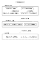
このように構成される本実施形態にかかる人体局部洗浄装置1の制御について、図3を参照しつつ詳細に説明する。制御の工程(フェーズ)は、大まかに、水源Sから供給される水をある程度まで加熱する沸き上げ工程、洗浄ノズル20のノズル部21を前進させるノズル伸ばし工程、局部洗浄用の水を使用者の局部に向けて噴出する洗浄工程に区分けされる。制御手段30は、各工程において、加熱部10に送給される水の流量の制御(流量調整バルブ40の制御)およびヒータ11の出力を制御する。
The control of the human body
沸き上げ工程における流量の制御は次の通りである。まず、流量を予め設定された沸き上げ流量に設定する。本実施形態では、流量調整バルブ40から出力される流体流量が最も大きい状態(流量大)に設定される。制御手段30は、出口温度センサ13によって測定される温度を検出し、当該温度が目標温度(使用者が設定した洗浄水の温度に基づき設定された温度をいう。以下同じ)に達したときは、冷水抜きを行う。本実施形態では、加熱部10と洗浄ノズル20の間に設けられた流量調整バルブ40(ロータリバルブ)に、水を外部に排出する流路に流体が送られるよう切り替える機能が設けられているため、当該流量調整バルブ40を制御することで冷水抜きを行う。かかる冷水抜きは、流路内に残存していた冷水が使用者にかからないようにするための処理である。流量調整バルブ40とは別のバルブ等により、当該冷水抜きが実行される構成としてもよい。
The control of the flow rate in the boiling process is as follows. First, the flow rate is set to a preset boiling flow rate. In the present embodiment, the fluid flow rate output from the flow
沸き上げ工程におけるヒータ11の制御は次の通りである。まず、ヒータ11を予め定められた初期出力値に設定する。本実施形態における初期出力値は、加熱部10に供給される流体の温度(入口温度センサ14によって検出される温度)に応じて変化させる(流体の温度に応じた複数種の初期出力値(固定値)が設定されている)。このように加熱部10に供給される流体の温度に応じて初期出力値を変化させるのは、流体の温度が高いときに初期出力値を高くするとオーバーシュートが発生してしまうおそれがあるからである。所定時間経過後、ヒータ11の出力をフィードバック制御による制御に切り替える。つまり、目標温度と出口温度センサ13によって検出される温度を比較しつつ、ヒータ11の出力を増減させる。初期出力値に固定し続ける構成とすると、外乱等の影響を受けやすいため、途中でフィードバック制御に切り替える。
The control of the
以上が本実施形態における沸き上げ工程の制御である。なお、当該制御はあくまで一例である。沸き上げ工程は、加熱部10から出力される流体の温度を、目標温度に到達させるまたは目標温度に近づけるための工程であり、そのような工程であれば具体的な制御の内容は適宜変更可能である。
The above is control of the boiling process in this embodiment. Note that this control is merely an example. The boiling process is a process for causing the temperature of the fluid output from the
上記沸き上げ工程における冷水抜きの実行後、ノズル伸ばし工程に移る。ノズル伸ばし工程は、流体圧によってノズル部21を前進させる必要があるため、加熱部10(流量調整バルブ40)から出力される流体流量は、最も大きい状態(流量大)とされる。つまり、沸き上げ工程の流量がそのまま維持される。冷水抜きを終了するということは、流体が外部に排出されずに洗浄ノズル20に送られる状態となるということであるため、当該流体の圧力により、洗浄ノズル20のノズル部21が原位置から洗浄位置に向かって前進する。
After performing the cold water removal in the boiling process, the process proceeds to the nozzle extending process. In the nozzle extension process, it is necessary to advance the
一方、ヒータ11の出力は、洗浄流量に基づく制御に切り替えられる。ここでいう洗浄流量とは、使用者が設定している洗浄ノズル20から噴出される局部洗浄用の水の噴出圧力(以下、洗浄圧と称することもある)とリンクするものである。つまり、使用者は、洗浄圧が好みのものとなるよう調整するところ、当該洗浄圧を発現するために必要な流量が洗浄流量ということになる。上記沸き上げ工程やノズル伸ばし工程は局部洗浄用の水が噴出される状態ではないため、本来であれば洗浄流量を考慮した制御を実行する工程ではないが、本実施形態におけるノズル伸ばし工程では洗浄流量に基づきヒータ11の出力を制御する。実際に加熱部10に送られる流体の流量は、ヒータ11の出力を増減させる因子としないということである。
On the other hand, the output of the
本実施形態では、予め洗浄流量に応じたヒータ11出力制御用の固定値が複数設定されており、当該複数の固定値(以下、出力調整値と称することもある)のいずれかを出力する。例えば、使用者が設定可能な局部洗浄用の水の洗浄圧として「大」「中」「小」の三段階が設定されたものであれば、洗浄流量も三段階であるということであり、当該各段階に応じた出力調整値が予め設定されている。流量に応じて、その都度適当な出力調整値を算出する構成としてもよい。いずれにせよ、本実施形態におけるノズル伸ばし工程では、沸き上げ工程で実行されていたフィードバック制御をそのまま継続しない。つまり、加熱部10から出力される温度が目標温度に近づくようヒータ11の出力を増減させるのではなく、使用者の任意の選択によって決まる洗浄流量に応じた出力に変化させる。
In the present embodiment, a plurality of fixed values for
上記ノズル伸ばし工程において、洗浄ノズル20のノズル部21が原位置から洗浄位置に到達した後、洗浄工程に移る。なお、洗浄ノズル20が洗浄位置に到達したかどうかを判断する手法はどのようなものであってもよい。センサ等によって検出してもよいし、予め設定された時間が経過したときに洗浄ノズル20が洗浄位置に到達したとみなす構成としてもよい。
In the nozzle extension process, after the
洗浄工程では、洗浄ノズル20に送られる流体の流量を洗浄流量とする。つまり、洗浄圧が、使用者が設定したものとなるよう流量を制御する。また、ヒータ11の出力をフィードバック制御による制御とする。つまり、局部洗浄用の水の温度(加熱部10から出力される流体の温度)が、使用者が設定する目標温度となるよう制御する。
In the cleaning process, the flow rate of the fluid sent to the cleaning
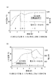
図3に示すように制御することによって生じる作用は以下の通りである。図4(a)には、本実施形態の制御を行った場合における加熱部10から出力される流体温度の変化等の一例を示す。参考(比較)として、図4(b)には、ノズル伸ばし工程中もフィードバック制御によりヒータ11の出力を制御した場合における加熱部10から出力される流体温度の変化等の一例(以下、参考例と称する)を示す。
The effect | action produced by controlling as shown in FIG. 3 is as follows. FIG. 4A illustrates an example of a change in fluid temperature output from the
図4(b)に示す参考例では、沸き上げ工程からノズル伸ばし工程に推移しても、フィードバック制御が継続される。ノズル伸ばし工程では、ノズル部21を前進させるために加熱部10(流量調整バルブ40)から出力される流体流量は最も大きい状態(流量大)とされる。加熱対象である流体の流量が大きいということは、ヒータ11の出力(電力)も大きくなる。したがって、ノズル伸ばし工程中も、ヒータ11の出力はそのまま維持されるような制御となる。その後、ノズル伸ばし工程から洗浄工程に推移したとき、流体の流量は使用者の選択によって決まる洗浄流量となる。当該洗浄流量がノズル伸ばし工程においてノズル部21を前進させるのに必要な流量よりも小さいとき、フィードバック制御によってヒータ11の出力を低下させることになる。しかし、ヒータ11の応答性が悪いと、ノズル伸ばし工程における出力(ノズル伸ばし工程で発生していた熱)が残存してしまい、流体の温度が目標温度よりも高くなってしまうおそれがある。シーズヒータのような応答性に劣るヒータを使用する場合には、その傾向が顕著となる。例えば、参考として図5に示すように、比較的応答性に優れるセラミックヒータを用いた加熱部10とした場合、ヒータの出力低下とともに出力される流体の温度が素早く低下する。一方、本実施形態のように、シーズヒータを用いた加熱部10とした場合、ヒータの出力低下時点と、出力される流体の温度の低下時点のずれが大きい。
In the reference example shown in FIG. 4B, the feedback control is continued even when the process proceeds from the boiling process to the nozzle extension process. In the nozzle extending step, the fluid flow rate output from the heating unit 10 (flow rate adjusting valve 40) to advance the
このように、参考例のような制御では、洗浄開始時に、加熱部10から出力される流体の温度と目標温度との間にずれが生じてしまうおそれがある。一方、図4(a)に示すように、本実施形態では、沸き上げ工程からノズル伸ばし工程に推移したとき、ヒータ11の出力は洗浄流量に基づいたもの(出力調整値)とされる。洗浄流量がノズル伸ばし工程においてノズル部21を前進させるのに必要な流量よりも小さいときには、ノズル伸ばし工程に推移することでヒータ11の出力は低下する。つまり、その後、ノズル伸ばし工程から洗浄工程に推移したとき(再びフィードバック制御に切り替わったとき)でも、ノズル伸ばし工程におけるヒータ11の出力は洗浄流量に基づくものであったのであるから、洗浄工程移行後に流体を加熱しすぎてしまうといったことはない。このように、本実施形態によれば、洗浄開始時に、加熱部10から出力される流体の温度と目標温度との間のずれを小さくすることができる。
Thus, in the control as in the reference example, there is a possibility that a deviation occurs between the temperature of the fluid output from the
特に、本実施形態における洗浄ノズル20は、流体圧によってノズル部21が変位する流体圧式洗浄ノズルであり、ノズル部21を洗浄位置に変位させるために洗浄開始前に流量が比較的大きくされる。したがって、当該洗浄開始前の流量は、使用者が設定した流量(洗浄圧)よりも大きくなりやすい。その場合、洗浄開始時には流量が小さくなるように変化することになるため、加熱部10から出力される流体の温度と目標温度との間のずれが大きくなりやすい。つまり、本実施形態における制御手法は、流体圧式洗浄ノズルを用いた装置において特に大きくなりやすい、加熱部10から出力される流体の温度と目標温度との間のずれを低減するものとして有効である。
In particular, the cleaning
そして、流体圧式洗浄ノズルのノズル部21が原位置から洗浄位置に変位する間、すなわちノズル伸ばし工程においては、加熱部10から出力される流体は当該ノズル部21を変位させるための動力を生じさせるものとして利用される。つまり、ノズル伸ばし工程においては、流体の温度はどのようなものであってもよい。そのため、加熱部10に送給されている流体の流量によらず、使用者が設定する洗浄流量に基づきヒータ11の出力を制御する期間は、流体の温度がどのような温度であってもよいノズル伸ばし工程に含まれるようにすることが好ましいことになる。なお、ノズル伸ばし工程の手前、すなわち沸き上げ工程の途中から、洗浄流量に基づきヒータ11の出力を制御するようにしてもよい。つまり、洗浄動作の開始前におけるある時点から洗浄動作の開始までの所定期間、加熱部10に送給されている流体の流量によらず、使用者が設定する洗浄流量に基づきヒータ11の出力を制御するようにすればよく、本実施形態のように当該所定期間がノズル伸ばし工程に含まれるようにすればさらに好ましいということである。
And while the
以上、本発明の実施形態について詳細に説明したが、本発明は上記実施形態に何ら限定されるものではなく、本発明の要旨を逸脱しない範囲で種々の改変が可能である。 As mentioned above, although embodiment of this invention was described in detail, this invention is not limited to the said embodiment at all, A various change is possible in the range which does not deviate from the summary of this invention.
上記実施形態では、洗浄ノズル20として流体圧式洗浄ノズルを用いていることを説明したが、流体圧式洗浄ノズルを用いた装置に上記制御手法を適用することが特に有効であるということであって、電気的駆動源(例えばモータ)等によって駆動する洗浄ノズルを用いた装置に対しても同様の制御手法を適用することができる。この種の装置においても、洗浄動作の開始前におけるある時点から洗浄動作の開始までの所定期間、加熱部10に送給されている流体の流量によらず、使用者が設定する洗浄流量に基づきヒータ11の出力を制御するようにすればよい。
In the above embodiment, it has been described that a fluid pressure type cleaning nozzle is used as the cleaning
上記実施形態では、ヒータ11としてシーズヒータを用いていることを説明したが、このような応答性の悪いヒータを用いた装置に上記制御手法を適用することが特に有効であるということであって、どのようなヒータ11であっても出力を増減させた際に多少の応答の遅れは生じるものであるから、その他のヒータを用いた装置に対しても同様の制御手法を適用することができる。
In the above embodiment, it has been described that a sheathed heater is used as the
1 人体局部洗浄装置
10 加熱部
11 ヒータ
13 出口温度センサ
14 入口温度センサ
20 洗浄ノズル
21 ノズル部
211 噴出口
22 シリンダ
30 制御手段
40 流量調整バルブ
DESCRIPTION OF
Claims (4)
前記加熱部から送られた流体を噴出させる局部洗浄動作を実行する洗浄ノズルと、
前記洗浄ノズルによる局部洗浄動作の開始前におけるある時点から局部洗浄動作の開始までの所定期間、前記加熱部に送給されている流体の流量によらず、使用者が設定する洗浄流量に基づき前記ヒータの出力を制御する制御手段と、
を備える、人体局部洗浄装置。 A heating unit having a heater for heating the fluid;
A cleaning nozzle for performing a local cleaning operation for ejecting the fluid sent from the heating unit;
The predetermined period from the start of the local cleaning operation by the cleaning nozzle to the start of the local cleaning operation, regardless of the flow rate of the fluid fed to the heating unit, based on the cleaning flow rate set by the user Control means for controlling the output of the heater;
A human body local cleaning device.
Priority Applications (1)
| Application Number | Priority Date | Filing Date | Title |
|---|---|---|---|
| JP2015249190A JP6716904B2 (en) | 2015-12-22 | 2015-12-22 | Human body local cleaning device |
Applications Claiming Priority (1)
| Application Number | Priority Date | Filing Date | Title |
|---|---|---|---|
| JP2015249190A JP6716904B2 (en) | 2015-12-22 | 2015-12-22 | Human body local cleaning device |
Publications (2)
| Publication Number | Publication Date |
|---|---|
| JP2017115332A true JP2017115332A (en) | 2017-06-29 |
| JP6716904B2 JP6716904B2 (en) | 2020-07-01 |
Family
ID=59233757
Family Applications (1)
| Application Number | Title | Priority Date | Filing Date |
|---|---|---|---|
| JP2015249190A Active JP6716904B2 (en) | 2015-12-22 | 2015-12-22 | Human body local cleaning device |
Country Status (1)
| Country | Link |
|---|---|
| JP (1) | JP6716904B2 (en) |
Cited By (2)
| Publication number | Priority date | Publication date | Assignee | Title |
|---|---|---|---|---|
| KR101961635B1 (en) * | 2017-09-28 | 2019-03-25 | 토토 가부시키가이샤 | Sanitary washing device |
| JP2020033830A (en) * | 2018-08-31 | 2020-03-05 | Toto株式会社 | Sanitary washing equipment |
Citations (9)
| Publication number | Priority date | Publication date | Assignee | Title |
|---|---|---|---|---|
| JPS6131540A (en) * | 1984-07-23 | 1986-02-14 | 松下電器産業株式会社 | sanitary cleaning equipment |
| JP2001132052A (en) * | 1999-10-29 | 2001-05-15 | Toto Ltd | Human body cleaning device |
| JP2003213765A (en) * | 2002-01-24 | 2003-07-30 | Matsushita Electric Ind Co Ltd | Sanitary washing equipment |
| JP2004232401A (en) * | 2003-01-31 | 2004-08-19 | Toto Ltd | Sanitary washing device |
| JP2005054456A (en) * | 2003-08-05 | 2005-03-03 | Matsushita Electric Ind Co Ltd | Human body local cleaning device and toilet device equipped with the same |
| KR100809476B1 (en) * | 2007-01-29 | 2008-03-03 | 위니아만도 주식회사 | Bidet and bidet hot water module control method |
| JP2011214233A (en) * | 2010-03-31 | 2011-10-27 | Toto Ltd | Sanitary washing device |
| KR20140025985A (en) * | 2012-08-24 | 2014-03-05 | 주식회사 교원 | Monitoring system for a hot-water tank of a water purifier and a method of monitoring using the same |
| JP2015048593A (en) * | 2013-08-30 | 2015-03-16 | アイシン精機株式会社 | Human body private part washing device |
-
2015
- 2015-12-22 JP JP2015249190A patent/JP6716904B2/en active Active
Patent Citations (9)
| Publication number | Priority date | Publication date | Assignee | Title |
|---|---|---|---|---|
| JPS6131540A (en) * | 1984-07-23 | 1986-02-14 | 松下電器産業株式会社 | sanitary cleaning equipment |
| JP2001132052A (en) * | 1999-10-29 | 2001-05-15 | Toto Ltd | Human body cleaning device |
| JP2003213765A (en) * | 2002-01-24 | 2003-07-30 | Matsushita Electric Ind Co Ltd | Sanitary washing equipment |
| JP2004232401A (en) * | 2003-01-31 | 2004-08-19 | Toto Ltd | Sanitary washing device |
| JP2005054456A (en) * | 2003-08-05 | 2005-03-03 | Matsushita Electric Ind Co Ltd | Human body local cleaning device and toilet device equipped with the same |
| KR100809476B1 (en) * | 2007-01-29 | 2008-03-03 | 위니아만도 주식회사 | Bidet and bidet hot water module control method |
| JP2011214233A (en) * | 2010-03-31 | 2011-10-27 | Toto Ltd | Sanitary washing device |
| KR20140025985A (en) * | 2012-08-24 | 2014-03-05 | 주식회사 교원 | Monitoring system for a hot-water tank of a water purifier and a method of monitoring using the same |
| JP2015048593A (en) * | 2013-08-30 | 2015-03-16 | アイシン精機株式会社 | Human body private part washing device |
Cited By (5)
| Publication number | Priority date | Publication date | Assignee | Title |
|---|---|---|---|---|
| KR101961635B1 (en) * | 2017-09-28 | 2019-03-25 | 토토 가부시키가이샤 | Sanitary washing device |
| US10364562B2 (en) | 2017-09-28 | 2019-07-30 | Toto Ltd. | Sanitary washing device |
| EP3461961B1 (en) | 2017-09-28 | 2020-06-10 | Toto Ltd. | Sanitary washing device |
| JP2020033830A (en) * | 2018-08-31 | 2020-03-05 | Toto株式会社 | Sanitary washing equipment |
| JP7115153B2 (en) | 2018-08-31 | 2022-08-09 | Toto株式会社 | sanitary washing equipment |
Also Published As
| Publication number | Publication date |
|---|---|
| JP6716904B2 (en) | 2020-07-01 |
Similar Documents
| Publication | Publication Date | Title |
|---|---|---|
| JP6107422B2 (en) | Heat exchange unit and local body cleaning device | |
| EP3160613B1 (en) | Home appliance | |
| CN1756930B (en) | Heating device and sanitary flushing device using the same | |
| JP6716904B2 (en) | Human body local cleaning device | |
| KR101407203B1 (en) | Injection molding machine | |
| KR20120027184A (en) | Method for controlling a continuous flow heater | |
| WO2016080039A1 (en) | Liquid heater | |
| EP3288336B1 (en) | Sanitary washing device | |
| KR20070107531A (en) | Hot water temperature control method of hot water cleaner | |
| JP7009883B2 (en) | Local cleaning equipment | |
| JP7287121B2 (en) | Warm water washing toilet seat device | |
| JP4775900B2 (en) | Faucet device | |
| JPH1060981A (en) | Hot water temperature control device for sanitary washing device | |
| JP4071509B2 (en) | Toilet equipment | |
| JP4457476B2 (en) | Sanitary washing device | |
| JP6980339B2 (en) | Liquid material discharge device and liquid material discharge method | |
| JP5667587B2 (en) | Heating device | |
| JP6746098B2 (en) | Sanitary washing equipment | |
| JP2014177045A5 (en) | ||
| JP5948804B2 (en) | Faucet device | |
| JP4071508B2 (en) | Toilet equipment | |
| JP3883450B2 (en) | Toilet equipment | |
| WO2016063568A1 (en) | Liquid heating device | |
| JP6331706B2 (en) | Fluid heating device | |
| JP4759814B2 (en) | Sanitary washing device |
Legal Events
| Date | Code | Title | Description |
|---|---|---|---|
| A621 | Written request for application examination |
Free format text: JAPANESE INTERMEDIATE CODE: A621 Effective date: 20181107 |
|
| A977 | Report on retrieval |
Free format text: JAPANESE INTERMEDIATE CODE: A971007 Effective date: 20190911 |
|
| A131 | Notification of reasons for refusal |
Free format text: JAPANESE INTERMEDIATE CODE: A131 Effective date: 20190924 |
|
| A521 | Request for written amendment filed |
Free format text: JAPANESE INTERMEDIATE CODE: A523 Effective date: 20191122 |
|
| TRDD | Decision of grant or rejection written | ||
| A01 | Written decision to grant a patent or to grant a registration (utility model) |
Free format text: JAPANESE INTERMEDIATE CODE: A01 Effective date: 20200512 |
|
| A61 | First payment of annual fees (during grant procedure) |
Free format text: JAPANESE INTERMEDIATE CODE: A61 Effective date: 20200525 |
|
| R151 | Written notification of patent or utility model registration |
Ref document number: 6716904 Country of ref document: JP Free format text: JAPANESE INTERMEDIATE CODE: R151 |
|
| S533 | Written request for registration of change of name |
Free format text: JAPANESE INTERMEDIATE CODE: R313533 |
|
| R350 | Written notification of registration of transfer |
Free format text: JAPANESE INTERMEDIATE CODE: R350 |
|
| S111 | Request for change of ownership or part of ownership |
Free format text: JAPANESE INTERMEDIATE CODE: R313113 |
|
| R350 | Written notification of registration of transfer |
Free format text: JAPANESE INTERMEDIATE CODE: R350 |