JP2017115532A - Fence mounting structure - Google Patents
Fence mounting structure Download PDFInfo
- Publication number
- JP2017115532A JP2017115532A JP2015254894A JP2015254894A JP2017115532A JP 2017115532 A JP2017115532 A JP 2017115532A JP 2015254894 A JP2015254894 A JP 2015254894A JP 2015254894 A JP2015254894 A JP 2015254894A JP 2017115532 A JP2017115532 A JP 2017115532A
- Authority
- JP
- Japan
- Prior art keywords
- fence
- fitting
- locking
- end side
- groove
- Prior art date
- Legal status (The legal status is an assumption and is not a legal conclusion. Google has not performed a legal analysis and makes no representation as to the accuracy of the status listed.)
- Granted
Links
Images




Landscapes
- Fencing (AREA)
Abstract
【課題】専用工具を用いずに、メッシュフェンスと支柱を容易に接続することを可能にするフェンスの取付構造を提供する。【解決手段】支柱1にメッシュフェンス2を取付けるための取付構造Aであって、メッシュフェンス2の横筋2bあるいは縦筋2aに係止させつつ支柱1に貫通形成される挿通孔1aに挿通して配設される係止部10と、挿通孔1aに挿通された係止部10の先端側に係合する嵌合部11とを備える。また、係止部10は嵌合部11が係合する溝部を備え、嵌合部11は係止部10を挿通して溝部に係合する係合孔部を備えるとともに、溝部に係合孔部を係合させた状態で支柱1に係止される支柱係止部11cを備える。【選択図】図1An object of the present invention is to provide a fence mounting structure that makes it possible to easily connect a mesh fence and a post without using a special tool. [Solution] A mounting structure A for attaching a mesh fence 2 to a post 1, in which the mesh fence 2 is inserted into an insertion hole 1a formed through the post 1 while being engaged with a horizontal strip 2b or a vertical strip 2a of the mesh fence 2. It includes a locking part 10 and a fitting part 11 that engages with the distal end side of the locking part 10 inserted into the insertion hole 1a. Further, the locking part 10 includes a groove in which the fitting part 11 engages, and the fitting part 11 includes an engagement hole in which the locking part 10 is inserted and engages with the groove. A post locking part 11c is provided which is locked to the post 1 in a state where the parts are engaged with each other. [Selection diagram] Figure 1
Description
本発明は、フェンスの取付構造に関し、特に、支柱とフェンス本体を接続して固定するための構造に関する。 The present invention relates to a fence mounting structure, and more particularly to a structure for connecting and fixing a column and a fence body.
従来、敷地の外周などにフェンスを設置し、敷地境界の明確化、敷地内の視認制限などを図るようにしている。 Conventionally, fences have been installed on the outer periphery of the site to clarify the boundary of the site and limit the visibility of the site.
この種のフェンスには、所定の間隔をあけて立設された複数の支柱1と、複数の支柱1に支持させてフェンス面を形成するように並設される複数のフェンス本体2とを備えて構成したものがある。また、フェンス本体2として縦筋(縦線材)2aと横筋(横線材)2bを格子状に組み付けてなるメッシュフェンスが多用されている(図23参照)。
This type of fence includes a plurality of
ここで、例えば、メッシュフェンス2をフェンス本体として用いる場合には、図23及び図24に示すように、棒状の軸部3aの先端にフック部3bを備えたフックボルト3を固定手段4として用い、メッシュフェンス2を支柱1に接続して固定する。すなわち、フック部3bを横筋2bに引っ掛けて係合させつつ軸部3aを支柱1に貫通形成されたボルト挿通孔1aに挿通してフックボルト3を取り付け、支柱1の側面から突出した軸部3aの先端側にナット5を締結することにより、メッシュフェンス2を支柱1に固定するようにしている。
Here, for example, when the
しかしながら、上記従来のフェンスの取付構造の固定手段は、フックボルト、ナットを用いるため、取付作業に専用工具が必要であり、フェンスが大きくなるほど、若しくは設置個数が増えるほど、その取付作業に多大な手間と労力、ひいては多大なコストを要することになる。 However, since the fixing means of the conventional fence mounting structure uses hook bolts and nuts, a dedicated tool is required for the mounting work. The larger the fence or the greater the number of installations, the greater the mounting work. It takes a lot of labor and labor, and therefore a great deal of cost.
また、専用工具を使うため、その取付作業を職人が行っており、将来的な職人不足に対応するため、熟練作業員でなくても容易に且つ好適にフェンスの取付作業を行えるようにすることが強く望まれている。 In addition, since dedicated tools are used, the craftsmen perform the installation work, and in order to cope with the future shortage of craftsmen, it is possible to easily and suitably perform the fence installation work even if it is not a skilled worker. Is strongly desired.
さらに、フックボルトを支柱に先付けしてからフェンス本体を取り付けようとすると、支柱の挿通孔に挿通したフックボルトが回転し、フック部が下を向いてしまう場合があり、この場合にはフェンス本体を引っ掛けることができず、この点からも取付作業に多大な手間と労力を要することになる。 In addition, if you try to attach the fence body after attaching the hook bolt to the support, the hook bolt inserted through the insertion hole of the support may rotate and the hook part may face downward. From this point, too much labor and labor are required for the mounting work.
本発明は、上記事情に鑑み、専用工具を用いずに、メッシュフェンスと支柱を容易に接続することを可能にするフェンスの取付構造を提供することを目的とする。 In view of the above circumstances, an object of the present invention is to provide a fence attachment structure that enables easy connection between a mesh fence and a support column without using a dedicated tool.
上記の目的を達するために、この発明は以下の手段を提供している。 In order to achieve the above object, the present invention provides the following means.
本発明のフェンスの取付構造は、支柱にメッシュフェンスを取付けるための取付構造であって、前記メッシュフェンスの横筋あるいは縦筋に係止させつつ前記支柱に貫通形成される挿通孔に挿通して配設される係止部と、前記挿通孔に挿通された前記係止部の先端側に係合する嵌合部とを備えており、前記係止部は前記嵌合部が係合する溝部を備え、前記嵌合部は前記係止部を挿通して前記溝部に係合する係合孔部を備えるとともに、前記溝部に前記係合孔部を係合させた状態で前記支柱に係止される支柱係止部を備えることを特徴とする。 The fence attachment structure of the present invention is an attachment structure for attaching a mesh fence to a support column, and is inserted into an insertion hole formed through the support column while being locked to a horizontal stripe or a vertical stripe of the mesh fence. A locking portion that is provided, and a fitting portion that engages with a distal end side of the locking portion that is inserted through the insertion hole, and the locking portion includes a groove portion that engages with the fitting portion. The engagement portion includes an engagement hole portion that is inserted through the engagement portion and engages with the groove portion, and is engaged with the support column in a state where the engagement hole portion is engaged with the groove portion. It is provided with the support | pillar latching | locking part.
また、本発明のフェンスの取付構造においては、前記支柱と前記嵌合部の間に挿入して前記嵌合部を押圧するように配設される保持部を備えており、前記係止部は、前記溝部が形成された部分の先端側に厚さが大きい厚肉部、前記溝部が形成された部分の後端側に前記厚肉部よりも厚さが小さい薄肉部を備えて形成され、前記嵌合部は、前記係止部を挿通する係合孔部を備えるとともに、前記係止部の前記薄肉部よりも前記係合孔部の幅寸法を大きくし、前記厚肉部よりも前記係合孔部の幅寸法を小さくする引き抜け防止部を備えて形成されていてもよい。 Further, in the fence mounting structure of the present invention, it is provided with a holding portion disposed so as to be inserted between the support column and the fitting portion and press the fitting portion, A thick portion having a large thickness on the leading end side of the portion where the groove portion is formed, and a thin portion having a smaller thickness than the thick portion on the rear end side of the portion where the groove portion is formed, The fitting portion includes an engagement hole portion through which the engagement portion is inserted, and has a larger width dimension of the engagement hole portion than the thin portion of the engagement portion, and more than the thick portion. It may be provided with a pull-out prevention part that reduces the width dimension of the engagement hole part.
本発明のフェンスの取付構造においては、専用工具を用いずに、メッシュフェンスと支柱を容易に接続して固定することが可能になる。 In the fence mounting structure of the present invention, the mesh fence and the support can be easily connected and fixed without using a dedicated tool.
以下、図1から図23を参照し、本発明の一実施形態に係るフェンスの取付構造について説明する。 Hereinafter, a fence mounting structure according to an embodiment of the present invention will be described with reference to FIGS. 1 to 23.
はじめに、本実施形態のフェンスは、例えば、敷地の外周などに設置し、敷地境界の明確化、敷地内の視認制限などを図るためのものであり、所定の間隔をあけて立設された複数の支柱1と、複数の支柱1に支持させてフェンス面を形成するように並設される複数のフェンス本体2とを備えて構成されている(図23参照)。
First, the fence according to the present embodiment is installed, for example, on the outer periphery of a site, for the purpose of clarifying the boundary of the site, limiting the visibility in the site, and the like. And a plurality of
また、本実施形態では、図23に示すように、フェンス本体として縦筋2aと横筋2bを格子状に組み付けてなるメッシュフェンス2が用いられている。さらに、このメッシュフェンス2は、縦筋2aを円弧状に形成するなどして、その上部側が胴縁状に形成されている。
Further, in the present embodiment, as shown in FIG. 23, a
次に、本実施形態のフェンスの取付構造Aは、図1から図3に示すように、支柱1にメッシュフェンス2を固定するための構造であり、所定の間隔をあけて立設される複数の支柱1と、各支柱1の一側面から反対側の他側面に貫通する挿通孔1aと、メッシュフェンス2の横筋2b(あるいは縦筋2a)に係止させつつ挿通孔1aに挿通し、支柱1の他側面から先端側を突出して配設される係止部材(係止部)10と、係止部材10の支柱1の他側面から突出した先端側に取り付けられて係止部材10が挿通孔1aから引き抜けることを防止するための嵌合部材(嵌合部)11と、嵌合部材11を保持するための保持部材(保持部)12とを備えて構成されている。
Next, as shown in FIG. 1 to FIG. 3, the fence attachment structure A of the present embodiment is a structure for fixing the
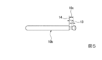
本実施形態の係止部材10は、図4、図5(図1から図3)に示すように、円弧状に形成され、後端側に設けられたフック部(係止部)10aと、フック部10aから直線状に延設された軸部10bとを備えて形成されている。
As shown in FIGS. 4 and 5 (FIGS. 1 to 3), the
軸部10bは、例えば円柱棒状に形成され、その先端側に、軸部10bの軸線中心の径方向両側に対称配置され、外面から径方向内側に凹み、軸部10bを水平方向に配した状態で上下方向に延びて略半円状を呈するように形成された一対の溝部10cを備えて形成されている。
The
さらに、本実施形態の軸部10bの一対の溝部10cは、これら一対の溝部10cが形成された部分の厚さが先端側よりも後端側を小にして形成されている。言い換えれば、軸部10bの溝部10cは、その深さが先端側よりも後端側を大にして形成され、これにより、一対の溝部10cが形成された部分には、先端側にその溝の深さが浅く、軸部10bの厚さ(太さ)が大きい厚肉部13が設けられ、厚肉部13よりも後端側に溝の深さが深く、軸部の厚さ(太さ)が小さい薄肉部14が設けられている。
Further, the pair of
嵌合部材11は、図6、図7、図8(図1から図3)に示すように、略板状に形成されて横方向に突出する押圧部11aと、押圧部11aに上端を繋げ、下方に延出する略板状の本体部11bと、本体部11bの両側部に繋がり、本体部11bに直交し、押圧部11aの突出方向と逆方向に突出する略板状の支柱係止部11cとを備えている。
As shown in FIGS. 6, 7, and 8 (FIGS. 1 to 3), the
押圧部11aには、幅方向略中央に突出方向先端から基端に向けて凹む指掛け孔11dが設けられている。
The
本体部11bは、幅方向中央に、一面から他面に貫通し、下端側から上端側に延びる係合孔部11eを備えて形成されている。
The
また、係合孔部11eの上端部側の幅が係止部材10の軸部10bの外径よりも小さく、一対の溝部10cが形成された部分の厚肉部13の厚さと同等あるいは僅かに大きな寸法で形成され、この部分が保持部11fとされている。
Further, the width on the upper end portion side of the
さらに、係合孔部11eの保持部11fよりも下方の部分に、係合孔部11eの保持部11f及び下端側よりも幅寸法を小にした引き抜け防止部(絞り部)11gが設けられている。また、この引き抜け防止部11gが設けられた部分の係合孔部11eの幅は、軸部10bの薄肉部14の厚さよりも大きく、厚肉部13の厚さよりも小さな寸法とされている。
Furthermore, a pull-out preventing portion (throttle portion) 11g having a smaller width than the holding
また、本体部11bには、一面から他面に貫通し、後述の保持部材12の板バネ部12bの凸部15が係合する凹部16が形成されている。
The
保持部材12は、図9、図10、図11(図1から図3)に示すように、横方向に突出する押圧部12aと、押圧部12aに上端を繋げ、下方に延出する板バネ部(付勢押圧部)12bとを備えて、側面視逆L字状の略板状に形成されている。また、板バネ部12bは、押圧部12aに繋がる上端と下端の間の中間部が押圧部12aの延出方向と同方向の横方向に屈曲して膨出に、側面視弓状に形成されている。
As shown in FIGS. 9, 10, and 11 (FIGS. 1 to 3), the holding
さらに、板バネ部12bは、幅方向中央に下端から上端側に凹む係合凹部(係合孔部)12cを備え、この係合凹部12cを挟んで幅方向両側に上端側から下端に延びる一対の板バネ片12dを備えて正面視略U字状に形成されている。
Further, the
また、保持部材12には、板バネ部12bに嵌合部材11の本体部11bの凹部16に係合する凸部15が設けられている。
Further, the holding
そして、本実施形態のフェンスの取付構造Aを用いてメッシュフェンス2を取り付ける際には、図1から図3に示すように、まず、軸部10bを支柱1の一側面側から挿通孔1aに挿通させて係止部材10を配設する。
And when attaching the
次に、支柱1の他側面に突出した係止部材10の軸部10bの先端側を係合孔部11eに挿通しつつ、軸部10bの一対の溝部10cの薄肉部14に保持部11fを係合させて嵌合部材11を配設する。このとき、嵌合部材11に一対の支柱係止部11cが設けられているため、これら一対の支柱係止部11cの間に支柱1を嵌合させるようにして嵌合部材11が配設される。これにより、各支柱係止部11cが支柱1の側面に係合することになり、嵌合部材11、さらにこの嵌合部材11が溝部10cに係合した係止部材10が回転することがない。
Next, the holding
そして、係止部材10のフック部10aが所定の方向で保持された状態で、フック部10aにメッシュフェンス2の横筋2b(あるいは縦筋2a)を引っ掛け、メッシュフェンスを配設する。
Then, with the
次に、支柱1の他側面と嵌合部材11の間に、保持部材12を設置する。このとき、係止部材10の軸部10bの先端側の一対の溝部10cの薄肉部14に一対の板バネ片12dを係合させて保持部材12を配設する。また、指などで押圧部12aを上方から下方に押圧し、軸部10bの一対の溝部10cに一対の板バネ片12dを押し込んでゆき、軸部10bを係合凹部12cに挿通させる。
Next, the holding
このように保持部材12を設置すると、先行して取り付けられた嵌合部材11が保持部材12の板バネ部12bに押圧されて係止部材10の軸部10bの厚肉部13にスライド移動し、さらに嵌合部材11によって係止部材10が軸部10bを支柱1の挿通孔1aにさらに挿通させるように引っ張られる。これにより、保持部材の板バネ部に付勢されて嵌合部材が軸部を引っ張った状態で保持され、係止部材のフック部で係止されたメッシュフェンスもさらに支柱に近づいてしっかりと固定して保持される。
When the holding
ここで、上記のように、保持部材12を設置し、係止部材10の一対の溝部10cが形成された部分の薄肉部14に係合していた嵌合部材11が保持部材12に押圧されて厚肉部13にスライド移動する。また、嵌合部材11には引き抜け防止部11gが設けられ、この引き抜け防止部11gが設けられた部分の係合孔部11eがその幅を軸部10bの薄肉部14の厚さよりも大きく、厚肉部13の厚さよりも小さな寸法にして形成されている。このため、保持部材12を設置するとともに、厚肉部13にスライド移動した嵌合部材11が、引き抜け防止部11gによって引き抜け不能な状態で自動的に保持されることになる。
Here, as described above, the holding
したがって、本実施形態のフェンスの取付構造Aにおいては、軸部10bを支柱1の挿通孔1aに挿通して係止部材10を配設し、この係止部材10の軸部10bに設けられた一対の溝部10cに嵌合部材11を係合させることにより、嵌合部材11の支柱係止部11cが支柱1に係止され、嵌合部材11ひいては係止部材10が回転しないように保持することができる。
Therefore, in the fence mounting structure A of the present embodiment, the locking
これにより、メッシュフェンス2にフック部10aを容易に引っ掛けて設置することができる。すなわち、フックボルトの係止部材10を支柱1に先付けしてからメッシュフェンス2を組み付けることができる。また、このとき、従来、支柱1に付いていたメッシュフェンス仮設置用の「仮止めフック」を不要にして取付作業を行うことが可能になる。
Thereby, the
また、支柱1の他側面と嵌合部材11の間に保持部材12を指などで押し込んで取り付けることによって、メッシュフェンス2を支柱1に固定することができる。
In addition, the
よって、本実施形態のフェンスの取付構造Aによれば、メッシュフェンス2に係止させて支柱1の挿通孔1aに挿通配置した係止部材10に係合させて嵌合部材11と保持部材12を押し込むという簡易な操作によって、メッシュフェンス2と支柱1を容易に接続することが可能になる。すなわち、従来のように専用工具を用いずに、メッシュフェンス2と支柱1を容易に接続することが可能になる。
Therefore, according to the fence attachment structure A of the present embodiment, the
これにより、従来のフェンスの取付構造と比較し、取付作業の手間と労力を大幅に軽減してメッシュフェンス2を支柱1に接続固定することができ、ひいては大幅に施工コストを削減することが可能になる。
As a result, compared with the conventional fence mounting structure, it is possible to greatly reduce the labor and labor of the mounting work, and to connect and fix the
また、本実施形態のフェンスの取付構造Aにおいては、係止部材10の軸部10bの一対の溝部10cが形成された部分に厚肉部13と薄肉部14が設けられ、且つ、嵌合部材11の係合凹部11eの保持部11fよりも下方の部分に、係合凹部11eの保持部11f及び下端側よりも幅寸法を小にした引き抜け防止部(絞り部)11gを設けて嵌合部材11が形成されている。
Further, in the fence attachment structure A of the present embodiment, the
このため、保持部材12を設置すると、係止部材10の一対の溝部10cが形成された部分の薄肉部14に係合していた嵌合部材11が保持部材12に押圧されて厚肉部13にスライド移動し、この嵌合部材11を引き抜け防止部11gによって引き抜け不能な状態で自動的に保持することが可能になる。
For this reason, when the holding
これにより、作業者が保持部材12の押圧部12aを上方に押し上げて取り外す操作をしなければ、嵌合部材11が係止部材10から外れることがなく、係止部材10ひいてはメッシュフェンス2が支柱1に固着した状態を確実に維持することが可能になる。
As a result, if the operator does not perform an operation of pushing the
さらに、嵌合部材11を係止部材10の先端側の溝部10cに係合させ、軸部10bを保持部11fに配し、保持部材12を嵌合させるとともに保持部材12の凸部15が嵌合部材11の凹部16に係合することによって、保持部材12の引き抜けを防止することができ、結果として嵌合部材11の引き抜けをさらに確実に防止することができる。
Further, the
以上、本発明に係るフェンスの取付構造の一実施形態について説明したが、本発明は上記の一実施形態に限定されるものではなく、その趣旨を逸脱しない範囲で適宜変更可能である。 As mentioned above, although one Embodiment of the attachment structure of the fence which concerns on this invention was described, this invention is not limited to said one Embodiment, It can change suitably in the range which does not deviate from the meaning.
例えば、本実施形態では、嵌合部材11と保持部材12とによって係止部材10を固定保持するものとしたが、嵌合部材11のみで係止部材10を保持するようにしてもよい。すなわち、図12から図14に示すように、嵌合部材11の係合孔部11eに係止部材10の先端側を挿通するとともに溝部10cに係合させることによって、係止部材10を着脱可能に保持するようにしてもよい。この場合においても、本実施形態の作用効果を得ることができる。
For example, in this embodiment, the locking
例えば、本実施形態では、嵌合部材11と保持部材12が個別の部材であるものとしたが、図15から図22に示すように、嵌合部材11と保持部材12をスライド自在に一体に接続する係止片12eを設けるようにし、嵌合部材11を係止部材10の軸部10bの溝部10cに嵌合させた後、嵌合部材11にスライド自在に接続された保持部材12をスライドさせて嵌合部材11と支柱1の間に嵌め込んで係止部材10を保持するように構成してもよい。
For example, in this embodiment, the
この場合には、本実施形態のように嵌合部材11と保持部材12の2つの部材をそれぞれ個別に嵌め込むのに対し、嵌合部材11を嵌め込み、保持部材12をスライドさせるだけで係止部材10を保持することができ、また、保持部材12をスライドさせて外し、嵌合部材11を引き抜くだけで係止部材10の係止状態を解除することができ、操作性、作業性をより高めることが可能になる。
In this case, the two members of the
また、嵌合部材11が、幅方向中央に一面から他面に貫通し下端側から上端側に延びる係合孔部11eを備え、この係合孔部11eに係止部材10の軸部10bを挿通して嵌合部材11を取り付けるように説明した。これに対し、保持部材12と同様に、嵌合部材11を、幅方向中央に下端から上端側に凹む係合凹部(係合孔部)を備え、この係合凹部を挟んで幅方向両側に上端側から下端に延びる一対の保持片を備えて略U字状に形成してもよい。
In addition, the
1 支柱
1a 挿通孔
2 メッシュフェンス(フェンス本体)
2a 縦筋
2b 横筋
3 フックボルト
3a 軸部
3b フック部
4 固定手段
5 ナット
10 係止部材
10a フック部(係止部)
10b 軸部
10c 溝部
11 嵌合部材
11a 押圧部
11b 本体部
11c 支柱係止部
11d 指掛け孔
11e 係合孔部
11f 保持部
11g 引き抜け防止部(絞り部)
12 保持部材
12a 押圧部
12b 板バネ部
12c 係合凹部(係合孔部)
12d 板バネ片
12e 係止片
13 厚肉部
14 薄肉部
15 凸部
16 凹部
A フェンスの取付構造
O1 支柱の軸線
1
12
12d
Claims (2)
前記メッシュフェンスの横筋あるいは縦筋に係止させつつ前記支柱に貫通形成される挿通孔に挿通して配設される係止部と、
前記挿通孔に挿通された前記係止部の先端側に係合する嵌合部とを備えており、
前記係止部は前記嵌合部が係合する溝部を備え、
前記嵌合部は前記係止部を挿通して前記溝部に係合する係合孔部を備えるとともに、前記溝部に前記係合孔部を係合させた状態で前記支柱に係止される支柱係止部を備えることを特徴とするフェンスの取付構造。 An attachment structure for attaching a mesh fence to a support,
A locking portion that is disposed by being inserted through an insertion hole that is formed through the support column while being locked to the horizontal or vertical stripe of the mesh fence,
A fitting portion that engages with the distal end side of the locking portion inserted through the insertion hole,
The locking portion includes a groove portion with which the fitting portion is engaged,
The fitting portion includes an engagement hole portion that is inserted through the locking portion and engages with the groove portion, and a column that is locked to the column in a state where the engagement hole portion is engaged with the groove portion. A fence mounting structure comprising a locking portion.
前記支柱と前記嵌合部の間に挿入して前記嵌合部を押圧するように配設される保持部を備えており、
前記係止部は、前記溝部が形成された部分の先端側に厚さが大きい厚肉部、前記溝部が形成された部分の後端側に前記厚肉部よりも厚さが小さい薄肉部を備えて形成され、
前記嵌合部は、前記係止部を挿通する係合孔部を備えるとともに、前記係止部の前記薄肉部よりも前記係合孔部の幅寸法を大きくし、前記厚肉部よりも前記係合孔部の幅寸法を小さくする引き抜け防止部を備えて形成されていることを特徴とするフェンスの取付構造。 In the fence mounting structure according to claim 1,
A holding part disposed between the support column and the fitting part to be inserted and pressed against the fitting part;
The locking portion includes a thick portion having a large thickness on the leading end side of the portion where the groove portion is formed, and a thin portion having a smaller thickness than the thick portion on the rear end side of the portion where the groove portion is formed. Formed with
The fitting portion includes an engagement hole portion through which the engagement portion is inserted, and has a larger width dimension of the engagement hole portion than the thin portion of the engagement portion, and more than the thick portion. A fence mounting structure, characterized in that it is provided with a pull-out prevention part for reducing the width dimension of the engagement hole part.
Priority Applications (1)
| Application Number | Priority Date | Filing Date | Title |
|---|---|---|---|
| JP2015254894A JP6713769B2 (en) | 2015-12-25 | 2015-12-25 | Fence mounting structure |
Applications Claiming Priority (1)
| Application Number | Priority Date | Filing Date | Title |
|---|---|---|---|
| JP2015254894A JP6713769B2 (en) | 2015-12-25 | 2015-12-25 | Fence mounting structure |
Publications (2)
| Publication Number | Publication Date |
|---|---|
| JP2017115532A true JP2017115532A (en) | 2017-06-29 |
| JP6713769B2 JP6713769B2 (en) | 2020-06-24 |
Family
ID=59231509
Family Applications (1)
| Application Number | Title | Priority Date | Filing Date |
|---|---|---|---|
| JP2015254894A Active JP6713769B2 (en) | 2015-12-25 | 2015-12-25 | Fence mounting structure |
Country Status (1)
| Country | Link |
|---|---|
| JP (1) | JP6713769B2 (en) |
Citations (3)
| Publication number | Priority date | Publication date | Assignee | Title |
|---|---|---|---|---|
| JPH1013101A (en) * | 1996-06-20 | 1998-01-16 | Nisshin Denki Seisakusho:Kk | Connection device for flanged pipe |
| JP2006207333A (en) * | 2005-01-31 | 2006-08-10 | Toyo Exterior Co Ltd | Grid fence |
| EP1712711A1 (en) * | 2005-04-14 | 2006-10-18 | Betafence Holding NV | Fencing system |
-
2015
- 2015-12-25 JP JP2015254894A patent/JP6713769B2/en active Active
Patent Citations (3)
| Publication number | Priority date | Publication date | Assignee | Title |
|---|---|---|---|---|
| JPH1013101A (en) * | 1996-06-20 | 1998-01-16 | Nisshin Denki Seisakusho:Kk | Connection device for flanged pipe |
| JP2006207333A (en) * | 2005-01-31 | 2006-08-10 | Toyo Exterior Co Ltd | Grid fence |
| EP1712711A1 (en) * | 2005-04-14 | 2006-10-18 | Betafence Holding NV | Fencing system |
Also Published As
| Publication number | Publication date |
|---|---|
| JP6713769B2 (en) | 2020-06-24 |
Similar Documents
| Publication | Publication Date | Title |
|---|---|---|
| US9534709B2 (en) | Plumbing bracket assembly | |
| CA2984852C (en) | Electrical box bar hanger | |
| JP2017115532A (en) | Fence mounting structure | |
| JP6553503B2 (en) | Fence mounting structure | |
| JP2017040147A (en) | Fence fitting structure | |
| JPH0562542A (en) | Wire harness assembly jig | |
| JP2010095971A (en) | Mounting implement for sheet pile fall prevention fence | |
| JP2009074305A (en) | Mounting bracket for base material for steady rest | |
| KR101776212B1 (en) | Anchor bolt cap dropping prevention device | |
| JP6633784B2 (en) | Fence mounting structure | |
| JP6251711B2 (en) | Fitting prevention mounting bracket | |
| JP6666677B2 (en) | Refractory cladding and columns with refractory cladding | |
| JP6636749B2 (en) | Fence mounting structure | |
| EP3045616B1 (en) | Support for metallic posts | |
| JP6430808B2 (en) | fence | |
| JP2013221270A (en) | Mounting bracket for structure on roof | |
| JP2016148412A (en) | Fastening structure of bolt to resin plate | |
| EP1930525A2 (en) | Device for securing a grooved baseboard to a wall | |
| KR101571154B1 (en) | Fixing clamp for steel fence | |
| KR100682597B1 (en) | Ground iron clamp | |
| JP2017210797A (en) | Panel connection structure | |
| JP2015227575A (en) | Panel fixture | |
| JP5770335B2 (en) | Support member connecting jig and connecting method using the same | |
| KR20150103491A (en) | Improved set anchor bolt | |
| KR101170038B1 (en) | Wall sc clip and installation method of wall structure using the same |
Legal Events
| Date | Code | Title | Description |
|---|---|---|---|
| A621 | Written request for application examination |
Free format text: JAPANESE INTERMEDIATE CODE: A621 Effective date: 20180831 |
|
| A977 | Report on retrieval |
Free format text: JAPANESE INTERMEDIATE CODE: A971007 Effective date: 20190619 |
|
| A131 | Notification of reasons for refusal |
Free format text: JAPANESE INTERMEDIATE CODE: A131 Effective date: 20190702 |
|
| A521 | Request for written amendment filed |
Free format text: JAPANESE INTERMEDIATE CODE: A523 Effective date: 20190816 |
|
| A131 | Notification of reasons for refusal |
Free format text: JAPANESE INTERMEDIATE CODE: A131 Effective date: 20200107 |
|
| A521 | Request for written amendment filed |
Free format text: JAPANESE INTERMEDIATE CODE: A523 Effective date: 20200227 |
|
| TRDD | Decision of grant or rejection written | ||
| A01 | Written decision to grant a patent or to grant a registration (utility model) |
Free format text: JAPANESE INTERMEDIATE CODE: A01 Effective date: 20200602 |
|
| A61 | First payment of annual fees (during grant procedure) |
Free format text: JAPANESE INTERMEDIATE CODE: A61 Effective date: 20200604 |
|
| R150 | Certificate of patent or registration of utility model |
Ref document number: 6713769 Country of ref document: JP Free format text: JAPANESE INTERMEDIATE CODE: R150 |
|
| S111 | Request for change of ownership or part of ownership |
Free format text: JAPANESE INTERMEDIATE CODE: R313111 |
|
| R350 | Written notification of registration of transfer |
Free format text: JAPANESE INTERMEDIATE CODE: R350 |