JP2017115825A - シリンダブロックのサプライポンプ取付構造 - Google Patents
シリンダブロックのサプライポンプ取付構造 Download PDFInfo
- Publication number
- JP2017115825A JP2017115825A JP2015255079A JP2015255079A JP2017115825A JP 2017115825 A JP2017115825 A JP 2017115825A JP 2015255079 A JP2015255079 A JP 2015255079A JP 2015255079 A JP2015255079 A JP 2015255079A JP 2017115825 A JP2017115825 A JP 2017115825A
- Authority
- JP
- Japan
- Prior art keywords
- supply pump
- adapter
- pump
- cylinder block
- supply
- Prior art date
- Legal status (The legal status is an assumption and is not a legal conclusion. Google has not performed a legal analysis and makes no representation as to the accuracy of the status listed.)
- Granted
Links
Images




Landscapes
- Cylinder Crankcases Of Internal Combustion Engines (AREA)
- Fuel-Injection Apparatus (AREA)
Abstract
Description
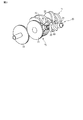
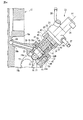
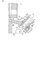
図1は、エンジンのシリンダブロック10の一部と、サプライポンプ20とを示している。サプライポンプ20は、加圧した燃料をインジェクタに供給するための燃料供給系の一部をなしている。図2は、サプライポンプ20をシリンダブロック10に組付ける前の状態を示している。図3にクランクシャフト11とサプライポンプ20などが模式的に示されている。
Claims (6)
- オイル供給流路を有するシリンダブロックのサプライポンプ取付部に形成されたアダプタ取付面と、
前記サプライポンプ取付部に形成され前記シリンダブロックの内部空間に連通しかつ前記アダプタ取付面に開口部を有したアダプタ挿入孔と、
前記開口部から前記アダプタ挿入孔の内面を臨むことができる位置に前記開口部を通る直線に沿って形成され、前記内面から前記オイル供給流路に達する給油孔と、
を具備したことを特徴とするシリンダブロックのサプライポンプ取付構造。 - 前記アダプタ挿入孔に挿入されたアダプタ部材をさらに有し、
該アダプタ部材は、前記アダプタ取付面に接する第1フランジと、サプライポンプを支持する第2フランジと、前記サプライポンプのポンプ機構部が挿入されるポンプ挿入孔と、前記給油孔に連通する給油連通孔と、を備えたことを特徴とする請求項1に記載のシリンダブロックのサプライポンプ取付構造。 - 前記ポンプ機構部はタペットを含み、
前記アダプタ部材は、前記タペットが移動する軌跡の両端を越える長さを有する空気逃がし部を備えたことを特徴とする請求項2に記載のシリンダブロックのサプライポンプ取付構造。 - 前記空気逃がし部は、前記給油孔の延長線に対して前記ポンプ挿入孔の周方向に互いに位置をずらして形成された複数の溝を含むことを特徴とする請求項3に記載のシリンダブロックのサプライポンプ取付構造。
- 前記サプライポンプ取付部が回り止め部材を挿入する回り止め取付孔を有し、前記アダプタ部材は前記回り止め取付孔と対応した位置に前記回り止め部材の先端が挿入される回り止め挿入孔を有し、前記回り止め部材の先端が前記タペットのガイド溝に挿入されたことを特徴とする請求項3または4に記載のシリンダブロックのサプライポンプ取付構造。
- エンジンのクランクシャフトの回転を前記サプライポンプのタペットに伝えるポンプ駆動系を有し、該ポンプ駆動系は、前記シリンダブロックの前記内部空間に配置され前記ポンプ機構部のカムフォロアに接するカムと、前記クランクシャフトの回転に連動して回転するクランク軸ギヤと、該クランク軸ギヤに噛合い該クランク軸ギヤの回転を前記カムに伝えるポンプ駆動ギヤとを含むことを特徴とする請求項3から5のいずれか1項に記載のシリンダブロックのサプライポンプ取付構造。
Priority Applications (1)
| Application Number | Priority Date | Filing Date | Title |
|---|---|---|---|
| JP2015255079A JP6610248B2 (ja) | 2015-12-25 | 2015-12-25 | シリンダブロックのサプライポンプ取付構造 |
Applications Claiming Priority (1)
| Application Number | Priority Date | Filing Date | Title |
|---|---|---|---|
| JP2015255079A JP6610248B2 (ja) | 2015-12-25 | 2015-12-25 | シリンダブロックのサプライポンプ取付構造 |
Publications (2)
| Publication Number | Publication Date |
|---|---|
| JP2017115825A true JP2017115825A (ja) | 2017-06-29 |
| JP6610248B2 JP6610248B2 (ja) | 2019-11-27 |
Family
ID=59233966
Family Applications (1)
| Application Number | Title | Priority Date | Filing Date |
|---|---|---|---|
| JP2015255079A Active JP6610248B2 (ja) | 2015-12-25 | 2015-12-25 | シリンダブロックのサプライポンプ取付構造 |
Country Status (1)
| Country | Link |
|---|---|
| JP (1) | JP6610248B2 (ja) |
Cited By (1)
| Publication number | Priority date | Publication date | Assignee | Title |
|---|---|---|---|---|
| WO2019151038A1 (ja) * | 2018-01-31 | 2019-08-08 | いすゞ自動車株式会社 | 潤滑油供給構造 |
-
2015
- 2015-12-25 JP JP2015255079A patent/JP6610248B2/ja active Active
Cited By (3)
| Publication number | Priority date | Publication date | Assignee | Title |
|---|---|---|---|---|
| WO2019151038A1 (ja) * | 2018-01-31 | 2019-08-08 | いすゞ自動車株式会社 | 潤滑油供給構造 |
| JP2019132210A (ja) * | 2018-01-31 | 2019-08-08 | いすゞ自動車株式会社 | 潤滑油供給構造 |
| JP7049596B2 (ja) | 2018-01-31 | 2022-04-07 | いすゞ自動車株式会社 | 潤滑油供給構造 |
Also Published As
| Publication number | Publication date |
|---|---|
| JP6610248B2 (ja) | 2019-11-27 |
Similar Documents
| Publication | Publication Date | Title |
|---|---|---|
| US20080175731A1 (en) | Transfer pump for injection of fuel at high pressure | |
| CN101265833B (zh) | 带阀的冷却喷雾器 | |
| US20110100319A1 (en) | Lubrication system for fuel pump of gdi engine | |
| CN104612958A (zh) | 泵 | |
| CN107110092B (zh) | 用于将燃料、优选柴油供送至内燃机的泵单元 | |
| JP2015505011A (ja) | 燃料ポンプ用のポンプヘッド | |
| US7950373B2 (en) | Check valve with separate spherical spring guide | |
| US8272856B2 (en) | High-pressure pump, in particular for a fuel injection apparatus of an internal combustion engine | |
| JP6610248B2 (ja) | シリンダブロックのサプライポンプ取付構造 | |
| CA2889356C (en) | Chain saw and fluid pump | |
| EP2088309A1 (en) | High-pressure fuel feed pump | |
| EP3085944B1 (en) | Externally sprung tappet with head turret guide for a fuel pump | |
| KR100475987B1 (ko) | 고압연료 공급장치 | |
| WO2017094438A1 (ja) | リリーフ弁装置、及び、それを用いる高圧ポンプ | |
| ATE417200T1 (de) | Hochdruckpumpe für eine kraftstoffeinspritzeinrichtung einer brennkraftmaschine | |
| JP2013194616A (ja) | 高圧燃料供給ポンプ | |
| CN110121593B (zh) | 用于将燃料、优选柴油供应到内燃机的泵总成 | |
| JP6570309B2 (ja) | 燃料供給ポンプ | |
| JP6239094B2 (ja) | 燃料噴射ポンプ | |
| JP2005188379A (ja) | 逆止弁及びその逆止弁を備える燃料噴射ポンプ | |
| GB2601950A (en) | Lifter providing improved cam lobe lubrication | |
| JP2015214974A (ja) | 流体バルブアセンブリ | |
| JP2016014373A (ja) | 内燃機関のオイルジェット装置 | |
| JP5840865B2 (ja) | 燃料ポンプ | |
| KR200231065Y1 (ko) | 오일제트의 체크밸브 |
Legal Events
| Date | Code | Title | Description |
|---|---|---|---|
| A621 | Written request for application examination |
Free format text: JAPANESE INTERMEDIATE CODE: A621 Effective date: 20181130 |
|
| TRDD | Decision of grant or rejection written | ||
| A977 | Report on retrieval |
Free format text: JAPANESE INTERMEDIATE CODE: A971007 Effective date: 20190925 |
|
| A01 | Written decision to grant a patent or to grant a registration (utility model) |
Free format text: JAPANESE INTERMEDIATE CODE: A01 Effective date: 20191001 |
|
| A61 | First payment of annual fees (during grant procedure) |
Free format text: JAPANESE INTERMEDIATE CODE: A61 Effective date: 20191014 |
|
| R150 | Certificate of patent or registration of utility model |
Ref document number: 6610248 Country of ref document: JP Free format text: JAPANESE INTERMEDIATE CODE: R150 |