JP2017117607A - Cooker - Google Patents
Cooker Download PDFInfo
- Publication number
- JP2017117607A JP2017117607A JP2015250910A JP2015250910A JP2017117607A JP 2017117607 A JP2017117607 A JP 2017117607A JP 2015250910 A JP2015250910 A JP 2015250910A JP 2015250910 A JP2015250910 A JP 2015250910A JP 2017117607 A JP2017117607 A JP 2017117607A
- Authority
- JP
- Japan
- Prior art keywords
- body case
- main body
- cover
- cooking
- insertion port
- Prior art date
- Legal status (The legal status is an assumption and is not a legal conclusion. Google has not performed a legal analysis and makes no representation as to the accuracy of the status listed.)
- Granted
Links
Images









Landscapes
- Combinations Of Kitchen Furniture (AREA)
- Induction Heating Cooking Devices (AREA)
- Baking, Grill, Roasting (AREA)
Abstract
【課題】 厨房家具の中に設置される加熱調理器において、大きな付属品やその他物品も収容できる収納室を用意し、かつその収納室の前面開口を開閉自在に覆うカバーを設けることによって、厨房家具の前面と垂直方向における平面度を調和させる加熱調理器を提供する。【解決手段】トッププレートの上に置かれ、被調理物を収容する金属製の調理器具を加熱手段によって加熱する加熱調理器であって、厨房家具の中に設置される箱状の本体ケース又は下部ユニットに、前方に挿入口を有した収納室を区画形成し、この収納室の挿入口から、調理に使用する調理器具やその他付属品を取り出し可能に挿入する構成とし、さらに調理器具を格納中の収納室の挿入口を開閉自在に覆うカバーを備え、そのカバーの位置が、カバーの左側又は右側の少なくとも何れか一方に隣接する厨房家具の前面構成材の前面と合致する位置に設定されている。【選択図】図1PROBLEM TO BE SOLVED: To prepare a storage room for storing large accessories and other articles in a heating cooker installed in kitchen furniture, and to provide a cover for opening and closing the front opening of the storage room. Provided is a heating cooker that harmonizes the flatness in the vertical direction with the front surface of furniture. A heating cooker which is placed on a top plate and heats a metal cooking utensil containing a food to be cooked by heating means, and is a box-shaped main body case installed in kitchen furniture or A storage room with an insertion slot in the front is defined in the lower unit, and cooking utensils and other accessories used for cooking are removably inserted from the insertion slot of the storage room, and the cooking utensils are stored. A cover that covers the insertion opening of the inner storage room so as to be openable and closable, and the position of the cover is set to a position that matches the front of the front component of the kitchen furniture adjacent to at least one of the left side or the right side of the cover ing. [Selection] Figure 1
Description
本発明は、例えば、トッププレートの上に置かれた鍋等の金属製調理容器を誘導加熱する加熱コイルを備えた誘導加熱調理器や、鍋等を下方から加熱するガスバーナーを備えた加熱調理器であって、流し台等の厨房家具(「キッチンカウンター」ともいう)に組み込まれた型式の加熱調理器に関するものである。 The present invention is, for example, an induction heating cooker provided with a heating coil for induction heating a metal cooking container such as a pan placed on a top plate, or cooking with a gas burner for heating a pan or the like from below. The present invention relates to a heating cooker of a type incorporated in kitchen furniture such as a sink (also called “kitchen counter”).
従来の加熱調理器として、本体の内部左側にグリル庫を具備したものがある。そのグリルは、前面に設けられた扉を開けてから、グリル庫内に魚等の被加熱物を挿入し、扉を閉めて加熱調理が可能になっている(例えば、特許文献1参照)。 As a conventional cooking device, there is one having a grill box on the left side inside the main body. In the grill, after opening a door provided on the front surface, a heated object such as a fish is inserted into the grill cabinet, and the door is closed to allow cooking by heating (see, for example, Patent Document 1).
また、厨房家具に組み込まれて使用される加熱調理器の本体の内部が、グリル庫と、その左右にある収納室とに区画されているタイプの加熱調理器が存在する。その収納室には、食材、調味料や調理容器などが収納されるようになっている(例えば、特許文献2参照)。
この収納室は、加熱調理器の運転によって、厨房家具(キッチンカウンター)の内部空間が高温度にならないように、厨房家具の外部から吸い込まれる空気を取り入れる空気取り込み口を備えたカバーによって前面が覆われ、運転中は収納室に空気が取り入れられるようになっている。
In addition, there is a type of heating cooker in which the inside of the main body of the heating cooker used by being incorporated in kitchen furniture is divided into a grill cabinet and storage chambers on the left and right. In the storage room, ingredients, seasonings, cooking containers, and the like are stored (see, for example, Patent Document 2).
The front of this storage room is covered by a cover with an air intake port that takes in air that is sucked in from outside the kitchen furniture so that the interior space of the kitchen furniture (kitchen counter) does not become hot due to the operation of the cooking device. During operation, air can be taken into the storage room.
前述した代表的な2つのタイプの従来の加熱調理器では、何れもグリル庫を具備することが前提に構成されているため、加熱調理器全体のコストが高くなることは避けられない。また、グリル庫は、加熱調理器の本体内部に内蔵されているため、グリル庫内全体を清掃することも容易ではない等の課題が従来から指摘されていた。さらに、グリル庫で魚を焼いたあとには、そのグリル庫に魚の臭いが残存するため、グリル庫で別の調理(例えばケーキを焼くこと)をするのを避ける傾向もあり、グリル庫が有効活用されているとは言えない現状があった。 The above-described two typical types of conventional cooking devices are configured on the premise that they are equipped with a grill cabinet, and therefore the cost of the entire cooking device is inevitable. In addition, since the grill cabinet is built in the main body of the heating cooker, problems such as the fact that it is not easy to clean the entire grill cabinet have been pointed out. In addition, after the fish is baked in the grill, the smell of the fish remains in the grill, so there is a tendency to avoid cooking another food in the grill (for example, baking a cake). There was a current situation that cannot be said to be utilized.
本発明は、前述のような課題を解決するためになされたもので、加熱調理器本体にはグリル庫を内蔵せず、そのグリル庫の空間を有効に利用した加熱調理器を提供することを目的とする。 The present invention has been made to solve the above-described problems, and provides a cooking device that does not incorporate a grill in the cooking device body, and effectively uses the space of the grill. Objective.
第1の発明になる本発明に係る加熱調理器は、厨房家具に組み込まれて使用されるものであって、上部にトッププレートが設けられ、前記厨房家具に支持される本体ケースと、この本体ケースの前面に形成された挿入口から後方側に連続して当該本体ケースの内部に設けられた収納室と、本体ケース内部に配置された電気エネルギーによる加熱手段と、前記挿入口の前方側を開閉自在に塞ぐように前記本体ケースに取り付けられるカバーと、を備え、前記加熱手段は、前記トッププレートの上方に置かれた状態の被調理物を収容する金属製の調理器具を加熱でき、前記収納室は、前記挿入口から挿入される物品を、取り出し可能に格納できる大きさを有し、前記カバーは、前記挿入口を閉じた状態で、その左側又は右側の少なくとも何れか一方に隣接する前記厨房家具の前面と合わせた位置に設置されるものである。
この第1の発明になる加熱調理器によれば、本体ケースの内部には、収納室が確保されており、この中に挿入口から付属品や調理器具等の物品を挿入して格納でき、また必要な都度取り出すことができる。しかも、厨房家具に組み込まれた状態では、前記収納室の前方を覆うカバーが、その左側又は右側の少なくとも何れか一方に隣接する厨房家具の前面と大きな段差を生ずることがない。
A cooking device according to the present invention according to a first aspect of the present invention is used by being incorporated in kitchen furniture, and a main body case provided with a top plate on the top and supported by the kitchen furniture, and the main body A storage chamber provided inside the main body case continuously from the insertion port formed on the front surface of the case to the rear side, a heating means by electric energy arranged inside the main body case, and a front side of the insertion port. A cover attached to the main body case so as to be freely opened and closed, and the heating means can heat a metal cooking utensil that accommodates an object to be cooked placed above the top plate, The storage chamber has a size capable of removably storing an article inserted from the insertion port, and the cover has at least one of the left side and the right side in a state where the insertion port is closed. It is disposed to the front and the combined position of the kitchen furniture adjacent.
According to the cooking device according to the first aspect of the present invention, a storage room is secured inside the main body case, and articles such as accessories and cooking utensils can be inserted and stored therein from the insertion port, It can be taken out whenever necessary. Moreover, in the state of being incorporated in the kitchen furniture, the cover covering the front of the storage room does not cause a large step from the front surface of the kitchen furniture adjacent to at least one of the left side or the right side.
第2の発明になる本発明に係る加熱調理器は、厨房家具に組み込まれて使用されるものであって、上部にトッププレートが設けられ、前記厨房家具に支持される本体ケースと、この本体ケースの前面に形成された挿入口から後方側に連続して当該本体ケースの内部に設けられた収納室と、前記トッププレートの下方に配置された誘導加熱コイルと、前記本体ケースの内部に収納され前記誘導加熱コイルに高周波電力を供給するインバーター回路と、を備え、前記誘導加熱コイルは、前記トッププレートの上方に置かれた状態の被調理物を収容する金属製の調理器具を加熱でき、前記本体ケースの前面には、前記挿入口を開閉自在に塞ぐためのカバーと、このカバーと隣接するように前記本体ケースの前面に取り付けられた飾り板と、を備え、前記収納室は、前記調理器具を前記挿入口から挿入して格納できる大きさを有し、前記カバーは、前記挿入口を閉じた状態で、その左側又は右側の少なくとも何れか一方に隣接する前記飾り板の前面位置と合され、当該飾り板はそれと隣接する厨房家具の前面と合わせた位置に設置されるものである。
この第2の発明になる加熱調理器によれば、本体ケースの内部に設けられた収納室に、その前方の挿入口から金属製の調理器具を挿入して格納できる。しかも、厨房家具に組み込まれた状態では、加熱調理器の前面を覆うカバーと飾り板の双方が、その左側又は右側の少なくとも何れか一方に隣接する厨房家具の前面と大きな段差を生ずることがないので、加熱調理器前面と厨房家具の前面との全体に、統一的平面感を持たせることができる。
A cooking device according to the present invention according to a second aspect of the present invention is used by being incorporated in kitchen furniture, and a main body case provided with a top plate on the top and supported by the kitchen furniture, and the main body A storage chamber provided inside the main body case continuously from the insertion port formed on the front surface of the case to the rear side, an induction heating coil disposed below the top plate, and stored in the main body case And an inverter circuit for supplying high-frequency power to the induction heating coil, and the induction heating coil can heat a metal cooking utensil that accommodates an object to be cooked placed above the top plate, A front surface of the main body case includes a cover for opening and closing the insertion opening, and a decorative plate attached to the front surface of the main body case so as to be adjacent to the cover. The storage chamber has a size that allows the cooking utensil to be inserted and stored through the insertion port, and the cover is adjacent to at least one of the left side or the right side thereof with the insertion port closed. The decorative plate is aligned with the front surface position of the decorative plate, and the decorative plate is installed at a position combined with the front surface of the kitchen furniture adjacent thereto.
According to the heating cooker which becomes this 2nd invention, a metal cooking utensil can be inserted and stored in the storage room provided in the inside of the main body case from the front insertion port. Moreover, in the state of being incorporated in the kitchen furniture, both the cover and the decorative plate covering the front surface of the heating cooker do not cause a large step from the front surface of the kitchen furniture adjacent to at least one of the left side or the right side thereof. Therefore, a uniform flat feeling can be given to the entire front surface of the cooking device and the front surface of the kitchen furniture.
第3の発明になる本発明に係る加熱調理器は、厨房家具に組み込まれて使用されるものであって、上部にトッププレートが設けられ、前記厨房家具に支持される本体ケースと、この本体ケースの前面に形成された挿入口から後方側に連続して当該本体ケースの内部に設けられた収納室と、本体ケース内部に配置された電気エネルギーによる加熱手段と、前記挿入口の前方側を開閉自在に塞ぐように前記本体ケースに取り付けられるカバーと、このカバーと連結されており、カバーの前後方向の移動に伴って前記収納室内を前後方向に移動するトレイと、を備え、前記加熱手段は、前記トッププレートの上方に置かれた状態の被調理物を収容する金属製の調理器具を加熱でき、前記収納室は、前記調理器具が前記挿入口から挿入されて前記トレイの上に格納できる大きさを有し、前記カバーは、前記挿入口を閉じた状態で、その左側又は右側の少なくとも何れか一方に隣接する前記厨房家具の前面と合わせた位置に設置され、前記カバーを前方に移動させて前記挿入口を開けた状態で、前記トレイに載せられた前記調理器具が、当該挿入口から外部に露出するものである。
この第3の発明になる加熱調理器によれば、本体ケースの内部に設けられた収納室に、その前方の挿入口から金属製の調理器具を挿入して格納できる。しかも、厨房家具に組み込まれた状態では、加熱調理器の前面を覆うカバーが、その左側又は右側の少なくとも何れか一方に隣接する厨房家具の前面と大きな段差を生ずることがない。さらに、カバーと一体化されているトレイによって調理器具を前方へ引き出すことができ、使用者の操作性を向上させることができる。
A cooking device according to the present invention according to a third aspect of the present invention is used by being incorporated in kitchen furniture, and a main body case provided with a top plate at the top and supported by the kitchen furniture, and the main body A storage chamber provided inside the main body case continuously from the insertion port formed on the front surface of the case to the rear side, a heating means by electric energy arranged inside the main body case, and a front side of the insertion port. A cover that is attached to the main body case so as to be freely opened and closed, and a tray that is connected to the cover and moves in the front-rear direction as the cover moves in the front-rear direction; Is capable of heating a metal cooking utensil that accommodates an object to be cooked placed above the top plate, and the storage chamber is configured such that the cooking utensil is inserted from the insertion port and the tray is inserted. The cover is installed at a position combined with the front surface of the kitchen furniture adjacent to at least one of the left side or the right side thereof with the insertion port closed. In a state where the cover is moved forward and the insertion opening is opened, the cooking utensil placed on the tray is exposed to the outside from the insertion opening.
According to the heating cooker which becomes this 3rd invention, a metal cooking utensil can be inserted and stored in the storage room provided in the inside of the main body case from the front insertion port. And in the state integrated in the kitchen furniture, the cover which covers the front surface of a heating cooker does not produce a big level | step difference with the front surface of the kitchen furniture adjacent to either the left side or the right side. Furthermore, the cooking utensil can be pulled forward by the tray integrated with the cover, and the operability for the user can be improved.
第4の発明になる本発明に係る加熱調理器は、厨房家具に組み込まれて使用されるものであって、上部に調理器具を支えるためのトッププレートが設けられ、前面に前記調理器具の挿入口となる開口部を有し、前記厨房家具に支持される本体ケースと、前記挿入口に連続して前記本体ケースの内部に設けられた前記調理器具が収納可能な収納室と、前記挿入口の前方側を開閉自在に塞ぐように前記本体ケースに取り付けられるカバーと、前記トッププレートの下方に配置された誘導加熱コイルと、前記本体ケースの内部に収納され前記誘導加熱コイルに高周波電力を供給するインバーター回路と、前記インバーター回路の動作を制御する制御装置と、を備え、前記カバーは、前記挿入口を閉じた状態で、その左側又は右側の少なくとも何れか一方に隣接する前記厨房家具の前面と合わせた位置に設置されるものであり、前記制御装置には、前記カバーが開いている状態を検知し、当該カバーが開いている状態では前記インバーター回路の動作開始を禁止する安全装置を設けているものである。
この第4の発明になる加熱調理器によれば、本体ケースの内部に設けられた収納室に、その前方の挿入口から金属製の調理器具を挿入して格納できる。しかも、厨房家具に組み込まれた状態では、加熱調理器の前面を覆うカバーが、その左側又は右側の少なくとも何れか一方に隣接する厨房家具の前面と大きな段差を生ずることがない。さらに、前記カバーが開いている状態では前記インバーター回路の動作開始が自動的に禁止されるので、安全性を高めることができる。
A cooking device according to the present invention according to a fourth aspect of the present invention is used by being incorporated in kitchen furniture, provided with a top plate for supporting the cooking utensil on the top, and inserting the cooking utensil on the front surface. A main body case supported by the kitchen furniture, a storage chamber provided inside the main body case, which can be stored in the main body case, and the insertion port; A cover attached to the main body case so as to freely open and close the front side, an induction heating coil disposed below the top plate, and a high frequency power supplied to the induction heating coil housed in the main body case An inverter circuit that controls the operation of the inverter circuit, and the cover has at least one of the left side and the right side thereof with the insertion port closed. It is installed at a position combined with the front surface of the kitchen furniture adjacent to the side, and the control device detects a state where the cover is open, and in the state where the cover is open, the inverter circuit A safety device that prohibits the start of operation is provided.
According to the heating cooker which becomes this 4th invention, a metal cooking utensil can be inserted and stored in the storage room provided in the inside of the main body case from the insertion port of the front. And in the state integrated in the kitchen furniture, the cover which covers the front surface of a heating cooker does not produce a big level | step difference with the front surface of the kitchen furniture adjacent to either the left side or the right side. Further, since the start of the operation of the inverter circuit is automatically prohibited when the cover is open, safety can be improved.
第5の発明になる本発明に係る加熱調理器は、厨房家具に組み込まれて使用されるものであって、上部に調理器具を支えるためのトッププレートが設けられ、前面に前記調理器具の挿入口となる開口部を有し、前記厨房家具に支持される本体ケースと、前記挿入口に連続して前記本体ケースの内部に設けられた前記調理器具が収納可能な収納室と、前記挿入口の前方側を開閉自在に塞ぐように前記本体ケースに取り付けられるカバーと、前記トッププレートの下方に配置された誘導加熱コイルと、前記本体ケースの内部に収納され前記誘導加熱コイルに高周波電力を供給するインバーター回路と、前記インバーター回路の動作を制御する制御装置と、前記誘導加熱コイルを冷却するための空気を前記本体ケースの外部から取り込む送風機と、を備え、前記収納室は、前記挿入口を除いた左右側方と上下面、及び後方側が一連の壁面材で囲まれ、前記送風機の冷却風が流れない閉鎖空間として区画され、前記本体ケースの内部には、前記閉鎖空間の外側にある冷却用空間に、前記誘導加熱コイル、インバーター回路及び前記送風機が配置され、前記冷却用空間に通ずる外気の導入口と外部に通じる排気口を前記本体ケースに形成し、前記カバーは、前記挿入口を閉じた状態で、その左側又は右側の少なくとも何れか一方に隣接する前記厨房家具の前面と合わせた位置に設置されるものである。
この第5の発明になる加熱調理器によれば、本体ケースの内部に設けられた収納室に、その前方の挿入口から金属製の調理器具を挿入して格納できる。しかも、厨房家具に組み込まれた状態では、加熱調理器の前面を覆うカバーが、その左側又は右側の少なくとも何れか一方に隣接する厨房家具の前面と大きな段差を生ずることがない。さらに、前記本体ケースの内部には、前記収納室と区画された冷却用空間が形成され、この冷却用空間に存在する誘導加熱コイル、インバーター回路が、前記送風機で導入された空気によって冷却されるので、加熱調理運転中に温度が上昇する誘導加熱コイルと、インバーター回路を構成する電力制御素子等の重要な電気・電子部品の過熱を防止できる。
A cooking device according to the present invention according to a fifth aspect of the present invention is used by being incorporated in kitchen furniture, and is provided with a top plate for supporting the cooking utensil on the top, and the cooking utensil is inserted on the front surface. A main body case supported by the kitchen furniture, a storage chamber provided inside the main body case, which can be stored in the main body case, and the insertion port; A cover attached to the main body case so as to freely open and close the front side, an induction heating coil disposed below the top plate, and a high frequency power supplied to the induction heating coil housed in the main body case An inverter circuit, a control device that controls the operation of the inverter circuit, a blower that takes in air for cooling the induction heating coil from the outside of the main body case, The storage chamber is defined as a closed space in which left and right sides and upper and lower surfaces excluding the insertion port, and a rear side are surrounded by a series of wall materials and the cooling air of the blower does not flow, and the interior of the main body case In the cooling space outside the closed space, the induction heating coil, the inverter circuit, and the blower are arranged, and an external air inlet port that leads to the cooling space and an exhaust port that leads to the outside are provided in the main body case. The cover is installed at a position aligned with the front surface of the kitchen furniture adjacent to at least one of the left side and the right side thereof with the insertion port closed.
According to the heating cooker which becomes this 5th invention, a metal cooking utensil can be inserted and stored in the storage chamber provided in the inside of the main body case from the front insertion port. And in the state integrated in the kitchen furniture, the cover which covers the front surface of a heating cooker does not produce a big level | step difference with the front surface of the kitchen furniture adjacent to either the left side or the right side. Further, a cooling space partitioned from the storage chamber is formed inside the main body case, and the induction heating coil and the inverter circuit existing in the cooling space are cooled by the air introduced by the blower. Therefore, it is possible to prevent overheating of important electrical / electronic components such as the induction heating coil whose temperature rises during the cooking operation and the power control element constituting the inverter circuit.
第6の発明になる本発明に係る加熱調理器は、厨房家具に組み込まれて使用されるものであって、上部に調理器具を支えるためのトッププレートが設けられ、前面に前記調理器具の挿入口となる開口部を有し、前記厨房家具に支持される本体ケースと、前記挿入口に連続して前記本体ケースの右側又は左側寄り内部に前後方向に細長く設けられ、前記調理器具が収納可能な収納室と、前記挿入口の前方側を開閉自在に塞ぐように前記本体ケースに取り付けられるカバーと、前記トッププレートの下方に配置された誘導加熱コイルと、前記本体ケースの内部に収納され前記誘導加熱コイルに高周波電力を供給するインバーター回路と、前記インバーター回路の動作を制御する制御装置と、前記誘導加熱コイルを冷却するための空気を前記本体ケースの外部から取り込む送風機と、を備え、前記調理器具は、短径寸法SSと長径寸法LSを有し平面形状が楕円形又は長方形状であり、前記挿入口の間口は、前記短径寸法SSよりも幅広に形成され、前記カバーは、前記挿入口を閉じた状態で、その左側又は右側の少なくとも何れか一方に隣接する前記厨房家具の前面と合わせた位置に設置されるものである。
この第6の発明になる加熱調理器によれば、本体ケースの内部に設けられた収納室に、その前方の挿入口から金属製の調理器具を挿入して格納できる。しかも、厨房家具に組み込まれた状態では、加熱調理器の前面を覆うカバーが、その左側又は右側の少なくとも何れか一方に隣接する厨房家具の前面と大きな段差を生ずることがない。さらに、前記収納室は、前記本体ケースの内部の右側又は左側寄りに前後方向に細長く設けられ、この収納室の内部空間形状に合わせて前記調理器具は楕円形又は長方形状であるため、調理器具で秋刀魚等の細長い被調理物も調理でき、しかも収納室が左右どちらかの方向に位置しているため、本体ケースの内部に格納すべき、誘導加熱コイル、インバーター回路、制御装置及び送風機を臨ませた、一連の設置空間を確保できる。
A cooking device according to the present invention according to a sixth aspect of the present invention is used by being incorporated in kitchen furniture, and is provided with a top plate for supporting the cooking utensil on the top, and the cooking utensil is inserted on the front surface. A main body case supported by the kitchen furniture having an opening serving as a mouth, and elongated in the front-rear direction inside the right or left side of the main body case continuously to the insertion opening, and can store the cooking utensil A storage chamber, a cover attached to the main body case so as to freely open and close the front side of the insertion port, an induction heating coil disposed below the top plate, and stored in the main body case An inverter circuit for supplying high-frequency power to the induction heating coil, a control device for controlling the operation of the inverter circuit, and air for cooling the induction heating coil are supplied to the main body casing. The cooking appliance has a short diameter dimension SS and a long diameter dimension LS and has a planar shape of an ellipse or a rectangle, and the front end of the insertion opening has the short diameter dimension SS. The cover is installed at a position combined with the front surface of the kitchen furniture adjacent to at least one of the left side or the right side thereof with the insertion port closed.
According to the cooking device according to the sixth aspect of the present invention, the metal cooking utensil can be inserted and stored in the storage chamber provided inside the main body case from the insertion port in front of the storage chamber. And in the state integrated in the kitchen furniture, the cover which covers the front surface of a heating cooker does not produce a big level | step difference with the front surface of the kitchen furniture adjacent to either the left side or the right side. Furthermore, the storage chamber is provided in a long and narrow direction in the front-rear direction on the right side or the left side of the inside of the main body case, and the cooking utensil has an oval or rectangular shape according to the internal space shape of the storage chamber. Because it can cook slender fish such as sword fish and the storage room is located in either the left or right direction, the induction heating coil, inverter circuit, control device and blower that should be stored inside the main body case are exposed. A series of installation spaces can be secured.
第7の発明になる本発明に係る加熱調理器は、厨房家具に組み込まれて使用されるものであって、上部に調理器具を支えるためのトッププレートが設けられ、前面に前記調理器具の挿入口となる開口部を有し、前記厨房家具に支持される本体ケースと、前記挿入口に連続して前記本体ケースの内部に設けられ前記調理器具が収納可能な収納室と、前記挿入口の前方側を開閉自在に塞ぐように前記本体ケースに取り付けられるカバーと、前記トッププレートの下方に配置された誘導加熱コイルと、前記本体ケースの内部に収納され前記誘導加熱コイルに高周波電力を供給するインバーター回路と、前記インバーター回路の動作を制御する制御装置と、前記制御装置に使用者が入力信号を与えることができる操作部と、外部から前記制御装置の制御に関する情報を取得する無線通信部と、を備え、前記カバーは、前記挿入口を閉じた状態で、その左側又は右側の少なくとも何れか一方に隣接する厨房家具の前面と合わせた位置に設置されているものであり、前記操作部には、前記調理器具を使用する場合に、前記無線通信部を介して調理参考情報を取得することを指令する指令スイッチを備えているものである。
この第7の発明になる加熱調理器によれば、本体ケースの内部に設けられた収納室に、その前方の挿入口から金属製の調理器具を挿入して格納できる。しかも、厨房家具に組み込まれた状態では、加熱調理器の前面を覆うカバーが、その左側又は右側の少なくとも何れか一方に隣接する厨房家具の前面と大きな段差を生ずることがない。さらに、前記調理器具を収納室から取り出して使用する際に、調理に参考となる情報を外部から無線通信で取得することができるので、特定の調理器具を使う場合の利便性を高めることができる。
A cooking device according to the present invention according to a seventh aspect of the present invention is used by being incorporated in kitchen furniture, and is provided with a top plate for supporting the cooking utensil on the top, and the cooking utensil is inserted on the front surface. A main body case supported by the kitchen furniture, a storage room provided inside the main body case, which can be accommodated in the main body case, and capable of storing the cooking utensil; A cover attached to the main body case so as to freely open and close the front side, an induction heating coil arranged below the top plate, and a high frequency power supplied to the induction heating coil housed in the main body case An inverter circuit, a control device that controls the operation of the inverter circuit, an operation unit that allows a user to give an input signal to the control device, and an external control of the control device. A wireless communication unit that obtains information on, wherein the cover is installed at a position that is aligned with the front of the kitchen furniture adjacent to at least one of the left side or the right side thereof with the insertion port closed. The operation unit is provided with a command switch for instructing to acquire cooking reference information via the wireless communication unit when the cooking utensil is used.
According to the cooking device according to the seventh aspect of the present invention, a metal cooking utensil can be inserted into the storage chamber provided inside the main body case from the front insertion port and stored. And in the state integrated in the kitchen furniture, the cover which covers the front surface of a heating cooker does not produce a big level | step difference with the front surface of the kitchen furniture adjacent to either the left side or the right side. Furthermore, when the cooking utensil is taken out from the storage room and used, information useful for cooking can be acquired from outside by wireless communication, so that the convenience when using a specific cooking utensil can be improved. .
第8の発明になる本発明に係る加熱調理器は、厨房家具に組み込まれて使用されるものであって、上部にトッププレートが設けられ、前記厨房家具に支持される上部本体ケースと、この上部本体ケースと連結された下部本体ケースと、前面に形成された挿入口から後方側に連続して前記下部本体ケースの内部に設けられた収納室と、前記上部ケース内部に配置された電気エネルギーによる加熱手段と、前記挿入口の前方側を開閉自在に塞ぐように前記下部本体ケースに取り付けられるカバーと、を備え、前記加熱手段は、前記トッププレートの上方に置かれた状態の被調理物を収容する金属製の調理器具を加熱でき、前記収納室は、前記調理器具を前記挿入口から挿入して格納できる大きさを有し、前記カバーは、前記挿入口を閉じた状態で、その左側又は右側の少なくとも何れか一方に隣接する前記厨房家具の前面と合わせた位置に設置されるものである。
この第8の発明になる加熱調理器によれば、上部本体ケースと別に形成され、上部本体ケースに結合される下部本体ケースの内部の収納室に、その前方の挿入口から金属製の調理器具を挿入して格納できる。しかも、厨房家具に組み込まれた状態では、加熱調理器の前面を覆うカバーが、その左側又は右側の少なくとも何れか一方に隣接する厨房家具の前面と大きな段差を生ずることがない。
A cooking device according to the present invention according to an eighth aspect of the present invention is used by being incorporated in kitchen furniture, and is provided with a top plate provided on the upper portion and supported by the kitchen furniture, A lower main body case connected to the upper main body case, a storage chamber provided inside the lower main body case continuously from the insertion port formed on the front surface to the rear side, and electric energy disposed in the upper case Heating means, and a cover attached to the lower body case so as to freely open and close the front side of the insertion opening, the heating means being cooked in a state of being placed above the top plate The storage chamber has a size that allows the cooking utensil to be inserted and stored through the insertion port, and the cover closes the insertion port. It is disposed to the front and the combined position of the kitchen furniture adjacent to at least one of the left or right.
According to the cooking device according to the eighth aspect of the present invention, a metal cooking utensil is formed in the storage chamber inside the lower main body case formed separately from the upper main body case and coupled to the upper main body case from the front insertion port. Can be inserted and stored. And in the state integrated in the kitchen furniture, the cover which covers the front surface of a heating cooker does not produce a big level | step difference with the front surface of the kitchen furniture adjacent to either the left side or the right side.
第9の発明になる本発明に係る加熱調理器は、厨房家具に組み込まれて使用されるものであって、上部にトッププレートが設けられ、前記厨房家具に支持される本体ケースと、この本体ケースの前面に形成された挿入口から後方側に連続して当該本体ケースの内部に設けられた収納室と、前記トッププレートより上方に配置された五徳と、当該五徳の上に置かれて使用され、かつ被調理物を収容するための金属製の調理器具を、ガス燃焼エネルギーによって加熱する加熱手段と、前記挿入口の前方側を開閉自在に塞ぐように前記本体ケースに取り付けられるカバーと、を備え、前記収納室は、前記調理器具を前記挿入口から挿入して格納できる大きさを有し、前記カバーは、前記挿入口を閉じた状態で、その左側又は右側の少なくとも何れか一方に隣接する前記厨房家具の前面と合わせた位置に設置されるものである。
この第9の発明になる加熱調理器によれば、本体ケースの内部に設けられた収納室に、その前方の挿入口から金属製の調理器具を挿入して格納できる。しかも、厨房家具に組み込まれた状態では、加熱調理器の前面を覆うカバーが、その左側又は右側の少なくとも何れか一方に隣接する厨房家具の前面と大きな段差を生ずることがない。
A cooking device according to the present invention according to a ninth aspect of the present invention is used by being incorporated in kitchen furniture, and a main body case provided with a top plate at the top and supported by the kitchen furniture, and the main body A storage chamber provided inside the main body case continuously from the insertion port formed on the front surface of the case to the rear side, five virtues arranged above the top plate, and placed on the five virtues And a heating means for heating a metal cooking utensil for containing the object to be cooked by gas combustion energy, and a cover attached to the main body case so as to openably close the front side of the insertion port, The storage chamber has a size that allows the cooking utensil to be inserted and stored through the insertion port, and the cover has at least one of the left side and the right side in a state where the insertion port is closed. It is disposed to the front and the combined position of the kitchen furniture next to one.
According to the cooking device according to the ninth aspect of the present invention, the metal cooking utensil can be inserted and stored in the storage chamber provided inside the main body case from the insertion port in front of the storage chamber. And in the state integrated in the kitchen furniture, the cover which covers the front surface of a heating cooker does not produce a big level | step difference with the front surface of the kitchen furniture adjacent to either the left side or the right side.
第10の発明に係る加熱調理器は、厨房家具に組み込まれて使用されるものであって、上部にトッププレートが設けられ、前記厨房家具に支持される本体ケースと、この本体ケースの前面に形成された挿入口から後方側に連続して当該本体ケースの内部に設けられた収納室と、前記トッププレートの下方に配置された誘導加熱コイルと、前記本体ケースの内部に収納され前記誘導加熱コイルに高周波電力を供給するインバーター回路と、底面の形状が長方形又は楕円形の金属製調理器具が置かれたことを検知し、前記誘導加熱コイルに対する電力供給を制御する制御装置と、を備え、
前記誘導加熱コイルは、平面形状が円形の中心コイルと、この中心コイルの周囲にあって、当該中心コイルとは独立して電力が供給される、1つ又は複数個の副加熱コイルとから構成されており、
前記中心コイルと、副加熱コイルの両方の上方に及ぶように前記調理器具が置かれて誘導加熱調理を行う場合、前記制御装置は前記中心コイルと当該副加熱コイルの双方に電力を供給する制御を行い、
前記本体ケースの前面には、前記挿入口を開閉自在に塞ぐためのカバーを備え、前記収納室は、前記調理器具を前記挿入口から挿入して格納できる大きさを有し、前記カバーは、前記挿入口を閉じた状態で、その左側又は右側の少なくとも何れか一方に隣接する前記厨房家具の前面と合わせた位置に設置されるものである。
この第10の発明になる加熱調理器によれば、本体ケースの内部に設けられた収納室に、その前方の挿入口から金属製の調理器具を挿入して格納できる。しかも、厨房家具に組み込まれた状態では、加熱調理器の前面を覆うカバーが、その左側又は右側の少なくとも何れか一方に隣接する厨房家具の前面と大きな段差を生ずることがないので、加熱調理器前面と厨房家具の前面との全体に、統一的平面感を持たせることができる。
さらに、前記誘導加熱コイルは、中心コイルと独立して電力が供給される副加熱コイルを備えており、その副加熱コイルと中心コイルの協同加熱時には、加熱できる範囲が大きくなるので、円形以外の直径の大きな調理器具であっても誘導加熱でき、しかもそのような調理器具を、使用しない場合には、前記収納室に格納できるから、使用時、非使用時の双方で利便性を高めることができる。
A cooking device according to a tenth aspect of the present invention is used by being incorporated in kitchen furniture, and a top plate is provided on the top, and is supported by the kitchen furniture, and on the front surface of the main body case. A storage chamber provided inside the main body case continuously from the formed insertion port to the rear side, an induction heating coil disposed below the top plate, and the induction heating housed in the main body case An inverter circuit that supplies high-frequency power to the coil, and a control device that detects that a metal cookware having a rectangular or oval bottom is placed and controls the power supply to the induction heating coil,
The induction heating coil includes a central coil having a circular planar shape, and one or a plurality of sub-heating coils around the central coil and supplied with power independently of the central coil. Has been
When the cooking utensil is placed so as to extend above both the center coil and the sub-heating coil and the induction heating cooking is performed, the control device controls to supply power to both the center coil and the sub-heating coil. And
A front surface of the main body case is provided with a cover for closing the insertion port so that the opening can be opened and closed, and the storage chamber has a size that allows the cooking utensil to be inserted and stored from the insertion port. In a state where the insertion port is closed, the insertion port is installed at a position combined with the front surface of the kitchen furniture adjacent to at least one of the left side and the right side.
According to the cooking device according to the tenth aspect of the present invention, a metal cooking utensil can be inserted into the storage chamber provided inside the main body case from the front insertion port and stored. Moreover, in the state of being incorporated in the kitchen furniture, the cover that covers the front surface of the cooking device does not cause a large step with the front surface of the kitchen furniture adjacent to at least one of the left side or the right side of the cooking device. A uniform flatness can be given to the entire front surface and the front surface of the kitchen furniture.
Furthermore, the induction heating coil includes a sub-heating coil to which power is supplied independently of the center coil. Since the sub-heating coil and the center coil can be heated together, the range that can be heated increases. Even cooking utensils with a large diameter can be induction-heated, and when such utensils are not used, they can be stored in the storage room, thus improving convenience both in use and not in use. it can.
本発明によれば、前方がカバーによって覆われた収納室に、その前方の挿入口から金属製の調理器具を挿入して格納でき、しかも、厨房家具に組み込まれた状態では、加熱調理器の前面を覆うカバーが、その左側又は右側の少なくとも何れか一方に隣接する厨房家具の前面と大きな段差を生ずることがないため、キッチンの厨房家具全体のデザイン性を損なうことが少ない。また加熱源を備えたグリル庫を内蔵する必要がないため、コスト上も有利に製造できる。 According to the present invention, a metal cooking utensil can be inserted and stored in a storage chamber whose front is covered with a cover from the front insertion port, and in a state where the cooking utensil is incorporated in kitchen furniture, Since the cover covering the front surface does not cause a large step with the front surface of the kitchen furniture adjacent to at least one of the left side or the right side thereof, the design of the kitchen furniture of the kitchen is less likely to be impaired. In addition, since it is not necessary to incorporate a grill cabinet equipped with a heating source, it can be advantageously manufactured in terms of cost.
実施の形態1
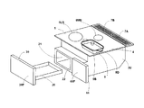
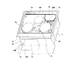
図1〜図9は、実施の形態1に係る加熱調理器を示すものである。
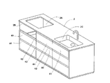
図1〜図9において、本実施の形態の加熱調理器1は、例えば流し台付きの厨房家具(「システムキッチン」ともいう)2に組み込まれる、商用電源200Vとする誘導加熱調理器である。2Aは、厨房家具2に形成された設置口である。前記加熱調理器1は、この設置口2Aの口縁部に載せて支持されている。厨房家具2は、この実施の形態1では図3に示すように、水道2Dから出る水を一時的に貯めることができる水槽2Cを備えている。2Bは、厨房家具2の所定の位置に形成した開口であり、この開口は、加熱調理器1を組み込んだ場合、その正面(後述するカバー30側)を前方へ露出させるためのものである。なお、開口2Cと設置口2Aの大きさは、キッチンの規格によって所定の寸法に形成されている。
1 to 9 show a cooking device according to the first embodiment.
1-9, the
加熱調理器1を厨房家具2に組み込む通常の方法は、図9に示している通りである。この図9は、厨房家具への組み込み作業の途中段階を示す模式図である。この図のように、本体ケース3の前方側(手前側)が下になるように傾けたまま、前記設置口2Aの中に本体ケース3を入れ、その後、本体ケース3の後方側を下げると、加熱調理器1が厨房家具2の設置口2Aの周縁部に載せられた状態になるので、最後にその状態を固定するため、ネジを締めて本体ケース3の周縁部に設置してある固定金具(図示せず)を移動(回動)させ、当該固定金具を厨房家具2に強く押し当てた状態にして設置が完了する。なお、このような設置方法は既に広く採用されているので、詳しい構造については説明を省略する。
A normal method of incorporating the
加熱調理器1は、その外郭を構成する箱型形状の本体ケース3と、この上部に固定された金属製の額縁状の外枠(図示せず)と、この外枠の上面の略全体を覆うように、その上面に重ねて取り付けられた耐熱強化ガラス製のトッププレート4とから構成されている。なお、このトッププレート4は、その下面全体は可視光線が透過しない塗装面で覆われることにより、トッププレート4の上方からは、その下方の機能部品、例えば後述する右側誘導加熱コイル8Rが視認できないようになっている。
The
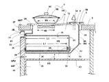
図5において、前記本体ケース3は、薄い金属板をプレス装置による折り曲げ加工して断面U字形に成形した胴部と、この胴部の前方側に溶接やネジ止めによって結合された前板と、胴部の後方側に溶接やネジ止めによって結合された後面板3Hとの3者で、上面全体が開口した本体ケースが構成されている。符号3Uは、胴部又は後面板を示しており、3Bは、胴部の底面部を示している。3Jは、後述するように設置口2Aの中に、加熱調理器1を挿入する場合(図9参照)、後面板3Hが厨房家具2に当たらないように形成された傾斜面部である。このため、本体ケース3の底面部3Bにおいて、後述する収納室21が設置できる範囲は、図5に示しているように前方の挿入口22を基準にして所定の長さ3Kの範囲である。
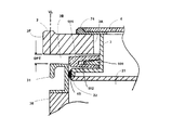
In FIG. 5, the
図5において、BSは、前記後面板3Hと厨房家具2の背面板2Uとの間に形成された空隙である。前記送風機BMは、この空隙から冷却用の空気の全部又は一部を吸引するようにしても良い。また後述するカバー30の下面と、飾り板(「化粧枠」ともいう)44の上面との間には、カバー30の移動を許容するために2cm〜数ミリメートル(mm)程度の空隙GPUが形成されるが、この空隙GPUも前記空隙BSに連通しているので、この前方側の空隙GPUから、送風機BMが空気を導入しても良い。この空隙を利用して吸気する形態にした場合、本体ケース3の上面に吸気口を設置することを省略でき、あるいは吸気口の開口面積を小さくして目立たないようにできるから、上面のデザイン性を向上させることが期待できる。なお、図5において、GPTは、前記カバー30の最上部にある手掛け部31A天面と、厨房家具2の前面にある開口2Bの下面との間に、カバー30の移動を許容するために形成される2cm〜数ミリメートル(mm)程度の空隙である。
In FIG. 5, BS is a gap formed between the
5は、前記外枠の後部に固定された後部枠板であり、吸気口(図示せず)と排気口6(図5参照)がそれぞれ形成されている。7Aは、前記吸気口の上に置かれた吸気カバーであり、通気性を確保するため、互いに並行な複数の細い貫通孔が形成されている。7Bは、前記排気口6の上に置かれた排気カバーであり、通気性を確保するため、互いに並行な複数の細い貫通孔が形成されている。
図1と図4において、8Rは、トッププレート4上の1つの誘導加熱部(「加熱口」ともいう)に合わせてその下方に設置された右側誘導加熱コイルであり、ドーナッツ状形状を有している。同じく、8Lは、トッププレート4上の1つの誘導加熱部に合わせてその下方に設置された左側誘導加熱コイルであり、ドーナッツ状形状を有している。
8Mは、同じくトッププレート4上の1つの誘導加熱部に合わせてその下方に設置された中央誘導加熱コイルであり、ドーナッツ状形状を有している。なお、これら誘導加熱コイルを総称する場合、「加熱コイル」と呼ぶ場合があり、その場合の符号は8を使用する。
また特に8R、8L、8Mを特定する必要がない場合には、「右側」や「左側」という用語を省略する場合がある。さらに、図1、図2、図4では加熱コイル8の位置が円で示されているが、実際には前述したように非透過性であるトッププレート4が上にあるため、使用者にはこれらコイル8を目視することはできない。
In FIG. 1 and FIG. 4, 8R is a right induction heating coil installed below the
8M is a central induction heating coil which is similarly installed below one induction heating section on the
In particular, when it is not necessary to specify 8R, 8L, and 8M, the terms “right side” and “left side” may be omitted. Further, in FIG. 1, FIG. 2, and FIG. 4, the position of the
図1において、8LSは、左側誘導加熱コイル8Lによって誘導加熱できる目安的な位置を表示した円形マークであり、トッププレート4上面に印刷により形成されている。8MSは、中央誘導加熱コイル8Mによって誘導加熱できる目安的な位置を表示した円形マークであり、トッププレート4上面に印刷により形成されている。この他にも、図示していないが、右側誘導加熱コイル8Rによって誘導加熱できる位置を表示した円形マークも、トッププレート4上面に印刷により設けてある。円形マーク8LSの位置と大きさ(直径寸法)は、左側誘導加熱コイル8Lの外径寸法8D(図5参照)に応じて決定される。他の誘導加熱コイルも同様である。
In FIG. 1, 8 LS is a circular mark displaying a guide position where induction heating can be performed by the left
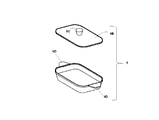
図1及び図4において、9は、平面形状が楕円形又は長方形の調理器具(第1の調理器具)であり、図8に詳しく示しているように、ステンレスや鉄等の磁性金属製の皿部9Aと、この皿部の上方を覆う透明な耐熱ガラス製の蓋体9Bと、から構成されている。9Cは、使用者が蓋体9Bを持ち運ぶための摘みである。また9Dは、皿部9Aの両端部に一体成型された取っ手である。なお、図4に2点鎖線で示した長方形状は、前記皿部9Aの底面の範囲を示しており、皿部9Aの外郭形状を示していない。言い換えると、皿部9A底面の短径寸法は、図4と図5に符号SSで示している通りである。また、皿部9A底面の長径寸法は、図4に符号LSで示している通りである。この第1の調理器具9は、この加熱調理器1のために(この加熱調理器の製造者によって)専用に製造されたものである。
1 and 4, 9 is a cooking utensil (first cooking utensil) having an elliptical or rectangular planar shape, and as shown in detail in FIG. 8, a dish made of magnetic metal such as stainless steel or iron. It is comprised from the part 9A and the
調理器具9の外形形状が、皿部9Aの両端部に取っ手9Dを一体に設けたシンプルな構造であるため、後述する挿入口22から収納室21の中に格納する場合、また逆にその挿入口22を介して取り出す場合でも、使用者は皿部9Aと蓋体9Bを一括して移動でき、便利である
Since the outer shape of the
取っ手9Dは、図示しているように皿部9Aの最も上部に設けると、トッププレート4からの間隔を大きくできる。つまり、このトッププレート4の下方にある誘導加熱コイル8Lから遠くなるため、取っ手9Dが誘導加熱されることを抑制できる。取っ手9Dは、皿部9Aの底面(トッププレート4の上面に近接する面)から5cm以上離れた位置にあることが望ましいが、あまり離すと、それだけ皿部9Aの最大高さ寸法が大きくなり、収納室21や挿入口22の高さ寸法を大きくしなければならない。
If the
図4において、10は、平面形状が円形の調理器具(第2の調理器具)であり、一般に市販されている金属製(少なくとも底面部が、磁性金属製)の大径の鍋である。また、11は、平面形状が円形の調理器具(第3の調理器具)であり、一般に市販されている金属製(少なくとも底面部が、磁性金属製)の小径の鍋である。
In FIG. 4, 10 is a cooking utensil (second cooking utensil) having a circular planar shape, and is a large-diameter pan generally made of metal (at least the bottom portion is made of magnetic metal).
図4から明らかなように、前記第1の調理器具9の短径寸法SSは、前記左側誘導加熱コイル8Lの外径寸法(直径8Dは図5参照)と同等か、それよりも2〜3cm程度大きい。また、右側誘導加熱コイル8Rの上で誘導加熱することに適している第2の調理器具10は、その底面の直径寸法が、右側誘導加熱コイル8Rの外径寸法と同等か、それより3〜4cm程度大きい。さらに、中央誘導加熱コイル8Mの上で誘導加熱することに適している第3の調理器具11は、その底面の直径寸法が、中央誘導加熱コイル8Mの外径寸法と同等か、それより2〜3cm程度大きい。
As is clear from FIG. 4, the short diameter dimension SS of the
図4から明らかなように、トッププレート4の上面において、吸気カバー7Aと排気カバー7Bより前方から、後述する操作部12の後端までの広いエリアは、誘導加熱調理に利用される加熱エリア13である。この「加熱エリア」13という意味は、その全域で加熱コイル8によって誘導加熱できるという意味ではなく、第1〜第3の調理器具9、10、11等を、加熱調理しない場合に一時的に置いたり、あるいは誘導加熱するために置いたりできるという範囲である。HAは、この加熱エリア13の前後方向の長さ、すなわち奥行寸法を示している。
As is clear from FIG. 4, on the upper surface of the
図4から明らかなように、加熱エリア13の前後方向中心線CL2の真下に、前記右誘導加熱コイル8Rと、左誘導加熱コイル8Lの各中心部が位置している。
一方、中央加熱コイル8Mの中心部は、加熱エリア13の左右方向中心線CL1の真下に位置している。
As is clear from FIG. 4, the central portions of the right
On the other hand, the center portion of the
図4において、12は、前記トッププレート4の上面に形成された操作部であり、以下述べるように、使用者が指等で軽く触れた時の静電容量の変化を利用して入力できる方式の各種入力キーを、横方向に一直線状に配置している。
操作部12は、右操作部12R、中央操作部12M及び左操作部12Lの3つを含んでいる。
In FIG. 4, 12 is an operation unit formed on the upper surface of the
The
図4において、14は、後述する制御装置56に商用電源60(図8参照)を供給することと遮断することができる主電源スイッチ61の操作ボタン又は操作キー(タッチ入力式)である。
前記右操作部12Rには、3つのタッチ式入力キー15を配置してある。これら入力キー15は、1つ又は複数の入力機能が割り当てられている。例えば、誘導加熱時の火力(消費電力)や、誘導加熱時間、誘導加熱パターン等である。前記右操作部12Rは、右側誘導加熱コイル8Rの動作開始や停止、その他通電条件(時間や火力等)を指令できるためのものである。
In FIG. 4,
Three touch-
図4において、16は、前記中央操作部12Mに配置した3つのタッチ式入力キーである。この前記中央操作部12Mは、中央誘導加熱コイル8Mの動作開始や停止、その他通電条件(時間や火力等)を指令できるためのものである。
In FIG. 4,
図4において、17は、前記左側操作部12Lに配置した3つのタッチ式入力キーである。この前記左側操作部12Lは、左側誘導加熱コイル8Lの動作開始や停止、その他通電条件(時間や火力等)を指令できるためのものである。
In FIG. 4,
図4において、18は、前記制御装置56に対して無線通信を指令するインターネット接続指令用のタッチ式入力キーである。19は、前記制御装置56に対して、前記第1の調理器具9の存在結果を要求する確認指令用のタッチ式入力キーである。これら2つの入力キー18、19の動作については後で詳しく説明する。
In FIG. 4, 18 is a touch-type input key for internet connection command for commanding wireless communication to the
図4において、20は、トッププレート4の前方中央部に設けた透明の表示窓に対応して、その近傍で真下に配置された長方形状の表示画面であり、例えば液晶表示画面である。この表示画面には、前記操作部12の操作結果が文字や記号等で表示されたり、あるいは前記制御装置56で検知した各種機能部品の動作状況等が表示されたりする。なお、この表示画面は、前記主電源スイッチ61の操作ボタン又は操作キー14を、ONにした以降、前記制御装置56の指令によって表示動作が開始される。
In FIG. 4,
次に、本発明の特徴点の1つである収納室21について説明する。図1と図5に示すように、前記本体ケース3の中に収納室21が区画形成されている。ここで「区画形成」とは、後で説明する「冷却用空間30」との間が物理的な遮蔽物や壁(金属製又はプラスチック製等の壁)で仕切られ、空気の流通が許容されていない状態をいうが、物理的に完全に遮断されているという意味ではなく、例えば複数の金属製薄板同士を連結して壁を形成する場合、一方の薄板に形成した孔に、他方の薄板に形成した爪の先端部を挿入して係合させるという方法を採用した際に、その爪と孔の間に僅かな隙間が形成されても、「区画形成されている」と定義している。もちろん、前面だけが開放されて筒状に一体成型され、気密性を高めた収納室21であっても良い。
Next, the
図1と図5において、22は、収納室21の前面側に形成した開口であり、この開口が前記第1の調理器具9を挿入できる「挿入口」となるので、以下「挿入口」と呼ぶ。
前記収納室21の挿入口22最前縁から、収納室21の背面を構成する後壁23までの距離(奥行寸法)L2は、例えば30cmである。この奥行寸法L2は、取っ手9Dを含めた第1の調理器具9の最大長さよりも大きく設定されており、第1の調理器具9はこの収納室21の中に、前後方向に挿入されて格納できる。なお、収納室21に取り出し自在に格納する物品として、第1の調理器具9が最も大きいため、この調理器具9の外形寸法を考慮して挿入口22の大きさを決定しているが、この収納室21に格納できる他の物品としては、例えば加熱調理器1に付属している取扱説明書や、調理後に特にトッププレート4の上面や操作部12の表面等の簡単な清掃をする洗剤、あるいは別の調理器具10,11(それらに付属する蓋体があれば、その蓋体も含む)がある。
In FIGS. 1 and 5,
A distance (depth dimension) L2 from the foremost edge of the
収納室21の底壁25の上面から天井壁24の下面までの距離(高さ寸法)HSは、摘み9Cまでも含めた調理器具9全体の最大高さ寸法よりも十分大きく、例えば10cmである。更に挿入口22から奥側まで横幅WXは一定である。挿入口22の間口(横幅寸法)は、例えば15cmである。このため収納室21の平面形状は、挿入口22から後方に向かって細長い形、長方形になっている。
The distance (height dimension) HS from the upper surface of the
前記収納室21の挿入口22の大きさ(横幅と高さ寸法)は、前述した調理器具9の皿部9Aと蓋体9Bとを、重ねた状態のまま挿入できるように設定されているので、使用者が格納する場合、蓋体9Bと皿部9Aを分けたり、方向を変えたりする手間は必要なく、使い勝手が良い。
The size (width and height dimensions) of the
挿入口22は、前述した操作部12が位置しているトッププレート4の手前側、すなわち、本体ケース3の前面側が、使用者の作業性の面で望ましいので、実施の形態1では、挿入口22を本体ケース3の前面部に設けている。
Since the
図1と図5において、26は、平面形状が長方形の、浅い容器状の受け皿(本発明でいう「トレイ」に相当)であり、金属製又はプラスチック材料から形成されている。例えばアルミニウム製薄板をプレス成型して形成している。この受け皿26の内側部分の、奥行寸法L1は、前記収納室21の奥行寸法L2よりも1cm程度小さいので、収納室21の内部に、完全に格納できる(図5参照)。
In FIG. 1 and FIG. 5, 26 is a shallow container-like saucer (corresponding to “tray” in the present invention) having a rectangular planar shape, and is made of a metal or plastic material. For example, an aluminum thin plate is formed by press molding. Since the depth dimension L1 of the inner portion of the
受け皿21は、図1に示したように収納室21の中から完全に外へ引き出すことが可能であるが、このように完全に引き出すことができなくとも、図6に示すように、所定範囲まで引き出すことができれば良い。
The
図1、図5及び図6において、30は、正面形状が横長長方形のカバーであり、全体がプラスチックの一体成型で形成されている。31は、カバー30を移動させる際に使用者が指を掛けるハンドルであり、手掛け部31Aを備えている。なお、このハンドル31は、必ずしも必要とせず、例えば、カバー30に手掛け部となる穴や貫通孔を形成して代用しても良い。カバー30と前記受け皿26とは、接着材で一体に連結しても良いし、あるいは、連結金具で連結し、使用者が受け皿26の清掃時に、受け皿26とカバー30を分離できるようにしても良い。図5で、符号29は前記接着材であるが、この接着材は図5では図示を省略してある。
1, 5, and 6,
図1において、44は、正面形状が正方形の右カバー(本発明でいう「飾り板」に相当)であり、全体がプラスチックの一体成型で形成されている。この右カバーは、前記本体ケース3前面において、前記収納室21の挿入口22より右側部分を覆うものである。この右カバーは、前記カバー30と同じ厚みを有し、カバー30の右側に隣接するように本体ケース3前壁面に固定されている。なお、右カバー44とカバー30の高さ寸法は同じであり、またそれら両者の表面の色も同じにしてある。
In FIG. 1,
図5において、45は、本体ケース3の前面で、前記挿入口22の真上位置に取り付けたシール材である。このシール材は、例えばシリコンゴム製等の弾力性に富む素材から形成されており、カバー30で挿入口22を閉鎖した場合、その手掛け部31A背面に先端が接触するようになっている。
In FIG. 5,
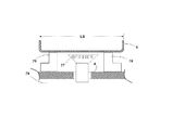
図5において、30Fは、前記カバー30の前面を示しており、この前面は、厨房家具2の中に加熱調理器1を組み込んだ場合、その下方に隣接して存在する扉又は引出し等の家具表面材40と、面一状態となる。言い換えると、加熱調理器1を組み込んだ場合、そのカバー30の前面30Fは、真上から見ると、家具表面材40の前面40Fと一直線上に並ぶ位置となる。そして家具表面材40と、カバー30とは、厨房家具2を前方から、あるいは斜め前方から見ても、統一された平面になっているような意匠感覚を使用者に呈することができる。なお、右カバー44の前面の位置も、前記カバー30の前面30Fの位置と合わせてある。
In FIG. 5, 30F has shown the front surface of the said
同じく図5において、2Fは、厨房家具2の前面(正面)を示している。厨房家具2の中に加熱調理器1を組み込んだ場合、前記カバー30の前面は、この厨房家具2の前面2Fと合致した位置か、それよりも若干(例えば、数mm程度)後退した位置になるように設計させている。図5では、若干後退した位置にしてある例を示している。
Similarly in FIG. 5, 2F has shown the front (front) of the
図3において、41は、前記家具表面材40とは別の位置にある家具表面材である。この家具表面材41は、厨房家具2の中に加熱調理器1を組み込んだ場合、その右側方で隣接して存在する扉又は引出し等の構造物である。前記右カバー44の前面44Fの位置も、この家具表面材41の表面41Fの位置と合わせてある。これによりカバー30の表面と、家具表面材40、41の各表面40F、41Fが、全て同一の垂直面で揃うことになる。
In FIG. 3, 41 is a furniture surface material at a position different from the
図5において、前記カバー43は、厨房家具2の内部を上下に複数の部屋に仕切る壁であり、この壁の下方は、例えば、台所用品や食品等の保存庫49に利用する例が多い。
In FIG. 5, the
以上説明した構成により、厨房家具2の中に加熱調理器1を組み込んだ場合、厨房家具2の前面全体は、略一つの平面を呈する。使用者が厨房家具2を見た場合、全体に前面(正面)が、すっきりした統一感のあるデザインであると認識できるように設計されている。なお、厨房家具2と、加熱調理器1は、同じ製造業者が設計することをこの発明では意図しておらず、実際に、厨房家具は、流し台等の厨房家具、住宅設備業者が製造販売し、加熱調理器1は家電機器業者が製造販売している。なお、前記2種類の家具表面材40、41は同じものであっても良い。またこれら家具表面材は、扉や引き出しのように、前後に移動するものでなくとも良い。例えば厨房家具2の表面に常に固定状態で存在し、全く移動しないものであっても良い。
With the configuration described above, when the
図3と図5において、前記カバー30と、右カバー44のそれぞれの前面30F、44Fの色と表面形態(模様や光沢の有無、凹凸状態等)は、前記家具表面材40、41の前面の色や表面形態と合わせると、更に統一的意匠感が高まる。例えば、家具表面材40、41の正面全体が、単色や木目調で統一されている場合、カバー30の前面30Fと、右カバー44の前面44Fも、同じ単色の色や木目調デザインで統一すれば、この前面30F、44Fだけが厨房家具2の中で目立つこともない。なお、カバー30と家具表面材40、41の前面の色や模様を異ならせ、収納室21の挿入口22を覆うカバー30の存在感を示しても良い。なお、42は、家具表面材40、41の前面に印刷で表示した枠線であり、家具表面材40、41の前面に物理的な凹凸を形成するものではないが、光沢のある金属製の細い板等を張り付けて、高級感を出したものでも良い。
3 and 5, the colors and surface forms (pattern, glossiness, unevenness, etc.) of the
図2に示した厨房家具2では、加熱調理器1を最も左側に組み込んだため、前記右カバー44の右側に前記家具表面材41が隣接した形になったが、厨房家具2の中央部に加熱調理器1を組み込んだ場合には、前記カバー30の左側には、家具表面材41が隣接する一方、右カバー30の右側にも家具表面材41が隣接することになる。このような場合でも、前記したように、加熱調理器1の部分だけが前方へ突出するようなことはなく、厨房家具2の前面全体は、略一つの平面を呈する状態にできる。
In the
図6に示しているように、カバー30を前方に引くと、前記受け皿26を収納室21の中から前方に引き出すことが可能であるが、この引き出し量を一定限度に制限した方が好ましい。受け皿26の中には、前記した第1の調理器具9を載せているため、必要以上に引き出すことを防止し、受け皿26の落下を防止する機構を備えているが、具体的には図示していない。しかし、収納室21受け皿26の後部に突起を設ける一方、収納室21の内側には、前記受け皿26をある限界位置まで引き出した際に当るようなストッパーを設けることで簡単に実現できる。
As shown in FIG. 6, when the
図6において、LDは、カバー30を前方に引いた場合の最大引出し量を示している。この最大引出し量は、前記第1の調理器具9を、受け皿26の上から持ち上げて、収納室21の挿入口22から外へ運び出せる寸法に設定されている。また、この図6に示すように、受け皿26を前方に一定限度まで引き出した状態でも、受け皿26は、略水平に支持される構成になっている。これは、受け皿26の左右両側に設けた溝に、収納室21の左右内側壁面から突出する支持ピン等の剛性のある部材が係合しているからである。図6に示しているように、第1の調理器具9の重量とカバー30の重量を受け皿26が支え、その受け皿26の総重量を、前記収納室21の左右壁面が支えるという形になっている。
In FIG. 6, LD indicates the maximum amount of drawer when the
図5、図6において、50は、受け皿26の後部背面側に取り付けた永久磁石、51は、収納室21の後壁23に設置した磁気感知スイッチ(リードスイッチ)である。受け皿26が収納室21の最も奥の所定位置まで挿入されている場合、加熱調理器1の運転開始準備段階では、前記リードスイッチ51が、永久磁石50の接近を検知するからONを示す信号を出力することとなり、その検出信号は制御装置56に入力されるので、制御装置56では、カバー30が閉鎖されており、加熱調理を開始して良いと判断する。つまり、前記リードスイッチ51は、安全装置SDの一部を構成している。ここでいう「安全装置」は、前記制御装置56とリードスイッチ51の両者によって構成されていることが分かる。
5 and 6,
図6に示しているように、前記収納室21は、前記挿入口22を除いた左右側方と上下面、及び後方側が一連の壁面材51で囲まれ、後述する送風機BMの冷却風が侵入しない閉鎖空間として区画されている。このため、送風機BMの冷却風が収納室21の空間に流入せず所定の風路を流れ、後述する冷却用空間52の冷却効率を低下させないようにしている。
As shown in FIG. 6, the
また前記本体ケース3の内部には、前記閉鎖空間の外側にある冷却用空間52に、前述した3つの誘導加熱コイル8R、8L、8Mと、後述するインバーター回路基板55及び前記送風機BMが配置されている。そして誘導加熱調理の間は、この送風機BMが本体ケース3の内部に新鮮な空気の流れを発生させるから、誘導加熱コイル8R、8L、8Mと、インバーター回路基板55の温度上昇が阻止される。
Further, inside the
前記冷却用空間52は、前記後部枠板5に形成した吸気口(図示せず)を通じて、本体ケース3の外部に連通している。また冷却用空間52は、前記後部枠板5に形成した排気口6(図5参照)を通じて本体ケース3の外部と連通している。
The cooling
図1に戻って、前記本体ケース3の内部構造について説明する。後部枠板5に形成した吸気口(図示せず)には、前記送風機BMを運転すると、矢印53で示す吸気流が発生する。つまり、本体ケース3の右側後方位置で、前記冷却用空間52の上流部分には、前記送風機BMが設置されている。この送風機BMで吸い込んだ冷却用空気の下流側には、前記インバーター回路基板55が配置されており、送風機BMからの冷却用空気流は、インバーター回路基板55の下流で、2つの風路に案内され、1つの風路の下流側には制御装置56が配置され、またもう1つの風路の下流には、前記3つの誘導加熱コイル8R、8L、8Mが、それぞれ配置されている。それら2つの風路を経由した冷却風は、最後には前記後部枠板5に形成した排気口6(図5参照)を通じて本体ケース3の外部へ放出される。なお、冷却風を案内するために、複数のダクトや仕切り板が設置されているが、図示を省略している。
Returning to FIG. 1, the internal structure of the
次に加熱調理器1の制御関係の構成について図8を参照しながら説明する。
61は、使用者によって開閉操作される主電源スイッチで、200Vの商用電源60に電源プラグ(図示せず)介して接続されている。14は使用者によって開閉操作される主電源スイッチ用の操作キー、62は、この主電源スイッチ61を介して電気エネルギーが供給される電源回路、56は、この電源回路から所定の定圧電流が供給され、マイクロコンピューターを中心に構成されている制御装置である。
Next, the control-related configuration of the
前記マイクロコンピューターは、入力部と、出力部と、記憶部と、CPU(演算制御部)の4つの部分から構成され、その記憶部には、各種調理メニューに対応した通電制御プログラムが予め記憶(格納)されている。また、前記マイクロコンピューターの記憶部(ROM、RAM)とは別に、異常監視情報を記録する大容量の記憶装置56Rを内蔵している。
The microcomputer is composed of four parts: an input unit, an output unit, a storage unit, and a CPU (calculation control unit). In the storage unit, energization control programs corresponding to various cooking menus are stored in advance ( Stored). In addition to the microcomputer storage unit (ROM, RAM), a large-
誘導加熱調理中は、電気的な異常状態の有無の監視が制御装置56によって実施されている。そのために図示していないが、前記インバーター回路基板55には、複数の電圧計、電流計(電流センサー)等を備えている。さらに制御装置56は、温度検出回路63から温度情報を得て、加熱調理器の主要な部分が異常な高温度になっていないかどうかを監視している。例えば前記表示画面20は、液晶表示基板で構成されているが、比較的熱に弱いので、所定温度(例えば60℃)を超えないように温度検出回路63を通じて監視しており、前記所定温度を超えた時点で「異常予備状態」と制御装置56によって判定される(なお、異常予備状態は、検出温度が60℃〜65℃の範囲にある場合に限る。65℃を超えると危険度高まり、制御装置56は本当の異常状態と認定する)。
During induction heating cooking, the
この異常予備状態では直ちに加熱動作は停止せず、本体ケース3の内部空間を冷却している送風機(冷却ファン)BMの送風能力を上げることで改善する。しかし65℃を超えた時点で異常状態と制御装置56によって判定され、直ちに加熱動作を停止するため、例えば、右側加熱コイル8Rに高周波電力を供給しているインバーター回路55R(後述する)の電源供給を遮断する。
In this abnormal preparatory state, the heating operation is not immediately stopped, but is improved by increasing the blowing capacity of the blower (cooling fan) BM that cools the internal space of the
そして、少なくともこのような異常予備状態から緊急停止までの期間における加熱調理器1の主要な部分の電気的、物理的(一例として前記した表示画面20の温度)の変化状況を示す(異常監視)情報が、制御装置56の記憶部56Rの中に格納される。なお、記憶部56Rに記憶される異常監視情報は、主電源スイッチ61を入れた時点から取得開始され、調理を停止するまでの電気的、物理的変化の履歴が反映されたものとなる。そのため、その後選択した調理メニュー(例えば、「湯沸し」、「煮込み」、「揚げ物」など)や、誘導加熱の火力の情報も、時系列で記録される。途中で異常状態が原因で緊急停止した場合は、その時点まで異常監視情報が前記記憶装置56Rに保存されることになる。
And the change state of the electrical and physical (temperature of the above-mentioned
またこの実施の形態1では、より広範囲にわたって誘導加熱調理器2の動作を監視してデータを取得するため、主電源スイッチ61をONにしてから誘導加熱調理を緊急停止するまでの期間の監視情報を制御装置56が取得できるようにしている。
In the first embodiment, since the data is acquired by monitoring the operation of the
図4で説明したインバーター回路基板55の中には、3つのインバーター回路55L、55M、55Rを内蔵している。
インバーター回路55Lは、前記左側の誘導加熱コイル8Lに高周波電流を供給するためのものであり、共振コンデンサー等が接続された周知の共振回路に接続されている。
The
The
55Rは、前記右側の誘導加熱コイル8Rに高周波電流を供給するためのインバーター回路である。また55Mは、中央の誘導加熱コイル8Mに高周波電流を供給するためのインバーター回路である。
55R is an inverter circuit for supplying a high frequency current to the
そしてこれら3つのインバーター回路55L、55M、55Rは、前記制御装置56によって互いに独立して駆動されるようになっている。
These three
64は、電子的に作成した音声を合成する音声合成装置であり、使用者に対する操作の案内や、異常発生時の報知などをスピーカー65から音声でその都度報知する。
63は、前記した温度検出回路である。この温度検出回路は、前記した3つの誘導加熱コイル8L、8M、8Rによって加熱されるトッププレート4上の、第1の調理器具9の温度や、そのトッププレート4の温度、冷却用空間52の雰囲気温度、インバーター回路55L、55M、55R、表示画面20等の温度を検知するための複数個の温度センサー(図示せず)から、それぞれ温度検知情報を受け取り、それら温度検出結果を制御装置56に送る。前記温度センサー(図示せず)は赤外線センサーのような非接触型、あるいはサーミスタのような接触型の何れであっても良く、それらを単独で、又は組み合わせて使用している。
63 is the temperature detection circuit described above. This temperature detection circuit includes the temperature of the
66は、リアルタイム・クロックとも呼ばれている時計回路であり、後述する主電源スイッチ61に繋がる電源回路62とは別の専用電源(内蔵電池)BT1から電源が供給され、長期間に亘って駆動されるようになっている。これは例えば電波時計でも良く、常に制御装置56から求めがあれば、現在の日にちと正確な時刻を秒単位で知らせるものであり、この加熱調理器1の製造段階で正しい日時にセットされている。従って、加熱調理器1の主電源を切り、その後再度主電源を投入しても、この時計回路の時刻情報は影響受けず、常に最新の正しい時刻を制御装置56に伝える機能がある。このため、前記制御装置56の記憶装置56Rに記録される異常監視情報も、常に正確な時間が同時に記録されて保存されることになる。
67は、地震発生時の揺れを検知する感振機器であり、所定の震度(加速度)以上を感知した場合、振動感知信号を前記制御装置56に送り、制御装置56ではその信号を受けて地震発生と判断し、使用中の全ての加熱手段の電源を瞬時に遮断する動作を行う。
68は、無線通信手段である。この無線通信手段は、加熱調理器1の本体ケース3に内蔵されたものでも良いし、後述するアダプター形式で加熱調理器1の電源回路62に接続したものでも良いが、この実施の形態1では、アダプター形式を採用している。
前記「アダプター」とは、加熱調理器1のような個々の家電機器とその電源との間に設けられる制御機器をいう。例えばここでいうアダプターとは、特開2011−205821号公報、特開2011−55623号公報に示されるようなアダプターをいい、電源プラグとコンセントを有し、そのコンセントに通電を制御すべき電気機器(この実施の形態1においては、加熱調理器1)を接続する。そして電力指令信号をアダプターが無線通信によって受け取ると、制御すべき家電機器(加熱調理器1)の電源供給を制限し、又は遮断する。このように既存の家電機器(加熱調理器1)にアダプターを接続し、そのアダプターに、家庭内の総電力量を制限する電力制御装置(図示せず)から電力指令信号を送り、その信号によってアダプターが加熱調理器1を制御するので、既存の加熱調理器1にもアダプターを電源側に介在させることで、電力指令装置によって電力を集中制御できる利点が得られる。
The “adapter” refers to a control device provided between an individual home appliance such as the
図4に示したように、操作部12には入力キー18がある。この入力キー18をタッチ操作すると、前記制御装置56は、無線通信手段68を介して、家庭の外部空間にある広域通信回路網に接続し、情報プロバーダーが設置したサーバー(図示せず)から、前記第1の調理器具9の使用に役立つ情報を取得する。取得した情報は、前記記憶装置56Rに格納される。また表示画面20で表示し、あるいはこの表示に加えて更に、音声合成装置64によってスピーカー65から音声で報知される。
As shown in FIG. 4, the
69は、表示画面20を駆動するための駆動回路である。この駆動回路は前記制御装置56と接続されている。なお、この表示部駆動回路69は、図示していないが、表示用メモリー、表示コントローラー、インターフェース、電源回路、コモンドライバー、およびセグメントドライバーを、それぞれ備えている。
以上の構成であるから、次に加熱調理動作について説明する。
次に加熱調理器1の制御関係の構成について図8を参照しながら説明する。
まず、使用者が主電源スイッチ61をONすると、この主電源スイッチを介して電気エネルギーが電源回路62に供給される。そしてこの電源回路から所定の定圧電流が供給され制御装置56が起動される。
制御装置56は、温度検出回路63や、音声合成装置64、表示部駆動回路69を起動し、異常な温度状態が温度検出回路で検出されない場合で、かつ異常な電圧や電流が検出されない場合には、起動時の自己チェック動作を完了する。そして加熱調理開始できる旨を、前記表示画面20で表示し、かつ音声合成装置64でもスピーカーを通じて報知する。
Since it is the above structure, heating cooking operation | movement is demonstrated next.
Next, the control-related configuration of the
First, when the user turns on the
The
そこで、収納室21のカバー30を手前に引出して、第1の調理器具9を取り出して、例えば図4、図5に示すように、左側加熱コイル8Lの真上位置に置く。なお、第1の調理器具9は、皿部9Aだけでも誘導加熱調理に利用できるが、蓋体9Bを同時に使用した方が、被調理物(例えば、魚や肉等)が飛散せず、また熱気が逃げないので、加熱効率が良くなる。
Therefore, the
制御装置56は、起動時の自己チェック動作を完了した後で、前記安全装置SDの一部を構成するリードスイッチ51が開放(OFF)されると、受け皿26が収納室21の最も奥の所定位置から引き出されたものであると判定する。その後、3つの加熱コイル8L、8M、8Rの何れかの上に、金属製の鍋等の被加熱物が置かれたかどうかを、検知する(このような検知方法は既に各種方法が提案されているので詳しい説明は省略する)。
When the
制御装置56は、左側加熱コイル8Lか、又は右側加熱コイル8Rの上に第1の調理器具9があることを検知すると、表示画面20と音声合成装置64によって、加熱調理の条件を操作部12からインプットするように促す。
左側加熱コイル8Lの上に、第1の調理器具9が置かれている場合、左側の操作部12Lにある、3つの入力キー17を使って、火力や加熱時間等を入力し、その入力キー17の1つで加熱開始の指令を入力すれば、インバーター回路55Lが制御装置56によって駆動され、誘導加熱調理が実行される。
When the
When the
このような誘導加熱調理の実行前でも、また実行中、実行後においても、操作部12にある入力キー18をタッチ操作すると、前記制御装置56は、無線通信手段68を介して、家庭の外部空間にある広域通信回路網に接続し、情報プロバーダーが設置したサーバー(図示せず)から、前記第1の調理器具9の使用に役立つ情報をリアルタイムで取得し、取得した情報は、前記記憶装置56Rに格納される一方、表示画面20で表示し、あるいはこの表示に加えて更に、音声合成装置64によってスピーカー65から音声で報知されるので、使用者は、第1の調理器具9を使用する場合に、外部の有益な情報を利用でき、便利である。例えば、魚を焼く場合には、加熱コイル8Lの火力について知ることができる。
When the input key 18 in the
このような誘導加熱調理の実行中、使用者が任意のタイミングで加熱動作を停止できるが、その停止指令は、前記入力キー17の1つで行える。緊急時には、前記主電源スイッチ64の操作キー14を押すことでも簡単に自動停止を行える。
While the induction heating cooking is being performed, the user can stop the heating operation at an arbitrary timing, but the stop command can be issued by one of the
誘導加熱調理を終えた第1の調理器具9は、まず、収納室21のカバー30を手前に引出して、受け皿26を収納室21から前方に引き出し、次に、その受け皿26の上に第1の調理器具9を載せれば良い。仮に第1の調理器具9が、まだ加熱調理の直後であって温度が高くとも、受け皿26は金属や耐熱性のプラスチックで形成されているので、何ら支障はない。
The
制御装置56は、前記安全装置SDの一部を構成するリードスイッチ51がONされると、受け皿26が収納室21の最も奥の所定位置に戻されたことを検知する。この状態は、カバー30が挿入口22を閉鎖した状態でもある。そこで収納室21は、外部との空気の連通がない閉鎖空間に戻ったことになるので、前記したように、まだ高温度の第1の調理器具9の影響で、収納室21の内部雰囲気の温度が上昇することが想定される。しかし、この実施の形態1では、このような温度上昇も考慮して収納室21を設計してあり、本体ケース3の外郭温度やカバー30の表面温度を所定温度以上に上げることはない。
The
収納室21の内部雰囲気の温度上昇を抑制する対策の1つとして、収納室21の背面や天井面等に通気孔を設け、収納室21を冷却用空間52と連通させても良い。その場合、更に積極的に空気で冷却するならば、送風機BMの冷却風の一部が収納室21の内部に導入され、またそこから排出されて、最終的に収納室21の熱気が、前記排気口6(図5参照)からの排気流と同様に、本体ケース3から外部へ放出されるようにしても良い。
As one of the measures for suppressing the temperature rise in the internal atmosphere of the
以上の説明では、第1の調理器具9を使用して誘導加熱調理をした場合であったが、その他の一般の金属鍋やフライパン等の調理器具、すなわち前記した第2、第3の調理器具10、11でも調理は可能である。
In the above description, the
次に、前記制御装置56に対して、前記第1の調理器具9の存在結果を要求する確認指令用のタッチ式入力キー19を操作した場合の制御装置56の動作について説明する。入力キー19を操作されると、収納室21の内部に第1の調理器具9があるかどうかを、制御装置56が検出する。そのために、収納室21には、第1の調理器具9がある場合と、無い場合を判別するセンサー、例えば、受け皿26の上の所定位置に第1の調理器具9があることを、磁気的又は光学的、あるいは重量で検知するセンサーを別途設けている。そして、前記カバー30が開放され、その後閉鎖されたことを前記リードスイッチ51で検知した場合、その開放前と後の磁気的、光学的又は重量(受け皿26を含めた重量で良い)の変化を判定して、金属製であり、比較的に重量がある(例えば、500g以上はある)第1の調理器具9の存在を検知している。第1の調理器具9がある場合、入力キー19を操作した時から直ぐに、その調理器具9の有無が、表示画面20で表示され、又は音声合成装置64で報知されるので、使用者は、例えば右側の加熱コイル8Lの上で別の加熱調理をしている場合であっても、前記カバー30を前方に引き出さずに、第1の調理器具9の格納状態を直ぐに確認できるため、便利である。
Next, the operation of the
実施の形態1の総括
以上の説明から明らかなように、この実施の形態1の加熱調理器1は、第1の発明の構成を備えていた。
すなわち、この実施の形態1における第1の発明になる加熱調理器1は、
厨房家具2に組み込まれて使用されるものであって、上部にトッププレート4が設けられ、前記厨房家具2に支持される本体ケース3と、
本体ケース3の前面に形成された挿入口22から後方側に連続して当該本体ケース3の内部に設けられた収納室21と、
本体ケース3内部に配置された電気エネルギーによって加熱機能を発揮する加熱コイル8L、8M、8Rと、
前記挿入口22の前方側を開閉自在に塞ぐように前記本体ケース3に取り付けられるカバー30と、を備え、
前記加熱コイル段8L、8M、8Rは、前記トッププレート4の上方に置かれた状態の被調理物を収容する金属製の第1の調理器具9を加熱でき、
前記収納室は、前記挿入口から挿入された物品を、取り出し可能に格納できる大きさを有し、
前記カバー30は、前記挿入口22を閉じた状態で、その左側又は右側の少なくとも何れか一方に隣接する前記厨房家具2の前面41Fと合わせた位置に設置されるものである。
Summary of
That is, the
A
A
Heating coils 8L, 8M, and 8R that exert a heating function by electrical energy disposed inside the
A
The
The storage chamber has a size that allows the articles inserted from the insertion port to be removably stored,
The
この第1の発明になる加熱調理器1によれば、本体ケース3の内部に設けられた収納室21に、その前方の挿入口22から、少なくとも第1の調理器具9を挿入して格納できる。また必要な都度、その調理器具9を簡単に取り出すことができる。しかも、厨房家具2に組み込まれた状態では、加熱調理器1の前面を覆うカバー30が、その左側又は右側の少なくとも何れか一方に隣接する厨房家具2の家具表面材41の前面41Fと大きな段差を生ずることがない。
According to the
以上の説明から明らかなように、この実施の形態1の加熱調理器1は、第2の発明の構成を備えていた。
すなわち、この実施の形態1における第2の発明になる加熱調理器1は、
厨房家具2に組み込まれて使用されるものであって、上部にトッププレート4が設けられ、前記厨房家具に支持される本体ケース3と、
この本体ケース3の前面に形成された挿入口22から後方側に連続して当該本体ケースの内部に設けられた収納室21と、
前記トッププレート4の下方に配置された誘導加熱コイル8L、8M、8Rと、
前記本体ケース3の内部に収納され前記誘導加熱コイル8L、8M、8Rに高周波電力を供給するインバーター回路55L、55M、55Rと、を備え、
前記誘導加熱コイル8L、8M、8Rは、前記トッププレート3の上方に置かれた状態の被調理物を収容する金属製の第1の調理器具9を加熱でき、
前記本体ケース3の前面には、前記挿入口22を開閉自在に塞ぐためのカバー30と、このカバー30と隣接するように前記本体ケース3の前面に取り付けられた飾り板(右カバー)44と、を備え、
前記収納室21は、前記第1の調理器具9を前記挿入口22から挿入して格納できる大きさを有し、
前記カバー30は、前記挿入口22を閉じた状態で、その左側又は右側の少なくとも何れか一方に隣接する前記飾り板44の前面位置と合され、当該飾り板44はそれと隣接する厨房家具2の前面と合わせた位置に設置されるものである。
As is apparent from the above description, the
That is, the
A
A
Induction heating coils 8L, 8M, 8R arranged below the
An
The
On the front surface of the
The
The
この第2の発明になる加熱調理器1によれば、本体ケース3の内部に設けられた収納室21に、その前方の挿入口22から第1の調理器具9を挿入して格納できる。しかも、厨房家具2に組み込まれた状態では、加熱調理器1の前面を覆うカバー30と飾り板44の双方が、その左側又は右側の少なくとも何れか一方に隣接する厨房家具3の前面41Fと大きな段差を生ずることがないので、加熱調理器1前面と厨房家具2の前面との全体に、統一的平面感を持たせることができる。
According to the
以上の説明から明らかなように、この実施の形態1の加熱調理器1は、第3の発明の構成を備えていた。
すなわち、この実施の形態1における第3の発明になる加熱調理器1は、
厨房家具2に組み込まれて使用されるものであって、
上部にトッププレート4が設けられ、前記厨房家具2に支持される本体ケース3と、
この本体ケースの前面に形成された挿入口22から後方側に連続して当該本体ケース3の内部に設けられた収納室21と、
本体ケース3内部に配置された電気エネルギーによって加熱機能を発揮する加熱コイル8L、8M、8Rと、
前記挿入口の前方側を開閉自在に塞ぐように前記本体ケース3に取り付けられるカバー30と、
このカバーと連結されており、カバーの前後方向の移動に伴って前記収納室内21を前後方向に移動するトレイ(受け皿)26と、を備え、
前記加熱コイル8L、8M、8Rは、前記トッププレート4の上方に置かれた状態の被調理物を収容する金属製の第1の調理器具9を加熱でき、
前記収納室21は、前記調理器具9が前記挿入口22から挿入されて前記トレイ26の上に格納できる大きさを有し、
前記カバー30は、前記挿入口22を閉じた状態で、その左側又は右側の少なくとも何れか一方に隣接する前記厨房家具2の前面41Fと合わせた位置に設置され、
前記カバー30を前方に移動させて前記挿入口22を開けた状態で、前記トレイ26に載せられた前記調理器具9が、当該挿入口22から外部に露出するものである。
As is clear from the above description, the
That is, the
It is built into the
A
A
Heating coils 8L, 8M, and 8R that exert a heating function by electrical energy disposed inside the
A
A tray (a tray) 26 that is coupled to the cover and moves in the
The heating coils 8L, 8M, and 8R can heat the metal
The
The
The
この第3の発明になる加熱調理器1によれば、本体ケース3の内部に設けられた収納室21に、その前方の挿入口22から金属製の調理器具9を挿入して格納できる。しかも、厨房家具2に組み込まれた状態では、加熱調理器1の前面を覆うカバー30が、その左側又は右側の少なくとも何れか一方に隣接する厨房家具2の前面41Fと大きな段差を生ずることがない。さらに、カバー30と一体化されているトレイ26よって調理器具9を前方へ引き出すことができ、使用者の操作性を向上させることができる。
According to the
さらに、この実施の形態1の加熱調理器1は、第4の発明の構成を備えていた。
すなわち、この実施の形態1における第4の発明になる加熱調理器1は、
厨房家具2に組み込まれて使用されるものであって、
上部に第1の調理器具9を支えるためのトッププレート4が設けられ、前面に前記調理器具9の挿入口22となる開口部を有し、前記厨房家具2に支持される本体ケース3と、
前記挿入口22に連続して前記本体ケース3の内部に設けられた前記調理器具9が収納可能な収納室21と、
前記挿入口22の前方側を開閉自在に塞ぐように前記本体ケース3に取り付けられるカバー30と、
前記トッププレート4の下方に配置された誘導加熱コイル8L、8M、8Rと、
前記本体ケース3の内部に収納され前記誘導加熱コイル8L、8M、8Rに高周波電力を供給するインバーター回路55L、55M、55Rと、
前記インバーター回路55L、55M、55Rの動作を制御する制御装置56と、を備え、
前記カバー30は、前記挿入口22を閉じた状態で、その左側又は右側の少なくとも何れか一方に隣接する前記厨房家具2の前面41Fと合わせた位置に設置されるものであり、
前記制御装置56には、前記カバー30が開いている状態を検知し、当該カバーが開いている状態では前記インバーター回路55L、55M、55Rの動作開始を禁止する安全装置SD(50、51)を設けているものである。
Furthermore, the
That is, the
It is built into the
A
A
A
Induction heating coils 8L, 8M, 8R arranged below the
A
The
The
この第4の発明になる加熱調理器1によれば、本体ケース3の内部に設けられた収納室21に、その前方の挿入口22から金属製の調理器具9を挿入して格納できる。しかも、厨房家具2に組み込まれた状態では、加熱調理器1の前面を覆うカバー30が、その左側又は右側の少なくとも何れか一方に隣接する厨房家具2の前面41Fと大きな段差を生ずることがない。さらに、前記カバー30が開いている状態では前記インバーター回路55L、55M、55Rの動作開始が自動的に禁止されるので、安全性を高めることができる。
According to the
さらに、この実施の形態1の加熱調理器1は、第5の発明の構成を備えていた。
すなわち、この実施の形態1における第5の発明になる加熱調理器1は、
厨房家具2に組み込まれて使用されるものであって、
上部に第1の調理器具9を支えるためのトッププレート4が設けられ、前面に前記調理器具9の挿入口22となる開口部を有し、前記厨房家具2に支持される本体ケース3と、
前記挿入口22に連続して前記本体ケース3の内部に設けられた前記調理器具9が収納可能な収納室21と、
前記挿入口22の前方側を開閉自在に塞ぐように前記本体ケース3に取り付けられるカバー30と、
前記トッププレート4の下方に配置された誘導加熱コイル8L、8M、8Rと、
前記本体ケース3の内部に収納され前記誘導加熱コイル8L、8M、8Rに高周波電力を供給するインバーター回路55L、55M、55Rと、
前記インバーター回路55L、55M、55Rの動作を制御する制御装置56と、
前記誘導加熱コイル8L、8M、8Rを冷却するための空気を前記本体ケース3の外部から取り込む送風機BMと、を備え、
前記収納室21は、前記挿入口22を除いた左右側方と上下面、及び後方側が一連の壁面材で囲まれ、前記送風機の冷却風が流れない閉鎖空間として区画され、
前記本体ケース3の内部には、前記閉鎖空間の外側にある冷却用空間52に、前記誘導加熱コイル8L、8M、8R、インバーター回路55L、55M、55R及び前記送風機BMが配置され、
前記冷却用空間52に通ずる外気の導入口と外部に通じる排気口6を前記本体ケース3に形成し、
前記カバー30は、前記挿入口22を閉じた状態で、その左側又は右側の少なくとも何れか一方に隣接する前記厨房家具2の前面41Fと合わせた位置に設置されるものである。
Furthermore, the
That is, the
It is built into the
A
A
A
Induction heating coils 8L, 8M, 8R arranged below the
A
A blower BM that takes in air for cooling the
The
Inside the
An external air introduction port that communicates with the cooling
The
この第5の発明になる加熱調理器1によれば、本体ケース3の内部に設けられた収納室21に、その前方の挿入口22から金属製の第1の調理器具9を挿入して格納できる。しかも、厨房家具2に組み込まれた状態では、加熱調理器1の前面を覆うカバー30が、その左側又は右側の少なくとも何れか一方に隣接する厨房家具2の前面41Fと大きな段差を生ずることがない。さらに、前記本体ケース3の内部には、前記収納室21が閉鎖空間として区画され、この閉鎖空間とは隔絶された冷却用空間52が形成され、この冷却用空間52に存在する誘導加熱コイル8L、8M、8R、インバーター回路55L、55M、55Rが、前記送風機BMで導入された空気によって冷却されるので、加熱調理器1の運転中に温度が上昇する誘導加熱コイル8L、8M、8Rと、インバーター回路55L、55M、55Rを構成する電力制御素子等の重要な電気・電子部品の過熱を防止できる。
According to the
さらに、この実施の形態1の加熱調理器1は、第6の発明の構成を備えていた。
すなわち、この実施の形態1における第6の発明になる加熱調理器1は、
厨房家具2に組み込まれて使用されるものであって、
上部に第1の調理器具9を支えるためのトッププレート4が設けられ、前面に前記調理器具9の挿入口22となる開口部を有し、前記厨房家具2に支持される本体ケース3と、
前記挿入口22に連続して前記本体ケース3の右側又は左側寄り内部に前後方向に細長く設けられ、前記調理器具9が収納可能な収納室21と、
前記挿入口22の前方側を開閉自在に塞ぐように前記本体ケース3に取り付けられるカバー30と、
前記トッププレート4の下方に配置された誘導加熱コイル8L、8M、8Rと、
前記本体ケース3の内部に収納され前記誘導加熱コイルに高周波電力を供給するインバーター回路55L、55M、55Rと、
前記インバーター回路55L、55M、55Rの動作を制御する制御装置56と、
前記誘導加熱コイル8L、8M、8Rを冷却するための空気を前記本体ケース3の外部から取り込む送風機BMと、を備え、
前記調理器具9は、短径寸法SSと長径寸法LSを有し平面形状が楕円形又は長方形状であり、
前記挿入口22の間口(横幅寸法)は、前記短径寸法SSよりも幅広に形成され、
前記カバー30は、前記挿入口22を閉じた状態で、その左側又は右側の少なくとも何れか一方に隣接する前記厨房家具2の前面41Fと合わせた位置に設置されるものである。
Furthermore, the
That is, the
It is built into the
A
A
A
Induction heating coils 8L, 8M, 8R arranged below the
A
A blower BM that takes in air for cooling the
The
The opening (lateral width dimension) of the
The
この第6の発明になる加熱調理器1によれば、本体ケース3の内部に設けられた収納室21に、その前方の挿入口22から金属製の調理器具9を挿入して格納できる。しかも、厨房家具2に組み込まれた状態では、加熱調理器1の前面を覆うカバー30が、その左側又は右側の少なくとも何れか一方に隣接する厨房家具2の前面41Fと大きな段差を生ずることがない。さらに、前記収納室21は、前記本体ケース3の内部の右側又は左側寄りに前後方向に細長く設けられ、この収納室21の内部空間形状に合わせて前記調理器具9は楕円形又は長方形状であるため、当該調理器具9で秋刀魚等の細長い被調理物も調理でき、しかも収納室21が左右どちらかの方向に位置しているため、本体ケース3の内部に格納すべき、誘導加熱コイル8L、8M、8R、インバーター回路55L、55M、55R、制御装置56及び送風機BMの設置空間を確保できる。
According to the
さらに、この実施の形態1の加熱調理器1は、第7の発明の構成を備えていた。
すなわち、この実施の形態1における第7の発明になる加熱調理器1は、
厨房家具2に組み込まれて使用されるものであって、
上部に第1の調理器具9を支えるためのトッププレート4が設けられ、
前面に前記調理器具9の挿入口22となる開口部を有し、前記厨房家具2に支持される本体ケース3と、
前記挿入口22に連続して前記本体ケース3の内部に設けられ前記調理器具9が収納可能な収納室21と、
前記挿入口22の前方側を開閉自在に塞ぐように前記本体ケース3に取り付けられるカバー30と、
前記トッププレート4の下方に配置された誘導加熱コイル8L、8M、8Rと、
前記本体ケースの内部に収納され前記誘導加熱コイル8L、8M、8Rに高周波電力を供給するインバーター回路55L、55M、55Rと、
前記インバーター回路55L、55M、55Rの動作を制御する制御装置56と、
前記制御装置56に使用者が入力信号を与えることができる操作部12と、
外部から前記制御装置56の制御に関する情報を取得する無線通信部68と、を備え、
前記カバー30は、前記挿入口22を閉じた状態で、その左側又は右側の少なくとも何れか一方に隣接する厨房家具2の前面41Fと合わせた位置に設置されるものであり、
前記操作部12には、前記調理器具9を使用する場合に、前記無線通信部68を介して調理参考情報を取得することを指令する指令スイッチ18を備えているものである。
Furthermore, the
That is, the
It is built into the
A
A
A
A
Induction heating coils 8L, 8M, 8R arranged below the
A
An
A
The
The
この第7の発明になる加熱調理器1によれば、本体ケース3の内部に設けられた収納室21に、その前方の挿入口22から金属製の調理器具9を挿入して格納できる。しかも、厨房家具2に組み込まれた状態では、加熱調理器1の前面を覆うカバー30が、その左側又は右側の少なくとも何れか一方に隣接する厨房家具2の前面41Fと大きな段差を生ずることがない。さらに、前記調理器具9を収納室21から取り出して使用する際に、調理に参考となる情報を外部から無線通信で取得することができるので、上記調理器具9を使う場合の利便性を高めることができる。
According to the
実施の形態2
図10〜図11は、実施の形態2に係る加熱調理器を示すものである。この実施の形態では、加熱調理器1の本体を、上部ユニットと下部ユニットに二分化したところが特徴である。なお、図1〜図9と同一又は相当部分には同一符号を付し、重複する説明は省略する場合がある。
10 to 11 show a cooking device according to the second embodiment. This embodiment is characterized in that the main body of the
図10に示すように、この実施の形態2の加熱調理器1の本体ケース3は、左側加熱コイル8L、右側加熱コイル8R及び中央加熱コイル8Mからなる加熱部を内蔵した上部ユニットTUと、収納室21を内蔵した下部ユニットKUが、別々に形成されたところが特徴である。
As shown in FIG. 10, the
上部ユニットTUの外郭を構成する本体ケース3は、胴部3Uと、この胴部の底面全体を覆うようにネジ等で胴部に結合される、1枚の底板3Bとから構成されている。3Cは、本体ケース3に底板3Bを結合するためのネジを挿通させるネジ孔である。なお、前記胴部3Uと底板3Bは、いずれも薄い金属板から構成されている。この胴部3Uの外径寸法は、厨房家具2の設置口2Aの口径よりも小さいので、実施の形態1(図9参照)で示したように、設置口2Aの中に挿入できる。
The
一方、下部ユニットKUは、その外郭を構成するものが、箱形状の下部本体ケース70である。この下部本体ケース70には、前記左側加熱コイル8L、右側加熱コイル8R及び中央加熱コイル8Mからなる加熱部を収納しないので、全体をプラスチック材料で形成しても良い。つまり、下部本体ケース70には、前記左側加熱コイル8Lや、インバーター回路基板55等の重要な電気部品、発熱部品を格納していないこと、また強度が要求されるトッププレート4を下方から支持する構造物ではないので、実施の形態1のように、薄板金属の箱構造にして前後や左右を完全に囲む必要がなく、下部本体ケース70の構成は簡略化でき、製造コストを大幅に下げることができる。
On the other hand, the lower unit KU is a box-shaped lower
この図10に示した実施の形態2では、前記上部ユニットTUの内部に、前記した加熱コイル8R、8L、8Rの他に、制御装置56、インバーター回路基板55及び前記送風機BMが配置されている。つまり、主要な電気部品や機能部品は全て上部ユニットTUの中に収容されている。なお、BMは送風機、55はインバーター回路基板を示している。
In the second embodiment shown in FIG. 10, in addition to the heating coils 8R, 8L, and 8R, the
厨房家具2の中に組み込む場合には、まず下部ユニットKUを、設置口2Aから挿入して所定位置に固定し、その次に、その上方から上部ユニットTUを載せて、上部ユニットTUを厨房家具2の設置口2Aの周縁部に支持させることで良い。なお、下部ユニットKUの上に上部ユニットTUを載せて、先に両者を固定金具等で着脱可能に連結し、このような連結物を、次に設置口2Aから挿入して、厨房家具2の所定位置に設置しても良い。
When incorporating into the
この図10に示した実施の形態2によれば、加熱部を内蔵した上部ユニットTUと、収納室21を内蔵した下部ユニットKUが、別々に形成できるので、実施の形態1で示したような、大きな本体ケースをプレス加工等で形成する必要がなく、また本体ケース3自体が小型化されるので、重量が軽減でき、コスト削減が期待できる。また下部ユニットKUの外郭ケースを単独で形成できるので、本体ケース3を構成する金属材よりも比較的軽量なプラスチック材を使用できる。これらにより全体的に大幅な製造コストと重量の低減が期待できる。
According to the second embodiment shown in FIG. 10, the upper unit TU having a built-in heating unit and the lower unit KU having a built-in
図11に示したものは、図10に示した実施の形態2の変形例を示したものである。
この図11の上部ユニットTUには、図10で示した底板3Bはない。つまり上部ユニットTUの底面は開放されたままである。しかしながら、送風機BMやインバーター回路基板等の主要部品は、上部ユニットTUの外郭を構成する本体ケース3の内部に形成した支持物に固定されている。
一方、下部ユニットKUは、その外郭を構成するものが、箱形状の下部本体ケース70である。そして下部本体ケース70の天井面には、前記上部ユニットTUの本体ケース3にネジ等で固定するためのフランジ70R、70B、70Lが形成されている。各フランジには、ネジを挿通するためのネジ孔71が事前に形成されている。この下部本体ケース70には、前記左側加熱コイル8L、右側加熱コイル8R及び中央加熱コイル8Mからなる加熱部を収納しないので、全体をプラスチック材料で形成しても良い。
FIG. 11 shows a modification of the second embodiment shown in FIG.
The upper unit TU shown in FIG. 11 does not have the
On the other hand, the lower unit KU is a box-shaped lower
厨房家具2の中に組み込む場合には、まず下部ユニットKUの上に上部ユニットTUを載せて、前記フランジのネジ穴71を利用してネジで両者を結合する。このようにして全体を一つのユニット化した上で、それを設置口2Aから挿入して所定位置に固定することで良い。
When incorporating in the
この図11に示した実施の形態2によれば、加熱部を内蔵した上部ユニットTUと、収納室21を内蔵した下部ユニットKUが、別々に形成できるので、実施の形態1で示したような、大きな本体ケースをプレス加工等で形成する必要がなく、また本体ケース3自体が小型化されるので、重量が軽減でき、コスト削減が期待できる。また下部ユニットKUの外郭ケースを単独で形成できるので、本体ケース3を構成する金属材よりも比較的軽量なプラスチック材を使用できる。これらにより全体的に大幅な製造コストと重量の低減が期待できる。
According to the second embodiment shown in FIG. 11, the upper unit TU incorporating the heating unit and the lower unit KU incorporating the
この図10、図11に示した実施の形態2の変形例として、前記飾り枠44を廃止し、飾り枠44がある部分まで前記カバー30を右側方向に延長し、下部本体ケース70の前面全体を前記カバー30で覆うようにすれば良い。
このように、下部本体ケース70の全体を1枚のカバー30で覆う構成に変更した場合、飾り枠44のような、隣接する部材と、カバー30との水平方向の平面度を合致させる必要がなくなる。つまり、カバー30と、隣接する厨房家具2の家具表面材40、41の位置合わせが簡単になる。これによりカバー30の表面と、家具表面材40、41の各表面40F、41Fが、全て同一の垂直面で簡単に揃うことになる。
As a modification of the second embodiment shown in FIGS. 10 and 11, the
As described above, when the lower
実施の形態2の総括
以上の説明から明らかなように、この実施の形態2の加熱調理器1は、第8の発明の構成を備えていた。
すなわち、この実施の形態2における第8の発明になる加熱調理器1は、
厨房家具2に組み込まれて使用されるものであって、
上部にトッププレート4が設けられ、前記厨房家具2に支持される上部本体ケース(上部ユニットTUの本体ケース)3と、
この上部本体ケース3と連結された(下部ユニットの)下部本体ケース70と、
前面に形成された挿入口22から後方側に連続して前記下部本体ケース70の内部に設けられた収納室21と、
前記上部ケース内部3に配置された電気エネルギーによって加熱機能発揮する加熱手段(加熱コイル8L、8M、8R)と、
前記挿入口22の前方側を開閉自在に塞ぐように前記下部本体ケース70に取り付けられるカバー30と、を備え、
前記加熱手段(加熱コイル8L、8M、8R)は、前記トッププレート4の上方に置かれた状態の被調理物を収容する金属製の第1の調理器具9を加熱でき、
前記収納室21は、前記調理器具9を前記挿入口22から挿入して格納できる大きさを有し、
前記カバー30は、前記挿入口22を閉じた状態で、その左側又は右側の少なくとも何れか一方に隣接する前記厨房家具2における家具表面材41の前面41Fと合わせた位置に設置されるものである。
Summary of
That is, the
It is built into the
An upper main body case (main body case of the upper unit TU) 3 provided with a
A lower body case 70 (of the lower unit) connected to the
A
A heating means (heating coils 8L, 8M, 8R) that exerts a heating function by electrical energy disposed in the
A
The heating means (heating coils 8L, 8M, 8R) can heat the
The
The
この第8の発明になる加熱調理器1によれば、上部本体ケース3と別に形成され、上部本体ケースに結合される下部本体ケース70内部の収納室21に、その前方の挿入口22から金属製の調理器具9を挿入して格納できる。しかも、厨房家具2に組み込まれた状態では、加熱調理器1の前面を覆うカバー30が、その左側又は右側の少なくとも何れか一方に隣接する厨房家具の前面と大きな段差を生ずることがない。なお、カバー30は、その下方に隣接する厨房家具2における家具表面材40の前面40Fとも、垂直な平面同士を揃えることができる。
According to the
実施の形態3
図12〜図13は、本発明の実施の形態3に係る加熱調理器を示すものである。この実施の形態3では、加熱調理器1の本体ケースの内部に収納室21を形成し、その収納室の前面の挿入口22を覆うカバー30が、本体ケース3の前面全体を覆うようにしたところが特徴である。なお、図1〜図9と同一又は相当部分には同一符号を付し、重複する説明を省略する場合がある。
12 to 13 show a cooking device according to
本体ケース3の前面の、例えば左側には、収納室21の挿入口22が設けられている。また、本体ケース3の前面には、その挿入口22を開閉するためのカバー30が取り付けられている。このカバー30は、例えばプラスッチック材料で形成され、本体ケース3の前面の下部に設けられたヒンジ部(図示せず)を軸として、下端部30Bが回動自在に取り付けられている。30Aは、カバー30の内側に、挿入口22の大きさに合致させて形成した凹部であり、収納室21の内部空間体積を少しでも大きくするための工夫である。また31は、使用者が掴むことができるようなハンドルである。なお、このハンドルではなく、使用者の指先が挿入される手掛け用の凹部をカバー30の前面側に形成しても良い。
An
図12、図13において、72は、トッププレート4を下方から支える金属製の額縁状の外枠であり、本体ケース3の上端部に固定されている。74は、排気カバー7Bの真下の位置に形成した排気孔であり、冷却用空間52に連通している。75は、送風機BM、インバーター回路基板55等の電気部品ユニットを支持する制御盤である。
(図示せず)
In FIGS. 12 and 13, 72 is a metal frame-like outer frame that supports the
(Not shown)
このように、本体ケース3の全体を1枚のカバー30で覆う構成であるため、実施の形態1で説明した飾り枠44のような、隣接する部材と、カバー30との平面度を合致させる必要がなくなる。つまり、カバー30と、隣接する厨房家具2の家具表面材40、41の位置合わせが簡単になる。これによりカバー30の表面と、家具表面材40、41の各表面40F、41Fが、全て同一の垂直面で簡単に揃うことになる。
Since the
この実施の形態3においても、加熱調理器1を厨房家具2に組み込む通常の方法は、実施の形態1(図9参照)に示したものと同じである。本体ケース3の前方側(手前側)が下になるように傾けたまま、厨房家具2の前記設置口2Aの中に本体ケース3を入れ、その後、本体ケース3の後方側を下げると、加熱調理器1の外枠72が、厨房家具2の設置口2Aの周縁部上面に載せられた状態になる。つまり、加熱調理器1の重量は、プレス加工等で剛性を高めてある金属製の額縁形状の外枠72で受けるから、この外枠の上に載せてあるトッププレート4が、加熱調理器1の重量を受ける訳ではない。
Also in the third embodiment, the normal method for incorporating the
実施の形態3の総括
以上の説明から明らかなように、この実施の形態3の加熱調理器1は、第1の発明の構成を備えていた。
すなわち、この実施の形態3における第1の発明になる加熱調理器1は、
厨房家具2に組み込まれて使用されるものであって、上部にトッププレート4が設けられ、前記厨房家具2に支持される本体ケース3と、
本体ケース3の前面に形成された挿入口22から後方側に連続して当該本体ケース3の内部に設けられた収納室21と、
本体ケース3内部に配置された電気エネルギーによって加熱機能を発揮する加熱コイル8L、8M、8Rと、
前記挿入口22の前方側を開閉自在に塞ぐように前記本体ケース3に取り付けられるカバー30と、を備え、
前記加熱コイル段8L、8M、8Rは、前記トッププレート4の上方に置かれた状態の被調理物を収容する金属製の第1の調理器具9を加熱でき、
前記収納室21は、前記調理器具9が前記挿入口22から挿入されて格納できる大きさを有し、
前記カバー30は、前記挿入口22を閉じた状態で、その左側又は右側の少なくとも何れか一方に隣接する前記厨房家具2の前面41Fと合わせた位置に設置されるものである。
Summary of
That is, the
A
A
Heating coils 8L, 8M, and 8R that exert a heating function by electrical energy disposed inside the
A
The
The
The
この第1の発明になる加熱調理器1によれば、本体ケース3の内部に設けられた収納室21に、その前方の挿入口22から第1の調理器具9を挿入して格納できる。しかも、厨房家具2に組み込まれた状態では、加熱調理器1の前面全体を覆うカバー30が、その左側又は右側の少なくとも何れか一方に隣接する厨房家具2の家具表面材41の前面41Fと大きな段差を生ずることがない。
According to the
実施の形態4
図14は、本発明の実施の形態4に係る加熱調理器を示すものである。この実施の形態4では、加熱調理器1の加熱部は、天然ガスやプロパンガス等を燃料とするガスバーナー77を備えたところが特徴である。なお、図1〜図9と同一又は相当部分には同一符号を付し、重複する説明を省略する場合がある。
FIG. 14 shows a heating cooker according to
図14において、76は、前記ガスバーナー77の周囲を囲むように、一定間隔で4個又はそれ以上の数で、環状に配置した五徳(支持脚)である。第1の調理器具9は、五徳76の上に置かれて、前記ガスバーナー77の炎によって加熱される。なお、この調理器具9も、平面形状が楕円形であり、短径寸法LSは、互いに向い合う五徳76同士の対向間隔よりも大きい。
In FIG. 14,
以上の説明から明らかなように、この実施の形態4に示す加熱調理器1は、第9の発明の構成を備えている。
すなわち、この実施の形態4における第9の発明になる加熱調理器1は、
厨房家具2に組み込まれて使用されるものであって、
上部にトッププレート4が設けられ、前記厨房家具2に支持される本体ケース3と、
この本体ケース3の前面に形成された挿入口22から後方側に連続して当該本体ケース3の内部に設けられた収納室21と、
前記トッププレート4より上方に配置された五徳76と、
当該五徳の上に置かれて使用され、かつ被調理物を収容するための金属製の調理器具9を、ガス燃焼エネルギーによって加熱する加熱手段(ガスバーナー77)と、
前記挿入口22の前方側を開閉自在に塞ぐように前記本体ケース3に取り付けられるカバー30と、を備え、
前記収納室21は、前記調理器具9を前記挿入口22から挿入して格納できる大きさを有し、
前記カバー30は、前記挿入口22を閉じた状態で、その左側又は右側の少なくとも何れか一方に隣接する前記厨房家具2の家具表面材41の前面41Fと合わせた位置に設置されるものである。
この第9の発明になる加熱調理器1によれば、本体ケース3の内部に設けられた収納室21に、その前方の挿入口22から金属製の調理器具9を挿入して格納できる。しかも、厨房家具2に組み込まれた状態では、加熱調理器1の前面を覆うカバー30が、その左側又は右側の少なくとも何れか一方に隣接する厨房家具2の家具表面材41の前面41Fと大きな段差を生ずることがない。
As is clear from the above description, the
That is, the
It is built into the
A
A
A heating means (gas burner 77) that heats the
A
The
The
According to the
実施の形態5
図15〜図17は、本発明の実施の形態5に係る加熱調理器を示すものであり、第10の発明に関する加熱調理器1を示す。
この実施の形態5では、加熱調理器1の加熱部の形態と、左側誘導加熱部に特徴がある。なお、図1〜図9と同一又は相当部分には同一符号を付し、重複する説明を省略する場合がある。
FIGS. 15-17 shows the heating cooker which concerns on
The fifth embodiment is characterized in the form of the heating part of the
図15〜図17において、この実施の形態5の加熱調理器は、左側の誘導加熱部と右側の誘導加熱部と中央加熱部とを備えた、いわゆる3口の誘導加熱調理器であり、平面視で横長矩形(横長方形ともいう)の本体ケース3を備えている。
15 to 17, the heating cooker according to the fifth embodiment is a so-called three-mouth induction heating cooker including a left induction heating unit, a right induction heating unit, and a central heating unit. A
本体ケース3は、外形形状が流し台等の厨房家具2に形成した設置口2Aを覆う大きさに合わせて、外形形状が設定されている。
金属製薄板から形成された本体ケース3の胴部3Uは、内側寸法で横幅W3が540mm(又は550mm)、奥行DP1が402mmの箱形に設計されている。この本体ケース3の内部に前記第1左加熱コイル8L、右加熱コイル8R及び中央加熱コイル8Mが、それぞれ設置されている。胴部3Uの平面的な大きさは図17で分かる。
The outer shape of the
The
トッププレート4は、図16に示すように長方形である。このトッププレート4を構成する耐熱性の強化ガラス板は、横幅W2が728mm、奥行寸法DP2は前記奥行寸法DP1よりも大きい。
The
図15、図16において、8Mは、中央加熱コイルであり、最大外形寸法DM1は100〜120mm程度である。
8Rは、中央加熱コイルであり、最大外形寸法DM3は、200mm程度である。
15 and 16, 8M is a central heating coil, and the maximum external dimension DM1 is about 100 to 120 mm.
8R is a central heating coil, and the maximum outer dimension DM3 is about 200 mm.
8Lは、左側加熱コイルである。MCは左側誘導加熱コイル8Lの中心部にある主加熱コイルであり、被加熱物を載せるトッププレート4に接近して配置されている。第15、図16図中、破線の円で示したものが、金属の鍋等の被加熱物の底面部分の範囲である。
またこの主加熱コイルは、中心点X1を基点として外形形状が円形になるようにして最終的に円盤形にコイル線を巻いて成形されている。主加熱コイルMCの直径(最大外径寸法)DA2は約180mm程度である。この実施の形態5では例えば、定格最大消費電力(最大火力)2000Wの能力を備えている。主加熱コイルは、環状の内側コイルと、これに直列接続された環状の外側コイルの2つの部分で構成されている。
8L is a left side heating coil. MC is a main heating coil in the center of the left
The main heating coil is formed by winding a coil wire in a disc shape so that the outer shape is circular with the center point X1 as a base point. The diameter (maximum outer diameter dimension) DA2 of the main heating coil MC is about 180 mm. In the fifth embodiment, for example, the rated maximum power consumption (maximum thermal power) is 2000 W. The main heating coil is composed of two parts, an annular inner coil and an annular outer coil connected in series therewith.
SC1〜SC4は、4個の長円形副加熱コイルであり、前記主加熱コイルMCの中心点X1を基点として前後・左右に、かつ等間隔で、それぞれ対称的に配置されている。
4個の副加熱コイルSC1〜SC4は、前記主加熱コイルMCの外周面に所定の空間(数mmから10mm程度の大きさ。以下の説明では「5mm」の例で説明する)の空間を保って、コイルベース板(図示せず)の上面に固定されている。
4つの副加熱コイルSC1〜SC4は、平面的形状が同じで、縦・横・高さ(厚さ)寸法も全て同一寸法である。従って1つの副加熱コイルを4個製造し、それを4箇所に配置している。
SC1 to SC4 are four oval sub-heating coils, which are symmetrically arranged in the front-rear, left-right, and equidistant directions with the central point X1 of the main heating coil MC as a base point.
The four sub-heating coils SC1 to SC4 maintain a predetermined space (a size of about several mm to 10 mm. In the following description, an example of “5 mm”) is maintained on the outer peripheral surface of the main heating coil MC. The coil base plate (not shown) is fixed to the upper surface.
The four sub-heating coils SC1 to SC4 have the same planar shape, and the vertical, horizontal, and height (thickness) dimensions are all the same. Accordingly, four sub-heating coils are manufactured and arranged at four locations.
これら4つの副加熱コイルSC1〜SC4は図15に示すように、中心点X1から半径R1の主加熱コイルMCの周囲において、その接線方向が丁度各副加熱コイルSC1〜SC4の長手方向の中心線と一致している。言い換えると長径方向と一致している。
副加熱コイルSC1〜SC4は、それぞれの集合線が長円形に湾曲しながら伸びて電気的に一本の閉回路を構成している。また主加熱コイルMCの垂直方向寸法(高さ寸法、厚さともいう)と各副加熱コイルSC1〜SC4の垂直方向寸法は同じであり、しかもそれら上面と前記トッププレートの下面との対向間隔は同一寸法になるように水平に設置、固定されている。
4つの副加熱コイルSC1〜SC4の最も外側を囲む円の直径は、例えば300mmである。このため、この左側加熱コイル8Lでは、底面の直径が320〜350mm程度の被加熱物に対応できる。
These four sub-heating coils SC1 to SC4 are, as shown in FIG. 15, around the main heating coil MC having a radius R1 from the center point X1, and the tangential direction is exactly the center line in the longitudinal direction of each of the sub-heating coils SC1 to SC4. Is consistent with In other words, it coincides with the major axis direction.
The sub-heating coils SC1 to SC4 each constitute a single closed circuit electrically extending while the respective collecting wires are bent into an oval shape. Further, the vertical dimension (also referred to as height dimension and thickness) of the main heating coil MC and the vertical dimension of each of the sub-heating coils SC1 to SC4 are the same, and the facing distance between the upper surface and the lower surface of the top plate is as follows. It is installed and fixed horizontally to have the same dimensions.
The diameter of the circle surrounding the outermost sides of the four sub-heating coils SC1 to SC4 is, for example, 300 mm. For this reason, the
図15は、左側誘導加熱コイル8Lに電力供給するための回路ブロック図である。左側加熱部の主加熱コイルMCのための主インバーター回路55LMと、4つの副加熱コイルSC1〜SC4毎に接続されている専用の副インバーター回路55LS1、55LS2、55LS3、55LS4を備える。
FIG. 15 is a circuit block diagram for supplying power to the left
55Rは、右側誘導加熱コイル8Rのためのインバーター回路、55Mは、中央誘導加熱コイル8Mのための駆動回路である。
前記右側誘導加熱コイル8Rは、環状に巻かれた1つの加熱コイルと、この加熱コイルと並列になっている外側の加熱コイルとの二重構成であり、2つの加熱コイルは、別々のタイミングで独立して加熱駆動することができる。そのために、前記インバーター回路55Rの構成は、実施の形態1のインバーター回路55Rの構成とは異なっている。具体的には2つの加熱コイルの、それぞれに専用のインバーター回路55R1と55R2を備えている。図15では2つのインバーター回路55R1、55R2を纏めて、符号55Rで表示している。
55R is an inverter circuit for the right
The right
以下具体的に説明すると、前述したように、右側の加熱コイル8Rの最大外形DA3は、200mmであるが、これは外側の環状コイルの外径である。
内側の環状コイルの最大外形は約100mmである。
このため、例えば内側の環状コイルだけを駆動して、小径(例えば80mm〜120mm程度)の被加熱物Nを誘導加熱することができる一方、外側環状コイルと内側環状コイルを同時に駆動して(又は短時間に交互通電して)、より大きな直径、例えば220mm程度のものも加熱できる。
Specifically, as described above, the maximum outer diameter DA3 of the
The maximum outer shape of the inner annular coil is about 100 mm.
For this reason, for example, only the inner annular coil can be driven to inductively heat the object N having a small diameter (for example, about 80 mm to 120 mm), while the outer annular coil and the inner annular coil are simultaneously driven (or Larger diameters, for example about 220 mm, can also be heated by alternating energization in a short time.
主インバーター回路55LMと副インバーター回路55LS1〜55LS4は、商用電源60からの電力がコンバーター(図示せず)を介して直流電流で供給されるので、その直流電流を高周波電流に変換し、それぞれ主加熱コイルMCおよび副加熱コイルSC1〜SC4に(互いに)独立して供給できる。
The main inverter circuit 55LM and the sub inverter circuits 55LS1 to 55LS4 are supplied with electric power from the
一般に、誘導加熱コイルのインピーダンスは、誘導加熱コイルの上方に載置された被加熱物Nの有無および大きさ(面積)に依存して変化するから、これに伴って前記主インバーター回路55LMと副インバーター回路55LS1〜55LS4に流れる電流量も変化する。この実施の形態5では、主加熱コイル55MCと副加熱コイルSC1〜SC4に流れる、それぞれの電流量を検出するための電流検出部(検出手段)80Aを有する。この電流検出部は、後述する被加熱物載置判断部80の一種である。
In general, the impedance of the induction heating coil changes depending on the presence and size (area) of the object N to be heated placed above the induction heating coil. The amount of current flowing through inverter circuits 55LS1 to 55LS4 also changes. In the fifth embodiment, there is a current detection unit (detection means) 80A for detecting respective current amounts flowing in the main heating coil 55MC and the sub-heating coils SC1 to SC4. This electric current detection part is a kind of the to-be-heated object mounting
この実施の形態5では、電流検出部80Aを用いて、主加熱コイルMCと副加熱コイルSC1〜SC4に流れる電流量を検出することにより、それぞれのコイルの上方に被加熱物が載置されているか否か、または被加熱物の底部面積が所定値より大きいか否かを推定し、その推定結果を制御装置56に伝達するので、被加熱物の載置状態について精度よく検出することができる。なお、ここでいう被加熱物とは、実施の形態1で説明したような、第1の調理器具9、第2の調理器具10、第3の調理器具11の全てを含んでいる。
In the fifth embodiment, the
この実施の形態5では、図示のように、制御装置56は、電流検出部80Aに接続されており、被加熱物の載置状態に応じて、主インバーター回路55LMと副インバーター回路55LS1〜55LS4に制御信号を与えるものである。すなわち、制御装置56は、電流検出部80Aで検出された主加熱コイルMCと副加熱コイルSC1〜SC4に流れる電流量に関する信号(被加熱物の載置状態を示すデータ)を受け、被加熱物が載置されていないか、あるいは被加熱物の直径が所定値(例えば120mm)より小さいと判断した場合には、それら主加熱コイルMCと副加熱コイルSC1〜SC4への高周波電流の供給を禁止又は(既に供給開始されている場合はそれを)停止するように主インバーター回路55LMと副インバーター回路55LS1〜55LS4を選択的に制御する。
In the fifth embodiment, as shown in the figure, the
この実施の形態5によれば、制御装置56は、被加熱物の載置状態に応じた制御信号を主インバーター回路56LMと副インバーター回路55LS1〜55LS4に供給することにより、主加熱コイルMCと副加熱コイルSC1〜SC4への給電を互いに独立して制御することができる。また、中央にある主加熱コイルMCを駆動せず(OFF状態とし)、かつ、すべての副加熱コイルSC1〜SC4を駆動する(ON状態とする)ことにより、フライパンなどの鍋肌(鍋の側面)だけを予熱するといった調理方法も実現可能となる。
According to the fifth embodiment, the
図15において、82は、前記主加熱コイルMCを構成する外側の環状コイルと、内側の環状コイルの間に確保された空間に、温度検出素子を設置した温度センサーである。例えば、赤外線を検知して温度を感知する温度センサーである。この温度センサーも、前記被加熱物載置判断部80の一部を構成している。つまり、第1の調理器具9等の被加熱物が、左加熱コイル8Lの上に置かれて誘導加熱が開始されると、その被加熱物がある温度以上になれば、この温度センサーによって存在が検知される。
In FIG. 15,
図17において、83は、収納室21と同様に、前方に挿入口84を備えた第2の収納室である。この収納室83は、鍋等の調理器具を収納するためのものではない。加熱調理器1の使用説明書等を収容するためのものである。
In FIG. 17, 83 is the 2nd storage chamber provided with the
30は、プラスチック製のカバーであり、前記2つの収納室21、83の双方の挿入口22、84を同時に開閉できるよう、正面から見て横長長方形である。
この実施の形態5では、送風機BMは、前記第2の収納室83の背後側の壁面に設けた多数の吸込孔(図示せず)から、本体ケース3の外部の空気を吸込む。そして矢印86で示すように、インバーター回路基板85を冷却した後の空気が、本体ケース3の後部の排気口6(図示していない)から排出される。
In the fifth embodiment, the blower BM sucks air outside the
87は、厨房家具の家具表面材である。この家具表面材87の前面87Fと、前記カバー30とは、上方から見て、横一線上に並ぶように、カバー30の厚みと前後方向の位置が管理されている。これにより、カバー30を取り付けた状態では、前面の位置が揃う。
87 is a furniture surface material for kitchen furniture. The thickness of the
なお、第2の収納室83を設けずに、実施の形態1に示したように、飾り枠44をカバー30の右隣に設置しても良い。
Note that the
図16に示した第1の調理器具9は、内側の底面形状が楕円形である。その底面の長径寸法LSは、例えば280mmである。そして、この第1の調理器具9は、その両側に設けた取っ手9Dを含めた最大長さが、例えば320mmである。このため、前記収納室21の奥行寸法L2(330mm)の範囲に収まる。
The
また、第1の調理器具9は、図16に示したように、右側加熱コイル8Rによって加熱した場合には、第1の調理器具9が楕円形であり、底面の長径寸法LSは、280mmであるから、最大外形DA3が200mmの右側加熱コイル8Rでは小さすぎる。つまり、第1の調理器具9の両端部が十分に加熱できない懸念がある。
Further, as shown in FIG. 16, when the
これに対して、左側加熱コイル8Lは、前述したように、4つの副加熱コイルSC1〜SC4の最も外側を囲む円の直径は、例えば300mmであり、この左側加熱コイル8Lでは、底面の直径が320〜350mm程度の被加熱物に対応できる。
前述したように、制御装置56は、被加熱物の載置状態に応じた制御信号を主インバーター回路56LMと副インバーター回路55LS1〜55LS4に供給する。図17のように主加熱コイルMCと、これを挟んで両側にある2つ副加熱コイルSC2、SC3の上に、第1の調理器具9がある場合には、主インバーター回路56LMと、2つの副インバーター回路55LS2、55LS3の3つのインバーター回路が、制御装置56によって選定され、それらに対し、個々に(同時又は時間差で)高周波電力が印加される。これにより、例えば、第1の調理器具9の中に、細長い魚(例えば、秋刀魚)を入れて魚焼きをする場合でも、その第1の調理器具9底面全体を誘導加熱できるから、魚全体を加熱できる。
On the other hand, in the
As described above, the
なお、左側加熱コイル8Lは、図16に示したように、主加熱コイルMCだけの加熱もできるので、この左側加熱コイル8Lでは、大きさや平面形状の異なる多種類の金属製被加熱物に対応できる。そして、秋刀魚のような長い被調理物を調理できるように楕円形や長方形に形成した第1の調理器具9であっても、その調理器具の大きさに対応して、駆動に必要な副加熱コイルSC1〜SC4が制御装置56によって自動的に選択できる構成であるから、使用者の利便性を向上させることができる。
As shown in FIG. 16, the
さらにこのような長い第1の調理器具9であっても、図17に示しているように、この本体ケース3の前面に形成された挿入口22から後方側に連続して当該本体ケース3の内部に収納室21を形成しているので、大きな第1の調理器具9であっても収納できる。
Furthermore, even in such a long
実施の形態5の総括
以上の説明から明らかなように、この実施の形態5の加熱調理器1は、第10の発明の構成を備えている。
すなわち、この実施の形態5における第10の発明になる加熱調理器1は、
厨房家具2に組み込まれて使用されるものであって、
上部にトッププレート4が設けられ、前記厨房家具2に支持される本体ケース3と、
この本体ケースの前面に形成された挿入口22から後方側に連続して当該本体ケース3の内部に設けられた収納室21と、
前記トッププレート4の下方に配置された誘導加熱コイル8Lと、
前記本体ケース3の内部に収納され前記誘導加熱コイル8Lに高周波電力を供給するインバーター回路と、
底面の形状が長方形又は楕円形の金属製調理器具9が置かれたことを検知し、前記誘導加熱コイル8Lに対する電力供給を制御する制御装置56と、を備え、
前記誘導加熱コイル8Lは、平面形状が円形の中心コイル(主加熱コイル)MCと、この中心コイルMCの周囲にあって、当該中心コイルMCとは独立して電力が供給される、1つ又は複数個の副加熱コイルSC1〜SC4とから構成されており、
前記中心コイルMCと、副加熱コイルSC1〜SC4の両方の上方に及ぶように前記調理器具9が置かれて誘導加熱調理を行う場合、前記制御装置は前記中心コイルと当該副加熱コイルの双方に電力を供給する制御を行い、
前記本体ケース3の前面には、前記挿入口22を開閉自在に塞ぐためのカバー30を備え、前記収納室は、前記調理器具9を前記挿入口22から挿入して格納できる大きさを有し、
前記カバー30は、前記挿入口22を閉じた状態で、その左側又は右側の少なくとも何れか一方に隣接する前記厨房家具2の前面41Fと合わせた位置に設置されるものである。
Summary of
That is, the
It is built into the
A
A
An
An inverter circuit housed inside the
A
The
When the
The front surface of the
The
この第10の発明になる加熱調理器によれば、本体ケースの内部に設けられた収納室に、その前方の挿入口から金属製の調理器具を挿入して格納できる。しかも、厨房家具に組み込まれた状態では、加熱調理器の前面を覆うカバーが、その左側又は右側の少なくとも何れか一方に隣接する厨房家具の前面と大きな段差を生ずることがないので、加熱調理器前面と厨房家具の前面との全体に、統一的平面感を持たせることができる。
さらに、前記誘導加熱コイルは、中心コイルと独立して電力が供給される副加熱コイルを備えており、その副加熱コイルと中心コイルの協同加熱時には、加熱できる範囲が大きくなるので、円形以外の大きな調理器具であっても加熱調理に使用でき、しかもそのような調理器具は、使用しない場合には、前記収納室21に格納できるから、使用時、非使用時の双方で利便性を高めることができる。
According to the cooking device according to the tenth aspect of the present invention, a metal cooking utensil can be inserted into the storage chamber provided inside the main body case from the front insertion port and stored. Moreover, in the state of being incorporated in the kitchen furniture, the cover that covers the front surface of the cooking device does not cause a large step with the front surface of the kitchen furniture adjacent to at least one of the left side or the right side of the cooking device. A uniform flatness can be given to the entire front surface and the front surface of the kitchen furniture.
Furthermore, the induction heating coil includes a sub-heating coil to which power is supplied independently of the center coil. Since the sub-heating coil and the center coil can be heated together, the range that can be heated increases. Even large cooking utensils can be used for cooking, and such cooking utensils can be stored in the
実施の形態6
図18〜図20は、本発明の実施の形態6に係る加熱調理器を示すものである。この実施の形態6では、加熱調理器1の電力量を制御するシステムと連携させたところが特徴である。なお、図1〜図9と同一又は相当部分には同一符号を付し、重複する説明を省略する場合がある。
18 to 20 show a heating cooker according to
この実施の形態6で「HEMS」とは、ホームエネルギー・マネジメント・システムのことをいい、家庭における電力の消費をリアルタイムで統合的に管理するシステムである。
この実施の形態で「電力指令装置」とは、前記HEMSの中核を構成する装置である。
In the sixth embodiment, “HEMS” refers to a home energy management system, and is a system that integrally manages power consumption in a home in real time.
In this embodiment, the “power command device” is a device constituting the core of the HEMS.
図18は、本発明の加熱調理器1を台所で使用している1つの家屋の例を示している。この図において、HAは1つの家屋の居住空間を示す。この居住空間には、家屋の外部にある電力会社の商用電源60から、例えば200Vの電力が供給されている。その電力は、電力量計90を介して家屋の内部に引き込まれている。
FIG. 18 shows an example of one house where the
91は、前記商用電源60にブレーカーBK介して接続された電源線(主幹線)である。前記電源線には、この家屋の中で使用される主要な家電機器EEが接続されている。具体的には、空気調和機92、照明器具93、加熱調理器1が、それぞれ接続されている。なお、図18においては、空気調和機92、照明器具93、加熱調理器1は、それぞれ1つしか示されていないが、複数個あっても良い。
94は、ブレーカーBKを介して電力が供給される電力指令装置であり、キッチンの壁面等のように、家族が容易に接近できる場所に壁掛け状態で設置されているか、又は床面の上に置いてある。 94 is an electric power command device to which electric power is supplied through the breaker BK, and is installed in a wall-mounted state where the family can easily approach, such as the wall surface of the kitchen, or placed on the floor surface. It is.
空気調和機92や加熱調理器1は、電力指令装置94との間で、無線通信により要求電力、実施する調理のメニュー(種類)や使用許可する電力等の情報伝達が行われ、電力指令装置94が許可した上限電力値以下の範囲で、それら空気調和機92や加熱調理器1の消費電力が制御されるようになっている。空気調和機92や加熱調理器1には、無線通信のために実施の形態1で説明したような無線通信手段68を備えている。
The air conditioner 92 and the
前記空気調和機92や照明器具93、加熱調理器1を総称して「家電機器」EEという。
95は、電力指令装置94と広域通信回路網98とを接続するルーターである。これにより電力指令装置94は家屋の外部の電力会社やその他の外部機関96Aのサーバーに接続される。このため、例えば官公庁やその地域の電力会社などの外部機関96Aから、電力逼迫情報などが送信された場合、その情報は、電力指令装置94で受信する。
The air conditioner 92, the lighting fixture 93, and the
A router 95 connects the power command device 94 and the wide
前記「電力逼迫情報」とは、各家庭の使用電力を強制的に下げる指令と、強制的ではなく任意で下げて欲しいという要請レベルの指令の少なくとも2種類がある。なお、電力指令装置94は、電力指令装置94側で取得した情報(家電機器EEから取得した情報や指令信号を含む)を外部の前記広域通信回路網98へ送信する機能も有している。
The “power tightness information” includes at least two types of commands: a command for forcibly reducing the power used in each household and a command at a request level for requesting that the power consumption be reduced arbitrarily. The power command device 94 also has a function of transmitting information acquired on the power command device 94 side (including information and command signals acquired from the home appliance EE) to the external
96Bは、情報サーバーであり、家電機器EEに対して、主に制御用のソフトウェアを提供する手段及び情報提供手段として機能する。この情報サーバーは、家電機器EEの製造業者(メーカ)、販売業者、修理業者、あるいは情報サービス提供業者、電力事業者等の組織が、単独で、又は2つ以上の組織が共同で設置しており、加熱調理器1を含む家電機器EEに関する各種サービスを、広域通信回路網98を介して利用者に提供するものである。
前記情報サーバー96Bには、家電機器EEのアプリケーション・ソフトウェアを記憶し、また改善ソフトウェアを蓄積している改善ソフトウェア(対策プログラム)提供部Sと、家電機器EEの使用者を特定する利用者特定用データベースと、家電機器EEの製造業者(メーカ)が提供した技術情報を蓄積したメーカ側情報データベースと、が設けられている。
The
前記情報サーバー96Bは、一般に「Webサーバー」(以下「ウェブサーバー」という)と呼ばれているもので良い。
前記情報サーバー96Bには、電力指令装置94からのログインIDやパスワードなどの利用者固有情報、ルーター95のネットワークアドレス(MACアドレス)などの設定情報、特定の家電機器EEの種類、型名といった固有の情報が記憶されている。つまり、記情報サーバー96Bは、前記家電機器EE、例えば加熱調理器1から得られた情報に基づいて、その加熱調理器1の適当な使用方法や注意情報等を、蓄積してあるデータベースから検索可能であり、その検索結果を提供する機能を備えている。
The
The
情報サーバー27には、家電機器EEの特定の機種モデルに対応して、家電機器EEの動作プログラムの内容を改善した「改善ソフトウェア」が保管してあり、それを電力指令装置94が広域通信回路網94を介して入手した場合、当該改善ソフトウェアは、電力指令装置94の入出力部家電機器EE側へ提供される。改善ソフトウェアは、1回提供されるだけではなく、必要に応じ、さらに改善したバージョン・アップ版が提供される場合がある。 The information server 27 stores “improvement software” that improves the contents of the operation program of the home appliance EE corresponding to a specific model of the home appliance EE, and the power command device 94 uses the wide area communication circuit. When obtained via the network 94, the improvement software is provided to the input / output unit home appliance EE side of the power command device 94. The improved software is not only provided once, but further improved versions may be provided as necessary.
加熱調理器1が運転開始される直前の状態では、電力指令装置94は、家電機器EEから、空気調和運転に必要とする電力の情報を受信しており、その後、加熱調理器1の運転開始の段階になると、この加熱調理器1からも必要な電力の要求情報を受けるので、電力指令装置94では、要求のあった電力値を集計し、集計された合計電力が、ブレーカーBKの上限容量を超えるかどうかを判断し、比較結果から問題なければ、要求電力に対して許可信号を発信する。
In the state immediately before the
電力指令装置94が、家電機器EEからの電力要求を受ける最初の時点は、家電機器EEの主電源が投入された時点又は動作開始指令が行われた時点である。加熱調理器1では、主電源スイッチ61がONにされた後、加熱口が選定され、調理メニュー(例えば、自動調理メニューでの「炊飯」等)が選択され、又は手動調理メニュー(例えば、「湯沸かし」)のための火力が設定された時点(又は遅くともその火力設定が確定して加熱動作開始された時点)である。
The first time point when the power command device 94 receives a power request from the home appliance EE is when the main power of the home appliance EE is turned on or when an operation start command is issued. In the
電力指令装置94へ要求電力を送信した結果に対し、結局電力指令装置94からOKの返信がなければ、その要求電力での運転は開始されない。OKの信号を受信した場合、運転が開始できる。 If there is no response from the power command apparatus 94 to the result of transmitting the required power to the power command apparatus 94, the operation with the requested power is not started. When an OK signal is received, operation can be started.
家電機器EEは、その電源投入から電源遮断までの全工程において、運転情報(調理メニューの実行や、火力の設定など)が随時電力指令装置94に送信されるので、電力指令装置94は、常に家電機器EEの電力使用状況を把握することができる。 Since the home appliance EE transmits operation information (execution of cooking menu, setting of thermal power, etc.) to the power command device 94 at any time in all processes from power-on to power-off, the power command device 94 is always The power usage status of the home appliance EE can be grasped.
(加熱調理器の基本動作)
次に、本実施の形態6に係る加熱調理器1の誘導加熱動作について、図19〜図20を参照しながら説明する。
(Basic operation of the cooking device)
Next, the induction heating operation of the
図19に示したフローチャートは、加熱調理器1の基本的な動作ステップを示すものである。この動作ステップを決定するコンピュータ・ソフトウエアは、制御装置56に事前に格納されている。
The flowchart shown in FIG. 19 shows the basic operation steps of the
図19において、主電源スイッチ61の操作キー14を使用者がタッチして、電源を入れる(S1)。すると制御装置56に電源が印加され、制御装置56は、温度検出回路63から温度情報を得て、加熱調理器の主要な部分(例えば、加熱コイル8や表示画面20、インバーター回路基板55)が異常な高温度になっていないかどうかを自己チェックする(S2)。
In FIG. 19, the user touches the
異常が発見されない場合、制御装置56は電力指令装置94に対して無線通信手段68を介して、異常のないことの判定情報を送信する。
If no abnormality is found, the
制御装置56は、表示画面20の駆動回路69を起動し、異常がないこと、調理を開始できることを表示する。またこれと同時に、音声合成装置64によって表示画面20で表示した内容と同様な内容を音声で報知する(S3)。
The
その後、表示画面20では、金属製鍋等の被加熱物を、使用したい加熱口の上に置くように、使用者に動作を促す文字を表示する(S4)。
Thereafter, the
このステップ(S4)の段階では、表示画面20には、前記した第1の調理器具9を使用するのか、あるいは一般の金属鍋やフライパン等の調理器具を使用したいのか、選択することを進める文字が表示される。
ここで使用者が、左側操作部12Lにおける特定の入力キー17に触れると、左側の加熱コイル8Lを選択し、汎用の調理器具10,11を使用することを選択したことになる。またその左側操作部12Lにおける別の特定入力キー17に触れると、側の加熱コイル8Lを選択し、かつ第1の調理器具9を使用することを選択したことになる(S5、S6)。
In the stage of this step (S4), the
Here, when the user touches a specific input key 17 in the
ステップS5において、第1の調理器具9を使用することを選択した場合、加熱のメニューを選択するステップ(S7)に進むことになる。
If it is selected in step S5 that the
一方、ステップS6において汎用の調理器具10,11を使用することを選択した場合、通常の加熱調理メニューの選択ステップS8に進む。
On the other hand, when it is selected in step S6 that the general-
加熱のメニューを選択するステップ(S7)に進むと、専用に用意してある第1の調理器具9を使用して、ロースト調理か、炊飯の何れかを選択することになる。仮に、ロースト調理のメニューを選択すると、第1の調理器具9を収納室21から取り出して、左側加熱コイル8Lの上方に置くように、表示画面20で表示され、かつ音声合成装置64でも報知される。
If it progresses to the step (S7) which selects the menu of a heating, it will select either roast cooking or rice cooking using the
図20に示したフローチャートは、第1の調理器具9を使用して、加熱調理メニューの中の「炊飯」を行う場合の基本的な動作ステップを示すものである。
The flowchart shown in FIG. 20 shows basic operation steps in the case of performing “rice cooking” in the cooking menu using the
図20において、S7は加熱調理のメニューから「炊飯」を選択するステップである。
「炊飯」というメニューの選択が行われると、電力指令装置94に対して、所定の起動情報が送信され、電力指令装置94では加熱調理器1によって加熱調理が開始される段階にあることが分かる(S10)。また「炊飯」の場合には、事前に消費電力が決定されているので、例えば「1400W。炊飯時間40分」のように、必要となる電力値や運転時間の情報が電力指令装置94に送信される(S10)。
In FIG. 20, S7 is a step of selecting “cooking rice” from the cooking menu.
When the menu item “cooking rice” is selected, predetermined activation information is transmitted to the power command device 94, and it is understood that the power command device 94 is in a stage where cooking by the
情報サーバー96Bから電力指令装置9は、時間帯別電気料金の情報や、炊飯を上手く行うための参考情報(例えば、古いお米を炊飯する場合には、事前に水を吸わせておく)を取得し、その情報は加熱調理器1に送信される。
このため、加熱調理器1では、それら取得した情報を内部の記憶装置56Rに格納する(S11)。なお、このような時間帯別電気料金は、毎日変更されるものではないので、数日置きに取得しても良く、その数日間は記憶装置56Rに記憶した情報をその都度利用するようにしても良い。
The
For this reason, the
次に加熱調理器1は、表示画面20において取得した時間帯別電気料金や、炊飯を上手く行うための参考情報の情報を表示し、また音声合成装置64によって、それら取得情報の概略が音声で報知される(S12)。
Next, the
次のステップ(S13)では、使用者が更に詳細な情報を求めているかどうかを確認する。例えば、上記ステップ(S12)の表示や音声での報知の際に、「詳しい情報が欲しい場合は、○○キーにタッチして下さい」のような案内を行う。これに応じて使用者が特定の入力操作を左側操作部12Lで行った場合、次のステップ(S14)に進む。
In the next step (S13), it is confirmed whether or not the user is requesting more detailed information. For example, guidance such as “If you want more information, please touch the XX key” is provided when displaying the above step (S12) or notifying by voice. In response to this, when the user performs a specific input operation on the
次のステップ(S14)では、加熱調理器1は電力指令装置9に対して、情報サーバー96Bから取得した情報の詳細を提供するよう要求する。なお、情報サーバーから取得した情報を全て加熱調理器1に送信した場合には、詳細情報が無いことを示す信号を、電力指令装置94から加熱調理器1へ送信する。
In the next step (S14), the
詳細情報の要求がない場合、使用者から炊飯開始を指令する入力キー17による入力があると(S15)、制御装置56は、インバーター回路55Lを駆動し、所定の炊飯工程(吸水工程→沸騰工程→むらし工程)を開始する(S16)。
なお、制御装置56に格納された炊飯プログラムによる炊飯工程が終了すると、前記インバーター回路55Lへの通電は停止する。なお、炊飯に引き続き、保温工程を実行させる場合には、炊飯時よりも小電力でインバーター回路55Lが駆動される。
When there is no request for detailed information, when there is an input from the user with the
In addition, when the rice cooking process by the rice cooking program stored in the
以上の説明では、「炊飯」を行う場合について、電力指令装置94から取得する情報について例を示したが、例えば、第1の調理器具9によって、別の被調理物(肉や魚)を焼く場合についても、調理に参考になる情報(例えば、加熱コイル8Lの火力の調節等)の情報が取得できる。なお、加熱動作が開始される前に、加熱動作の終了時間を予約しても良い。これは一般にタイマー調理と呼ばれており、調理開始前にタイマーを設定(例えば15分間)すると、加熱開始時点から15分間を計算し(実施の形態1で示した、時計回路66の動作で)、15分経過時点で自動的に加熱動作が終了する。
In the above description, in the case of “cooking rice”, an example of information acquired from the power command device 94 has been shown. For example, another cooking object (meat or fish) is baked by the
実施の形態7
図21〜図24は、本発明の実施の形態7に係る加熱調理器を示すものである。この実施の形態7では、加熱調理器1と厨房家具2との間に形成される空隙を目立たないようにするサイドカバー(「エンドピ−ス」又は「サイドモール」とも呼ばれるが、以降では「サイドカバー」と称する)を使用した事例である。図21は、実施の形態7に係る加熱調理器の前方上部と厨房家具の前方上部を示す拡大縦断面図である。図22は、図21の加熱調理器の変形例を示す拡大縦断面図である。図23は、実施の形態7に係る加熱調理器の右カバー右端部と、これに隣接する家具表面材の左端部とを示す拡大横断面図である。図24は、図23の加熱調理器の変形例を示す拡大横断面図である。なお、図1〜図9と同一又は相当部分には同一符号を付し、重複する説明を省略する場合がある。
21-24 shows the heating cooker which concerns on
この実施例でいう「サイドカバー」とは、厨房家具2にこの種の加熱調理器1を設置する場合、厨房家具2と加熱調理器1の間に生じてしまう空隙(隙間)を、目立たないようにするための補助部品をいう。なお、加熱調理器1の上方と、側方(右側方、左側方の両方又はその何れか一方)に使用される上記補助部品を、統一的に「サイドカバー」と呼ぶ。
The “side cover” as used in this embodiment means that when this type of
従来から各種サイドカバーが提案されているので、先にそれらを説明する。
実開平5−52611号公報では、加熱調理器の設置空間とその調理器外側面との間に生じる隙間を封鎖するサイドカバーを、該隙間に前方から挿入して加熱調理器の外側面に係合せしめる構成が紹介されている。これにより、サイドカバーを取り付けるための部品を別途設ける必要がなく、部品点数が削減されコストが低減されるという効果が期待できるとされている。
Various side covers have been proposed in the past, and will be described first.
In Japanese Utility Model Laid-Open No. 5-52611, a side cover that seals a gap generated between the installation space of the cooking device and the outer surface of the cooking device is inserted into the clearance from the front and is engaged with the outer surface of the cooking device. The configuration to be combined is introduced. Thereby, it is not necessary to separately provide a part for attaching the side cover, and it is expected that the number of parts can be reduced and the cost can be reduced.
特開平10−110957号公報では、サイドカバーを組み付ける時の上下のずれと着脱時のサイドカバーの変形を無くすため、加熱調理器(ガスコンロ)の本体ケース側面に、挿入ガイドを形成しておき、サイドカバーを加熱調理器の本体ケースに着脱自在に取り付け構成を提案している。 In JP 10-110957 A, an insertion guide is formed on the side surface of the main body case of the heating cooker (gas stove) in order to eliminate vertical displacement when the side cover is assembled and deformation of the side cover when the side cover is attached and detached. A configuration is proposed in which the side cover is detachably attached to the body case of the cooking device.
また特開2012−47411号公報では、加熱室の扉を開閉した時でも見栄えを損ねることなく、取付け作業が簡単であり、製造コストの低減が可能なサイドカバーおよびこのサイドカバーを備えた加熱調理器と、その取付け方法が提案されている。この従来技術では、加熱調理器の本体ケースと厨房家具との隙間を隠すために、本体ケースの前面左側に取付けられるサイドカバーは、第1の部品と、第2の部品とで構成され、第1の部品は予め本体ケースに取り付けておき、加熱調理器本体ケースを厨房家具に収納するときに、上記第2の部品を前記第1の部品を利用して取り付けるものである。これにより、取付け作業が簡単であり、特別な工具や部品が不要であるため製造コストを低減できるとされている。 Japanese Patent Laid-Open No. 2012-47411 discloses a side cover that can be mounted easily and can be manufactured at low cost without deteriorating appearance even when the door of the heating chamber is opened and closed, and cooking using the side cover. A vessel and its mounting method have been proposed. In this prior art, in order to hide the gap between the main body case of the cooking device and the kitchen furniture, the side cover attached to the front left side of the main body case is composed of a first part and a second part. The first part is attached to the main body case in advance, and when the heating cooker main body case is stored in the kitchen furniture, the second part is attached using the first part. Thereby, it is said that the installation work is simple and the production cost can be reduced because no special tools or parts are required.
前述した実施の形態1〜6では、上記のような各種サイドカバーについて説明していないが、それらサイドカバーのような隙間対応用の補助部品を使用しても、本発明の効果には影響がない。また本発明は、そのようなサイドカバーを使用しないことを前提にしておらず、必要に応じて使用しても構わない。例えば、収納室21の挿入口22を覆うカバー30の右側に、最終的にサイドカバーが隣り合うように位置する場合、そのサイドカバーの前面の位置が、カバー30の前面よりも前方へ突出しないようにサイドカバーの大きさや設置位置を調整すれば良い。そのようなサイドカバーの存在は無視して、厨房家具2の前面とカバー30の前面の位置を合わせることに焦点を当てて、実施の形態1〜6では加熱調理器1の構成と厨房家具2の位置関係や構成を説明した。従って、「カバー30と隣接する厨房家具2の表面部材41」という説明をしていても、そのカバー30と表面部材41との間に、上記のサイドカバーが介在している場合もある。
In the first to sixth embodiments described above, the various side covers as described above are not described. However, even if auxiliary parts for gaps such as those side covers are used, the effect of the present invention is affected. Absent. Further, the present invention does not assume that such a side cover is not used, and may be used as necessary. For example, when the side cover is finally located on the right side of the
そこで、実施の形態7では、そのようなサイドカバーを使用した例である。
図21において、GPTは、実施の形態1で説明したように、カバー30の最上部にある手掛け部31A天面と、厨房家具2の前面にある開口2Bの下面との間に、カバー30の移動を許容するために形成される2cm〜数ミリメートル(mm)程度の上側空隙である。
Therefore,
In FIG. 21, as described in the first embodiment, the GPT is formed between the top surface of the
100は、前記上側空隙GPTに対応して、本体ケース3の上部前面に設けた支持突起部である。これは薄板金属製の本体ケース3の一部を切り起こして爪状に形成したものでも良いが、この図21の例では、尖った棒状のものを別に形成し、これを本体ケース3の前面に固定したものである。
101は、上側のサイドカバーであり、全体がプラスチックの一体成型で形成され、あるいはアルミニウム等の金属材料を押し出し成型してサッシ状に形成されている。
前記カバー30の前面30Fと、厨房家具2の前面2Fの色彩や表面処理、模様等のデザインを統一している場合、このサイドカバー101の表面もそれらデザインに合わせる、デザインの統一感が向上する。
When the color, surface treatment, pattern, and the like of the
102は、前記サイドカバーの背面側からその内部に空洞状に形成された嵌合穴である。この嵌合穴が前記支持突起部100に嵌ることにより、サイドカバー101は本体ケース3に取り付けられた状態になる。なお、このサイドカバー101は、加熱調理器1の出荷時には取り外されてあり、本体ケース3を収納した梱包箱の中に挿入してある。従って、据付業者等が厨房家具2に本体ケース3を設置した後で、その厨房家具2の開口2Bの外側(図21では、左方向)から、前記支持突起部100の先端に向けて挿入する。
前記カバー30は、サイドカバー101を本体ケース3に取り付けた後で、厨房家具2の開口2Bの外側(図21では、左方向)から、本体ケース3に装着される。
The
前記サイドカバー101の長さは、図5のように本体ケース3に装着した状態で、後から取り付けられたカバー30の前面より突出しないような長さにしてある。
上記の構成によって、加熱調理器1の厨房家具2への設置作業が完全に終わった段階では、想定される垂直面VLの上に、前記カバー30の前面と、手掛け部31前面と、サイドカバー101の前面が、全て位置するようになる。なお、厨房家具2の最上部の前面2Fも、その垂直面VLに一致させても良い。
The length of the
With the above configuration, at the stage where the installation work of the
なお、前記上側空隙GPTの大きさは、各種の厨房家具2に設置した場合に、常に一定ではないので、そのような場面も想定し、前記サイドカバー101の厚みを異ならせたものを複数個補助部品として用意していても良いし、またオプション品として用意し、加熱調理器1の使用者や据付業者等からの注文に対応して供給することでも良い。
In addition, since the size of the upper gap GPT is not always constant when installed in various types of
さらに、前記サイドカバー101の長さを異ならせたものを複数個補助部品として用意していても良い。又は据付工事の際に、本体ケース3に対して固定位置を前後方向に微調整できるようにしても良い。
Further, a plurality of side covers 101 having different lengths may be prepared as auxiliary parts. Alternatively, the fixing position may be finely adjusted in the front-rear direction with respect to the
次に、図22の変形例について説明する。
この変形例では、前記サイドカバー101の長さは、加熱調理器1を厨房家具2へ設置した段階で、想定される垂直面VLよりも後退した位置までである。しかしながら、この図22の構成でも、前記カバー30を前方に移動させて収納室21の挿入口22が開放された状態では、その挿入口22の口縁と略近接した前面位置にサイドカバー101があるから、前記上側空隙GPTの存在感は薄れる。このため、この図22の構成でも、カバー30の開放時に上側空隙GPTによって厨房家具2の前面のデザイン性を大きく損なうことが回避できる。
Next, a modification of FIG. 22 will be described.
In this modification, the length of the
次に図23について説明する。
図23において、GPRは、実施の形態1で説明したように、飾り枠44と、加熱調理器1の右側に隣接する厨房家具2の左側面との間に、ある2cm〜数ミリメートル(mm)程度の右側空隙である。なお、加熱調理器1の右側にも厨房家具2がある場合は、カバー30と厨房家具2の右側面との間にも形成される空隙があり、その場合は「左側空隙」GPLと呼ぶ。
Next, FIG. 23 will be described.
23, as described in the first embodiment, the GPR is between 2 cm to several millimeters (mm) between the
100は、前記右空隙GPRに対応して、本体ケース3の右側面前部に設けた支持突起部である。これは薄板金属製の本体ケース3の一部を切り起こして爪状に形成したものである。なお、尖った棒状のものを別に形成し、これを本体ケース3の前面や側面前方部に固定したものでも良い。
101は、右側のサイドカバーであり、全体がプラスチックの一体成型で形成され、あるいはアルミニウム等の金属材料を押し出し成型してサッシ状に形成されている。
前記飾り枠44の前面44Fと、厨房家具2の前面2Fの色彩や表面処理、模様等のデザインを統一している場合、このサイドカバー104の表面もそれらデザインに合わせる、デザインの統一感が向上する。
If the color, surface treatment, pattern, etc. of the
105は、前記サイドカバーの背面側からその内部に空洞状に形成された嵌合穴である。この嵌合穴が前記支持突起部103に嵌ることにより、サイドカバー104は本体ケース3に取り付けられた状態になる。なお、このサイドカバー104は、加熱調理器1の出荷時には取り外されてあり、本体ケース3を収納した梱包箱の中に挿入してある。従って、据付業者等が厨房家具2に本体ケース3を設置した後で、その厨房家具2の開口2Bの外側(図23では、紙面の下方向)から、前記支持突起部103の先端に向けて挿入する。
前記飾り枠44は、サイドカバー104を本体ケース3に取り付けた後で、厨房家具2の開口2Bの外側(図23では、下方向)から、本体ケース3に装着される。
After the
前記サイドカバー104の長さは、図23のように本体ケース3に装着した状態で、後から取り付けられた飾り枠44の前面44Fより突出しないような長さにしてある。
上記の構成によって、加熱調理器1の厨房家具2への設置作業が完全に終わった段階では、想定される垂直面HLの上に、前記飾り枠44の前面44Fと、サイドカバー104の前面104Fが、全て位置するようになる。なお、このサイドカバー104の直ぐ右隣りの厨房家具2の表面部材41も、その垂直面VLに一致する。なお、図21の垂直面VLとこの図23の垂直面HLは、同じ位置にある。
The length of the
With the above configuration, at the stage where the installation work of the
なお、前記右側空隙GPRの大きさは、各種の厨房家具2に設置した場合に、常に一定ではないので、そのような場面も想定し、前記サイドカバー104の厚み(横幅寸法)を異ならせたものを複数個補助部品として用意していても良いし、またオプション品として用意し、加熱調理器1の使用者や据付業者等からの注文に対応して供給することでも良い。
In addition, since the size of the right side gap GPR is not always constant when installed in various types of
さらに、前記サイドカバー104の長さを異ならせたものを複数個補助部品として用意していても良い。又は据付工事の際に、本体ケース3に対して固定位置を前後方向に微調整できるようにしても良い。
Further, a plurality of side covers 104 having different lengths may be prepared as auxiliary parts. Alternatively, the fixing position may be finely adjusted in the front-rear direction with respect to the
その他の実施の形態
本発明の実施の形態1〜6では、上記のような各種サイドカバー101、104について説明していないが、それらサイドカバーのような隙間対応用の補助部品を使用しても、本発明の効果には影響がない。また本発明は、そのようなサイドカバー101、104を使用しないことを前提にしておらず、必要に応じて使用しても構わない。例えば、収納室21の挿入口22を覆うカバー30の右側に、最終的にサイドカバー104が隣り合うように位置する場合、そのサイドカバー104の前面の位置が、カバー30の前面よりも前方へ突出しないようにサイドカバーの大きさや設置位置を調整すれば良い。そのようなサイドカバーの存在は無視して、厨房家具2の前面とカバー30の前面の位置を合わせることに焦点を当てて、実施の形態1〜6では加熱調理器1の構成と厨房家具2の位置関係や構成を説明した。従って、「カバー30と隣接する厨房家具2の表面部材41」という説明をしていても、そのカバー30と表面部材41との間に、上記のサイドカバー104が介在している場合もある。
Other Embodiments In the first to sixth embodiments of the present invention, the various side covers 101 and 104 as described above are not described. However, even if auxiliary parts for gaps such as these side covers are used. The effect of the present invention is not affected. In addition, the present invention does not assume that such side covers 101 and 104 are not used, and may be used as necessary. For example, when the
実施の形態1〜6では、カバー30や飾り枠44が、本体ケース3に取り付けられると説明したが、これは、加熱調理器1をメーカが出荷する時点で、本体ケース3に必ず取り付けてあるという意味ではない。図9に示したような厨房家具2への設置作業が円滑にできるように、また設置作業の過程でカバー等の装飾部品が厨房家具2に当って破損したり、傷が付いたりしないようするため、例えば本体カバー3の前面には、廃棄して良いような「保護シート」や「保護パネル」という緩衝材、保護部材が取り付けられて出荷されている。そして、加熱調理器1の販売店や設置会社の作業者が、図9に示したような厨房家具2の中へ、加熱調理器1を水平に挿入した後で、上記のような「保護シート」や「保護パネル」を取り外し、その後でカバー30や飾り枠44を取り付けることが良い。そのため、本発明の実施の形態1〜6においても、上記のようなカバー30や飾り枠44、更には実施の形態7で説明したような。各種サイドカバー101、104を、加熱調理器1の本体ケース3を格納した梱包箱に、一緒に入れて出荷すれば良い。
In
実施の形態1〜4では、収納室21が本体ケース3の中央から左側に位置し、また実施の形態2では図10に示したように収納室が下部ユニットKUの中央から左側に位置していたが、これを左右逆にし、右側だけに設けても良い。また、収納室21は、本体ケース3の、ほぼ横幅全体に及ぶように形成しても良い。例えば、実施の形態3(図12参照)で示した収納室21を、更に右側まで拡大しても良い。その場合でも、1枚のカバー30で挿入口22を開閉するようにすれば、1枚のカバー30の開放で、幅の広い収納室21が開放でき、調理器具9等の格納と取り出しが更に容易になる。
In the first to fourth embodiments, the
また収納室21は、その内部を複数に区画するように、仕切板や通気性のある網や枠で2つ以上に分けて使うようにしても良い。つまり、この収納室21は、第1の調理器具9を収納できれば良いので、余った空間を他の調理器具や調理用の小物備品等の収納に利用して良い。さらに、収納室21の内部を経由して送風機BMが、本体ケース3の外部からの新鮮な空気や、下部ユニットKUの外部の新鮮な空気を内部に導入するように風路を工夫しても良い。このように収納室21に空気を導入すると、収納室21が長期間にわたり密閉空間になりにくいので、カビの発生も抑制できる。
The
実施の形態1〜6では、第1の調理器具9が、ステンレスや鉄等の磁性金属製の皿部9Aと、この皿部の上方を覆う耐熱ガラス製の蓋体9Bと、から構成されていたが、本発明はこの構成に何ら限定されない。例えば、1つの皿部9Aに、ガラス製の蓋体9Bと、鋳物等の金属製蓋体とを用意しておき、加熱調理の種類に応じて使用者が使い分けるものでも良い。金属製の蓋体は、例えば炊飯のような加熱調理に伴う圧力上昇によって蓋体が簡単に持ち上がってしまう場合に使用する。つまり、蓋体自体が重いので、炊飯中に不用意に開いてしまうことがない。
In Embodiment 1-6, the
また皿部9Aに蓋体9Bをロックできるように、皿部を支点として回動する掛け金を設けて、調理中は、蓋体9Bを開かないように固定する構造でも良い。
また必ずしも調理器具9には、蓋体9Bが無いものであっても良い。また、収納室21に調理器具9を収容する場合、皿部9Aに蓋体9Bを(調理時と同じ向きで)載せて格納できなくとも良い。例えば、蓋体9Bを逆さ(裏返し)にして、その状態で収納しても良い。このようにした方が、調理器具9の全体の高さが低くなり、狭い収納室21でも収容できることになる場合があるが、それは蓋体9Bと皿部9Aの大きさや形状に依存する。
Also, a latch that rotates around the dish portion so that the
The
第1の調理器具9の金属製皿部9Aの表面全体に、黒色のセラミックコーティングを施しても良い。そのようなセラミックコーティングによって遠赤外線効果が期待できるので、炊飯やその他調理を更に内部まで加熱することができ、美味しい料理を作ることができる。
A black ceramic coating may be applied to the entire surface of the
今回開示された実施の形態はすべての点で例示であって制限的なものではないと考えられるべきである。本発明の実質的な範囲は、上記した説明ではなく、特許請求の範囲によって示され、特許請求の範囲と均等の意味および範囲内でのすべての変更が含まれることが意図されている。 The embodiment disclosed this time should be considered as illustrative in all points and not restrictive. The substantial scope of the present invention is defined by the terms of the claims, rather than the description above, and is intended to include any modifications within the scope and meaning equivalent to the terms of the claims.
本発明に係る加熱調理器は、一般住宅の台所だけではなく、公共施設や店舗等の調理場でも広く利用することができる。 The heating cooker according to the present invention can be widely used not only in kitchens of ordinary houses but also in kitchens such as public facilities and stores.
1 加熱調理器、2 厨房家具、3 本体ケース、4 トッププレート、6 排気口、8L 左側加熱コイル、8M 中央加熱コイル、8R 右側加熱コイル、9 第1の調理器具、10 第2の調理器具、11 第3の調理器具、12 操作部、20表示画面、21 収納室、22 挿入口、40 家具表面材、41 家具表面材、55 インバーター回路基板、55L インバーター回路、55M インバーター回路、55R インバーター回路、56 制御装置、83 第2の収納室、BM 送風機、KU 下部ユニット、TU 上部ユニット、101 上側サイドカバー、104 右側(左側)サイドカバー。
DESCRIPTION OF
Claims (25)
上部にトッププレートが設けられ、前記厨房家具に支持される本体ケースと、
この本体ケースの前面に形成された挿入口から後方側に連続して当該本体ケースの内部に設けられた収納室と、
前記本体ケース内部に配置された電気エネルギーによる加熱手段と、
前記挿入口の前方側を開閉自在に塞ぐように前記本体ケースに取り付けられるカバーと、を備え、
前記加熱手段は、前記トッププレートの上方に置かれた状態の被調理物を収容する金属製の調理器具を加熱でき、
前記収納室は、前記挿入口から挿入される物品を、取り出し可能に格納できる大きさを有し、
前記カバーは、前記挿入口を閉じた状態で、その左側又は右側の少なくとも何れか一方に隣接する前記厨房家具の前面と合わせた位置に設置されることを特徴とする加熱調理器。 Used in kitchen furniture,
A top plate is provided at the top, and a main body case supported by the kitchen furniture;
A storage chamber provided inside the main body case continuously from the insertion port formed on the front surface of the main body case to the rear side;
Heating means by electric energy arranged inside the main body case;
A cover attached to the main body case so as to freely open and close the front side of the insertion opening,
The heating means can heat a metal cooking utensil that accommodates an object to be cooked that is placed above the top plate,
The storage chamber has a size capable of storing an article inserted from the insertion port in a removable manner,
The cooking device according to claim 1, wherein the cover is installed at a position combined with the front surface of the kitchen furniture adjacent to at least one of the left side and the right side thereof with the insertion port closed.
上部にトッププレートが設けられ、前記厨房家具に支持される本体ケースと、
この本体ケースの前面に形成された挿入口から後方側に連続して当該本体ケースの内部に設けられた収納室と、
前記トッププレートの下方に配置された誘導加熱コイルと、
前記本体ケースの内部に収納され前記誘導加熱コイルに高周波電力を供給するインバーター回路と、を備え、
前記誘導加熱コイルは、前記トッププレートの上方に置かれた状態の被調理物を収容する金属製の調理器具を加熱でき、
前記本体ケースの前面には、前記挿入口を開閉自在に塞ぐためのカバーと、このカバーと隣接するように前記本体ケースの前面に取り付けられる飾り板と、を備え、
前記収納室は、前記調理器具を前記挿入口から挿入して格納できる大きさを有し、
前記カバーは、前記挿入口を閉じた状態で、その左側又は右側の少なくとも何れか一方に隣接する前記飾り板の前面位置と合され、当該飾り板はそれと隣接する厨房家具の前面と合わせた位置に設置されることを特徴とする加熱調理器。 Used in kitchen furniture,
A top plate is provided at the top, and a main body case supported by the kitchen furniture;
A storage chamber provided inside the main body case continuously from the insertion port formed on the front surface of the main body case to the rear side;
An induction heating coil disposed below the top plate;
An inverter circuit housed inside the main body case and supplying high frequency power to the induction heating coil,
The induction heating coil can heat a metal cooking utensil that accommodates an object to be cooked that is placed above the top plate,
The front surface of the main body case includes a cover for opening and closing the insertion opening, and a decorative plate attached to the front surface of the main body case so as to be adjacent to the cover.
The storage chamber has a size that allows the cooking utensil to be inserted and stored through the insertion port,
The cover is aligned with the front surface position of the decorative board adjacent to at least one of the left side or the right side of the cover with the insertion port closed, and the decorative board is aligned with the front surface of the kitchen furniture adjacent thereto. A cooking device, characterized in that it is installed in the kitchen.
上部にトッププレートが設けられ、前記厨房家具に支持される本体ケースと、
この本体ケースの前面に形成された挿入口から後方側に連続して当該本体ケースの内部に設けられた収納室と、
前記本体ケース内部に配置された電気エネルギーによる加熱手段と、
前記挿入口の前方側を開閉自在に塞ぐように前記本体ケースに取り付けられるカバーと、
このカバーと連結されており、カバーの前後方向の移動に伴って前記収納室内を前後方向に移動するトレイと、を備え、
前記加熱手段は、前記トッププレートの上方に置かれた状態の被調理物を収容する金属製の調理器具を加熱でき、
前記収納室は、前記調理器具が前記挿入口から挿入されて前記トレイの上に格納できる大きさを有し、
前記カバーは、前記挿入口を閉じた状態で、その左側又は右側の少なくとも何れか一方に隣接する前記厨房家具の前面と合わせた位置に設置され、
前記カバーを前方に移動させて前記挿入口を開けた状態で、前記トレイに載せられた前記調理器具が、当該挿入口から外部に露出することを特徴とする加熱調理器。 Used in kitchen furniture,
A top plate is provided at the top, and a main body case supported by the kitchen furniture;
A storage chamber provided inside the main body case continuously from the insertion port formed on the front surface of the main body case to the rear side;
Heating means by electric energy arranged inside the main body case;
A cover attached to the body case so as to freely open and close the front side of the insertion port;
A tray connected to the cover and moving in the front-rear direction in the storage chamber as the cover moves in the front-rear direction;
The heating means can heat a metal cooking utensil that accommodates an object to be cooked that is placed above the top plate,
The storage chamber has a size that allows the cooking utensil to be inserted from the insertion port and stored on the tray.
The cover is installed at a position combined with the front surface of the kitchen furniture adjacent to at least one of the left side or the right side thereof with the insertion port closed.
The cooking device, wherein the cooking utensil placed on the tray is exposed to the outside from the insertion port in a state where the cover is moved forward and the insertion port is opened.
上部に調理器具を支えるためのトッププレートが設けられ、前面に前記調理器具の挿入口となる開口部を有し、前記厨房家具に支持される本体ケースと、
前記挿入口に連続して前記本体ケースの内部に設けられた前記調理器具が収納可能な収納室と、
前記挿入口の前方側を開閉自在に塞ぐように前記本体ケースに取り付けられるカバーと、
前記トッププレートの下方に配置された誘導加熱コイルと、
前記本体ケースの内部に収納され前記誘導加熱コイルに高周波電力を供給するインバーター回路と、
前記インバーター回路の動作を制御する制御装置と、を備え、
前記カバーは、前記挿入口を閉じた状態で、その左側又は右側の少なくとも何れか一方に隣接する前記厨房家具の前面と合わせた位置に設置されるものであり、
前記制御装置には、前記カバーが開いている状態を検知し、当該カバーが開いている状態では前記インバーター回路の動作開始を禁止する安全装置を設けていることを特徴とする加熱調理器。 Used in kitchen furniture,
A top plate for supporting the cooking utensil is provided at the top, and has an opening serving as an insertion port for the cooking utensil on the front surface, and a main body case supported by the kitchen furniture,
A storage room for storing the cooking utensil provided inside the main body case continuously to the insertion port;
A cover attached to the body case so as to freely open and close the front side of the insertion port;
An induction heating coil disposed below the top plate;
An inverter circuit housed inside the main body case and supplying high frequency power to the induction heating coil;
A control device for controlling the operation of the inverter circuit,
The cover is installed at a position combined with the front surface of the kitchen furniture adjacent to at least one of the left side or the right side thereof with the insertion port closed.
The cooking device according to claim 1, wherein the controller is provided with a safety device that detects a state in which the cover is open and prohibits the start of operation of the inverter circuit when the cover is open.
上部に調理器具を支えるためのトッププレートが設けられ、前面に前記調理器具の挿入口となる開口部を有し、前記厨房家具に支持される本体ケースと、
前記挿入口に連続して前記本体ケースの内部に設けられた前記調理器具が収納可能な収納室と、
前記挿入口の前方側を開閉自在に塞ぐように前記本体ケースに取り付けられるカバーと、
前記トッププレートの下方に配置された誘導加熱コイルと、
前記本体ケースの内部に収納され前記誘導加熱コイルに高周波電力を供給するインバーター回路と、
前記インバーター回路の動作を制御する制御装置と、
前記誘導加熱コイルを冷却するための空気を前記本体ケースの外部から取り込む送風機と、を備え、
前記収納室は、前記挿入口を除いた左右側方と上下面、及び後方側が一連の壁面材で囲まれ、前記送風機の冷却風が流れない閉鎖空間として区画され、
前記本体ケースの内部には、前記閉鎖空間の外側にある冷却用空間に、前記誘導加熱コイル、インバーター回路及び前記送風機が配置され、
前記冷却用空間に通ずる外気の導入口と外部に通じる排気口とを前記本体ケースに形成し、
前記カバーは、前記挿入口を閉じた状態で、その左側又は右側の少なくとも何れか一方に隣接する前記厨房家具の前面と合わせた位置に設置されることを特徴とする加熱調理器。 Used in kitchen furniture,
A top plate for supporting the cooking utensil is provided at the top, and has an opening serving as an insertion port for the cooking utensil on the front surface, and a main body case supported by the kitchen furniture,
A storage room for storing the cooking utensil provided inside the main body case continuously to the insertion port;
A cover attached to the body case so as to freely open and close the front side of the insertion port;
An induction heating coil disposed below the top plate;
An inverter circuit housed inside the main body case and supplying high frequency power to the induction heating coil;
A control device for controlling the operation of the inverter circuit;
A blower that takes in air for cooling the induction heating coil from the outside of the main body case, and
The storage chamber is defined as a closed space in which left and right sides and upper and lower surfaces, excluding the insertion port, and a rear side are surrounded by a series of wall materials, and the cooling air of the blower does not flow,
Inside the main body case, the induction heating coil, the inverter circuit, and the blower are disposed in a cooling space outside the closed space,
Forming an external air introduction port leading to the cooling space and an exhaust port communicating to the outside in the main body case;
The cooking device according to claim 1, wherein the cover is installed at a position combined with the front surface of the kitchen furniture adjacent to at least one of the left side and the right side thereof with the insertion port closed.
上部に調理器具を支えるためのトッププレートが設けられ、前面に前記調理器具の挿入口となる開口部を有し、前記厨房家具に支持される本体ケースと、
前記挿入口に連続して前記本体ケースの右側又は左側寄り内部に前後方向に細長く設けられ、前記調理器具が収納可能な収納室と、
前記挿入口の前方側を開閉自在に塞ぐように前記本体ケースに取り付けられるカバーと、
前記トッププレートの下方に配置された誘導加熱コイルと、
前記本体ケースの内部に収納され前記誘導加熱コイルに高周波電力を供給するインバーター回路と、
前記インバーター回路の動作を制御する制御装置と、
前記誘導加熱コイルを冷却するための空気を前記本体ケースの外部から取り込む送風機と、を備え、
前記調理器具は、短径寸法SSと長径寸法LSを有し平面形状が楕円形又は長方形状であり、
前記挿入口の間口は、前記短径寸法SSよりも幅広に形成され、
前記カバーは、前記挿入口を閉じた状態で、その左側又は右側の少なくとも何れか一方に隣接する前記厨房家具の前面と合わせた位置に設置されることを特徴とする加熱調理器。 Used in kitchen furniture,
A top plate for supporting the cooking utensil is provided at the top, and has an opening serving as an insertion port for the cooking utensil on the front surface, and a main body case supported by the kitchen furniture,
A storage chamber that is elongated in the front-rear direction inside the right side or left side of the main body case continuously to the insertion port, and can store the cooking utensil;
A cover attached to the body case so as to freely open and close the front side of the insertion port;
An induction heating coil disposed below the top plate;
An inverter circuit housed inside the main body case and supplying high frequency power to the induction heating coil;
A control device for controlling the operation of the inverter circuit;
A blower that takes in air for cooling the induction heating coil from the outside of the main body case, and
The cooking utensil has a short diameter dimension SS and a long diameter dimension LS, and the planar shape is elliptical or rectangular,
The opening of the insertion opening is formed wider than the short diameter dimension SS,
The cooking device according to claim 1, wherein the cover is installed at a position combined with the front surface of the kitchen furniture adjacent to at least one of the left side and the right side thereof with the insertion port closed.
上部に調理器具を支えるためのトッププレートが設けられ、前面に前記調理器具の挿入口となる開口部を有し、前記厨房家具に支持される本体ケースと、
前記挿入口に連続して前記本体ケースの内部に設けられ前記調理器具が収納可能な収納室と、
前記挿入口の前方側を開閉自在に塞ぐように前記本体ケースに取り付けられるカバーと、
前記トッププレートの下方に配置された誘導加熱コイルと、
前記本体ケースの内部に収納され前記誘導加熱コイルに高周波電力を供給するインバーター回路と、
前記インバーター回路の動作を制御する制御装置と、
前記制御装置に使用者が入力信号を与えることができる操作部と、
外部から前記制御装置の制御に関する情報を取得する無線通信部と、を備え、
前記カバーは、前記挿入口を閉じた状態で、その左側又は右側の少なくとも何れか一方に隣接する厨房家具の前面と合わせた位置に設置されるものであり、
前記操作部には、前記調理器具を使用する場合に、前記無線通信部を介して調理参考情報を取得することを指令する指令スイッチを備えていることを特徴とする加熱調理器。 Used in kitchen furniture,
A top plate for supporting the cooking utensil is provided at the top, and has an opening serving as an insertion port for the cooking utensil on the front surface, and a main body case supported by the kitchen furniture,
A storage room that is provided inside the main body case continuously to the insertion opening and can store the cooking utensils;
A cover attached to the body case so as to freely open and close the front side of the insertion port;
An induction heating coil disposed below the top plate;
An inverter circuit housed inside the main body case and supplying high frequency power to the induction heating coil;
A control device for controlling the operation of the inverter circuit;
An operation unit that allows a user to give an input signal to the control device;
A wireless communication unit that obtains information related to control of the control device from the outside, and
The cover is installed at a position combined with the front surface of the kitchen furniture adjacent to at least one of the left side or the right side thereof with the insertion port closed.
The cooking device, wherein the operation unit includes a command switch that commands acquisition of cooking reference information via the wireless communication unit when the cooking utensil is used.
前記皿部の端部には、持ち運び用の取っ手が一体に形成されていることを特徴とする請求項1〜7の、何れか1つに記載の加熱調理器。 The cooking utensil accommodated in the storage room is composed of a metal dish part whose upper surface is opened and a lid placed so as to close the upper surface opening of the dish part,
The cooking device according to any one of claims 1 to 7, wherein a handle for carrying is integrally formed at an end portion of the dish portion.
上部にトッププレートが設けられ、前記厨房家具に支持される上部本体ケースと、
この上部本体ケースと連結された下部本体ケースと、
前面に形成された挿入口から後方側に連続して前記下部本体ケースの内部に設けられた収納室と、
前記上部ケース内部に配置された電気エネルギーによる加熱手段と、
前記挿入口の前方側を開閉自在に塞ぐように前記下部本体ケースに取り付けられるカバーと、を備え、
前記加熱手段は、前記トッププレートの上方に置かれた状態の被調理物を収容する金属製の調理器具を加熱でき、
前記収納室は、前記調理器具を前記挿入口から挿入して格納できる大きさを有し、
前記カバーは、前記挿入口を閉じた状態で、その左側又は右側の少なくとも何れか一方に隣接する前記厨房家具の前面と合わせた位置に設置されることを特徴とする加熱調理器。 Used in kitchen furniture,
A top plate is provided at the top, and is supported by the kitchen furniture.
A lower body case connected to the upper body case;
A storage chamber provided inside the lower body case continuously from the insertion port formed on the front surface to the rear side;
Heating means by electric energy arranged inside the upper case;
A cover attached to the lower body case so as to freely open and close the front side of the insertion opening,
The heating means can heat a metal cooking utensil that accommodates an object to be cooked that is placed above the top plate,
The storage chamber has a size that allows the cooking utensil to be inserted and stored through the insertion port,
The cooking device according to claim 1, wherein the cover is installed at a position combined with the front surface of the kitchen furniture adjacent to at least one of the left side and the right side thereof with the insertion port closed.
前記皿部の端部には、持ち運び用の取っ手が一体に形成されていることを特徴とする請求項12に記載の加熱調理器。 The cooking utensil accommodated in the storage room is composed of a metal dish part whose upper surface is opened and a lid placed so as to close the upper surface opening of the dish part,
The cooking device according to claim 12, wherein a handle for carrying is integrally formed at an end portion of the dish portion.
上部にトッププレートが設けられ、前記厨房家具に支持される本体ケースと、
この本体ケースの前面に形成された挿入口から後方側に連続して当該本体ケースの内部に設けられた収納室と、
前記トッププレートより上方に配置された五徳と、
当該五徳の上に置かれて使用され、かつ被調理物を収容するための金属製の調理器具を、ガス燃焼エネルギーによって加熱する加熱手段と、
前記挿入口の前方側を開閉自在に塞ぐように前記本体ケースに取り付けられるカバーと、を備え、
前記収納室は、前記調理器具を前記挿入口から挿入して格納できる大きさを有し、
前記カバーは、前記挿入口を閉じた状態で、その左側又は右側の少なくとも何れか一方に隣接する前記厨房家具の前面と合わせた位置に設置されることを特徴とする加熱調理器。 Used in kitchen furniture,
A top plate is provided at the top, and a main body case supported by the kitchen furniture;
A storage chamber provided inside the main body case continuously from the insertion port formed on the front surface of the main body case to the rear side;
Gotoku arranged above the top plate,
Heating means for heating a metal cooking utensil placed and used on the five virtues and containing food to be cooked by gas combustion energy;
A cover attached to the main body case so as to freely open and close the front side of the insertion opening,
The storage chamber has a size that allows the cooking utensil to be inserted and stored through the insertion port,
The cooking device according to claim 1, wherein the cover is installed at a position combined with the front surface of the kitchen furniture adjacent to at least one of the left side and the right side thereof with the insertion port closed.
前記皿部の端部には、持ち運び用の取っ手が一体に形成されていることを特徴とする請求項17に記載の加熱調理器。 The cooking utensil accommodated in the storage room is composed of a metal dish part whose upper surface is opened and a lid placed so as to close the upper surface opening of the dish part,
The cooking device according to claim 17, wherein a handle for carrying is integrally formed at an end of the dish portion.
上部にトッププレートが設けられ、前記厨房家具に支持される本体ケースと、
この本体ケースの前面に形成された挿入口から後方側に連続して当該本体ケースの内部に設けられた収納室と、
前記トッププレートの下方に配置された誘導加熱コイルと、
前記本体ケースの内部に収納され前記誘導加熱コイルに高周波電力を供給するインバーター回路と、
底面の形状が長方形又は楕円形の金属製調理器具が置かれたことを検知し、前記誘導加熱コイルに対する電力供給を制御する制御装置と、を備え、
前記誘導加熱コイルは、平面形状が円形の中心コイルと、この中心コイルの周囲にあって、当該中心コイルとは独立して電力が供給される、1つ又は複数個の副加熱コイルとから構成されており、
前記中心コイルと、副加熱コイルの両方の上方に及ぶように前記調理器具が置かれて誘導加熱調理を行う場合、前記制御装置は前記中心コイルと当該副加熱コイルの双方に電力を供給する制御を行い、
前記本体ケースの前面には、前記挿入口を開閉自在に塞ぐためのカバーを備え、
前記収納室は、前記調理器具を前記挿入口から挿入して格納できる大きさを有し、
前記カバーは、前記挿入口を閉じた状態で、その左側又は右側の少なくとも何れか一方に隣接する前記厨房家具の前面と合わせた位置に設置されることを特徴とする加熱調理器。 Used in kitchen furniture,
A top plate is provided at the top, and a main body case supported by the kitchen furniture;
A storage chamber provided inside the main body case continuously from the insertion port formed on the front surface of the main body case to the rear side;
An induction heating coil disposed below the top plate;
An inverter circuit housed inside the main body case and supplying high frequency power to the induction heating coil;
A controller for detecting that a metal cookware having a rectangular or elliptical bottom shape is placed, and controlling power supply to the induction heating coil, and
The induction heating coil includes a central coil having a circular planar shape, and one or a plurality of sub-heating coils around the central coil and supplied with power independently of the central coil. Has been
When the cooking utensil is placed so as to extend above both the center coil and the sub-heating coil and the induction heating cooking is performed, the control device controls to supply power to both the center coil and the sub-heating coil. And
The front surface of the main body case includes a cover for opening and closing the insertion port,
The storage chamber has a size that allows the cooking utensil to be inserted and stored through the insertion port,
The cooking device according to claim 1, wherein the cover is installed at a position combined with the front surface of the kitchen furniture adjacent to at least one of the left side and the right side thereof with the insertion port closed.
前記皿部の端部には、持ち運び用の取っ手が一体に形成されていることを特徴とする請求項21に記載の加熱調理器。 The cooking utensil accommodated in the storage room is composed of a metal dish part whose upper surface is opened and a lid placed so as to close the upper surface opening of the dish part,
The cooker according to claim 21, wherein a handle for carrying is integrally formed at an end of the dish portion.
Priority Applications (1)
| Application Number | Priority Date | Filing Date | Title |
|---|---|---|---|
| JP2015250910A JP6545095B2 (en) | 2015-12-24 | 2015-12-24 | Cooker |
Applications Claiming Priority (1)
| Application Number | Priority Date | Filing Date | Title |
|---|---|---|---|
| JP2015250910A JP6545095B2 (en) | 2015-12-24 | 2015-12-24 | Cooker |
Publications (2)
| Publication Number | Publication Date |
|---|---|
| JP2017117607A true JP2017117607A (en) | 2017-06-29 |
| JP6545095B2 JP6545095B2 (en) | 2019-07-17 |
Family
ID=59232389
Family Applications (1)
| Application Number | Title | Priority Date | Filing Date |
|---|---|---|---|
| JP2015250910A Expired - Fee Related JP6545095B2 (en) | 2015-12-24 | 2015-12-24 | Cooker |
Country Status (1)
| Country | Link |
|---|---|
| JP (1) | JP6545095B2 (en) |
Cited By (4)
| Publication number | Priority date | Publication date | Assignee | Title |
|---|---|---|---|---|
| WO2019073574A1 (en) * | 2017-10-12 | 2019-04-18 | 三菱電機株式会社 | Induction heating cooker |
| CN112623466A (en) * | 2020-12-24 | 2021-04-09 | 广西贺州市正丰现代农业股份有限公司 | Central kitchen food storage device |
| CN114747924A (en) * | 2020-12-25 | 2022-07-15 | 珠海优特智厨科技有限公司 | Cooking track planning method, storage medium and cooking equipment |
| WO2022186554A1 (en) * | 2021-03-04 | 2022-09-09 | 삼성전자 주식회사 | Method and apparatus for electromagnetic induction |
Citations (6)
| Publication number | Priority date | Publication date | Assignee | Title |
|---|---|---|---|---|
| JPS5525864U (en) * | 1978-08-11 | 1980-02-19 | ||
| JPH04128640U (en) * | 1991-05-17 | 1992-11-24 | サンウエーブ工業株式会社 | kitchen equipment |
| JP2010192274A (en) * | 2009-02-19 | 2010-09-02 | Hitachi Ltd | Heating cooker |
| JP2011004988A (en) * | 2009-06-25 | 2011-01-13 | Panasonic Electric Works Co Ltd | Counter unit with portable cooking stove |
| JP2012104261A (en) * | 2010-11-08 | 2012-05-31 | Mitsubishi Electric Corp | Induction heating cooker |
| WO2013018304A1 (en) * | 2011-08-02 | 2013-02-07 | 三菱電機株式会社 | Induction heating cooker |
-
2015
- 2015-12-24 JP JP2015250910A patent/JP6545095B2/en not_active Expired - Fee Related
Patent Citations (6)
| Publication number | Priority date | Publication date | Assignee | Title |
|---|---|---|---|---|
| JPS5525864U (en) * | 1978-08-11 | 1980-02-19 | ||
| JPH04128640U (en) * | 1991-05-17 | 1992-11-24 | サンウエーブ工業株式会社 | kitchen equipment |
| JP2010192274A (en) * | 2009-02-19 | 2010-09-02 | Hitachi Ltd | Heating cooker |
| JP2011004988A (en) * | 2009-06-25 | 2011-01-13 | Panasonic Electric Works Co Ltd | Counter unit with portable cooking stove |
| JP2012104261A (en) * | 2010-11-08 | 2012-05-31 | Mitsubishi Electric Corp | Induction heating cooker |
| WO2013018304A1 (en) * | 2011-08-02 | 2013-02-07 | 三菱電機株式会社 | Induction heating cooker |
Cited By (9)
| Publication number | Priority date | Publication date | Assignee | Title |
|---|---|---|---|---|
| WO2019073574A1 (en) * | 2017-10-12 | 2019-04-18 | 三菱電機株式会社 | Induction heating cooker |
| CN111406439A (en) * | 2017-10-12 | 2020-07-10 | 三菱电机株式会社 | Induction heating cooker |
| JPWO2019073574A1 (en) * | 2017-10-12 | 2020-07-27 | 三菱電機株式会社 | Induction cooker |
| CN111406439B (en) * | 2017-10-12 | 2022-03-22 | 三菱电机株式会社 | Induction heating cooker |
| US11533790B2 (en) | 2017-10-12 | 2022-12-20 | Mitsubishi Electric Corporation | Induction cooker |
| CN112623466A (en) * | 2020-12-24 | 2021-04-09 | 广西贺州市正丰现代农业股份有限公司 | Central kitchen food storage device |
| CN114747924A (en) * | 2020-12-25 | 2022-07-15 | 珠海优特智厨科技有限公司 | Cooking track planning method, storage medium and cooking equipment |
| CN114747924B (en) * | 2020-12-25 | 2023-12-05 | 珠海优特智厨科技有限公司 | Cooking track planning method, storage medium and cooking equipment |
| WO2022186554A1 (en) * | 2021-03-04 | 2022-09-09 | 삼성전자 주식회사 | Method and apparatus for electromagnetic induction |
Also Published As
| Publication number | Publication date |
|---|---|
| JP6545095B2 (en) | 2019-07-17 |
Similar Documents
| Publication | Publication Date | Title |
|---|---|---|
| JP7494969B2 (en) | Combined heating cooker | |
| JP6692719B2 (en) | Heating cooker and kitchen furniture | |
| JP7055088B2 (en) | Cookware and kitchen furniture | |
| JP2021018046A (en) | Composite heating cooker, kitchen furniture, and control program for composite heating cooker | |
| JP2017208218A (en) | Induction heating cooker and kitchen furniture | |
| JP2023103486A (en) | Combined heat cooker, kitchen furniture, and control program for combined heat cooker | |
| JP6545095B2 (en) | Cooker | |
| JP7352211B2 (en) | Built-in complex heating cooker and kitchen furniture | |
| JP2011155022A (en) | Induction heating cooker | |
| JP7167875B2 (en) | Composite heating cooker and kitchen furniture | |
| JP7073292B2 (en) | Program for controlling composite cookers, kitchen furniture and cookers | |
| JP2005056722A (en) | Heating cooker | |
| JP2015060768A (en) | Induction heating cooker | |
| JP2021166120A (en) | Induction cooker, built-in composite cooker and kitchen furniture | |
| JP2017107766A (en) | Induction heating cooker | |
| JP6987193B2 (en) | Induction heating cooker | |
| JP6929409B2 (en) | Cookware and kitchen furniture | |
| JP6929410B2 (en) | Cooker set | |
| JP7332006B2 (en) | Built-in compound type heating cooker and kitchen furniture | |
| JP7805326B2 (en) | heating cooker | |
| JP7292449B2 (en) | Built-in compound type heating cooker and kitchen furniture | |
| JP7270809B2 (en) | Combined heating cooker and program for controlling the combined heating cooker | |
| JP7699568B2 (en) | heating cooker | |
| JP7292450B2 (en) | Built-in compound type heating cooker and kitchen furniture | |
| JP2021166119A (en) | Inverter circuit board cooling structure and induction heating cooker |
Legal Events
| Date | Code | Title | Description |
|---|---|---|---|
| A621 | Written request for application examination |
Free format text: JAPANESE INTERMEDIATE CODE: A621 Effective date: 20180615 |
|
| RD03 | Notification of appointment of power of attorney |
Free format text: JAPANESE INTERMEDIATE CODE: A7423 Effective date: 20180619 |
|
| RD04 | Notification of resignation of power of attorney |
Free format text: JAPANESE INTERMEDIATE CODE: A7424 Effective date: 20180621 |
|
| A131 | Notification of reasons for refusal |
Free format text: JAPANESE INTERMEDIATE CODE: A131 Effective date: 20190312 |
|
| A977 | Report on retrieval |
Free format text: JAPANESE INTERMEDIATE CODE: A971007 Effective date: 20190315 |
|
| A521 | Request for written amendment filed |
Free format text: JAPANESE INTERMEDIATE CODE: A523 Effective date: 20190507 |
|
| TRDD | Decision of grant or rejection written | ||
| A01 | Written decision to grant a patent or to grant a registration (utility model) |
Free format text: JAPANESE INTERMEDIATE CODE: A01 Effective date: 20190521 |
|
| A61 | First payment of annual fees (during grant procedure) |
Free format text: JAPANESE INTERMEDIATE CODE: A61 Effective date: 20190618 |
|
| R150 | Certificate of patent or registration of utility model |
Ref document number: 6545095 Country of ref document: JP Free format text: JAPANESE INTERMEDIATE CODE: R150 |
|
| R250 | Receipt of annual fees |
Free format text: JAPANESE INTERMEDIATE CODE: R250 |
|
| LAPS | Cancellation because of no payment of annual fees |