JP2017120109A - 作業機の昇降制御装置 - Google Patents
作業機の昇降制御装置 Download PDFInfo
- Publication number
- JP2017120109A JP2017120109A JP2015257021A JP2015257021A JP2017120109A JP 2017120109 A JP2017120109 A JP 2017120109A JP 2015257021 A JP2015257021 A JP 2015257021A JP 2015257021 A JP2015257021 A JP 2015257021A JP 2017120109 A JP2017120109 A JP 2017120109A
- Authority
- JP
- Japan
- Prior art keywords
- valve
- cylinder
- pump
- port
- oil passage
- Prior art date
- Legal status (The legal status is an assumption and is not a legal conclusion. Google has not performed a legal analysis and makes no representation as to the accuracy of the status listed.)
- Granted
Links
Images


Classifications
-
- F—MECHANICAL ENGINEERING; LIGHTING; HEATING; WEAPONS; BLASTING
- F15—FLUID-PRESSURE ACTUATORS; HYDRAULICS OR PNEUMATICS IN GENERAL
- F15B—SYSTEMS ACTING BY MEANS OF FLUIDS IN GENERAL; FLUID-PRESSURE ACTUATORS, e.g. SERVOMOTORS; DETAILS OF FLUID-PRESSURE SYSTEMS, NOT OTHERWISE PROVIDED FOR
- F15B11/00—Servomotor systems without provision for follow-up action; Circuits therefor
- F15B11/08—Servomotor systems without provision for follow-up action; Circuits therefor with only one servomotor
-
- F—MECHANICAL ENGINEERING; LIGHTING; HEATING; WEAPONS; BLASTING
- F15—FLUID-PRESSURE ACTUATORS; HYDRAULICS OR PNEUMATICS IN GENERAL
- F15B—SYSTEMS ACTING BY MEANS OF FLUIDS IN GENERAL; FLUID-PRESSURE ACTUATORS, e.g. SERVOMOTORS; DETAILS OF FLUID-PRESSURE SYSTEMS, NOT OTHERWISE PROVIDED FOR
- F15B13/00—Details of servomotor systems ; Valves for servomotor systems
- F15B13/02—Fluid distribution or supply devices characterised by their adaptation to the control of servomotors
- F15B13/04—Fluid distribution or supply devices characterised by their adaptation to the control of servomotors for use with a single servomotor
- F15B13/044—Fluid distribution or supply devices characterised by their adaptation to the control of servomotors for use with a single servomotor operated by electrically-controlled means, e.g. solenoids, torque-motors
- F15B2013/0448—Actuation by solenoid and permanent magnet
Landscapes
- Engineering & Computer Science (AREA)
- Physics & Mathematics (AREA)
- Fluid Mechanics (AREA)
- Mechanical Engineering (AREA)
- General Engineering & Computer Science (AREA)
- Lifting Devices For Agricultural Implements (AREA)
- Fluid-Pressure Circuits (AREA)
- Magnetically Actuated Valves (AREA)
Abstract
Description
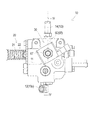
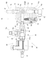
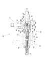
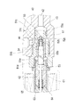
2 リフトシリンダ
10 バルブ装置
11 バルブケース
11p (バルブケース11の)ポンプポート
11t (バルブケース11の)タンクポート
11d (バルブケース11の)シリンダポート
20 方向制御弁
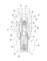
30 電磁ストップバルブ
40 マニフォールド
42 ポンプ・タンク側油路
44 シリンダ側油路
50 チェック弁アセンブリ
60 ソレノイド
Claims (3)
- 作業機昇降用油圧リフトシリンダであって、作業機を上昇させるときに圧油を供給し、作業機を下降させるときに圧油を排出する構成であるものと、該油圧リフトシリンダにおける圧油の供給・排出を制御するための方向制御弁と、該方向制御弁を内装するバルブケースであって、ポンプポート、タンクポート、及びシリンダポートを備えるものと、該バルブケースの該シリンダポートと該油圧リフトシリンダとの間に介装されるマニフォールドと、該マニフォールドに装着される電磁ストップバルブ、より成る作業機の昇降制御装置であって、
該マニフォールドは、内部にポンプ・タンク側油路とシリンダ側油路とを形成し、該ポンプ・タンク側油路の端部が開口する部分を該バルブケースの該シリンダポートに接続して該バルブケースに着脱自在に装着するものであり、該マニフォールドにおける該シリンダ側油路の開口端部を該油圧リフトシリンダに接続可能としていることを特徴とする作業機の昇降制御装置。 - 前記電磁ストップバルブは、そのソレノイドの非励磁状態で、該マニフォールドの該ポンプ・タンク側油路から該シリンダ側油路への油の流れのみを許容するチェック弁として機能し、該ソレノイドの励磁状態で、該マニフォールドの該ポンプ・タンク側油路と該シリンダ側油路との間で双方向に油を流通可能とする開弁状態となることを特徴とする請求項1に記載の作業機の昇降制御装置。
- 前記方向制御弁は、前記油圧リフトシリンダに対して圧油を供給するための上昇位置、該油圧リフトシリンダから圧油を排出するための下降位置、該油圧リフトシリンダにおける圧油の供給・排出を停止するための中立位置のいずれかに設定可能な構成であり、前記電磁ストップバルブの前記ソレノイドは、該方向制御弁を該下降位置に設定したときのみ、励磁されるように該方向制御弁の操作具と連動連係されることを特徴とする請求項2に記載の作業機の昇降制御装置。
Priority Applications (2)
| Application Number | Priority Date | Filing Date | Title |
|---|---|---|---|
| JP2015257021A JP6651101B2 (ja) | 2015-12-28 | 2015-12-28 | 作業機の昇降制御装置 |
| CN201611220310.XA CN107013513B (zh) | 2015-12-28 | 2016-12-26 | 作业机的升降控制装置 |
Applications Claiming Priority (1)
| Application Number | Priority Date | Filing Date | Title |
|---|---|---|---|
| JP2015257021A JP6651101B2 (ja) | 2015-12-28 | 2015-12-28 | 作業機の昇降制御装置 |
Publications (2)
| Publication Number | Publication Date |
|---|---|
| JP2017120109A true JP2017120109A (ja) | 2017-07-06 |
| JP6651101B2 JP6651101B2 (ja) | 2020-02-19 |
Family
ID=59271875
Family Applications (1)
| Application Number | Title | Priority Date | Filing Date |
|---|---|---|---|
| JP2015257021A Active JP6651101B2 (ja) | 2015-12-28 | 2015-12-28 | 作業機の昇降制御装置 |
Country Status (2)
| Country | Link |
|---|---|
| JP (1) | JP6651101B2 (ja) |
| CN (1) | CN107013513B (ja) |
Citations (6)
| Publication number | Priority date | Publication date | Assignee | Title |
|---|---|---|---|---|
| JPS5610309U (ja) * | 1979-07-04 | 1981-01-29 | ||
| JPS58110204U (ja) * | 1982-01-23 | 1983-07-27 | 三菱農機株式会社 | 移動農機の作業機昇降装置 |
| JPH0653802U (ja) * | 1992-12-28 | 1994-07-22 | 株式会社島津製作所 | シリンダ駆動回路 |
| JP2004036750A (ja) * | 2002-07-03 | 2004-02-05 | Aichi Corp | シリンダ作動制御装置 |
| US20050044849A1 (en) * | 2003-08-09 | 2005-03-03 | Deere & Company, A Delaware Corporation | Hydraulic control arrangement for a mobile work machine |
| JP2009156366A (ja) * | 2007-12-27 | 2009-07-16 | Hitachi Constr Mach Co Ltd | 高所作業機の駆動装置 |
Family Cites Families (4)
| Publication number | Priority date | Publication date | Assignee | Title |
|---|---|---|---|---|
| JPH07332309A (ja) * | 1994-06-13 | 1995-12-22 | Ichikawagumi Kk | 油圧装置 |
| DE19604315A1 (de) * | 1996-02-07 | 1997-08-14 | Bosch Gmbh Robert | Elektromagnetisch betätigtes Ventil, insbesondere für hydraulische Bremsanlagen von Kraftfahrzeugen |
| JP5356159B2 (ja) * | 2009-09-02 | 2013-12-04 | 日立建機株式会社 | 油圧作業機の油圧駆動装置 |
| KR102107579B1 (ko) * | 2012-11-07 | 2020-05-07 | 히다찌 겐끼 가부시키가이샤 | 건설 기계의 유압 구동 장치 |
-
2015
- 2015-12-28 JP JP2015257021A patent/JP6651101B2/ja active Active
-
2016
- 2016-12-26 CN CN201611220310.XA patent/CN107013513B/zh active Active
Patent Citations (6)
| Publication number | Priority date | Publication date | Assignee | Title |
|---|---|---|---|---|
| JPS5610309U (ja) * | 1979-07-04 | 1981-01-29 | ||
| JPS58110204U (ja) * | 1982-01-23 | 1983-07-27 | 三菱農機株式会社 | 移動農機の作業機昇降装置 |
| JPH0653802U (ja) * | 1992-12-28 | 1994-07-22 | 株式会社島津製作所 | シリンダ駆動回路 |
| JP2004036750A (ja) * | 2002-07-03 | 2004-02-05 | Aichi Corp | シリンダ作動制御装置 |
| US20050044849A1 (en) * | 2003-08-09 | 2005-03-03 | Deere & Company, A Delaware Corporation | Hydraulic control arrangement for a mobile work machine |
| JP2009156366A (ja) * | 2007-12-27 | 2009-07-16 | Hitachi Constr Mach Co Ltd | 高所作業機の駆動装置 |
Also Published As
| Publication number | Publication date |
|---|---|
| CN107013513A (zh) | 2017-08-04 |
| JP6651101B2 (ja) | 2020-02-19 |
| CN107013513B (zh) | 2021-05-14 |
Similar Documents
| Publication | Publication Date | Title |
|---|---|---|
| KR101859631B1 (ko) | 차동 압력 제어를 갖는 압력 보상형 유압 시스템 | |
| EP2949949A1 (en) | Fluid pressure control device | |
| US7448309B2 (en) | Hydraulic arrangement | |
| JP2012527586A (ja) | 移動式油圧装置、移動式油圧機械およびバルブユニットのための油圧切換機構 | |
| CN102588371A (zh) | 用于操作单作用液压缸的阀控制阀管路 | |
| JP2007239992A (ja) | 複数の圧力リリーフレベルを有する油圧システム | |
| EP3081819B1 (en) | Fluid pressure control device | |
| EP1764339B1 (en) | Hydraulic arrangement for a lifting arm pivotably mounted on a vehicle | |
| EP3470676B1 (en) | Pump device | |
| JP2020063788A (ja) | 降下防止弁装置、ブレード装置および作業機械 | |
| JP2017120109A (ja) | 作業機の昇降制御装置 | |
| GB2580637A (en) | Systems and methods for selective enablement of hydraulic operation | |
| JP6621382B2 (ja) | 作業機の油圧駆動装置 | |
| JP3274305B2 (ja) | 作業車の作業装置用操作構造 | |
| JP3078995B2 (ja) | 作業車の作業装置用操作構造 | |
| EP3545199A1 (en) | Hydraulic valve with switching regeneration circuit | |
| JP2018009595A (ja) | 作業機の油圧駆動装置 | |
| JP3077258B2 (ja) | トラクタ作業機等の昇降用油圧装置 | |
| JP2018031439A (ja) | 作業機の油圧駆動装置 | |
| JP2002061606A (ja) | 油圧シリンダの再生油量コントロール弁 | |
| CN119103233B (zh) | 电液提升阀 | |
| EP2196682A1 (en) | A hydraulic device for controlling an actuator in a work vehicle | |
| JP2008061551A (ja) | 対地作業車両の作業機昇降装置 | |
| JP7771358B2 (ja) | 油圧システム | |
| JP4484610B2 (ja) | 作業車 |
Legal Events
| Date | Code | Title | Description |
|---|---|---|---|
| A621 | Written request for application examination |
Free format text: JAPANESE INTERMEDIATE CODE: A621 Effective date: 20180903 |
|
| A977 | Report on retrieval |
Free format text: JAPANESE INTERMEDIATE CODE: A971007 Effective date: 20190612 |
|
| A131 | Notification of reasons for refusal |
Free format text: JAPANESE INTERMEDIATE CODE: A131 Effective date: 20190625 |
|
| TRDD | Decision of grant or rejection written | ||
| A01 | Written decision to grant a patent or to grant a registration (utility model) |
Free format text: JAPANESE INTERMEDIATE CODE: A01 Effective date: 20191126 |
|
| A61 | First payment of annual fees (during grant procedure) |
Free format text: JAPANESE INTERMEDIATE CODE: A61 Effective date: 20191218 |
|
| R150 | Certificate of patent or registration of utility model |
Ref document number: 6651101 Country of ref document: JP Free format text: JAPANESE INTERMEDIATE CODE: R150 |
|
| R250 | Receipt of annual fees |
Free format text: JAPANESE INTERMEDIATE CODE: R250 |
|
| R250 | Receipt of annual fees |
Free format text: JAPANESE INTERMEDIATE CODE: R250 |
|
| R250 | Receipt of annual fees |
Free format text: JAPANESE INTERMEDIATE CODE: R250 |
|
| R250 | Receipt of annual fees |
Free format text: JAPANESE INTERMEDIATE CODE: R250 |