JP2017122425A - Control device of internal combustion engine with supercharger - Google Patents
Control device of internal combustion engine with supercharger Download PDFInfo
- Publication number
- JP2017122425A JP2017122425A JP2016002928A JP2016002928A JP2017122425A JP 2017122425 A JP2017122425 A JP 2017122425A JP 2016002928 A JP2016002928 A JP 2016002928A JP 2016002928 A JP2016002928 A JP 2016002928A JP 2017122425 A JP2017122425 A JP 2017122425A
- Authority
- JP
- Japan
- Prior art keywords
- compressor
- bypass valve
- turbine
- valve
- supercharger
- Prior art date
- Legal status (The legal status is an assumption and is not a legal conclusion. Google has not performed a legal analysis and makes no representation as to the accuracy of the status listed.)
- Granted
Links
Images
Classifications
-
- F—MECHANICAL ENGINEERING; LIGHTING; HEATING; WEAPONS; BLASTING
- F02—COMBUSTION ENGINES; HOT-GAS OR COMBUSTION-PRODUCT ENGINE PLANTS
- F02B—INTERNAL-COMBUSTION PISTON ENGINES; COMBUSTION ENGINES IN GENERAL
- F02B37/00—Engines characterised by provision of pumps driven at least for part of the time by exhaust
- F02B37/004—Engines characterised by provision of pumps driven at least for part of the time by exhaust with exhaust drives arranged in series
-
- F—MECHANICAL ENGINEERING; LIGHTING; HEATING; WEAPONS; BLASTING
- F02—COMBUSTION ENGINES; HOT-GAS OR COMBUSTION-PRODUCT ENGINE PLANTS
- F02B—INTERNAL-COMBUSTION PISTON ENGINES; COMBUSTION ENGINES IN GENERAL
- F02B27/00—Use of kinetic or wave energy of charge in induction systems, or of combustion residues in exhaust systems, for improving quantity of charge or for increasing removal of combustion residues
- F02B27/02—Use of kinetic or wave energy of charge in induction systems, or of combustion residues in exhaust systems, for improving quantity of charge or for increasing removal of combustion residues the systems having variable, i.e. adjustable, cross-sectional areas, chambers of variable volume, or like variable means
- F02B27/0294—Actuators or controllers therefor; Diagnosis; Calibration
-
- F—MECHANICAL ENGINEERING; LIGHTING; HEATING; WEAPONS; BLASTING
- F02—COMBUSTION ENGINES; HOT-GAS OR COMBUSTION-PRODUCT ENGINE PLANTS
- F02B—INTERNAL-COMBUSTION PISTON ENGINES; COMBUSTION ENGINES IN GENERAL
- F02B29/00—Engines characterised by provision for charging or scavenging not provided for in groups F02B25/00, F02B27/00 or F02B33/00 - F02B39/00; Details thereof
- F02B29/04—Cooling of air intake supply
-
- F—MECHANICAL ENGINEERING; LIGHTING; HEATING; WEAPONS; BLASTING
- F02—COMBUSTION ENGINES; HOT-GAS OR COMBUSTION-PRODUCT ENGINE PLANTS
- F02B—INTERNAL-COMBUSTION PISTON ENGINES; COMBUSTION ENGINES IN GENERAL
- F02B37/00—Engines characterised by provision of pumps driven at least for part of the time by exhaust
- F02B37/013—Engines characterised by provision of pumps driven at least for part of the time by exhaust with exhaust-driven pumps arranged in series
-
- F—MECHANICAL ENGINEERING; LIGHTING; HEATING; WEAPONS; BLASTING
- F02—COMBUSTION ENGINES; HOT-GAS OR COMBUSTION-PRODUCT ENGINE PLANTS
- F02B—INTERNAL-COMBUSTION PISTON ENGINES; COMBUSTION ENGINES IN GENERAL
- F02B37/00—Engines characterised by provision of pumps driven at least for part of the time by exhaust
- F02B37/12—Control of the pumps
- F02B37/16—Control of the pumps by bypassing charging air
- F02B37/162—Control of the pumps by bypassing charging air by bypassing, e.g. partially, intake air from pump inlet to pump outlet
-
- F—MECHANICAL ENGINEERING; LIGHTING; HEATING; WEAPONS; BLASTING
- F02—COMBUSTION ENGINES; HOT-GAS OR COMBUSTION-PRODUCT ENGINE PLANTS
- F02D—CONTROLLING COMBUSTION ENGINES
- F02D41/00—Electrical control of supply of combustible mixture or its constituents
- F02D41/0002—Controlling intake air
- F02D41/0007—Controlling intake air for control of turbo-charged or super-charged engines
-
- F—MECHANICAL ENGINEERING; LIGHTING; HEATING; WEAPONS; BLASTING
- F02—COMBUSTION ENGINES; HOT-GAS OR COMBUSTION-PRODUCT ENGINE PLANTS
- F02D—CONTROLLING COMBUSTION ENGINES
- F02D41/00—Electrical control of supply of combustible mixture or its constituents
- F02D41/22—Safety or indicating devices for abnormal conditions
- F02D41/221—Safety or indicating devices for abnormal conditions relating to the failure of actuators or electrically driven elements
-
- F—MECHANICAL ENGINEERING; LIGHTING; HEATING; WEAPONS; BLASTING
- F02—COMBUSTION ENGINES; HOT-GAS OR COMBUSTION-PRODUCT ENGINE PLANTS
- F02D—CONTROLLING COMBUSTION ENGINES
- F02D2200/00—Input parameters for engine control
- F02D2200/02—Input parameters for engine control the parameters being related to the engine
- F02D2200/04—Engine intake system parameters
- F02D2200/0406—Intake manifold pressure
-
- F—MECHANICAL ENGINEERING; LIGHTING; HEATING; WEAPONS; BLASTING
- F02—COMBUSTION ENGINES; HOT-GAS OR COMBUSTION-PRODUCT ENGINE PLANTS
- F02D—CONTROLLING COMBUSTION ENGINES
- F02D2200/00—Input parameters for engine control
- F02D2200/02—Input parameters for engine control the parameters being related to the engine
- F02D2200/06—Fuel or fuel supply system parameters
- F02D2200/0614—Actual fuel mass or fuel injection amount
-
- F—MECHANICAL ENGINEERING; LIGHTING; HEATING; WEAPONS; BLASTING
- F02—COMBUSTION ENGINES; HOT-GAS OR COMBUSTION-PRODUCT ENGINE PLANTS
- F02D—CONTROLLING COMBUSTION ENGINES
- F02D2200/00—Input parameters for engine control
- F02D2200/02—Input parameters for engine control the parameters being related to the engine
- F02D2200/10—Parameters related to the engine output, e.g. engine torque or engine speed
- F02D2200/101—Engine speed
-
- Y—GENERAL TAGGING OF NEW TECHNOLOGICAL DEVELOPMENTS; GENERAL TAGGING OF CROSS-SECTIONAL TECHNOLOGIES SPANNING OVER SEVERAL SECTIONS OF THE IPC; TECHNICAL SUBJECTS COVERED BY FORMER USPC CROSS-REFERENCE ART COLLECTIONS [XRACs] AND DIGESTS
- Y02—TECHNOLOGIES OR APPLICATIONS FOR MITIGATION OR ADAPTATION AGAINST CLIMATE CHANGE
- Y02T—CLIMATE CHANGE MITIGATION TECHNOLOGIES RELATED TO TRANSPORTATION
- Y02T10/00—Road transport of goods or passengers
- Y02T10/10—Internal combustion engine [ICE] based vehicles
- Y02T10/12—Improving ICE efficiencies
-
- Y—GENERAL TAGGING OF NEW TECHNOLOGICAL DEVELOPMENTS; GENERAL TAGGING OF CROSS-SECTIONAL TECHNOLOGIES SPANNING OVER SEVERAL SECTIONS OF THE IPC; TECHNICAL SUBJECTS COVERED BY FORMER USPC CROSS-REFERENCE ART COLLECTIONS [XRACs] AND DIGESTS
- Y02—TECHNOLOGIES OR APPLICATIONS FOR MITIGATION OR ADAPTATION AGAINST CLIMATE CHANGE
- Y02T—CLIMATE CHANGE MITIGATION TECHNOLOGIES RELATED TO TRANSPORTATION
- Y02T10/00—Road transport of goods or passengers
- Y02T10/10—Internal combustion engine [ICE] based vehicles
- Y02T10/40—Engine management systems
Landscapes
- Engineering & Computer Science (AREA)
- Chemical & Material Sciences (AREA)
- Combustion & Propulsion (AREA)
- Mechanical Engineering (AREA)
- General Engineering & Computer Science (AREA)
- Health & Medical Sciences (AREA)
- Biomedical Technology (AREA)
- Physics & Mathematics (AREA)
- Thermal Sciences (AREA)
- Supercharger (AREA)
Abstract
【課題】インタークーラを循環する冷却水の沸騰を抑制できる過給機付き内燃機関の制御装置を提供する。
【解決手段】直列に配設された第1過給機50と第2過給機60とを有する内燃機関20に適用される制御装置10は、過給圧を制御する過給系制御部11と、インタークーラ71を循環する冷却水の流量を制御する冷却系制御部12と、コンプレッサバイパスバルブ32の開固着を検出することのできるバルブ異常検出部13とを備える。バルブ異常検出部13によってコンプレッサバイパスバルブ32の開固着を検出したとき、冷却系制御部12はポンプ72の駆動量を増大させてインタークーラ71を循環する冷却水の流量を増大させる。
【選択図】図1A control device for an internal combustion engine with a supercharger capable of suppressing boiling of cooling water circulating in an intercooler.
A control device applied to an internal combustion engine having a first supercharger and a second supercharger arranged in series includes a supercharging system control unit that controls a supercharging pressure. And a cooling system control unit 12 that controls the flow rate of the cooling water circulating through the intercooler 71, and a valve abnormality detection unit 13 that can detect open fixation of the compressor bypass valve 32. When the valve abnormality detector 13 detects that the compressor bypass valve 32 is stuck open, the cooling system controller 12 increases the driving amount of the pump 72 to increase the flow rate of the cooling water circulating through the intercooler 71.
[Selection] Figure 1
Description
この発明は、過給機付き内燃機関の制御装置に関するものである。 The present invention relates to a control device for an internal combustion engine with a supercharger.
排気タービン式過給機を二つ備える内燃機関が知られている。例えば、特許文献1に開示されている過給機付き内燃機関では、第1過給機と第2過給機とが直列に配設されている。具体的には、吸気通路には第1過給機の第1コンプレッサが第2過給機の第2コンプレッサよりも上流側に位置するように第1コンプレッサと第2コンプレッサとが直列に配設されており、排気通路には第2過給機の第2タービンが第1過給機の第1タービンよりも上流側に位置するように第1タービンと第2タービンとが直列に配設されている。これにより、第1コンプレッサによって過給した空気を第2コンプレッサによってさらに過給して、燃焼室へ供給することができるようになっている。さらに、この内燃機関では、第2過給機の作動量を制御するために、吸気通路に第2コンプレッサを迂回させて空気を流すコンプレッサバイパス通路を設けるとともに、排気通路に第2タービンを迂回させて排気を流すタービンバイパス通路を設けている。そして、コンプレッサバイパス通路にコンプレッサバイパスバルブを、タービンバイパス通路にタービンバイパスバルブを設けている。 An internal combustion engine having two exhaust turbine superchargers is known. For example, in an internal combustion engine with a supercharger disclosed in Patent Document 1, a first supercharger and a second supercharger are arranged in series. Specifically, the first compressor and the second compressor are arranged in series in the intake passage so that the first compressor of the first supercharger is located upstream of the second compressor of the second supercharger. The first turbine and the second turbine are arranged in series in the exhaust passage so that the second turbine of the second supercharger is located upstream of the first turbine of the first supercharger. ing. Thereby, the air supercharged by the first compressor can be further supercharged by the second compressor and supplied to the combustion chamber. Further, in this internal combustion engine, in order to control the operation amount of the second supercharger, the intake passage is provided with a compressor bypass passage that bypasses the second compressor and flows air, and the second turbine is bypassed in the exhaust passage. A turbine bypass passage is provided for exhaust flow. A compressor bypass valve is provided in the compressor bypass passage, and a turbine bypass valve is provided in the turbine bypass passage.
ところで、特許文献1に開示されている過給機付き内燃機関において、コンプレッサバイパスバルブに異常が生じて当該バルブの開度を小さくすることができなくなった場合、コンプレッサバイパス通路を通じて第2コンプレッサよりも上流側の吸気通路と第2コンプレッサよりも下流側の吸気通路との連通が維持された状態となる。このとき、コンプレッサバイパスバルブが正常に動作している場合と同様にタービンバイパスバルブの制御を行うと、吸気通路における第2コンプレッサよりも下流側の部分と上流側の部分との圧力差に基づいて空気が逆流する虞がある。つまり、コンプレッサバイパス通路を閉塞できない状態において、タービンバイパスバルブの開度が小さくなるように制御されて第2過給機による過給が行われることがある。この過給によって生じる吸気通路内の圧力差に伴って、相対的に高圧となる第2コンプレッサよりも下流側の部分から相対的に低圧となる第2コンプレッサよりも上流側の部分へと、コンプレッサバイパス通路を介して吸気の一部が還流する虞がある。こうした還流が発生すると、第2コンプレッサよりも上流側の部分へ逆流した空気が再び第2コンプレッサによって過給される。そして、過給の繰り返しによって高温の空気が還流することになり、吸気通路の温度が次第に上昇して過度に高温となる。また、過給機付き内燃機関においては、過給された空気を冷却するためのインタークーラが、吸気通路における過給機よりも下流側の部分に設けられている。つまり、過度に高温となった空気がインタークーラに流入する虞があり、インタークーラを循環している冷却水が過熱されて沸騰する虞があった。 By the way, in the internal combustion engine with a supercharger disclosed in Patent Document 1, when an abnormality occurs in the compressor bypass valve and the opening degree of the valve cannot be reduced, the compressor bypass passage is more than the second compressor. The communication between the upstream intake passage and the intake passage downstream of the second compressor is maintained. At this time, if the turbine bypass valve is controlled in the same manner as when the compressor bypass valve is operating normally, it is based on the pressure difference between the downstream portion and the upstream portion of the second compressor in the intake passage. Air may flow backward. In other words, in a state where the compressor bypass passage cannot be closed, supercharging by the second supercharger may be performed by controlling the opening of the turbine bypass valve to be small. In accordance with the pressure difference in the intake passage caused by this supercharging, the compressor moves from a portion downstream of the second compressor having a relatively high pressure to a portion upstream of the second compressor having a relatively low pressure. There is a possibility that a part of the intake air may recirculate through the bypass passage. When such reflux occurs, the air that has flowed back to the upstream side of the second compressor is again supercharged by the second compressor. Then, the high-temperature air recirculates due to repeated supercharging, and the temperature of the intake passage gradually rises and becomes excessively high. Moreover, in the internal combustion engine with a supercharger, an intercooler for cooling the supercharged air is provided in a portion on the downstream side of the supercharger in the intake passage. That is, there is a possibility that the air that has become excessively hot flows into the intercooler, and the cooling water circulating through the intercooler may be overheated and boiled.
本発明の目的は、インタークーラを循環する冷却水の沸騰を抑制できる過給機付き内燃機関の制御装置を提供することにある。 The objective of this invention is providing the control apparatus of the internal combustion engine with a supercharger which can suppress the boiling of the cooling water which circulates through an intercooler.
以下、上記課題を解決するための手段及びその作用効果について記載する。
上記課題を解決するための過給機付き内燃機関の制御装置は、吸気通路に上流側から順に第1コンプレッサと第2コンプレッサとが設けられているとともに、排気通路に上流側から順に第2タービンと第1タービンとが設けられており、前記第1コンプレッサ及び前記第1タービンを有する第1過給機と、前記第2コンプレッサ及び前記第2タービンを有する第2過給機と、が直列に配設された過給系と、前記吸気通路における前記第2コンプレッサよりも下流側に設けられたインタークーラと、同インタークーラを流れる冷却水の経路に設けられていて同経路内で冷却水を循環させる電動式のポンプと、を備える冷却系と、を有しており、前記過給系において、前記第2コンプレッサを迂回させて空気を流すコンプレッサバイパス通路及び同コンプレッサバイパス通路を開閉するコンプレッサバイパスバルブが前記吸気通路に設けられているとともに、前記第2タービンを迂回させて排気を流すタービンバイパス通路及び同タービンバイパス通路を開閉するタービンバイパスバルブが前記排気通路に設けられている内燃機関に適用され、前記コンプレッサバイパスバルブと前記タービンバイパスバルブとを制御する過給系制御部と、前記ポンプを制御する冷却系制御部と、を備える過給機付き内燃機関の制御装置であって、前記コンプレッサバイパスバルブの開固着を検出することができるバルブ異常検出部を備え、前記バルブ異常検出部によって前記コンプレッサバイパスバルブの開固着が検出されたとき、前記冷却系制御部が前記ポンプの駆動量を、前記コンプレッサバイパスバルブの開固着が検出されていないときよりも増大させて前記インタークーラを循環する冷却水の流量を増大させることをその要旨とする。
Hereinafter, means for solving the above-described problems and the effects thereof will be described.
A control device for an internal combustion engine with a supercharger for solving the above-mentioned problems is provided with a first compressor and a second compressor in order from the upstream side in the intake passage, and a second turbine in order from the upstream side in the exhaust passage. And a first turbine, and a first supercharger having the first compressor and the first turbine and a second supercharger having the second compressor and the second turbine are connected in series. A supercharging system that is disposed; an intercooler that is provided downstream of the second compressor in the intake passage; and a cooling water path that flows through the intercooler. A compressor bypass passage for flowing air by bypassing the second compressor in the supercharging system, and a cooling system comprising an electric pump for circulation A compressor bypass valve that opens and closes the compressor bypass passage is provided in the intake passage, and a turbine bypass passage that bypasses the second turbine and flows exhaust gas and a turbine bypass valve that opens and closes the turbine bypass passage are provided in the exhaust passage. An internal combustion engine with a supercharger, which is applied to an internal combustion engine provided, and includes a supercharging system control unit that controls the compressor bypass valve and the turbine bypass valve, and a cooling system control unit that controls the pump. A control device comprising a valve abnormality detection unit capable of detecting open adhering of the compressor bypass valve; and when the valve adhering detection of the compressor bypass valve is detected by the valve abnormality detecting unit, the cooling system control unit The drive amount of the pump, the compressor bypass Open sticking of the valve and its gist at increasing the flow rate of the cooling water circulating the intercooler is increased than when it is not detected.
上記構成によれば、コンプレッサバイパスバルブの開固着が検出されたときにはインタークーラを循環する冷却水の流量が増大される。そのため、コンプレッサバイパスバルブの開固着に伴って空気の逆流が発生し、コンプレッサバイパス通路を介して空気が還流することによって過給が繰り返されて過度に高温になった空気と冷却水との熱交換がインタークーラにて行われることになっても、冷却水が速やかにインタークーラを通過するようになる。したがって、冷却水の昇温を抑制することができる。すなわち、インタークーラ内の冷却水が沸騰することを抑制することができる。 According to the above configuration, the flow rate of the cooling water circulating through the intercooler is increased when the open adhesion of the compressor bypass valve is detected. For this reason, backflow of air occurs with the open fixing of the compressor bypass valve, and air is recirculated through the compressor bypass passage. However, the cooling water immediately passes through the intercooler. Therefore, the temperature rise of the cooling water can be suppressed. That is, it is possible to suppress boiling of the cooling water in the intercooler.
上記過給機付き内燃機関の制御装置の一例では、前記過給系制御部は、前記バルブ異常検出部によって前記コンプレッサバイパスバルブの開固着が検出されたときに、前記タービンバイパスバルブを全開にする。 In an example of the control device for an internal combustion engine with a supercharger, the supercharging system control unit fully opens the turbine bypass valve when the valve abnormality detection unit detects that the compressor bypass valve is stuck open. .
上記構成によれば、コンプレッサバイパスバルブの開固着が検出されたときにはタービンバイパスバルブが全開になる。つまり、タービンバイパス通路を通過する排気の流量が多くなるため、第2タービンの回転が抑制され、第2コンプレッサによる過給が抑制される。そのため、コンプレッサバイパスバルブが開固着した際に過給が繰り返されることに伴って空気が過度に高温になることを抑制することができる。すなわち、インタークーラに流入する空気が過度に高温になることが抑制され、インタークーラ内の冷却水が沸騰することをより抑制することができる。 According to the above configuration, the turbine bypass valve is fully opened when it is detected that the compressor bypass valve is stuck open. That is, since the flow rate of the exhaust gas that passes through the turbine bypass passage increases, the rotation of the second turbine is suppressed, and the supercharging by the second compressor is suppressed. Therefore, it is possible to suppress the air from becoming excessively high due to repeated supercharging when the compressor bypass valve is stuck open. That is, it is possible to suppress the air flowing into the intercooler from becoming excessively high in temperature and to further suppress boiling of the cooling water in the intercooler.
上記過給機付き内燃機関の制御装置の一例では、前記過給系制御部は、前記コンプレッサバイパスバルブの目標開度及び前記タービンバイパスバルブの目標開度を算出し、算出した目標開度に合わせて前記コンプレッサバイパスバルブ及び前記タービンバイパスバルブを駆動するものであり、前記バルブ異常検出部は、前記吸気通路における前記コンプレッサバイパスバルブよりも下流側における吸気圧を検出する吸気圧センサの検出値と前記過給系制御部が算出する前記コンプレッサバイパスバルブの目標開度とを取得して、取得した検出値と目標開度とに基づいて前記コンプレッサバイパスバルブの開固着を検出する。 In an example of the control device for an internal combustion engine with a supercharger, the supercharging system control unit calculates a target opening of the compressor bypass valve and a target opening of the turbine bypass valve, and matches the calculated target opening. The compressor bypass valve and the turbine bypass valve are driven, and the valve abnormality detection unit detects the intake pressure sensor that detects an intake pressure downstream of the compressor bypass valve in the intake passage, and the detected value A target opening of the compressor bypass valve calculated by the supercharging system control unit is acquired, and open adhering of the compressor bypass valve is detected based on the acquired detected value and the target opening.
コンプレッサバイパスバルブの開度が目標開度と等しい値に制御されている場合に吸気圧センサによって検出される吸気圧の値は、目標開度に基づいて推定することができる。そのため、目標開度から推定される吸気圧と、実際の吸気圧とを比較することによって、コンプレッサバイパスバルブが目標開度に合わせて制御されているか否かを検出することができる。すなわち上記構成のように目標開度と吸気圧センサの検出値とを用いれば、コンプレッサバイパスバルブの開固着を検出することができる。 When the opening of the compressor bypass valve is controlled to be equal to the target opening, the value of the intake pressure detected by the intake pressure sensor can be estimated based on the target opening. Therefore, by comparing the intake pressure estimated from the target opening and the actual intake pressure, it is possible to detect whether or not the compressor bypass valve is controlled in accordance with the target opening. That is, if the target opening and the detected value of the intake pressure sensor are used as in the above configuration, it is possible to detect the open fixation of the compressor bypass valve.
(第1の実施形態)
以下、過給機付き内燃機関の制御装置の第1の実施形態である制御装置10について、図1〜図4を参照して説明する。
(First embodiment)
Hereinafter, the
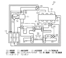
図1を用いて、制御装置10の制御対象である内燃機関20について説明する。内燃機関20は、複数の気筒を備えている。内燃機関20は、吸気通路30から空気を気筒に導入する。また、内燃機関20は、燃料噴射弁から燃料を噴射し、気筒内にて空気及び燃料を燃焼させる。内燃機関20は、排気通路40から排気を排出する。排気通路40の途中には、排気を利用してタービンを回転させる第1過給機50と、第2過給機60と、が設けられている。
An
第1過給機50は、第1タービン52と、第1タービン52の回転に伴って駆動される第1コンプレッサ51とを備えている。第2過給機60は、第2タービン62と、第2タービン62の回転に伴って駆動される第2コンプレッサ61とを備えている。第1過給機50は、第2過給機60よりも大容量の過給機である。また、第1コンプレッサ51は、吸気通路30において第2コンプレッサ61よりも上流側に配設されている。そして、第1タービン52は、排気通路40において第2タービン62よりも下流側に配設されている。すなわち、内燃機関20では第1過給機50と第2過給機60とが直列に配設されている。
The
吸気通路30には、第2コンプレッサ61を迂回するコンプレッサバイパス通路31が設けられている。さらに、吸気通路30には、コンプレッサバイパス通路31を開閉するコンプレッサバイパスバルブ32が設けられている。コンプレッサバイパスバルブ32は、電動アクチュエータによって開度が調節される。コンプレッサバイパスバルブ32が全閉しているときには、第1コンプレッサ51を通過した空気が第2コンプレッサ61に全て流入する。一方、コンプレッサバイパスバルブ32が開いていると、第1コンプレッサ51を通過した空気がコンプレッサバイパス通路31を通過して吸気通路30における第2コンプレッサ61よりも下流側の部分に流入する。すなわち、コンプレッサバイパスバルブ32の開度を調節することで、第2コンプレッサ61に流入する空気の流量と、コンプレッサバイパス通路31を通過して第2コンプレッサ61を迂回する空気の流量との割合を調節することができる。
The
吸気通路30における第2コンプレッサ61よりも下流側には、吸気通路30内の空気を冷却するインタークーラ71が設けられている。インタークーラ71には冷却水通路74が接続されており、冷却水通路74によってインタークーラ71に冷却水を循環させる経路が形成されている。冷却水通路74には、インタークーラ71に冷却水を導入する電動式のポンプ72が設けられている。さらに、冷却水通路74には、インタークーラ71を通過した冷却水を冷却するラジエータ73も設けられている。内燃機関20では、これらのインタークーラ71、ポンプ72、ラジエータ73及び冷却水通路74によって、吸気の冷却系が構成されている。
An
内燃機関20のシリンダヘッドには、吸気通路30内の空気を分配して各気筒に導入するインテークマニホールド34が接続されている。吸気通路30におけるインテークマニホールド34とインタークーラ71との間には、スロットルバルブ33が設けられている。
An
また、内燃機関20のシリンダヘッドには、各気筒から排出した排気を集合させるエキゾーストマニホールド41が接続されている。エキゾーストマニホールド41を介して集合した排気が排気通路40を通じて排出される。
Further, an
排気通路40におけるエキゾーストマニホールド41よりも下流側には、第2過給機60の第2タービン62が配設されている。また、排気通路40には、第2タービン62を迂回するタービンバイパス通路42が設けられている。さらに、排気通路40には、タービンバイパス通路42を開閉するタービンバイパスバルブ43も設けられている。タービンバイパスバルブ43は、電動アクチュエータによって開度が調節される。タービンバイパスバルブ43が全閉しているときには、エキゾーストマニホールド41を通過した排気が第2タービン62に全て流入する。一方、タービンバイパスバルブ43が開いていると、エキゾーストマニホールド41を通過した排気がタービンバイパス通路42を通過して排気通路40における第2タービン62よりも下流側の部分に流入する。すなわち、タービンバイパスバルブ43の開度を調節することで、第2タービン62に流入する排気の流量と、タービンバイパス通路42を通過して第2タービン62を迂回する排気の流量との割合を調節することができる。
A
排気通路40において第2タービン62よりも下流側には、第1過給機50の第1タービン52が配設されている。また、排気通路40には、第1タービン52を迂回する排気バイパス通路44が設けられている。さらに排気通路40には、排気バイパス通路44を開閉する排気バイパスバルブ45が設けられている。排気バイパスバルブ45は電動アクチュエータによって開閉が制御される。排気バイパスバルブ45が全閉しているときには、第1タービン52よりも上流側から流れてきた排気が第1タービン52に全て流入する。一方、排気バイパスバルブ45が開いているときには、排気通路40における第1タービン52よりも上流側から流れてきた排気が、排気バイパス通路44を通過して排気通路40における第1タービン52よりも下流側の部分に流入する。すなわち、排気バイパスバルブ45の開度を調節することで、第1タービン52に流入する排気の流量と、排気バイパス通路44を通過して第1タービン52を迂回する排気の流量との割合を調節することができる。
A
内燃機関20では、上記説明した第1過給機50及び第2過給機60、コンプレッサバイパス通路31及びコンプレッサバイパスバルブ32、タービンバイパス通路42及びタービンバイパスバルブ43、並びに排気バイパス通路44及び排気バイパスバルブ45によって、吸気を過給する過給系が構成されている。
In the
また、内燃機関20は、内燃機関20の運転状態を検出する各種センサを備えている。具体的には、スロットルバルブ33の開度を検出するスロットルセンサ81、内燃機関20の出力軸の回転数を検出する回転数センサ82、吸気通路30におけるインタークーラ71とスロットルバルブ33との間の部分に配設されている吸気圧センサ83、インタークーラ71を通過した空気の温度を検出する吸気温度センサ84を備えている。スロットルセンサ81、回転数センサ82、吸気圧センサ83、吸気温度センサ84等の各種センサは、制御装置10と接続されている。各種センサの検出値は制御装置10に入力される。
The
制御装置10は、内燃機関20の運転状態に基づいて燃料噴射量Qを算出するとともに、燃料噴射量Qに基づく燃料噴射を実行するように内燃機関20を制御する。また、制御装置10は、内燃機関20の運転状態に基づいてスロットルバルブ33の開度を制御する。また、制御装置10は、第1過給機50と第2過給機60の駆動によって得られる過給圧を制御する機能を有する過給系制御部11を備えている。また、制御装置10は、ポンプ72の駆動を制御することでインタークーラ71を循環する冷却水の流量を変更する機能を有する冷却系制御部12を備えている。また、制御装置10は、コンプレッサバイパスバルブ32、タービンバイパスバルブ43、排気バイパスバルブ45等の異常を検出する機能を有するバルブ異常検出部13を備えている。
The
次に、制御装置10の過給系制御部11が行う過給系の基本制御について、図1及び図2を用いて説明する。
過給系制御部11は、内燃機関20の運転状態に応じて第1過給機50と第2過給機60の作動状態を切り換えることで過給圧を制御する機能を有する。具体的には、燃料噴射量Qと回転数センサ82によって検出される機関回転数NEとに基づいて、第1過給機50と第2過給機60とによって得る目標過給圧を設定する。当該目標過給圧が得られるように、コンプレッサバイパスバルブ32、タービンバイパスバルブ43、排気バイパスバルブ45の目標開度を算出する。各バルブ32,43,45の開度が目標開度となるように、各バルブ32,43,45について電動アクチュエータの駆動を制御する。つまり、各バルブ32,43,45を制御することで第1過給機50及び第2過給機60の作動状態を切り換える。
Next, basic control of the supercharging system performed by the supercharging
The supercharging
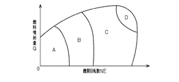
図2に示すように、機関回転数NE及び燃料噴射量Qに基づく内燃機関20の運転状態と、第1過給機50及び第2過給機60の作動状態と、の関係が予め制御装置10に記憶されている。過給系制御部11は、当該関係に基づいて運転状態に応じた過給系の制御を行う。内燃機関20の運転状態は、図2に示す領域A、領域B、領域C、領域Dに区画されており、過給系制御部11は各領域に応じて以下に示す第1〜第4過給態様を切り換える基本制御を行う。
As shown in FIG. 2, the relationship between the operating state of the
(第1過給態様)
内燃機関20の運転状態が、領域Aにあるとき、過給系制御部11は第1過給態様に基づく過給系の制御を行う。第1過給態様では、コンプレッサバイパスバルブ32、タービンバイパスバルブ43、排気バイパスバルブ45のすべてを全閉する。すなわち、第1過給機50及び第2過給機60によって過給が得られるように制御を行う。
(First supercharging mode)
When the operating state of the
(第2過給態様)
内燃機関20の運転状態が、領域Bにあるとき、過給系制御部11は第2過給態様に基づく過給系の制御を行う。第2過給態様では、タービンバイパスバルブ43の開度を調節する。なお、コンプレッサバイパスバルブ32と排気バイパスバルブ45は全閉する。すなわち、第2タービン62に流入する排気の量を調節することで、第2タービン62の回転量を調節する。つまり、第2過給機60の作動量を制御しつつ、第1過給機50及び第2過給機60によって過給が得られるように制御を行う。
(Second supercharging mode)
When the operating state of the
(第3過給態様)
内燃機関20の運転状態が、領域Cにあるとき、過給系制御部11は第3過給態様に基づく過給系の制御を行う。第3過給態様では、タービンバイパスバルブ43を全開にする。さらに、コンプレッサバイパスバルブ32を全開にする。なお、排気バイパスバルブ45は全閉する。すなわち、排気が第2タービン62を迂回するようにするとともに、空気が第2コンプレッサ61を迂回するようにする。つまり、第2過給機60の動作を止めて、第1過給機50のみによる過給を行う。
(Third supercharging mode)
When the operating state of the
(第4過給態様)
内燃機関20の運転状態が、領域Dにあるとき、過給系制御部11は第4過給態様に基づく過給系の制御を行う。第4過給態様では、タービンバイパスバルブ43及びコンプレッサバイパスバルブ32を全開とする。さらに、排気バイパスバルブ45の開度を開き側に制御する。すなわち、排気が第1タービン52を迂回するようにする。
(Fourth supercharging mode)
When the operating state of the
次に、制御装置10の冷却系制御部12が行う冷却系の基本制御について説明する。
冷却系制御部12は、インタークーラ71を通過した空気の温度を吸気温度センサ84の検出値から取得し、ポンプ72を駆動する基本デューティ比を算出する。そして、算出した基本デューティ比に基づいてポンプ72を駆動することでインタークーラ71を循環する冷却水の流量を変更する。なお、冷却系制御部12は、吸気温度センサ84によって検出される吸気温度が高いほど基本デューティ比を大きく算出してポンプ72によってインタークーラ71へ送り込まれる冷却水の流量を増大させる。
Next, basic control of the cooling system performed by the cooling
The cooling
次に、図3を用いて、バルブ異常検出部13について説明する。
バルブ異常検出部13は、図3に示すバルブ異常判定処理を行う。バルブ異常判定処理では、コンプレッサバイパスバルブ32、タービンバイパスバルブ43、排気バイパスバルブ45のいずれかのバルブに異常があるか否かを判定する。
Next, the valve
The
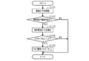
図3に示すバルブ異常判定処理は、所定周期毎に繰り返し実行されるルーチンである。バルブ異常検出部13はバルブ異常判定処理を開始すると、まず、ステップS101において、吸気圧センサ83の検出値である吸気圧PMを取得する。
The valve abnormality determination process shown in FIG. 3 is a routine that is repeatedly executed at predetermined intervals. When the valve
次に、バルブ異常検出部13はステップS102において、回転数センサ82の検出値である機関回転数NEを取得し、機関回転数NEと燃料噴射量Qとに基づいて異常判定可能条件が成立しているか否かを判定する。
Next, in step S102, the valve
ここで異常判定可能条件とは、内燃機関20の運転状態がバルブの異常を検出することのできる状態であるか否かを判定するための条件であり、機関回転数NEと燃料噴射量Qとに基づいて予め設定されている。ここでは、上記説明した過給系の制御態様が第1過給態様であるときに異常判定可能条件が成立していると判定するようにしている。すなわち、機関回転数NEが小さい、つまり内燃機関20が低回転であり、且つ燃料噴射量Qが少なく設定されている所定の運転領域にあるときに異常判定可能条件が成立するようにされている。したがって、内燃機関20の運転状態が変化しにくい状態でバルブ異常判定処理を実行することができるように構成している。
Here, the abnormality determination possible condition is a condition for determining whether or not the operating state of the
こうした異常判定可能条件が成立していない場合(S102:NO)、バルブ異常検出部13は本ルーチンを終了する。一方、異常判定可能条件が成立している場合(S102:YES)、ステップS103の処理が行われ、バルブ異常検出部13は定常吸気圧PDを読み込む。定常吸気圧PDとは、内燃機関20の運転状態に応じて推定される吸気圧として制御装置10に予め記憶されている値である。定常吸気圧PDは、コンプレッサバイパスバルブ32の目標開度、タービンバイパスバルブ43の目標開度、排気バイパスバルブ45の目標開度、機関回転数NE、燃料噴射量Q等の運転状態に基づいて推定することができる。第1過給態様においては、各バルブ32,43,45はすべて全閉であるため、ここでは定常吸気圧PDは、各バルブ32,43,45が全閉になっていることを前提にして推定される吸気圧である。
When such an abnormality determination possible condition is not satisfied (S102: NO), the valve
続いて、バルブ異常検出部13はステップS104に処理を進め、吸気圧PMと定常吸気圧PDとの差の絶対値が所定値αよりも小さいか否かを判定する。例えば、吸気圧PMと定常吸気圧PDとの差の絶対値が所定値α以上であれば、吸気圧PMと定常吸気圧PDとの乖離は所定量以上であると判定することができる。
Subsequently, the valve
吸気圧PMと定常吸気圧PDとの差の絶対値が所定値α以上である場合(S104:NO)、バルブ異常検出部13は本ルーチンを終了する。一方、吸気圧PMと定常吸気圧PDとの差の絶対値が所定値αよりも小さい場合(S104:YES)、バルブ異常検出部13はステップS105へと処理を進め、バルブ異常フラグを「オン」にする。そして、本ルーチンが終了される。
If the absolute value of the difference between the intake pressure PM and the steady intake pressure PD is greater than or equal to the predetermined value α (S104: NO), the valve
以上説明したバルブ異常判定処理によって、バルブ異常フラグが「オン」にされるといずれかのバルブに異常が生じていると判定することができる。いずれかのバルブに異常が生じているということは、コンプレッサバイパスバルブ32が開固着している虞がある。したがって、バルブ異常検出部13が行うバルブ異常判定処理によってバルブ異常フラグが「オン」にされた場合には、それに基づいてコンプレッサバイパスバルブ32が開固着していることを検出することができる。
By the valve abnormality determination process described above, it can be determined that an abnormality has occurred in any of the valves when the valve abnormality flag is turned “ON”. If any one of the valves is abnormal, the
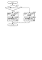
次に、図4を用いて、冷却系の制御について説明する。当該制御は、制御装置10によって行われる。
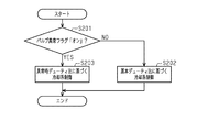
この制御は、所定周期毎に繰り返し実行されるルーチンである。まず、ステップS201において、制御装置10は、バルブ異常フラグが「オン」であるか否かを判定する。バルブ異常フラグが「オン」にされていない場合(S201:NO)、次にステップS202の処理が行われる。ステップS202では、制御装置10が冷却系制御部12に対して、冷却系の基本制御を行う指令を出す。すなわち基本デューティ比に基づいて冷却系の制御を行う指令を出す。冷却系制御部12は、制御装置10からの指令に基づいて基本デューティ比を算出するとともに、基本デューティ比を用いてポンプ72を駆動する。そして、本ルーチンは終了される。
Next, the control of the cooling system will be described with reference to FIG. The control is performed by the
This control is a routine that is repeatedly executed at predetermined intervals. First, in step S201, the
一方、バルブ異常フラグが「オン」である場合(S201:YES)、ステップS203の処理が行われる。ステップS203では、制御装置10が冷却系制御部12に対して、異常時デューティ比に基づいて冷却系の制御を行う指令を出す。冷却系制御部12は、制御装置10からの指令に基づいて異常時デューティ比を算出するとともに、異常時デューティ比を用いてポンプ72を駆動する。なお、このとき冷却系制御部12が冷却系の基本制御を行っている場合には、基本制御を終了して異常時デューティ比の算出を開始する。そして、本ルーチンは終了される。
On the other hand, when the valve abnormality flag is “ON” (S201: YES), the process of step S203 is performed. In step S203, the
ここで、冷却系制御部12が算出する異常時デューティ比とは、インタークーラ71を循環する冷却水の流量が規定流量となるようにポンプ72を駆動するデューティ比である。規定流量は、インタークーラ71を循環する冷却水の流量が規定流量であれば当該冷却水の沸騰を抑制できるように予め行う実験などの結果をもとに設定されている。また、規定流量は、基本デューティ比に基づいてポンプ72が駆動されたときに循環する流量よりも多くなるように設定されている。
Here, the abnormal duty ratio calculated by the cooling
次に、第1の実施形態にかかる制御装置10による作用について説明する。
バルブ異常フラグが「オン」にされていないときには、図4を参照して説明したルーチンを通じてステップS202の処理が行われる。つまり、制御装置10は冷却系制御部12に対して、基本デューティ比に基づいて冷却系の制御を行う指令を出す。したがって、冷却系制御部12は冷却系の基本制御を継続する。
Next, the effect | action by the
When the valve abnormality flag is not “ON”, the process of step S202 is performed through the routine described with reference to FIG. That is, the
一方、バルブ異常フラグが「オン」にされているとき、つまりコンプレッサバイパスバルブ32の開固着が検出されたときには、図4を参照して説明したルーチンを通じてステップS203の処理が行われる。つまり、制御装置10は冷却系制御部12に対して、異常時デューティ比に基づいて冷却系の制御を行う指令を出す。したがって、冷却系制御部12によってポンプ72が異常時デューティ比に基づいて駆動される。
On the other hand, when the valve abnormality flag is set to “ON”, that is, when open fixation of the
以上のように、制御装置10によれば、バルブ異常検出部13によってコンプレッサバイパスバルブ32の開固着が検出されたときには、異常時デューティ比に基づいてポンプ72が駆動されるため、インタークーラ71を循環する冷却水の流量が規定流量となる。換言すれば、コンプレッサバイパスバルブ32の開固着が検出されたときには、冷却系の基本制御と比してポンプ72の駆動量が増大される。こうしてコンプレッサバイパスバルブ32の開固着が検出されていないときよりもポンプ72の駆動量が増大されることによって、インタークーラ71を循環する冷却水の流量が増大される。
As described above, according to the
以上説明した第1の実施形態によれば、以下の効果が得られるようになる。
(1)コンプレッサバイパスバルブ32が開固着し、過度に高温になった空気と冷却水との熱交換がインタークーラ71にて行われることになっても、冷却水が速やかにインタークーラ71を通過するようになる。そのため、冷却水の昇温を抑制することができる。すなわち、インタークーラ71内の冷却水が沸騰することを抑制することができる。
According to the first embodiment described above, the following effects can be obtained.
(1) Even if the
(第2の実施形態)
以下、過給機付き内燃機関の制御装置の第2の実施形態について説明する。第2の実施形態は、図4を参照して説明したルーチンに代わり図5に示すルーチンに従って冷却系及び過給系の制御を行う点で第1の実施形態と異なる。第1の実施形態と共通の構成については同一の符号を付し詳細な説明を適宜省略する。
(Second Embodiment)
Hereinafter, a second embodiment of the control device for an internal combustion engine with a supercharger will be described. The second embodiment differs from the first embodiment in that the cooling system and the supercharging system are controlled according to the routine shown in FIG. 5 instead of the routine described with reference to FIG. The components common to the first embodiment are denoted by the same reference numerals, and detailed description thereof is omitted as appropriate.
図5に示すルーチンも図4を参照して説明したルーチンと同様に、制御装置10が所定周期毎に繰り返し実行する。
図5に示すように、このルーチンにおいてはステップS202の処理に続いてステップS204の処理を実行するようにしている。ステップS204の処理では、制御装置10が過給系制御部11に対して、基本目標開度を用いてタービンバイパスバルブ43を制御する指令を出す。ここで、基本目標開度とは、過給系の基本制御によって算出されるタービンバイパスバルブ43の目標開度である。過給系制御部11は、制御装置10からの指令に基づいて、機関回転数NE及び燃料噴射量Qに基づいて基本目標開度を算出し、基本目標開度を用いてタービンバイパスバルブ43の開度を制御する。そして、本ルーチンは終了される。なお、過給系制御部11は、基本目標開度の算出に続いて、コンプレッサバイパスバルブ32の目標開度と、排気バイパスバルブ45の目標開度とを算出し、過給系の基本制御に基づいた制御を行う。すなわち、このルーチンにおいては、バルブ異常フラグが「オン」にされていない場合(S201:NO)、ステップS202を通じて冷却系制御部12によって基本デューティ比に基づく冷却系の制御が行われる。そして、それに加えて、基本目標開度を用いてタービンバイパスバルブ43の開度が制御される。そして本ルーチンは終了される。
Similarly to the routine described with reference to FIG. 4, the
As shown in FIG. 5, in this routine, the process of step S204 is executed following the process of step S202. In the process of step S204, the
一方、バルブ異常フラグが「オン」である場合(S201:YES)には、ステップS203の処理に続いてステップS205の処理を実行するようにしている。
ステップS205の処理では、制御装置10が過給系制御部11に、異常時目標開度を用いてタービンバイパスバルブ43を制御する指令を出す。ここでは過給系制御部11は制御装置10からの指令に基づいて、タービンバイパスバルブ43を全開にする開度を異常時目標開度として設定する。さらに過給系制御部11は、異常時目標開度に基づいてタービンバイパスバルブ43の制御を行う。すなわち、このルーチンにおいては、バルブ異常フラグが「オン」にされている場合(S201:YES)、ステップS203を通じて冷却系制御部12によって異常時デューティ比に基づく冷却系の制御が行われる。そして、それに加えて、異常時目標開度を用いてタービンバイパスバルブ43の開度が制御される。なお、このとき過給系制御部11は、過給系の基本制御に基づいて排気バイパスバルブ45の制御を行う。そして、本ルーチンは終了される。
On the other hand, when the valve abnormality flag is “ON” (S201: YES), the process of step S205 is executed following the process of step S203.
In the process of step S205, the
次に、第2の実施形態にかかる制御装置10による作用について説明する。
バルブ異常フラグが「オン」にされていないときには、図5を参照して説明したルーチンを通じてステップS202の処理に続いてステップS204の処理が行われ、制御装置10は過給系制御部11に対して、基本目標開度を用いてタービンバイパスバルブ43を制御する指令が出される。したがって、過給系制御部11は過給系の基本制御を継続する。
Next, the operation of the
When the valve abnormality flag is not “ON”, the process of step S204 is performed subsequent to the process of step S202 through the routine described with reference to FIG. Thus, a command for controlling the
一方、バルブ異常フラグが「オン」にされているとき、つまりコンプレッサバイパスバルブ32の開固着が検出されたときには、図5を参照して説明したルーチンを通じてステップS203の処理に続いてステップS205の処理が行われる。すなわち、冷却系制御部12によってインタークーラ71を循環する冷却水の流量が増大されるとともに、過給系制御部11によってタービンバイパスバルブ43が全開に制御される。タービンバイパスバルブ43の開度が全開にされると、第2タービン62の回転が抑制される。すなわち、インタークーラ71を循環する冷却水の流量が増大されることに加えて、第2コンプレッサ61による過給が抑制される。
On the other hand, when the valve abnormality flag is “ON”, that is, when open fixation of the
以上説明した第2の実施形態によれば、第1の実施形態における(1)の効果と同様の効果に加え、以下の効果が得られるようになる。
(2)コンプレッサバイパスバルブ32の開固着が検出されたときには第2コンプレッサ61による過給が抑制される。そのため、コンプレッサバイパス通路31を介した空気の還流が生じることが抑制される。すなわち、インタークーラ71に流入する空気が過度に高温になることが抑制され、インタークーラ71を循環する冷却水が沸騰することをより抑制することができる。
According to the second embodiment described above, in addition to the same effect as the effect (1) in the first embodiment, the following effect can be obtained.
(2) When open fixation of the
なお、上記第2の実施形態は、これを適宜変更した以下の形態にて実施することもできる。
・インタークーラ71を循環する冷却水の流量を増大する処理に続いて、タービンバイパスバルブ43を全開にした。先にタービンバイパスバルブ43を全開にしてから、インタークーラ71を循環する冷却水の流量を増大させてもよい。
In addition, the said 2nd Embodiment can also be implemented with the following forms which changed this suitably.
The
・異常時目標開度として、タービンバイパスバルブ43を全開にする開度を設定した。タービンバイパスバルブ43を全開に制御しなくとも、第2タービン62の回転を抑制することができれば、上記(2)と同様の効果を奏することができる。つまり、基本目標開度よりも大きい開度として異常時目標開度を算出し、当該異常時目標開度に基づいてタービンバイパスバルブ43を制御することもできる。
-As the target opening at the time of abnormality, an opening that fully opens the
その他、上記第1及び第2の実施形態に共通して変更可能な要素としては次のようなものがある。
・バルブ異常判定処理を行うバルブ異常検出部13を例示した。バルブ異常検出部13は、これ以外の処理を行うことでバルブの異常を検出することもできる。例えば、コンプレッサバイパスバルブ32、タービンバイパスバルブ43、排気バイパスバルブ45のそれぞれについて開度を検出するセンサを設け、各センサから検出される値と、過給系制御部11が算出する目標開度とを比較することで、各バルブ32,43,45の異常検出を行うこともできる。
Other elements that can be changed in common with the first and second embodiments include the following.
-The valve
・バルブ異常判定処理に続いて、いずれのバルブにおいて異常が発生しているかを特定する異常バルブ特定処理を実行することもできる。異常バルブ特定処理としては、例えば、判定対象のバルブの開閉状態を反転させる反転操作を実行し、反転操作を実行する前後での吸気圧センサ83の検出値を比較することで行うことができる。ここでバルブを反転操作したにも拘らず吸気圧センサ83の検出値が変化していなければ、判定対象のバルブが反転操作に従って動作していないことを確認することができる。つまり判定対象のバルブに異常が生じていると判定することができる。こうした処理を、吸気通路30及び排気通路40に配設されているバルブのそれぞれについて、判定対象のバルブを順に切り替えて実行することで、異常が生じているバルブを特定することができる。このように異常バルブ特定処理を実行すると、コンプレッサバイパスバルブ32の開固着をより正確に検出することができる。
-Following the valve abnormality determination process, an abnormal valve identification process for identifying which valve has an abnormality can also be executed. The abnormal valve specifying process can be performed, for example, by executing a reversing operation that reverses the open / closed state of the valve to be determined, and comparing the detected values of the
・冷却系の基本制御では、吸気温度センサ84によって検出される吸気温度に基づいて基本デューティ比を算出した。基本デューティ比は、内燃機関20の運転状態を示す吸気温度以外のパラメータに基づいて算出することもできる。したがって、吸気温度センサ84を設けなくてもよい。
In the basic control of the cooling system, the basic duty ratio is calculated based on the intake air temperature detected by the intake
・異常時デューティ比は、基本デューティ比によってポンプ72を駆動する際よりもインタークーラ71を循環する冷却水の流量を増大させることのできるデューティ比であればよい。例えば、ポンプ72を基本デューティ比によって駆動した際にインタークーラ71を循環する冷却水の流量を基本流量としたとき、基本流量に対して補正流量を加算した流量が得られるデューティ比として異常時デューティ比を算出してもよい。補正流量は、正の値の定数として設定することができる。このように算出した異常時デューティ比に基づいてポンプ72を駆動することでも、インタークーラ71を循環する冷却水の流量を増大させることができる。
-The duty ratio at the time of abnormality should just be a duty ratio which can increase the flow volume of the cooling water which circulates through the
・異常時デューティ比は、インタークーラ71下流に設けられた吸気温度センサ84によって検出する温度に基づいたフィードバック制御によって算出することもできる。つまり、吸気温度センサ84によって検出される温度を所定温度以下に低下させることのできる流量の冷却水をインタークーラ71に循環させるようにデューティ比を算出し、算出したデューティ比を異常時デューティとして用いることもできる。このように算出した異常時デューティ比に基づいてポンプ72を駆動することでも、コンプレッサバイパスバルブ32に開固着が発生している場合には吸気温度センサ84によって検出される温度が高くなるため、結果として、インタークーラ71を循環する冷却水の流量が増大することになる。
The abnormal duty ratio can also be calculated by feedback control based on the temperature detected by the intake
・上記第1及び第2の実施形態では、制御装置10は、バルブ異常フラグが「オン」にされていないときには、冷却系制御部12に対して基本デューティ比に基づくポンプ72の駆動指令を出すことで冷却系の基本制御を継続させた。ここで、冷却系制御部12では、制御装置10からの当該指令を受け取らない場合でも冷却系の基本制御を行っている。すなわち、ステップS202の処理において、制御装置10は冷却系制御部12に対して、基本デューティ比に基づいて冷却系の制御を行う指令を出さなくてもよい。この場合でも、冷却系の基本制御を継続させることができる。
In the first and second embodiments, the
同様に、第2の実施形態では、ステップS204の処理において、制御装置10は過給系制御部11に対して、基本目標開度を用いてタービンバイパスバルブ43を制御する指令を出さなくてもよい。この場合でも、過給系の基本制御を継続させることができる。
Similarly, in the second embodiment, in the process of step S204, the
・過給系制御部11と冷却系制御部12とバルブ異常検出部13を備える制御装置10を例示した。制御装置10とは独立した演算機能を有する各別の制御装置が、過給系制御部11、冷却系制御部12あるいはバルブ異常検出部13を備え、そうした各別の制御装置を統括するメイン制御装置が制御装置10であってもよい。
-The
・過給系制御部11が制御する過給態様は、上記例示した第1〜第4過給態様に限らない。コンプレッサバイパスバルブ32が開固着した際に空気が還流して過給が繰り返される虞がある過給機付き内燃機関について制御装置10を適用することで、インタークーラ71を循環する冷却水の沸騰を抑制することができる。
-The supercharging aspect which the supercharging
・吸気通路30において第1コンプレッサ51と第2コンプレッサ61とを接続する部分に第1インタークーラを備えるとともに、吸気通路30において第2コンプレッサ61よりも下流側の部分に第2インタークーラを備える過給系を有する内燃機関にも、制御装置10を適用することができる。このときコンプレッサバイパス通路31は、第2コンプレッサ61よりも上流側と第2インタークーラよりも下流側とを連通するものであってもよい。これらの構成においても上記第1及び第2の実施形態と同様に、コンプレッサバイパスバルブ32が開固着した際には空気が還流して過給が繰り返される虞がある。そのため、制御装置10を適用することで、インタークーラ71を循環する冷却水の沸騰を抑制することができる。
A first intercooler is provided in a portion connecting the
10…制御装置、11…過給系制御部、12…冷却系制御部、13…バルブ異常検出部、20…内燃機関、30…吸気通路、31…コンプレッサバイパス通路、32…コンプレッサバイパスバルブ、33…スロットルバルブ、34…インテークマニホールド、40…排気通路、41…エキゾーストマニホールド、42…タービンバイパス通路、43…タービンバイパスバルブ、44…排気バイパス通路、45…排気バイパスバルブ、50…第1過給機、51…第1コンプレッサ、52…第1タービン、60…第2過給機、61…第2コンプレッサ、62…第2タービン、71…インタークーラ、72…ポンプ、73…ラジエータ、74…冷却水通路、81…スロットルセンサ、82…回転数センサ、83…吸気圧センサ、84…吸気温度センサ。
DESCRIPTION OF
Claims (3)
前記吸気通路における前記第2コンプレッサよりも下流側に設けられたインタークーラと、同インタークーラを流れる冷却水の経路に設けられていて同経路内で冷却水を循環させる電動式のポンプと、を備える冷却系と、を有しており、
前記過給系において、前記第2コンプレッサを迂回させて空気を流すコンプレッサバイパス通路及び同コンプレッサバイパス通路を開閉するコンプレッサバイパスバルブが前記吸気通路に設けられているとともに、前記第2タービンを迂回させて排気を流すタービンバイパス通路及び同タービンバイパス通路を開閉するタービンバイパスバルブが前記排気通路に設けられている内燃機関に適用され、
前記コンプレッサバイパスバルブと前記タービンバイパスバルブとを制御する過給系制御部と、
前記ポンプを制御する冷却系制御部と、を備える過給機付き内燃機関の制御装置であって、
前記コンプレッサバイパスバルブの開固着を検出することができるバルブ異常検出部を備え、
前記バルブ異常検出部によって前記コンプレッサバイパスバルブの開固着が検出されたとき、前記冷却系制御部が前記ポンプの駆動量を、前記コンプレッサバイパスバルブの開固着が検出されていないときよりも増大させて前記インタークーラを循環する冷却水の流量を増大させる過給機付き内燃機関の制御装置。 The intake passage is provided with a first compressor and a second compressor in order from the upstream side, and the exhaust passage is provided with a second turbine and a first turbine in order from the upstream side, and the first compressor and the first compressor A supercharging system in which a first supercharger having one turbine and a second supercharger having the second compressor and the second turbine are arranged in series;
An intercooler provided on the downstream side of the second compressor in the intake passage, and an electric pump provided in a path of cooling water flowing through the intercooler and circulating the cooling water in the path. A cooling system comprising,
In the supercharging system, a compressor bypass valve that bypasses the second compressor and flows air and a compressor bypass valve that opens and closes the compressor bypass passage are provided in the intake passage, and the second turbine is bypassed. A turbine bypass passage for flowing exhaust and a turbine bypass valve for opening and closing the turbine bypass passage are applied to an internal combustion engine provided in the exhaust passage;
A supercharging system control unit that controls the compressor bypass valve and the turbine bypass valve;
A control device for an internal combustion engine with a supercharger, comprising a cooling system control unit for controlling the pump,
A valve abnormality detection unit capable of detecting open fixation of the compressor bypass valve;
When the valve abnormality detection unit detects that the compressor bypass valve is stuck open, the cooling system control unit increases the drive amount of the pump more than when the compressor bypass valve is not stuck open. The control apparatus of the internal combustion engine with a supercharger which increases the flow volume of the cooling water which circulates through the said intercooler.
請求項1に記載の過給機付き内燃機関の制御装置。 2. The control of an internal combustion engine with a supercharger according to claim 1, wherein the supercharging system control unit fully opens the turbine bypass valve when the valve abnormality detection unit detects that the compressor bypass valve is stuck open. 3. apparatus.
前記バルブ異常検出部は、前記吸気通路における前記コンプレッサバイパスバルブよりも下流側における吸気圧を検出する吸気圧センサの検出値と前記過給系制御部が算出する前記コンプレッサバイパスバルブの目標開度とを取得して、取得した検出値と目標開度とに基づいて前記コンプレッサバイパスバルブの開固着を検出する
請求項1又は2に記載の過給機付き内燃機関の制御装置。 The supercharging system control unit calculates a target opening of the compressor bypass valve and a target opening of the turbine bypass valve, and drives the compressor bypass valve and the turbine bypass valve in accordance with the calculated target opening. And
The valve abnormality detection unit includes a detection value of an intake pressure sensor that detects an intake pressure downstream of the compressor bypass valve in the intake passage, and a target opening of the compressor bypass valve calculated by the supercharging system control unit. The control device for an internal combustion engine with a supercharger according to claim 1 or 2, wherein the open adhering of the compressor bypass valve is detected based on the acquired detection value and the target opening.
Priority Applications (2)
| Application Number | Priority Date | Filing Date | Title |
|---|---|---|---|
| JP2016002928A JP6350552B2 (en) | 2016-01-08 | 2016-01-08 | Control device for an internal combustion engine with a supercharger |
| EP17150027.5A EP3190280B1 (en) | 2016-01-08 | 2017-01-02 | Control device for internal combustion engine and control method thereof |
Applications Claiming Priority (1)
| Application Number | Priority Date | Filing Date | Title |
|---|---|---|---|
| JP2016002928A JP6350552B2 (en) | 2016-01-08 | 2016-01-08 | Control device for an internal combustion engine with a supercharger |
Publications (2)
| Publication Number | Publication Date |
|---|---|
| JP2017122425A true JP2017122425A (en) | 2017-07-13 |
| JP6350552B2 JP6350552B2 (en) | 2018-07-04 |
Family
ID=57794115
Family Applications (1)
| Application Number | Title | Priority Date | Filing Date |
|---|---|---|---|
| JP2016002928A Expired - Fee Related JP6350552B2 (en) | 2016-01-08 | 2016-01-08 | Control device for an internal combustion engine with a supercharger |
Country Status (2)
| Country | Link |
|---|---|
| EP (1) | EP3190280B1 (en) |
| JP (1) | JP6350552B2 (en) |
Cited By (2)
| Publication number | Priority date | Publication date | Assignee | Title |
|---|---|---|---|---|
| WO2021073057A1 (en) * | 2019-10-15 | 2021-04-22 | 吉林大学 | Vehicle dual-circulating cooling system, and vehicle |
| JP2021116770A (en) * | 2020-01-29 | 2021-08-10 | トヨタ自動車株式会社 | Control device for internal combustion engine apparatus |
Families Citing this family (7)
| Publication number | Priority date | Publication date | Assignee | Title |
|---|---|---|---|---|
| GB2593684A (en) * | 2020-03-30 | 2021-10-06 | Ford Global Tech Llc | A charge air cooler end diffuser housing and assembly |
| CN114294100B (en) * | 2021-11-19 | 2023-05-23 | 东风商用车有限公司 | Hot end dynamic air compensation and temperature discharge management system with heating device for engine |
| CN114294095B (en) * | 2021-11-19 | 2023-05-23 | 东风商用车有限公司 | Cold end dynamic air compensation and bypass throttle valve rear-mounted exhaust temperature management system of engine |
| CN114294101B (en) * | 2021-11-19 | 2023-05-23 | 东风商用车有限公司 | Dynamic air compensation and thermal management system for diesel engine |
| CN114294092B (en) * | 2021-11-19 | 2023-05-23 | 东风商用车有限公司 | Dynamic air compensation and exhaust temperature management system for engine |
| CN114294098B (en) * | 2021-11-19 | 2023-05-23 | 东风商用车有限公司 | Dynamic air compensation and exhaust temperature management system for diesel engine |
| CN114294097B (en) * | 2021-11-19 | 2023-05-23 | 东风商用车有限公司 | Engine hot end dynamic air compensation and bypass throttle valve rear-mounted temperature-discharging management system |
Citations (3)
| Publication number | Priority date | Publication date | Assignee | Title |
|---|---|---|---|---|
| WO2011007456A1 (en) * | 2009-07-16 | 2011-01-20 | トヨタ自動車株式会社 | Control valve abnormality determining device for internal combustion engine |
| US20120210711A1 (en) * | 2011-02-21 | 2012-08-23 | Ford Global Technologies, Llc | Method for operating a turbocharger arrangement and control unit for a turbocharger arrangement |
| JP2014101813A (en) * | 2012-11-20 | 2014-06-05 | Toyota Motor Corp | Control device for internal combustion engine with supercharger |
Family Cites Families (6)
| Publication number | Priority date | Publication date | Assignee | Title |
|---|---|---|---|---|
| JP4815294B2 (en) * | 2006-07-25 | 2011-11-16 | 本田技研工業株式会社 | Failure detection device for supercharging pressure control means in engine supercharging device |
| US7593828B2 (en) * | 2007-08-16 | 2009-09-22 | Gm Global Technology Operations, Inc. | Method and apparatus for monitoring a variable geometry intake air compressor device |
| JP2009162124A (en) * | 2008-01-08 | 2009-07-23 | Toyota Motor Corp | Control system for parallel twin turbo system |
| DE102008054838A1 (en) * | 2008-12-17 | 2010-07-01 | Robert Bosch Gmbh | Method and device for diagnosing a diverter valve of a charging device |
| JP5445284B2 (en) * | 2010-04-01 | 2014-03-19 | 株式会社デンソー | Intake air temperature control device for internal combustion engine |
| JP2013194541A (en) | 2012-03-16 | 2013-09-30 | Yanmar Co Ltd | Engine |
-
2016
- 2016-01-08 JP JP2016002928A patent/JP6350552B2/en not_active Expired - Fee Related
-
2017
- 2017-01-02 EP EP17150027.5A patent/EP3190280B1/en not_active Not-in-force
Patent Citations (3)
| Publication number | Priority date | Publication date | Assignee | Title |
|---|---|---|---|---|
| WO2011007456A1 (en) * | 2009-07-16 | 2011-01-20 | トヨタ自動車株式会社 | Control valve abnormality determining device for internal combustion engine |
| US20120210711A1 (en) * | 2011-02-21 | 2012-08-23 | Ford Global Technologies, Llc | Method for operating a turbocharger arrangement and control unit for a turbocharger arrangement |
| JP2014101813A (en) * | 2012-11-20 | 2014-06-05 | Toyota Motor Corp | Control device for internal combustion engine with supercharger |
Cited By (3)
| Publication number | Priority date | Publication date | Assignee | Title |
|---|---|---|---|---|
| WO2021073057A1 (en) * | 2019-10-15 | 2021-04-22 | 吉林大学 | Vehicle dual-circulating cooling system, and vehicle |
| JP2021116770A (en) * | 2020-01-29 | 2021-08-10 | トヨタ自動車株式会社 | Control device for internal combustion engine apparatus |
| JP7238814B2 (en) | 2020-01-29 | 2023-03-14 | トヨタ自動車株式会社 | Control device for internal combustion engine |
Also Published As
| Publication number | Publication date |
|---|---|
| JP6350552B2 (en) | 2018-07-04 |
| EP3190280A1 (en) | 2017-07-12 |
| EP3190280B1 (en) | 2018-11-14 |
Similar Documents
| Publication | Publication Date | Title |
|---|---|---|
| JP6350552B2 (en) | Control device for an internal combustion engine with a supercharger | |
| CN108979840B (en) | EGR system for internal combustion engine | |
| JP6348654B2 (en) | Control device for internal combustion engine | |
| WO2016178302A1 (en) | Low-water heating/cooling device for internal-combustion engine | |
| JP2010180781A (en) | Control device for internal combustion engine with supercharger | |
| JP6064981B2 (en) | Control device for internal combustion engine | |
| JP6837495B2 (en) | A method of controlling the amount of air guided to the intake port of an internal combustion engine with a supercharger by a single-inlet turbo compressor. | |
| US20160348620A1 (en) | Assembly including a heat engine and an electric compressor configured to heat the air-fuel mixture | |
| US10260434B2 (en) | Controller and control method for internal combustion engine | |
| JP6536708B2 (en) | EGR system for internal combustion engine | |
| JP6414194B2 (en) | Control device for internal combustion engine | |
| JPWO2012157108A1 (en) | Control device for internal combustion engine | |
| US20190085753A1 (en) | Internal combustion engine cooling system | |
| JP6357902B2 (en) | Engine exhaust gas recirculation method and exhaust gas recirculation device | |
| JP5971232B2 (en) | Engine system control device | |
| JP2014148957A (en) | Egr gas cooling device | |
| JP2015200207A (en) | Two-stage supercharging system, internal combustion engine, and control method for two-stage supercharging system | |
| JP2015021487A (en) | Exhaust gas recirculation control device | |
| US10066557B2 (en) | Control device for internal combustion engine | |
| JP2016176439A (en) | Cooling device and control device for internal combustion engine | |
| JP6687902B2 (en) | Direct injection engine cooling system | |
| CN107269404B (en) | Control device and control method for internal combustion engine | |
| JP2012097714A (en) | Control device for internal combustion engine with supercharger | |
| JP2009085034A (en) | Control device for internal combustion engine | |
| JP5067268B2 (en) | Supercharging pressure control device for turbocharged engine |
Legal Events
| Date | Code | Title | Description |
|---|---|---|---|
| A977 | Report on retrieval |
Free format text: JAPANESE INTERMEDIATE CODE: A971007 Effective date: 20171227 |
|
| A131 | Notification of reasons for refusal |
Free format text: JAPANESE INTERMEDIATE CODE: A131 Effective date: 20180109 |
|
| A521 | Request for written amendment filed |
Free format text: JAPANESE INTERMEDIATE CODE: A523 Effective date: 20180126 |
|
| TRDD | Decision of grant or rejection written | ||
| A01 | Written decision to grant a patent or to grant a registration (utility model) |
Free format text: JAPANESE INTERMEDIATE CODE: A01 Effective date: 20180508 |
|
| A61 | First payment of annual fees (during grant procedure) |
Free format text: JAPANESE INTERMEDIATE CODE: A61 Effective date: 20180521 |
|
| R151 | Written notification of patent or utility model registration |
Ref document number: 6350552 Country of ref document: JP Free format text: JAPANESE INTERMEDIATE CODE: R151 |
|
| LAPS | Cancellation because of no payment of annual fees |