JP2017123285A - Composite electric contact - Google Patents
Composite electric contact Download PDFInfo
- Publication number
- JP2017123285A JP2017123285A JP2016002194A JP2016002194A JP2017123285A JP 2017123285 A JP2017123285 A JP 2017123285A JP 2016002194 A JP2016002194 A JP 2016002194A JP 2016002194 A JP2016002194 A JP 2016002194A JP 2017123285 A JP2017123285 A JP 2017123285A
- Authority
- JP
- Japan
- Prior art keywords
- contact
- type
- rivet
- silver
- head
- Prior art date
- Legal status (The legal status is an assumption and is not a legal conclusion. Google has not performed a legal analysis and makes no representation as to the accuracy of the status listed.)
- Pending
Links
- 239000002131 composite material Substances 0.000 title claims description 18
- 239000000463 material Substances 0.000 claims abstract description 27
- 229910001316 Ag alloy Inorganic materials 0.000 claims abstract description 20
- 239000010953 base metal Substances 0.000 claims abstract description 20
- 229910001369 Brass Inorganic materials 0.000 claims abstract description 17
- 239000010951 brass Substances 0.000 claims abstract description 17
- 229910052709 silver Inorganic materials 0.000 claims abstract description 14
- BQCADISMDOOEFD-UHFFFAOYSA-N Silver Chemical compound [Ag] BQCADISMDOOEFD-UHFFFAOYSA-N 0.000 claims abstract description 11
- 239000004332 silver Substances 0.000 claims abstract description 11
- 238000010273 cold forging Methods 0.000 claims description 3
- NJPPVKZQTLUDBO-UHFFFAOYSA-N novaluron Chemical compound C1=C(Cl)C(OC(F)(F)C(OC(F)(F)F)F)=CC=C1NC(=O)NC(=O)C1=C(F)C=CC=C1F NJPPVKZQTLUDBO-UHFFFAOYSA-N 0.000 abstract description 15
- 150000001875 compounds Chemical class 0.000 abstract 3
- 230000010354 integration Effects 0.000 abstract 1
- 239000010949 copper Substances 0.000 description 9
- 238000000465 moulding Methods 0.000 description 8
- 229910017937 Ag-Ni Inorganic materials 0.000 description 6
- 229910017984 Ag—Ni Inorganic materials 0.000 description 6
- 229910018956 Sn—In Inorganic materials 0.000 description 6
- 238000003466 welding Methods 0.000 description 6
- 229910001297 Zn alloy Inorganic materials 0.000 description 5
- RYGMFSIKBFXOCR-UHFFFAOYSA-N Copper Chemical compound [Cu] RYGMFSIKBFXOCR-UHFFFAOYSA-N 0.000 description 4
- 229910052802 copper Inorganic materials 0.000 description 4
- TVZPLCNGKSPOJA-UHFFFAOYSA-N copper zinc Chemical compound [Cu].[Zn] TVZPLCNGKSPOJA-UHFFFAOYSA-N 0.000 description 4
- 230000017525 heat dissipation Effects 0.000 description 4
- 238000004519 manufacturing process Methods 0.000 description 4
- 229910017980 Ag—Sn Inorganic materials 0.000 description 3
- 229910045601 alloy Inorganic materials 0.000 description 3
- 239000000956 alloy Substances 0.000 description 3
- 238000000034 method Methods 0.000 description 3
- BSWGGJHLVUUXTL-UHFFFAOYSA-N silver zinc Chemical compound [Zn].[Ag] BSWGGJHLVUUXTL-UHFFFAOYSA-N 0.000 description 3
- 229910052725 zinc Inorganic materials 0.000 description 3
- 239000011701 zinc Substances 0.000 description 3
- HCHKCACWOHOZIP-UHFFFAOYSA-N Zinc Chemical compound [Zn] HCHKCACWOHOZIP-UHFFFAOYSA-N 0.000 description 2
- 230000000052 comparative effect Effects 0.000 description 2
- 238000002788 crimping Methods 0.000 description 2
- 238000005304 joining Methods 0.000 description 2
- 238000003754 machining Methods 0.000 description 2
- 229910000570 Cupronickel Inorganic materials 0.000 description 1
- YOCUPQPZWBBYIX-UHFFFAOYSA-N copper nickel Chemical compound [Ni].[Cu] YOCUPQPZWBBYIX-UHFFFAOYSA-N 0.000 description 1
- 238000010586 diagram Methods 0.000 description 1
- PXHVJJICTQNCMI-UHFFFAOYSA-N nickel Substances [Ni] PXHVJJICTQNCMI-UHFFFAOYSA-N 0.000 description 1
- 239000000126 substance Substances 0.000 description 1
- 229910052718 tin Inorganic materials 0.000 description 1
Images




Classifications
-
- H—ELECTRICITY
- H01—ELECTRIC ELEMENTS
- H01H—ELECTRIC SWITCHES; RELAYS; SELECTORS; EMERGENCY PROTECTIVE DEVICES
- H01H1/00—Contacts
- H01H1/02—Contacts characterised by the material thereof
- H01H1/021—Composite material
- H01H1/023—Composite material having a noble metal as the basic material
-
- H—ELECTRICITY
- H01—ELECTRIC ELEMENTS
- H01H—ELECTRIC SWITCHES; RELAYS; SELECTORS; EMERGENCY PROTECTIVE DEVICES
- H01H1/00—Contacts
- H01H1/02—Contacts characterised by the material thereof
- H01H1/021—Composite material
- H01H1/025—Composite material having copper as the basic material
-
- H—ELECTRICITY
- H01—ELECTRIC ELEMENTS
- H01H—ELECTRIC SWITCHES; RELAYS; SELECTORS; EMERGENCY PROTECTIVE DEVICES
- H01H11/00—Apparatus or processes specially adapted for the manufacture of electric switches
- H01H11/04—Apparatus or processes specially adapted for the manufacture of electric switches of switch contacts
Landscapes
- Engineering & Computer Science (AREA)
- Chemical & Material Sciences (AREA)
- Composite Materials (AREA)
- Materials Engineering (AREA)
- Manufacturing & Machinery (AREA)
- Contacts (AREA)
- Manufacture Of Switches (AREA)
Abstract
Description
本発明は、各種のリレーやスイッチにおいて電気的接点として用いられる複合電気接点に関するものである。 The present invention relates to a composite electrical contact used as an electrical contact in various relays and switches.
従来から、リレーやスイッチ等においては、台金に固定されて電気的接点となる各種の複合電気接点が用いられている。
例えば、リレーやスイッチ等においては、図7(a)、(b)に示すようなリベット型の複合電気接点(以下、リベット型接点と略す。)10が用いられ、サーモスタットやサーマルリレー等においては、図8(a)、(b)に示すようなディスク型の複合電気接点(以下、ディスク型接点と略す。)15が用いられている。
2. Description of the Related Art Conventionally, various composite electrical contacts that are fixed to a base metal and serve as electrical contacts are used in relays, switches, and the like.
For example, in relays and switches, rivet-type composite electrical contacts (hereinafter abbreviated as rivet-type contacts) 10 as shown in FIGS. 7A and 7B are used, and in thermostats and thermal relays, etc. 8A and 8B, a disk-type composite electrical contact (hereinafter abbreviated as a disk-type contact) 15 is used.
このリベット型接点10は、接点開閉が行われる端面が凸曲面や平面の円板状の頭部11と、この頭部11よりも小径な円柱状の台座部12とからなるものであり、台座部12が図示されない台金に形成された孔部に挿入されて先端面12aが加締められることにより当該台金に取り付けられるものである。
The rivet-
一般的に、上記構成からなるリベット型接点10においては、直接的に接点開閉が行われる頭部11の接点部11aに、導電性および放熱性に優れる銀やAg−Ni系等の銀合金が用いられ、台金と接触する頭部11の基端部11bおよび台座部12に、導電性や展延性に優れる銅が用いられている(下記特許文献1参照)。
In general, in the rivet-
また、上記ディスク型接点15は、接点開閉が行われる端面が凸曲面の円板状頭部16と、この頭部16の他端面に一体成形されて溶接部となる複数(図では7個)のプロジェクション17とからなるもので、図示されない台金(バイメタル)にプロジェクション17がスポット溶接(抵抗溶接)されることにより取り付けられるものである。
The disk-
このようなディスク型接点15にあっても、直接的に接点開閉が行われる頭部16の接点部16aには、同様に導電性および放熱性に優れる銀やAg−Ni系等の銀合金が用いられ、頭部16の基端部16bおよび台金にスポット溶接されるプロジェクション17には、導電性および溶接性に優れる銅ニッケル合金が用いられている。
Even in such a disk-
ところで、近年、上記リベット型接点10やディスク型接点15にあっては、各種リレーやスイッチ等の高性能化に伴い、接点部11a、16aを構成する銀合金として、高耐久性に優れるAg−Sn系、Ag−Zn系、Ag−Sn−In系等の高酸化物系を採用することが主流になるとともに、頭部11、16の基端部11b、16bとの接合強度を高めることが要請されている。
By the way, in recent years, the rivet-
そこで、本発明者等は、接点材として従来の銀やAg−Ni系等の銀合金の他、特に上述した高酸化物系の銀合金を用いた場合にも、頭部11、16の基端部11b、16bとの接合強度を高めることができる複合電気接点を開発すべく鋭意研究を行った結果、頭部11、16の基端部11b、16b等を構成する固定部として黄銅(銅亜鉛合金)を用いた場合に、リベット型接点として容易に台金に加締めることができ、またディスク型接点としての溶接性を有するとともに、所望の導電性が得られ、かつ従来よりも高い接合強度が得られるとの知見を得るに至った。
Therefore, the present inventors have used the
本発明は、上記知見に基づいてなされたもので、接点材として高酸化物系の銀合金を用いた場合においても台座部と従来よりも高い接合強度で一体化させることができる複合電気接点を提供することを課題とするものである。 The present invention has been made on the basis of the above knowledge, and even when a high oxide silver alloy is used as a contact material, a composite electrical contact that can be integrated with a pedestal portion with higher bonding strength than conventional ones. The issue is to provide.
上記課題を解決するため、請求項1に記載の発明は、接点開閉が行われる接点部と、この接点部と一体化された台金への固定部とを備えた複合電気接点において、上記接点部を形成する接点材として銀または銀合金を用い、上記固定部を形成する台座材として黄銅を用いたことを特徴とするものである。
In order to solve the above-mentioned problem, the invention according to
また、請求項2に記載の発明は、請求項1に記載の発明において、上記接点部と上記固定部とは、冷間圧造加工により接合されていることを特徴とするものである。 According to a second aspect of the present invention, in the first aspect of the present invention, the contact portion and the fixed portion are joined by cold heading.
接点部と固定部とを接合一体化するに際して、接合強度を向上させるためには接点材と台座材との材種の相性が重要な要素となる。そして、請求項1または2に記載の発明によれば、台座材として黄銅(銅亜鉛合金)を用いることにより、接点材として高酸化物系の銀合金を用いた場合においても従来よりも高い接合強度で接合一体化させることが可能になる。
When the contact portion and the fixed portion are joined and integrated, the compatibility of the material types of the contact material and the base material is an important factor for improving the joining strength. According to the invention described in
しかも、固定部を形成する黄銅は、所望の展延性および溶接性を有しているために、リベット型接点とした場合においても容易に台金に加締めることができるとともに、ディスク型接点とした場合にも容易に台金にスポット溶接によって固定することができる。 Moreover, since the brass forming the fixed portion has the desired spreadability and weldability, it can be easily crimped to the base metal even when it is a rivet type contact, and it is a disk type contact. Even in this case, it can be easily fixed to the base metal by spot welding.
図1(a)、(b)は、本発明に係る複合電気接点を図7に示した従来のものと同形状のリベット型接点1に適用した一実施形態を示すもので、同様に接点開閉が行われる端面が凸曲面または平面の接点部2aを備えた円板状の頭部2と、この頭部2よりも小径な円柱状の台座部(固定部)3とからなるものである。
FIGS. 1A and 1B show an embodiment in which the composite electrical contact according to the present invention is applied to a rivet-
このリベット型接点1も、台座部3が図示されない台金に形成された孔部に挿入されて先端面3aが加締められることにより当該台金に取り付けられるものである。
The rivet-
そして、このリベット型接点1においては、接点開閉が行われる頭部2の接点部2aに、導電性および放熱性に優れる銀(Ag)またはAg−Ni系、Ag−Sn系、Ag−Zn系、Ag−Sn−In系等の銀合金が用いられ、台金側と接触する頭部2の基端部2bおよび台座部3に、黄銅(銅亜鉛合金)が用いられている。
And in this
また、図2は、本発明に係る複合電気接点を図8に示した従来のものと同形状のディスク型接点5に適用した一実施形態を示すもので、このディスク型接点5も、接点開閉が行われる端面が凸曲面の接点部6aを備えた円板状頭部6と、この頭部6の他端面に一体成形されて溶接部となる複数(図では7個)のプロジェクション7とからなるもので、図示されない台金(バイメタル)にプロジェクション7がスポット溶接(抵抗溶接)されることにより取り付けられるものである。
FIG. 2 shows an embodiment in which the composite electrical contact according to the present invention is applied to a disk-
上記ディスク型接点5も、直接的に接点開閉が行われる頭部6の接点部6aには、同様に導電性および放熱性に優れる銀(Ag)またはAg−Ni系、Ag−Sn系、Ag−Zn系、Ag−Sn−In系等の銀合金が用いられ、頭部6の基端部(固定部)6bおよび台金にスポット溶接されるプロジェクション7には、黄銅(銅亜鉛合金)が用いられている。
The disk-
ここで、上記台座部3および頭部6の基端部6bに用いられる黄銅としては、合金番号C2400(Cu:78.5%〜81.5%)、C2600(Cu:68.5%〜71.5%)、C2700(Cu:63.0%〜67.0%)、C2720(Cu:62.0%〜64.0%)、C2800(Cu:59.0%〜63.0%)などを用いることが好適である。なお、同種材には、微量ながら環境負担物質の一つである鉛(Pb)が含有されているが、昨今、鉛(Pb)レスの代替材も開発されており、当該代替品を用いてもよい。
Here, as the brass used for the
また、頭部2、6の接点部2a、6aに、銀(Ag)またはAg−Ni系(Ni:10%未満)の銀合金のように比較的軟質の接点材を用いた場合には、上記黄銅のうち亜鉛の含有量が比較的少ないものを用いることが好ましく、Ag−Sn系、Ag−Zn系、Ag−Sn−In系の銀合金のように高酸化物系の比較的硬質の接点材を用いた場合には、上記黄銅のうち亜鉛の含有量が比較的多いものを用いることが好ましい。
Further, when a relatively soft contact material such as silver (Ag) or Ag-Ni (Ni: less than 10%) silver alloy is used for the contact portions 2a and 6a of the
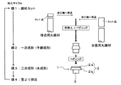
上記構成からなるリベット型接点1を製造するには、図3に示すように、先ず銀または銀合金からなる接点用丸線材から、リベット型接点1の接点部2aを形成するための長さ寸法を切り出して、冷間圧造ヘッダー機の加工軸へ移送して型内に挿入する。これと併行して、黄銅からなる台座用丸線材から、リベット型接点1の頭部2の基端部2aおよび台座部3を形成するための長さ寸法を切り出して、同様に加工軸へ移送して型内に挿入する。
In order to manufacture the
次いで、上記冷間圧造ヘッダー機によって、順次一次成形(予備成形)および二次成形(本成形)を行って、上記接点用丸線材および台座用丸線材を接合するとともに、リベット型接点1に形状に加工し、型から排出する。
Next, the cold forging header machine sequentially performs primary molding (preliminary molding) and secondary molding (main molding) to join the round wire for contact and the round wire for pedestal, and to form a
また、図2に示したディスク型接点5を製造するには、図4に示すように、先ず銀または銀合金からなる接点用丸線材から、ディスク型接点5の接点部6aを形成するための長さ寸法を切り出して、冷間圧造ヘッダー機の加工軸へ移送して型内に挿入する。これと併行して、黄銅からなる台座用丸線材から、ディスク型接点5の頭部6の基端部6bおよびプロジェクション7を形成するための長さ寸法を切り出して、同様に加工軸へ移送して型内に挿入する。
In order to manufacture the disk-
次いで、同様に上記冷間圧造ヘッダー機によって、順次一次成形(予備成形)および二次成形(本成形)を行って、上記接点用丸線材および台座用丸線材を接合するとともに、ディスク型接点の頭部6およびプロジェクション7の形状に加工し、型から排出する。
Next, in the same manner, the cold forging header machine sequentially performs primary molding (preliminary molding) and secondary molding (main molding) to join the round wire for contact and the round wire for pedestal. It is processed into the shape of the
本発明に係るリベット型接点(複合電気接点)として、接点材にAg−Sn−In系銀合金(Mx0:6〜18%、Ag:Bal)を用い、台金材に黄銅(合金番号2700)を用いたリベット型接点を10個製造した。また、比較例として、接点材に同一のAg−Sn−In系銀合金(Mx0:6〜18%、Ag:Bal)を用い、台座材に従来の銅を用いたリベット型接点を10個製造した。 As a rivet-type contact (composite electrical contact) according to the present invention, an Ag-Sn-In-based silver alloy (Mx0: 6 to 18%, Ag: Bal) is used for the contact material, and the base metal material is brass (alloy number 2700). Ten rivet-type contacts were used. As a comparative example, the same Ag-Sn-In silver alloy (Mx0: 6-18%, Ag: Bal) is used as the contact material, and 10 rivet-type contacts using conventional copper as the base material are manufactured. did.
そして、これらのリベット型接点について、図5に示すせん断測定器を用いて、固定ダイ20の凹部20a内に各々のリベット型接点を挿入してせん断刃21により接合部分Cのせん断強度を測定した。 And about these rivet type | mold contacts, each rivet type | mold contact was inserted in the recessed part 20a of the fixed die | dye 20 using the shear measuring device shown in FIG. .
図6は、その結果を示すものである。
同図から、台座材に黄銅を用い本発明に係るリベット型接点においては、台座材に従来の銅を用いた比較例のリベット型接点と比較して、接合強度が大幅に向上していることが判る。
FIG. 6 shows the result.
From the figure, in the rivet type contact according to the present invention using brass for the base material, the bonding strength is greatly improved compared to the rivet type contact of the comparative example using the conventional copper for the base material. I understand.
以上説明したように、上記リベット型接点1またはディスク型接点5によれば、台座材として黄銅(銅亜鉛合金)を用いることにより、接点材として高酸化物系の銀合金を用いた場合においても、従来よりも高い接合強度で接点材2a、6aを頭部2、6の基端部2b、6bに接合一体化させることができる。
As described above, according to the rivet-
加えて、黄銅は所望の展延性および溶接性を有しているために、リベット型接点1においては台座部3の端面3aを加締めて容易に台金に加締めることができるとともに、ディスク型接点5においては、容易にプロジェクション7におけるスポット溶接によって台金に固定することができる。
In addition, since brass has the desired spreadability and weldability, the
1 リベット型接点(複合電気接点)
2 頭部
2a 接点部
2b 基端部
3 台座部(固定部)
3a 先端面
5 ディスク型接点(複合電気接点)
6 頭部
6a 接点部
6b 基端部(固定部)
7 プロジェクション
1 Rivet contact (composite electrical contact)
2 Head part
6
7 Projection
Claims (2)
上記接点部を形成する接点材として銀または銀合金を用い、上記固定部を形成する台座材として黄銅を用いたことを特徴とする複合電気接点。 In a composite electrical contact comprising a contact part that is opened and closed and a fixing part to a base metal integrated with the contact part,
A composite electrical contact using silver or a silver alloy as a contact material for forming the contact portion and brass as a base material for forming the fixed portion.
Priority Applications (2)
| Application Number | Priority Date | Filing Date | Title |
|---|---|---|---|
| JP2016002194A JP2017123285A (en) | 2016-01-08 | 2016-01-08 | Composite electric contact |
| PCT/JP2016/088846 WO2017119356A1 (en) | 2016-01-08 | 2016-12-27 | Compound electric contact |
Applications Claiming Priority (1)
| Application Number | Priority Date | Filing Date | Title |
|---|---|---|---|
| JP2016002194A JP2017123285A (en) | 2016-01-08 | 2016-01-08 | Composite electric contact |
Publications (1)
| Publication Number | Publication Date |
|---|---|
| JP2017123285A true JP2017123285A (en) | 2017-07-13 |
Family
ID=59274167
Family Applications (1)
| Application Number | Title | Priority Date | Filing Date |
|---|---|---|---|
| JP2016002194A Pending JP2017123285A (en) | 2016-01-08 | 2016-01-08 | Composite electric contact |
Country Status (2)
| Country | Link |
|---|---|
| JP (1) | JP2017123285A (en) |
| WO (1) | WO2017119356A1 (en) |
Families Citing this family (1)
| Publication number | Priority date | Publication date | Assignee | Title |
|---|---|---|---|---|
| CN109166737A (en) * | 2018-10-15 | 2019-01-08 | 安徽银点电子科技有限公司 | A kind of rivet type electrical contact |
Family Cites Families (2)
| Publication number | Priority date | Publication date | Assignee | Title |
|---|---|---|---|---|
| JPS5159382A (en) * | 1974-11-21 | 1976-05-24 | Maruzen Kogyo Co Ltd | Tasodenkisetsutenno seizoho |
| JPS5320528A (en) * | 1976-08-10 | 1978-02-24 | Nippon Electric Co | Ac signal detector |
-
2016
- 2016-01-08 JP JP2016002194A patent/JP2017123285A/en active Pending
- 2016-12-27 WO PCT/JP2016/088846 patent/WO2017119356A1/en not_active Ceased
Also Published As
| Publication number | Publication date |
|---|---|
| WO2017119356A1 (en) | 2017-07-13 |
Similar Documents
| Publication | Publication Date | Title |
|---|---|---|
| US20040142607A1 (en) | Method of connecting and structure of connecting electric wire and connection terminal | |
| US6869328B2 (en) | Electrodes, method for production thereof and spark plugs with such an electrode | |
| JP5948385B2 (en) | Tape material having a clad structure for manufacturing a spark plug electrode | |
| US3562467A (en) | Electrical contact | |
| TW201324561A (en) | Method of manufacturing composite contact | |
| KR20080088514A (en) | Spark plug manufacturing method and spark plug | |
| KR20000070947A (en) | Soldering iron tip and method of making the same | |
| TWI675391B (en) | Tape-shaped contact member, method for manufacturing tape-shaped contact member, chip- shaped contact members, method for manufacturing electric contact and relay | |
| WO2017119356A1 (en) | Compound electric contact | |
| WO2014092173A1 (en) | Rivet contact and method for manufacturing same | |
| JP6349793B2 (en) | Commutator and motor with brush using commutator | |
| JP4885837B2 (en) | Manufacturing method of spark plug | |
| US2032926A (en) | Electrical contact | |
| JP2003036898A (en) | All-around crimping connection terminal and its connection method | |
| JPS5820085B2 (en) | composite electrical contacts | |
| US2281446A (en) | Electrical contact | |
| JP6597212B2 (en) | Conductive member | |
| JP2014164971A (en) | Terminal, terminal material and production method therefor and method of manufacturing terminal using the same | |
| CN113748577B (en) | Spark plug electrode and method of manufacturing the same | |
| JP2011070849A (en) | Terminal connection method of aluminum or aluminum alloy conductor | |
| JP2008204917A (en) | Spark plug and method of manufacturing spark plug | |
| JPH0574323A (en) | Fuse element | |
| JP2016207380A (en) | Electrical contact and method for manufacturing the same | |
| US3604877A (en) | Electrical contact assembly | |
| JP5767662B2 (en) | TERMINAL MATERIAL, ITS MANUFACTURING METHOD AND TERMINAL MANUFACTURING METHOD |
Legal Events
| Date | Code | Title | Description |
|---|---|---|---|
| RD01 | Notification of change of attorney |
Free format text: JAPANESE INTERMEDIATE CODE: A7421 Effective date: 20180201 |
|
| A521 | Written amendment |
Free format text: JAPANESE INTERMEDIATE CODE: A821 Effective date: 20180201 |