JP2017123371A - 電子機器保持スタンド - Google Patents
電子機器保持スタンド Download PDFInfo
- Publication number
- JP2017123371A JP2017123371A JP2016000409A JP2016000409A JP2017123371A JP 2017123371 A JP2017123371 A JP 2017123371A JP 2016000409 A JP2016000409 A JP 2016000409A JP 2016000409 A JP2016000409 A JP 2016000409A JP 2017123371 A JP2017123371 A JP 2017123371A
- Authority
- JP
- Japan
- Prior art keywords
- holding
- electronic device
- side tooth
- base
- tooth portion
- Prior art date
- Legal status (The legal status is an assumption and is not a legal conclusion. Google has not performed a legal analysis and makes no representation as to the accuracy of the status listed.)
- Granted
Links
- 230000007246 mechanism Effects 0.000 claims abstract description 31
- 238000012423 maintenance Methods 0.000 description 14
- 238000009434 installation Methods 0.000 description 13
- 238000010586 diagram Methods 0.000 description 4
- 238000000034 method Methods 0.000 description 3
- NJPPVKZQTLUDBO-UHFFFAOYSA-N novaluron Chemical compound C1=C(Cl)C(OC(F)(F)C(OC(F)(F)F)F)=CC=C1NC(=O)NC(=O)C1=C(F)C=CC=C1F NJPPVKZQTLUDBO-UHFFFAOYSA-N 0.000 description 1
Images







Landscapes
- Casings For Electric Apparatus (AREA)
- Devices For Indicating Variable Information By Combining Individual Elements (AREA)
- Telephone Set Structure (AREA)
Abstract
【解決手段】電子機器保持スタンドが、電子機器を保持する保持部と、前記保持部を支持する基部と、を有し、前記保持部は、前記基部が設置される面に平行な軸の周りに、前記保持部を回動させる回転装置を備え、前記回転装置は、所定の回転位置で、保持部側歯部と基部側歯部を嵌合させて前記保持部を固定し、当該固定状態において前記保持部側歯部と前記基部側歯部を当接させる機構を備える。
【選択図】 図20
Description
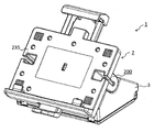
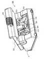
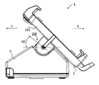
図1は、本発明を適用した電子機器保持スタンドの第1の実施の形態例に係る斜視図である。図1に示す本実施の形態例に係る電子機器保持スタンド1は、電子機器4を保持する保持部2と保持部2を支持する基部3を有し、保持部2が電子機器保持スタンド1(基部3)の設置面に水平(平行)な軸の周りに無負荷で回転でき、所定の複数の回転位置で歯部の嵌合により固定できる回転機構200を備える。これにより、保持した電子機器4を狭いスペースで、力をかけずに回転でき、かつ、確実に固定することができる。
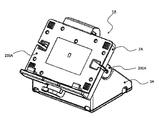
図16は、本発明を適用した電子機器保持スタンドの第2の実施の形態例に係る斜視図である。図2に示す本実施の形態例に係る電子機器保持スタンド1Aは、第1の実施の形態例に係る電子機器保持スタンド1と同様に、電子機器4Aを保持する保持部2Aと保持部2Aを支持する基部3Aを有し、保持部2Aが電子機器保持スタンド1A(基部3A)の設置面に水平(平行)な軸の周りに無負荷で回転でき、所定の複数の回転位置で歯部の嵌合により固定できる回転機構200Aを備える。更に、上記歯部の嵌合による固定の状態で、嵌合する歯部同士を確実に当接させる機構を備える。これらの特徴により、本電子機器保持スタンド1Aでは、保持した電子機器4Aを狭いスペースで、力をかけずに回転でき、かつ、ガタつくことなく確実に固定することができる。
Claims (4)
- 電子機器を保持する保持部と、
前記保持部を支持する基部と、を有し、
前記保持部は、前記基部が設置される面に平行な軸の周りに、前記保持部を回動させる回転装置を備え、
前記回転装置は、所定の回転位置で、保持部側歯部と基部側歯部を嵌合させて前記保持部を固定し、当該固定状態において前記保持部側歯部と前記基部側歯部を当接させる機構を備える
ことを特徴とする電子機器保持スタンド。 - 請求項1において、
前記回転装置は、前記保持部側歯部を、前記基部側歯部と嵌合する際に移動する方向である嵌合方向へ押圧する押え部材を備え、当該押え部材と前記保持部側歯部との当接面が、前記嵌合方向に垂直な方向に対して角度を有する
ことを特徴とする電子機器保持スタンド。 - 請求項2において、
前記保持部側歯部は、前記嵌合方向に移動する際に、前記保持部側歯部の先端よりも前に前記保持部側歯部の側面が前記基部側歯部に当接する形状である
ことを特徴とする電子機器保持スタンド。 - 請求項1乃至3のいずれか1項において、
前記保持部は、前記固定状態で圧縮されて前記保持部に回転力を与える弾性体の部材を、前記基部との間に備える
ことを特徴とする電子機器保持スタンド。
Priority Applications (2)
| Application Number | Priority Date | Filing Date | Title |
|---|---|---|---|
| JP2016000409A JP6634830B2 (ja) | 2016-01-05 | 2016-01-05 | 電子機器保持スタンド |
| US15/358,693 US10473257B2 (en) | 2015-11-26 | 2016-11-22 | Electronic device support stand |
Applications Claiming Priority (1)
| Application Number | Priority Date | Filing Date | Title |
|---|---|---|---|
| JP2016000409A JP6634830B2 (ja) | 2016-01-05 | 2016-01-05 | 電子機器保持スタンド |
Publications (2)
| Publication Number | Publication Date |
|---|---|
| JP2017123371A true JP2017123371A (ja) | 2017-07-13 |
| JP6634830B2 JP6634830B2 (ja) | 2020-01-22 |
Family
ID=59306000
Family Applications (1)
| Application Number | Title | Priority Date | Filing Date |
|---|---|---|---|
| JP2016000409A Active JP6634830B2 (ja) | 2015-11-26 | 2016-01-05 | 電子機器保持スタンド |
Country Status (1)
| Country | Link |
|---|---|
| JP (1) | JP6634830B2 (ja) |
Citations (4)
| Publication number | Priority date | Publication date | Assignee | Title |
|---|---|---|---|---|
| JPH0210576U (ja) * | 1988-07-05 | 1990-01-23 | ||
| JPH11261248A (ja) * | 1998-03-12 | 1999-09-24 | Seiko Epson Corp | 電子機器 |
| JP2003312374A (ja) * | 2002-02-20 | 2003-11-06 | A One Kasei Kogyo Kk | 車載用小型電子機器スタンド |
| JP2006268036A (ja) * | 2005-02-28 | 2006-10-05 | Seiko Epson Corp | 情報処理装置 |
-
2016
- 2016-01-05 JP JP2016000409A patent/JP6634830B2/ja active Active
Patent Citations (4)
| Publication number | Priority date | Publication date | Assignee | Title |
|---|---|---|---|---|
| JPH0210576U (ja) * | 1988-07-05 | 1990-01-23 | ||
| JPH11261248A (ja) * | 1998-03-12 | 1999-09-24 | Seiko Epson Corp | 電子機器 |
| JP2003312374A (ja) * | 2002-02-20 | 2003-11-06 | A One Kasei Kogyo Kk | 車載用小型電子機器スタンド |
| JP2006268036A (ja) * | 2005-02-28 | 2006-10-05 | Seiko Epson Corp | 情報処理装置 |
Also Published As
| Publication number | Publication date |
|---|---|
| JP6634830B2 (ja) | 2020-01-22 |
Similar Documents
| Publication | Publication Date | Title |
|---|---|---|
| US10473257B2 (en) | Electronic device support stand | |
| JP2694013B2 (ja) | 電子機器 | |
| EP2444873B1 (en) | Support assembly and computer device having the same | |
| US20190274228A1 (en) | Support mechanism and mobile terminal | |
| KR101888154B1 (ko) | 전자기기 | |
| TW201235818A (en) | Hinge device and docking station | |
| JP2014225189A (ja) | 電子機器 | |
| JP2007233232A (ja) | 表示画面支持機構 | |
| JP4873083B2 (ja) | 半導体試験装置 | |
| CN105492785B (zh) | 开闭装置以及电子设备 | |
| US20130078023A1 (en) | Key switch structure | |
| US11052830B2 (en) | Display holder | |
| JP2012009386A5 (ja) | ||
| US10032054B2 (en) | Rotatable assembly and scanning device including the same | |
| JP2007193245A (ja) | 表示画面支持機構 | |
| JP6634830B2 (ja) | 電子機器保持スタンド | |
| JP2017098807A (ja) | 電子機器保持スタンド | |
| CN206371017U (zh) | 电子设备保持支架 | |
| JP5356435B2 (ja) | 電子機器 | |
| JP2022067198A (ja) | 携帯用情報機器及びディスプレイアセンブリ | |
| EP3706103A1 (en) | Fixing structure for fixing reflective sheet and display brightness detection device | |
| JP4561866B2 (ja) | 表示画面支持機構およびテレビジョン装置 | |
| US9285838B2 (en) | Electronic device | |
| US20140026366A1 (en) | Rotary shaft device | |
| JP2012183677A (ja) | 回動操作装置及び画像記録装置 |
Legal Events
| Date | Code | Title | Description |
|---|---|---|---|
| RD05 | Notification of revocation of power of attorney |
Free format text: JAPANESE INTERMEDIATE CODE: A7425 Effective date: 20180906 |
|
| A621 | Written request for application examination |
Free format text: JAPANESE INTERMEDIATE CODE: A621 Effective date: 20181016 |
|
| RD03 | Notification of appointment of power of attorney |
Free format text: JAPANESE INTERMEDIATE CODE: A7423 Effective date: 20181119 |
|
| A977 | Report on retrieval |
Free format text: JAPANESE INTERMEDIATE CODE: A971007 Effective date: 20190814 |
|
| A131 | Notification of reasons for refusal |
Free format text: JAPANESE INTERMEDIATE CODE: A131 Effective date: 20190903 |
|
| A521 | Request for written amendment filed |
Free format text: JAPANESE INTERMEDIATE CODE: A523 Effective date: 20191031 |
|
| TRDD | Decision of grant or rejection written | ||
| A01 | Written decision to grant a patent or to grant a registration (utility model) |
Free format text: JAPANESE INTERMEDIATE CODE: A01 Effective date: 20191119 |
|
| A61 | First payment of annual fees (during grant procedure) |
Free format text: JAPANESE INTERMEDIATE CODE: A61 Effective date: 20191202 |
|
| R150 | Certificate of patent or registration of utility model |
Ref document number: 6634830 Country of ref document: JP Free format text: JAPANESE INTERMEDIATE CODE: R150 |