JP2017123706A - Power conversion device and control method thereof - Google Patents
Power conversion device and control method thereof Download PDFInfo
- Publication number
- JP2017123706A JP2017123706A JP2016000443A JP2016000443A JP2017123706A JP 2017123706 A JP2017123706 A JP 2017123706A JP 2016000443 A JP2016000443 A JP 2016000443A JP 2016000443 A JP2016000443 A JP 2016000443A JP 2017123706 A JP2017123706 A JP 2017123706A
- Authority
- JP
- Japan
- Prior art keywords
- voltage
- phase
- converter
- terminals
- switching
- Prior art date
- Legal status (The legal status is an assumption and is not a legal conclusion. Google has not performed a legal analysis and makes no representation as to the accuracy of the status listed.)
- Granted
Links
Images


Landscapes
- Rectifiers (AREA)
- Inverter Devices (AREA)
Abstract
【課題】短時間の不平衡事故が発生した場合にも、運転を継続できる電力変換装置及びその制御方法を提供する。【解決手段】実施形態によれば、第1及び第2変換器と制御ユニットとを備えた電力変換装置が提供される。第1変換器は、ブリッジ接続された複数のスイッチング素子と、各スイッチング素子に逆並列に接続された複数の整流素子と、を有し、各スイッチング素子のスイッチングにより、入力された第1三相交流電圧を直流電圧に変換する。第2変換器は、直流電圧を第2三相交流電圧に変換する。制御ユニットは、第1三相交流電圧の位相を検出し、その位相を基に変調率を1.2以上とした固定パルスパターン方式で各スイッチング素子を制御し、第1三相交流電圧の角速度を検出し、その角速度と基準値との偏差が一定値以上である場合に各スイッチング素子をオフ状態にする。【選択図】図1A power conversion device capable of continuing operation even when a short-time unbalance accident occurs and a control method therefor are provided. According to an embodiment, a power conversion device including first and second converters and a control unit is provided. The first converter includes a plurality of switching elements connected in a bridge and a plurality of rectifying elements connected in antiparallel to each switching element, and the first three-phase input by switching of each switching element Converts AC voltage to DC voltage. The second converter converts the DC voltage into a second three-phase AC voltage. The control unit detects the phase of the first three-phase AC voltage, controls each switching element by a fixed pulse pattern method with a modulation rate of 1.2 or more based on the phase, and the angular velocity of the first three-phase AC voltage. When the deviation between the angular velocity and the reference value is a certain value or more, each switching element is turned off. [Selection] Figure 1
Description
本発明の実施形態は、電力変換装置及びその制御方法に関する。 Embodiments described herein relate generally to a power conversion device and a control method thereof.
交流電力を直流電力に変換する電圧形コンバータと、直流電力を所望の周波数及び電圧の交流電力に変換して電動機などの負荷に供給するインバータと、を備えた電力変換装置がある。こうした電力変換装置は、例えば、圧延プラントなどに用いられている。 There is a power conversion device including a voltage source converter that converts AC power into DC power, and an inverter that converts the DC power into AC power having a desired frequency and voltage and supplies the AC power to a load such as an electric motor. Such a power converter is used in, for example, a rolling plant.
圧延プラントにおいては、圧延機用の電力変換装置の負荷電流が大きい。このため、短時間の1線地絡や2線短絡などの不平衡事故が発生した場合にコンバータの制御を継続していると、電源の位相情報にずれが生じ、コンバータが短時間で直流過電流の故障に至ってしまうことがある。 In a rolling plant, the load current of a power converter for a rolling mill is large. For this reason, if the control of the converter is continued when an unbalanced accident such as a short 1-wire ground fault or a 2-wire short-circuit occurs, the phase information of the power supply will be shifted, and the converter will have a DC overload in a short time. It may lead to current failure.
一方、短時間の交流電源の異常が発生した時に、コンバータの制御を停止して同時にインバータの負荷である電動機の出力を抑制すると、圧延機が失速し、圧延を継続できなくなってしまう。圧延を継続するためには、短時間のコンバータの制御停止中でもインバータの出力に制約のない電力変換装置が必要となる。 On the other hand, when the short-time AC power supply abnormality occurs, if the control of the converter is stopped and simultaneously the output of the electric motor that is the load of the inverter is suppressed, the rolling mill stalls and rolling cannot be continued. In order to continue rolling, a power conversion device that does not restrict the output of the inverter is required even when the control of the converter is stopped for a short time.
例えば、特許文献1では、コンバータから出力される直流電圧が下限値以下になった場合に、コンバータのスイッチング素子をゲートオフにし、ダイオード整流に切り替えるようにしている。そして、コンバータが力行運転中の場合には、直流電圧が下がらないように、負荷の電動機の出力パワーをゼロにする。電動機の負荷が圧延機の場合、電動機の出力の低減は、圧延機の失速につながる。従って、操業を継続することができなくなってしまう。
For example, in
このため、電力変換装置では、短時間の1線地絡や2線短絡などの不平衡事故が発生した場合にも、運転を継続できるようにすることが望まれる。 For this reason, in a power converter, it is desired to be able to continue operation even when an unbalanced accident such as a short 1-wire ground fault or a 2-wire short-circuit occurs.
本発明の実施形態は、短時間の1線地絡や2線短絡などの不平衡事故が発生した場合にも、運転を継続できる電力変換装置及びその制御方法を提供する。 Embodiments of the present invention provide a power converter that can continue operation even when an unbalanced accident such as a short-circuit 1-wire ground fault or 2-wire short-circuit occurs, and a control method thereof.
本発明の実施形態によれば、第1変換器と、複数の平滑コンデンサと、第2変換器と、電圧計と、制御ユニットと、を備えた電力変換装置が提供される。前記第1変換器は、ブリッジ接続された複数のスイッチング素子と、前記複数のスイッチング素子のそれぞれに逆並列に接続された複数の整流素子と、3つの交流端子と、少なくとも3つの直流端子と、を有し、前記複数のスイッチング素子のスイッチングにより、前記3つの交流端子から入力された第1三相交流電圧を、正電位、負電位及び中性点電位の少なくとも3レベルを有する直流電圧に変換し、前記直流電圧を前記少なくとも3つの直流端子から出力する。前記複数の平滑コンデンサは、前記少なくとも3つの直流端子のそれぞれの間に設けられる。前記第2変換器は、前記少なくとも3つの直流端子に接続されるとともに、交流負荷に接続され、前記直流電圧を前記交流負荷に応じた第2三相交流電圧に変換し、前記第2三相交流電圧を前記交流負荷に供給する。前記電圧計は、前記第1三相交流電圧の各相の電圧値を検出する。前記制御ユニットは、前記電圧計の検出結果を基に前記第1三相交流電圧の各相の位相を検出し、検出された前記位相を基に、前記第1三相交流電圧の線間電圧と前記直流電圧との変調率を1.2以上とした固定パルスパターン方式により、前記第1変換器の前記複数のスイッチング素子のスイッチングを制御するとともに、検出された前記位相を基に、前記第1三相交流電圧の各相の角速度を検出し、検出された前記角速度と角速度基準値との偏差が一定値以上である場合に、前記複数のスイッチング素子をオフ状態にする。 According to the embodiment of the present invention, a power converter including a first converter, a plurality of smoothing capacitors, a second converter, a voltmeter, and a control unit is provided. The first converter includes a plurality of bridge-connected switching elements, a plurality of rectifying elements connected in antiparallel to the plurality of switching elements, three AC terminals, and at least three DC terminals, And the first three-phase AC voltage input from the three AC terminals is converted into a DC voltage having at least three levels of a positive potential, a negative potential, and a neutral point potential by switching of the plurality of switching elements. The DC voltage is output from the at least three DC terminals. The plurality of smoothing capacitors are provided between each of the at least three DC terminals. The second converter is connected to the at least three DC terminals and connected to an AC load, converts the DC voltage to a second three-phase AC voltage corresponding to the AC load, and the second three-phase An alternating voltage is supplied to the alternating load. The voltmeter detects a voltage value of each phase of the first three-phase AC voltage. The control unit detects a phase of each phase of the first three-phase AC voltage based on a detection result of the voltmeter, and a line voltage of the first three-phase AC voltage based on the detected phase. And switching of the plurality of switching elements of the first converter is controlled by a fixed pulse pattern method in which a modulation rate between the DC voltage and the DC voltage is 1.2 or more, and the first phase is determined based on the detected phase. (1) The angular velocity of each phase of the three-phase AC voltage is detected, and when the deviation between the detected angular velocity and the angular velocity reference value is a predetermined value or more, the plurality of switching elements are turned off.
短時間の1線地絡や2線短絡などの不平衡事故が発生した場合にも、運転を継続できる電力変換装置及びその制御方法が提供される。 Provided are a power conversion device and a control method thereof that can continue operation even when an unbalanced accident such as a short-time 1-wire ground fault or 2-wire short-circuit occurs.
以下に、各実施の形態について図面を参照しつつ説明する。
なお、図面は模式的または概念的なものであり、各部分の厚みと幅との関係、部分間の大きさの比率などは、必ずしも現実のものと同一とは限らない。また、同じ部分を表す場合であっても、図面により互いの寸法や比率が異なって表される場合もある。
なお、本願明細書と各図において、既出の図に関して前述したものと同様の要素には同一の符号を付して詳細な説明は適宜省略する。
Each embodiment will be described below with reference to the drawings.
The drawings are schematic or conceptual, and the relationship between the thickness and width of each part, the size ratio between the parts, and the like are not necessarily the same as actual ones. Further, even when the same part is represented, the dimensions and ratios may be represented differently depending on the drawings.
Note that, in the present specification and each drawing, the same elements as those described above with reference to the previous drawings are denoted by the same reference numerals, and detailed description thereof is omitted as appropriate.
(第1の実施形態)
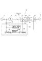
図1は、第1の実施形態に係る電力変換装置を模式的に表すブロック図である。
図1に表したように、電力変換装置10は、第1変換器11と、第2変換器12と、一対の平滑コンデンサ13、14と、制御ユニット15と、電圧計16と、電流計17と、を備える。
(First embodiment)
FIG. 1 is a block diagram schematically illustrating the power conversion apparatus according to the first embodiment.
As shown in FIG. 1, the
第1変換器11は、3つの交流端子11r、11s、11tと、少なくとも3つの直流端子11p、11n、11cと、を有する。各交流端子11r、11s、11tは、変圧器4を介して交流電源2に接続される。交流電源2は、三相交流電源である。各交流端子11r、11s、11tは、交流電源2の三相交流電圧の各相に接続される。これにより、第1変換器11には、各交流端子11r、11s、11tを介して三相交流電圧が入力される。変圧器4は、電力変換装置10に設けてもよいし、電力変換装置10とは別に設けてもよい。
The
第1変換器11は、入力された三相交流電圧(第1三相交流電圧)を正電位P、負電位N及び中性点電位Cの少なくとも3レベルを有する直流電圧に変換にする。この例では、三相交流電圧を上記の3レベルに変換する場合について説明する。以下では、各直流端子11p、11n、11cを、それぞれ正電位端子11p、負電位端子11n、中性点端子11cと称す。第1変換器11は、3レベルに限ることなく、三相交流電圧をより多数のレベルを有する直流電圧に変換してもよい。この場合、直流端子の数は、4つ以上でもよい。
The
第1変換器11は、正電位端子11pを正電位Pに設定し、負電位端子11nを負電位Nに設定し、中性点端子11cを中性点電位Cに設定する。中性点電位Cは、正電位Pと負電位Nとの中間の電位である。これにより、第1変換器11は、正電位端子11pと中性点端子11cとの間、及び、中性点端子11cと負電位端子11nとの間のそれぞれに、直流電圧Vdを発生させる。従って、正電位端子11pと負電位端子11nとの間の電圧は、2Vdである。
The
平滑コンデンサ13は、正電位端子11pと中性点端子11cとの間に設けられる。平滑コンデンサ13は、正電位端子11pと中性点端子11cとの間に電気的に接続される。平滑コンデンサ14は、中性点端子11cと負電位端子11nとの間に設けられる。平滑コンデンサ14は、中性点端子11cと負電位端子11nとの間に電気的に接続される。平滑コンデンサ13、14は、直流電圧Vdを平滑化する。第1変換器11に4つ以上の直流端子が設けられる場合、平滑コンデンサは、各直流端子のそれぞれの間に設けられる。平滑コンデンサは、直流端子の数に応じて複数設けられる。
The
第2変換器12は、各直流端子11p、11n、11cに接続されるとともに、誘導電動機6に接続される。誘導電動機6は、三相誘導電動機である。第2変換器12は、第1変換器11から入力された直流電圧を、誘導電動機6に応じた所望の周波数及び電圧値の三相交流電圧(第2三相交流電圧)に変換し、その三相交流電圧を誘導電動機6に供給する。これにより、第2変換器12は、誘導電動機6を駆動する。
The
このように、電力変換装置10は、誘導電動機6の力行運転を行う。第1変換器11は、3レベル式の電圧形コンバータである。第2変換器12は、電圧形のインバータである。また、電力変換装置10は、誘導電動機6で発生した三相交流電圧を交流電源2に応じた三相交流電圧に変換し、変換後の三相交流電圧を電源系統に供給する。すなわち、電力変換装置10は、誘導電動機6の回生運転を行うこともできる。この場合には、第1変換器11がインバータとして機能し、第2変換器12がコンバータとして機能する。第2変換器12が三相交流電圧を供給する交流負荷は、誘導電動機6に限ることなく、他の交流負荷でもよい。電力変換装置10は、誘導電動機6の運転を行う他に、例えば、同期電動機の運転も行う。
As described above, the
電圧計16は、交流電源2の三相交流の各相の電圧値を検出する。電圧計16は、検出した各相の電圧値を制御ユニット15に入力する。電流計17は、交流電源2の三相交流の各相の電流値を検出する。電流計17は、検出した各相の電流値を制御ユニット15に入力する。
The
制御ユニット15は、電圧計16及び電流計17の各検出結果を基に、第1変換器11及び第2変換器12の動作を制御する。制御ユニット15は、第1変換器11による三相交流電圧から直流電圧への変換を制御する。制御ユニット15は、第2変換器12による直流電圧から三相交流電圧への変換を制御する。第2変換器12の動作は、制御ユニット15とは別の制御ユニットによって制御してもよい。
The
図2は、第1の実施形態に係る変換器を模式的に表すブロック図である。
図2に表したように、第1変換器11は、ブリッジ接続された複数のスイッチング素子21と、各スイッチング素子21のそれぞれに逆並列に接続された複数の整流素子22と、を有する。この例において、第1変換器11は、複数の整流素子23をさらに有する。
FIG. 2 is a block diagram schematically illustrating the converter according to the first embodiment.
As illustrated in FIG. 2, the
スイッチング素子21は、一対の主端子と、制御端子と、を有する。制御端子は、各主端子間に電流が流れるオン状態と、各主端子間に実質的に電流が流れないオフ状態と、の切り替えに用いられる。スイッチング素子21には、例えば、GTO(Gate Turn Off thyristor)やIGBT(Insulated Gate Bipolar Transistor)などの自己消弧素子が用いられる。制御端子は、例えば、ゲート端子である。
The switching
第1変換器11は、三相ブリッジ型であり、6つのアームAR、AS、AT、AX、AY、AZを有する。各交流端子11r、11s、11tに接続される各相アームAR、AS、AT、AX、AY、AZのそれぞれの構成は、実質的に同じである。従って、ここでは例示として交流端子11r(R相)に接続される2つのアームAR、AXについて説明する。
The
正側のアームARは、直列接続の2つのスイッチング素子SR1、SR2と、これらのスイッチング素子SR1、SR2のそれぞれに逆並列に接続された整流素子DR1、DR2と、各スイッチング素子SR1、SR2の直列接続点と中性点端子11cとの間に接続された整流素子DR3と、を有する。
The positive-side arm AR includes two switching elements SR1 and SR2 connected in series, rectifying elements DR1 and DR2 connected in antiparallel to each of these switching elements SR1 and SR2, and a series of switching elements SR1 and SR2. And a rectifying element DR3 connected between the connection point and the
同様に、負側のアームAXは、直列接続の2つのスイッチング素子SX1、SX2と、これらのスイッチング素子SX1、SX2のそれぞれに逆並列に接続された整流素子DX1、DX2と、各スイッチング素子SX1、SX2の直列接続点と中性点端子11cとの間に接続された整流素子DX3と、を有する。
Similarly, the negative arm AX includes two switching elements SX1, SX2 connected in series, rectifying elements DX1, DX2 connected in antiparallel to each of these switching elements SX1, SX2, and each switching element SX1, And a rectifying element DX3 connected between the series connection point of SX2 and the
両アームAR、AXは、正電位端子11pと負電位端子11nとの間に直列に接続され、両アームAR、AXの直列接続点がR相の交流端子11rに接続される。スイッチング素子SR1、SR2の直列接続点の電位は、整流素子DR3を介して中性点電位Cにクランプされる。同様に、スイッチング素子SX1、SX2の直列接続点の電位は、整流素子DX3を介して中性点電位Cにクランプされる。整流素子DR1、DR2、DX1、DX2(各整流素子22)は、いわゆる還流ダイオードである。整流素子DR3、DX3(各整流素子23)は、いわゆるクランプダイオードである。
Both arms AR and AX are connected in series between a positive potential terminal 11p and a negative potential terminal 11n, and a series connection point of both arms AR and AX is connected to an R-
アームAS、ATの構成は、アームARの構成と実質的に同じである。アームAY、AZの構成は、アームAXの構成と実質的に同じである。これにより、各スイッチング素子21のスイッチングに応じて、交流端子11r、11s、11tの電位が、正電位端子11p、負電位端子11n、及び中性点端子11cの3レベルのいずれかの電位にクランプされる。
The configuration of the arms AS and AT is substantially the same as the configuration of the arm AR. The configuration of the arms AY and AZ is substantially the same as the configuration of the arm AX. Thereby, the potential of the
第2変換器12の構成は、第1変換器11の構成と実質的に同じであるから、詳細な説明は省略する。第2変換器12においては、各平滑コンデンサ13、14と接続された側が直流側(正電位端子11p、負電位端子11n、中性点端子11cに相当)となり、誘導電動機6と接続された側が交流側(交流端子11r、11s、11tに相当)となる。制御ユニット15は、第2変換器12の各スイッチング素子のスイッチングを制御することにより、第2変換器12による直流電圧から三相交流電圧への変換を制御する。
Since the configuration of the
制御ユニット15は、位相検出器30と、有効分・無効分電流検出器32と、ゲート制御部34と、を有する。位相検出器30には、電圧計16の検出結果が入力される。位相検出器30は、電圧計16の検出結果を基に、交流電源2の三相交流電圧の各相の位相を検出する。
The
また、位相検出器30は、検出した位相の単位時間当たりの変化量を基に、交流電源2の三相交流電圧の各相の角速度を検出する。換言すれば、位相検出器30は、交流電源2の三相交流電圧の各相の周波数を検出する。位相検出器30は、検出した各相の位相情報及び角速度情報をゲート制御部34に入力する。
Further, the
有効分・無効分電流検出器32には、電圧計16の検出結果、及び、電流計17の検出結果が入力される。有効分・無効分電流検出器32は、入力された電圧計16及び電流計17の各検出結果を基に、交流電源2側から第1変換器11に供給される電流の有効電流Ip及び無効電流Iqを演算する。有効分・無効分電流検出器32は、演算した有効電流Ip及び無効電流Iqをゲート制御部34に入力する。
The detection result of the
ゲート制御部34は、固定パルスパターン方式により、第1変換器11の各スイッチング素子21のスイッチングを制御するための制御信号(例えばゲート信号)を生成する。ゲート制御部34は、生成した各制御信号を各スイッチング素子21の制御端子に入力する。これにより、ゲート制御部34は、各スイッチング素子21のオン・オフを切り替え、第1変換器11の動作を制御する。
The
固定パルスパターン方式とは、毎周期同一のパルスパターンを発生し続ける方式である。パルスパターンの基本周波数は、交流電源2の周波数と同期する。ゲート制御部34は、位相検出器30で検出された位相情報を基に、パルスパターンの基本周波数を交流電源2の周波数に同期させる。なお、固定パルスパターン方式については、例えば、特許第3630621号、特許第4015795号、及び、特許第5411031号などにより詳しく説明されている。
The fixed pulse pattern method is a method of continuously generating the same pulse pattern every cycle. The basic frequency of the pulse pattern is synchronized with the frequency of the
また、ゲート制御部34は、例えば、有効分・無効分電流検出器32で検出された有効電流Ip及び無効電流Iqを基に、有効電流Ip及び無効電流Iqの基準値との偏差をゼロにするための位相の補正量を算出する。そして、ゲート制御部34は、交流電源2の位相から補正量の分だけ位相をシフトさせたパルスパターンを生成する。なお、パルスパターンの位相は、位相検出器30の位相情報のみで決定してもよい。
Further, the
図3は、第1の実施形態に係るパルスパターンの一例を表すグラフ図である。
図3は、R相の各スイッチング素子SR1、SR2、SX1、SX2に入力する制御信号GR1、GR2、GX1、GX2、及び、R相の電圧波形Vsrの一例である。図3に表したように、パルスパターンの1/4周期の波形は、90°を挟んで左右対称である。また、3レベル変換器のための正側のパルスと負側のパルスは、上下対称である。さらに、三相各相のパルスパターンは、互いに120°ずれた同一のパルスパターンである。従って、1/4周期のパルスパターンが決定されれば、全てのパルスパターンが決まる。図3では、交流電源半周期あたり3パルスの場合を例示しているが、パルス数は、任意でよい。
FIG. 3 is a graph showing an example of a pulse pattern according to the first embodiment.
FIG. 3 is an example of the control signals GR1, GR2, GX1, GX2 and the R-phase voltage waveform Vsr input to the R-phase switching elements SR1, SR2, SX1, SX2. As shown in FIG. 3, the waveform of the ¼ period of the pulse pattern is symmetrical with respect to 90 °. The positive and negative pulses for the three-level converter are vertically symmetrical. Furthermore, the pulse patterns of the three phases are the same pulse patterns that are shifted from each other by 120 °. Therefore, if a ¼ period pulse pattern is determined, all pulse patterns are determined. Although FIG. 3 illustrates the case of 3 pulses per half cycle of the AC power supply, the number of pulses may be arbitrary.
ゲート制御部34は、上記の固定パルスパターン方式の制御において、交流電源2の線間電圧と正側または負側の直流電圧Vdとの変調率を1.2以上にする。変調率をm、交流電源2の線間電圧をVaとした時、変調率mは、以下の(1)式によって求めることができる。
m=(√2/√3)Va/Vd (1)
すなわち、線間電圧Vaに対して直流電圧Vdを小さくする。これにより、変調率mを1.2以上にすることができる。
The
m = (√2 / √3) Va / Vd (1)
That is, the DC voltage Vd is made smaller than the line voltage Va. Thereby, the modulation factor m can be 1.2 or more.
すなわち、線間電圧Vaに対して、直流電圧Vdを以下の(1A)式の値より小さくする。これにより、変調率mを1.2以上にすることができる。
Vd=(√2/√3/1.2)Va (1A)
That is, with respect to the line voltage Va, the DC voltage Vd is made smaller than the value of the following expression (1A). Thereby, the modulation factor m can be 1.2 or more.
Vd = (√2 / √3 / 1.2) Va (1A)
変調率mは、例えば、図3のパルスP1のタイミングを調整することによって変化させることができる。パルスP1のタイミングを遅らせると、中央のパルス幅が減少し、これにともなって変調率mが減少する。反対に、パルスP1のタイミングを早めると、中央のパルス幅が増大し、変調率mも増大する。これにより、変調率mを任意に設定することができる。また、ゲート制御部34は、例えば、変調率mを1.5以下にする。
The modulation factor m can be changed, for example, by adjusting the timing of the pulse P1 in FIG. If the timing of the pulse P1 is delayed, the central pulse width decreases, and the modulation factor m decreases accordingly. Conversely, if the timing of the pulse P1 is advanced, the central pulse width increases and the modulation factor m also increases. Thereby, the modulation factor m can be set arbitrarily. Further, the
ゲート制御部34は、誘導電動機6の力行運転を行う場合に、位相検出器30から入力された角速度情報を基に、検出された角速度と角速度基準値との偏差が一定値以上であるか否かを判定する。ゲート制御部34は、三相交流電圧の各相のそれぞれについて、上記の判定を行う。角速度基準値は、例えば、交流電源2の周波数に応じて決定される。例えば、交流電源2の周波数が50(Hz)である場合、角速度基準値は、100π(rad/s)である。ゲート制御部34は、例えば、角速度基準値の±10%を一定値として判定を行う。例えば、交流電源2の周波数が50(Hz)である場合、ゲート制御部34は、検出された角速度と角速度基準値との偏差が±10π(rad/s)以上の時に、一定値以上であると判定する。
When the power control operation of the
ゲート制御部34は、各相のそれぞれについて一定値未満であると判定した場合、上記のように、変調率1.2以上の固定パルスパターン方式で第1変換器11の各スイッチング素子21のスイッチングを制御する。
When the
一方、ゲート制御部34は、各相の少なくとも1つについて一定値以上であると判定した場合、第1変換器11の各スイッチング素子21をオフ状態にする。ゲート制御部34は、各スイッチング素子21をオフ状態にする制御信号を生成し、その制御信号を各スイッチング素子21の制御端子に入力することにより、各スイッチング素子21のそれぞれをオフ状態にする。これにより、ゲート制御部34は、第1変換器11を各整流素子22によるダイオードコンバータとして第1変換器11を動作させる。
On the other hand, if the
このように、ゲート制御部34は、変調率1.2以上の固定パルスパターン方式により電圧形コンバータとして第1変換器11を動作させるコンバータモードと、ダイオードコンバータとして第1変換器11を動作させるダイオード整流モードと、を有する。
As described above, the
ゲート制御部34は、偏差が一定値以上であると判定した後、一定値未満の状態に復帰した場合、第1変換器11の動作をダイオード整流モードからコンバータモードに戻す。すなわち、ゲート制御部34は、複数のスイッチング素子21をオフ状態にした後、偏差が一定値未満の状態に復帰した場合に、固定パルスパターン方式による複数のスイッチング素子21の制御を再開する。
When the
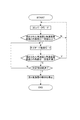
図4は、第1の実施形態に係る電力変換装置の動作を模式的に表すフローチャートである。
図4は、誘導電動機6を力行運転する場合の動作を模式的に表す。
図4に表したように、電力変換装置10では、誘導電動機6の力行運転を行う場合、制御ユニット15のゲート制御部34が、変調率1.2以上の固定パルスパターン方式で第1変換器11の各スイッチング素子21のスイッチングを制御し、第1変換器11をコンバータモードで動作させる。これにより、ゲート制御部34は、交流電源2の三相交流電圧を直流電圧に変換する。また、制御ユニット15は、第2変換器12の動作を制御し、第1変換器11から出力された直流電圧を誘導電動機6に対応した三相交流電圧に変換する。第2変換器12は、変換した三相交流電圧を誘導電動機6に供給する。これにより、誘導電動機6が力行運転される。
FIG. 4 is a flowchart schematically showing the operation of the power conversion device according to the first embodiment.
FIG. 4 schematically shows an operation when the
As shown in FIG. 4, in the
ゲート制御部34は、誘導電動機6を力行運転する場合、第1変換器11の動作を制御するとともに、三相交流電圧の各相のそれぞれについて、検出された角速度と角速度基準値との偏差が一定値以上であるか否かを判定する。
When powering the
ゲート制御部34は、各相のそれぞれについて一定値未満であると判定した場合、コンバータモードによる第1変換器11の動作を継続させる。
If the
一方、ゲート制御部34は、各相の少なくとも1つについて一定値以上であると判定した場合、各スイッチング素子21をオフ状態にし、第1変換器11の動作をコンバータモードからダイオード整流モードに切り替える。
On the other hand, if the
交流電源2の三相交流電圧のうちの1相又は2相において、検出された角速度と角速度基準値との偏差が一定値以上であると判定された場合、交流電源2に不平衡事故が発生していると考えられる。交流電源2に不平衡事故が発生すると、位相検出器30での位相検出にずれが生じる可能性がある。このため、不平衡事故時に第1変換器11をコンバータモードで動作させ続けると、場合によっては、直流過電流などにより、第1変換器11や第2変換器12が故障してしまう。
When it is determined that the deviation between the detected angular velocity and the angular velocity reference value is greater than or equal to a certain value in one or two phases of the three-phase AC voltage of the
また、第1変換器11をダイオード整流モードで動作させた場合の変調率mは、例えば、約1.21である。このため、コンバータモード時の変調率mとダイオード整流モード時の変調率mとの差が大きい場合には、第1変換器11をダイオード整流モードに切り替えた時に、直流電圧が過度に大きくなったり、小さくなったりしてしまう。
Further, the modulation factor m when the
例えば、コンバータモード時の変調率mを1.2よりも小さくすると、第1変換器11をダイオード整流モードに切り替えた時に、直流電圧Vdが小さくなり、誘導電動機6の力行運転を継続することができなくなってしまう。例えば、第1変換器11をPWM制御で動作させる場合、三相のうちの一相を120°の期間オンを継続する、いわゆる二相変調の時に、変調率mが最大になると考えられる。この時の変調率mは1.15であり、1.2よりも小さい。
For example, if the modulation factor m in the converter mode is smaller than 1.2, when the
反対に、コンバータモード時の変調率mを1.5よりも大きくすると、第1変換器11をダイオード整流モードに切り替えた時に、直流電圧Vdが大きくなり、第1変換器11や第2変換器12の故障が懸念される。
On the contrary, if the modulation factor m in the converter mode is larger than 1.5, the DC voltage Vd increases when the
本実施形態に係る電力変換装置10では、コンバータモードにおいて、変調率1.2以上の固定パルスパターン方式により、第1変換器11を動作させる。これにより、第1変換器11をダイオード整流モードに切り替えた時の直流電圧Vdの変動を抑制することができる。従って、電力変換装置10では、短時間の不平衡事故が発生した場合でも、第1変換器11をダイオード整流モードに切り替えることにより、誘導電動機6の力行運転を継続することができる。
In the
また、本実施形態に係る電力変換装置10では、コンバータモード時の変調率mを1.5以下にする。これにより、第1変換器11をダイオード整流モードに切り替えた時の直流電圧Vdの変動をより適切に抑制することができる。コンバータモード時の直流電圧Vdをダイオード整流モード時の直流電圧Vdよりも大きくする場合、変調率mは、例えば、1.2以上1.35未満である。
Moreover, in the
ゲート制御部34は、第1変換器11をダイオード整流モードに切り替えた後、検出された角速度と角速度基準値との偏差が一定値未満の状態に復帰したか否かを判定する。ゲート制御部34は、一定値未満の状態に復帰したと反対した場合、第1変換器11の動作をダイオード整流モードからコンバータモードに戻す。
After switching the
また、制御ユニット15は、第1変換器11をダイオード整流モードに切り替えた後、ダイオード整流モードへの切り替えのタイミングから所定時間経過したか否かを判定する。不平衡事故が所定時間以上継続された場合には、交流電源2に異常が発生していると考えられる。従って、制御ユニット15は、所定時間経過したと判定した場合、すなわち、偏差が一定値以上の状態が所定時間継続された場合、第2変換器12の動作を停止させ、誘導電動機6の力行運転を停止する。これにより、例えば、交流電源2の異常から電力変換装置10や誘導電動機6などを保護することができる。
Further, the
(第2の実施形態)
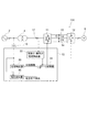
図5は、第2の実施形態に係る電力変換装置を模式的に表すブロック図である。
図5に表したように、電力変換装置110の制御ユニット15は、電圧検出器36をさらに有する。なお、上記第1の実施形態と機能・構成上実質的に同じものについては、同符号を付し、詳細な説明を省略する。
(Second Embodiment)
FIG. 5 is a block diagram schematically illustrating the power conversion apparatus according to the second embodiment.
As shown in FIG. 5, the
電圧検出器36には、電圧計16の検出結果が入力される。電圧検出器36は、電圧計16の検出結果を基に、交流電源2の三相交流電圧の一定値以上の低下を検出する。電圧検出器36の検出する電圧は、三相交流電圧の各相の相電圧でもよいし、三相交流電圧の各相の線間電圧でもよい。電圧の閾値は、例えば、交流電源2の三相交流電圧の定格電圧の20%〜30%である。電圧検出器36は、例えば、交流電源2の三相交流電圧の各相のいずれかが、定格電圧の20%以下になった場合に、一定値以上の低下を検出する。電圧検出器36は、三相交流電圧の一定値以上の低下を検出した場合、電圧低下の検出を表す電圧低下検出信号をゲート制御部34に入力する。
The detection result of the
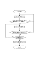
図6は、第2の実施形態に係る電力変換装置の動作を模式的に表すフローチャートである。
図6に表したように、ゲート制御部34は、第1変換器11をコンバータモードで動作させ、誘導電動機6を力行運転させている状態において、電圧検出器36によって電圧の低下が検出された場合、各スイッチング素子21をオフ状態にし、第1変換器11をコンバータモードからダイオード整流モードに切り替える。すなわち、この例において、ゲート制御部34は、交流電源2の三相交流電圧の各相のいずれかが一定値以上低下した場合に、交流電源2に不平衡事故が発生したと判断する。
FIG. 6 is a flowchart schematically showing the operation of the power conversion device according to the second embodiment.
As shown in FIG. 6, the
ゲート制御部34は、電圧検出器36によって三相交流電圧の低下が検出された後、三相交流電圧が一定値よりも大きい状態に復帰した場合、第1変換器11の動作をダイオード整流モードからコンバータモードに戻す。すなわち、ゲート制御部34は、複数のスイッチング素子21をオフ状態にした後、交流電源2の三相交流電圧が一定値よりも大きい状態に復帰した場合に、固定パルスパターン方式による複数のスイッチング素子21の制御を再開する。また、制御ユニット15は、ダイオード整流モードへの切り替えから所定時間経過した場合、第2変換器12の動作を停止させ、誘導電動機6の力行運転を停止する。
When the
交流電源2の不平衡事故の具合によっては、位相検出器30による異常の検出よりも先に、電圧検出器36によって異常が検出される場合がある。従って、本実施形態に係る電力変換装置110では、力行運転中に電圧低下が検出された場合に、第1変換器11をコンバータモードからダイオード整流モードに切り替える。これにより、例えば、交流電源2の不平衡事故をより適切に検出することができる。例えば、交流電源2の不平衡事故にともなう第1変換器11や第2変換器12などの故障をより適切に抑制することができる。
Depending on the condition of the unbalanced accident of the
このように、この例では、誘導電動機6の力行運転中において、位相検出器30の検出結果に基づく角速度、及び、電圧検出器36の検出結果に基づく電圧の少なくとも一方によって、交流電源2の不平衡事故を検出する。交流電源2の不平衡事故の検出は、上記第1の実施形態に示したように角速度のみで行ってもよいし、図6に表したように電圧のみで行ってもよい。
Thus, in this example, during the power running operation of the
なお、以上では変調率を1.2以上としたが、第1変換器11の電流定格に余裕が有る場合には、直流電圧Vdの低下に対し、電流を増加させることで必要な電力量を第2変換器12に供給することが可能である。つまり、変調率が1.2を下回る場合でも、第1変換器11がダイオード整流モードになった場合の直流電圧Vdの低下の程度の逆数の余裕を第1変換器11の電流定格に持たせれば、本発明の実施が可能である。
Although the modulation factor is 1.2 or more in the above, if the current rating of the
本発明のいくつかの実施形態を説明したが、これらの実施形態は、例として提示したものであり、発明の範囲を限定することは意図していない。これら新規な実施形態は、その他の様々な形態で実施されることが可能であり、発明の要旨を逸脱しない範囲で、種々の省略、置き換え、変更を行うことができる。これら実施形態やその変形は、発明の範囲や要旨に含まれるとともに、特許請求の範囲に記載された発明とその均等の範囲に含まれる。 Although several embodiments of the present invention have been described, these embodiments are presented by way of example and are not intended to limit the scope of the invention. These novel embodiments can be implemented in various other forms, and various omissions, replacements, and changes can be made without departing from the scope of the invention. These embodiments and modifications thereof are included in the scope and gist of the invention, and are included in the invention described in the claims and the equivalents thereof.
2…交流電源、 4…変圧器、 6…誘導電動機、 10、110…電力変換装置、 11…第1変換器、 12…第2変換器、 13、14…平滑コンデンサ、 15…制御ユニット、 16…電圧計、 17…電流計、 21…スイッチング素子、 22…整流素子、 23…整流素子、 30…位相検出器、 32…有効分・無効分電流検出器、 34…ゲート制御部、 36…電圧検出器
DESCRIPTION OF
Claims (7)
前記少なくとも3つの直流端子のそれぞれの間に設けられた複数の平滑コンデンサと、
前記少なくとも3つの直流端子に接続されるとともに、交流負荷に接続され、前記直流電圧を前記交流負荷に応じた第2三相交流電圧に変換し、前記第2三相交流電圧を前記交流負荷に供給する第2変換器と、
前記第1三相交流電圧の各相の電圧値を検出する電圧計と、
前記電圧計の検出結果を基に前記第1三相交流電圧の各相の位相を検出し、検出された前記位相を基に、前記第1三相交流電圧の線間電圧と前記直流電圧との変調率を1.2以上とした固定パルスパターン方式により、前記第1変換器の前記複数のスイッチング素子のスイッチングを制御するとともに、検出された前記位相を基に、前記第1三相交流電圧の各相の角速度を検出し、検出された前記角速度と角速度基準値との偏差が一定値以上である場合に、前記複数のスイッチング素子をオフ状態にする制御ユニットと、
を備えた電力変換装置。 A plurality of bridge-connected switching elements, a plurality of rectifying elements connected in antiparallel to each of the plurality of switching elements, three AC terminals, and at least three DC terminals. By switching the switching element, the first three-phase AC voltage input from the three AC terminals is converted into a DC voltage having at least three levels of a positive potential, a negative potential, and a neutral point potential, and the DC voltage is converted into the DC voltage. A first converter that outputs from at least three DC terminals;
A plurality of smoothing capacitors provided between each of the at least three DC terminals;
Connected to the at least three DC terminals and connected to an AC load, converts the DC voltage into a second three-phase AC voltage corresponding to the AC load, and converts the second three-phase AC voltage to the AC load. A second converter to supply;
A voltmeter for detecting a voltage value of each phase of the first three-phase AC voltage;
The phase of each phase of the first three-phase AC voltage is detected based on the detection result of the voltmeter, and the line voltage of the first three-phase AC voltage and the DC voltage are detected based on the detected phase. And controlling the switching of the plurality of switching elements of the first converter by a fixed pulse pattern method in which the modulation rate of the first converter is 1.2 or more, and based on the detected phase, the first three-phase AC voltage A control unit that detects the angular velocities of each of the phases and turns off the plurality of switching elements when a deviation between the detected angular velocities and the angular velocity reference value is a certain value or more;
The power converter provided with.
前記少なくとも3つの直流端子のそれぞれの間に設けられた複数の平滑コンデンサと、
前記少なくとも3つの直流端子に接続されるとともに、交流負荷に接続され、前記直流電圧を前記交流負荷に応じた第2三相交流電圧に変換し、前記第2三相交流電圧を前記交流負荷に供給する第2変換器と、
前記第1三相交流電圧の各相の電圧値を検出する電圧計と、
前記電圧計の検出結果を基に前記第1三相交流電圧の各相の位相を検出し、検出された前記位相を基に、前記第1三相交流電圧の線間電圧と前記直流電圧との変調率を1.2以上とした固定パルスパターン方式により、前記第1変換器の前記複数のスイッチング素子のスイッチングを制御するとともに、前記電圧計によって検出された前記第1三相交流電圧が一定値以上低下した場合に、前記複数のスイッチング素子をオフ状態にする制御ユニットと、
を備えた電力変換装置。 A plurality of bridge-connected switching elements, a plurality of rectifying elements connected in antiparallel to each of the plurality of switching elements, three AC terminals, and at least three DC terminals. By switching the switching element, the first three-phase AC voltage input from the three AC terminals is converted into a DC voltage having at least three levels of a positive potential, a negative potential, and a neutral point potential, and the DC voltage is converted into the DC voltage. A first converter that outputs from at least three DC terminals;
A plurality of smoothing capacitors provided between each of the at least three DC terminals;
Connected to the at least three DC terminals and connected to an AC load, converts the DC voltage into a second three-phase AC voltage corresponding to the AC load, and converts the second three-phase AC voltage to the AC load. A second converter to supply;
A voltmeter for detecting a voltage value of each phase of the first three-phase AC voltage;
The phase of each phase of the first three-phase AC voltage is detected based on the detection result of the voltmeter, and the line voltage of the first three-phase AC voltage and the DC voltage are detected based on the detected phase. The switching of the plurality of switching elements of the first converter is controlled by a fixed pulse pattern method with a modulation rate of 1.2 or more, and the first three-phase AC voltage detected by the voltmeter is constant. A control unit that turns off the plurality of switching elements when the value is reduced by more than a value;
The power converter provided with.
前記少なくとも3つの直流端子のそれぞれの間に設けられた複数の平滑コンデンサと、
前記少なくとも3つの直流端子に接続されるとともに、交流負荷に接続され、前記直流電圧を前記交流負荷に応じた第2三相交流電圧に変換し、前記第2三相交流電圧を前記交流負荷に供給する第2変換器と、
前記第1三相交流電圧の各相の電圧値を検出する電圧計と、
を備えた電力変換装置の制御方法であって、
前記電圧計の検出結果を基に前記第1三相交流電圧の各相の位相を検出する工程と、
検出された前記位相を基に、前記第1三相交流電圧の線間電圧と前記直流電圧との変調率を1.2以上とした固定パルスパターン方式により、前記第1変換器の前記複数のスイッチング素子のスイッチングを制御する工程と、
検出された前記位相を基に、前記第1三相交流電圧の各相の角速度を検出する工程と、
検出された前記角速度と角速度基準値との偏差が一定値以上である場合に、前記複数のスイッチング素子をオフ状態にする工程と、
を有する電力変換装置の制御方法。 A plurality of bridge-connected switching elements, a plurality of rectifying elements connected in antiparallel to each of the plurality of switching elements, three AC terminals, and at least three DC terminals. By switching the switching element, the first three-phase AC voltage input from the three AC terminals is converted into a DC voltage having at least three levels of a positive potential, a negative potential, and a neutral point potential, and the DC voltage is converted into the DC voltage. A first converter that outputs from at least three DC terminals;
A plurality of smoothing capacitors provided between each of the at least three DC terminals;
Connected to the at least three DC terminals and connected to an AC load, converts the DC voltage into a second three-phase AC voltage corresponding to the AC load, and converts the second three-phase AC voltage to the AC load. A second converter to supply;
A voltmeter for detecting a voltage value of each phase of the first three-phase AC voltage;
A method for controlling a power conversion device comprising:
Detecting the phase of each phase of the first three-phase AC voltage based on the detection result of the voltmeter;
Based on the detected phase, the fixed pulse pattern method in which the modulation rate between the line voltage of the first three-phase AC voltage and the DC voltage is 1.2 or more, the plurality of the first converters Controlling the switching of the switching element;
Detecting an angular velocity of each phase of the first three-phase AC voltage based on the detected phase;
A step of turning off the plurality of switching elements when a deviation between the detected angular velocity and an angular velocity reference value is a certain value or more;
A control method for a power conversion device having
前記少なくとも3つの直流端子のそれぞれの間に設けられた複数の平滑コンデンサと、
前記少なくとも3つの直流端子に接続されるとともに、交流負荷に接続され、前記直流電圧を前記交流負荷に応じた第2三相交流電圧に変換し、前記第2三相交流電圧を前記交流負荷に供給する第2変換器と、
前記第1三相交流電圧の各相の電圧値を検出する電圧計と、
を備えた電力変換装置の制御方法であって、
前記電圧計の検出結果を基に前記第1三相交流電圧の各相の位相を検出する工程と、
検出された前記位相を基に、前記第1三相交流電圧の線間電圧と前記直流電圧との変調率を1.2以上とした固定パルスパターン方式により、前記第1変換器の前記複数のスイッチング素子のスイッチングを制御する工程と、
前記電圧計によって検出された前記第1三相交流電圧が一定値以上低下した場合に、前記複数のスイッチング素子をオフ状態にする工程と、
を有する電力変換装置の制御方法。 A plurality of bridge-connected switching elements, a plurality of rectifying elements connected in antiparallel to each of the plurality of switching elements, three AC terminals, and at least three DC terminals. By switching the switching element, the first three-phase AC voltage input from the three AC terminals is converted into a DC voltage having at least three levels of a positive potential, a negative potential, and a neutral point potential, and the DC voltage is converted into the DC voltage. A first converter that outputs from at least three DC terminals;
A plurality of smoothing capacitors provided between each of the at least three DC terminals;
Connected to the at least three DC terminals and connected to an AC load, converts the DC voltage into a second three-phase AC voltage corresponding to the AC load, and converts the second three-phase AC voltage to the AC load. A second converter to supply;
A voltmeter for detecting a voltage value of each phase of the first three-phase AC voltage;
A method for controlling a power conversion device comprising:
Detecting the phase of each phase of the first three-phase AC voltage based on the detection result of the voltmeter;
Based on the detected phase, the fixed pulse pattern method in which the modulation rate between the line voltage of the first three-phase AC voltage and the DC voltage is 1.2 or more, the plurality of the first converters Controlling the switching of the switching element;
A step of turning off the plurality of switching elements when the first three-phase AC voltage detected by the voltmeter has decreased by a certain value or more;
A control method for a power conversion device having
Priority Applications (1)
| Application Number | Priority Date | Filing Date | Title |
|---|---|---|---|
| JP2016000443A JP6501266B2 (en) | 2016-01-05 | 2016-01-05 | Power converter and control method thereof |
Applications Claiming Priority (1)
| Application Number | Priority Date | Filing Date | Title |
|---|---|---|---|
| JP2016000443A JP6501266B2 (en) | 2016-01-05 | 2016-01-05 | Power converter and control method thereof |
Publications (2)
| Publication Number | Publication Date |
|---|---|
| JP2017123706A true JP2017123706A (en) | 2017-07-13 |
| JP6501266B2 JP6501266B2 (en) | 2019-04-17 |
Family
ID=59306048
Family Applications (1)
| Application Number | Title | Priority Date | Filing Date |
|---|---|---|---|
| JP2016000443A Active JP6501266B2 (en) | 2016-01-05 | 2016-01-05 | Power converter and control method thereof |
Country Status (1)
| Country | Link |
|---|---|
| JP (1) | JP6501266B2 (en) |
Cited By (1)
| Publication number | Priority date | Publication date | Assignee | Title |
|---|---|---|---|---|
| WO2021192288A1 (en) * | 2020-03-27 | 2021-09-30 | 三菱電機株式会社 | 3-level power conversion device and method for controlling intermediate potential of dc power supply unit |
Citations (7)
| Publication number | Priority date | Publication date | Assignee | Title |
|---|---|---|---|---|
| JPH03135374A (en) * | 1989-10-18 | 1991-06-10 | Yaskawa Electric Mfg Co Ltd | Control method of PWM converter |
| JPH0556682A (en) * | 1991-08-20 | 1993-03-05 | Hitachi Ltd | Power conversion system and control method thereof |
| JPH06205586A (en) * | 1992-12-28 | 1994-07-22 | Mitsubishi Electric Corp | Converter controller |
| JP2002078346A (en) * | 2000-08-29 | 2002-03-15 | Toshiba Corp | PWM control type power converter |
| JP2011193583A (en) * | 2010-03-12 | 2011-09-29 | Toshiba Mitsubishi-Electric Industrial System Corp | Three-level power converter |
| WO2012117642A1 (en) * | 2011-02-28 | 2012-09-07 | 三洋電機株式会社 | Electrical power conversion device, electrical power conversion system, and motor inverter |
| WO2015104886A1 (en) * | 2014-01-09 | 2015-07-16 | 東芝キヤリア株式会社 | Power conversion device |
-
2016
- 2016-01-05 JP JP2016000443A patent/JP6501266B2/en active Active
Patent Citations (7)
| Publication number | Priority date | Publication date | Assignee | Title |
|---|---|---|---|---|
| JPH03135374A (en) * | 1989-10-18 | 1991-06-10 | Yaskawa Electric Mfg Co Ltd | Control method of PWM converter |
| JPH0556682A (en) * | 1991-08-20 | 1993-03-05 | Hitachi Ltd | Power conversion system and control method thereof |
| JPH06205586A (en) * | 1992-12-28 | 1994-07-22 | Mitsubishi Electric Corp | Converter controller |
| JP2002078346A (en) * | 2000-08-29 | 2002-03-15 | Toshiba Corp | PWM control type power converter |
| JP2011193583A (en) * | 2010-03-12 | 2011-09-29 | Toshiba Mitsubishi-Electric Industrial System Corp | Three-level power converter |
| WO2012117642A1 (en) * | 2011-02-28 | 2012-09-07 | 三洋電機株式会社 | Electrical power conversion device, electrical power conversion system, and motor inverter |
| WO2015104886A1 (en) * | 2014-01-09 | 2015-07-16 | 東芝キヤリア株式会社 | Power conversion device |
Cited By (3)
| Publication number | Priority date | Publication date | Assignee | Title |
|---|---|---|---|---|
| WO2021192288A1 (en) * | 2020-03-27 | 2021-09-30 | 三菱電機株式会社 | 3-level power conversion device and method for controlling intermediate potential of dc power supply unit |
| JPWO2021192288A1 (en) * | 2020-03-27 | 2021-09-30 | ||
| JP7214040B2 (en) | 2020-03-27 | 2023-01-27 | 三菱電機株式会社 | 3-level power conversion device and method for controlling intermediate potential of DC power supply |
Also Published As
| Publication number | Publication date |
|---|---|
| JP6501266B2 (en) | 2019-04-17 |
Similar Documents
| Publication | Publication Date | Title |
|---|---|---|
| US10128741B2 (en) | Power conversion device | |
| US20200295595A1 (en) | Uninterruptible power supply device | |
| EP3609069B1 (en) | Converter system | |
| JP2016163513A (en) | Power conversion device | |
| JP5876846B2 (en) | Electric motor drive | |
| JP5734083B2 (en) | Power converter | |
| JP6501266B2 (en) | Power converter and control method thereof | |
| JP2012170318A (en) | Power converter and method of operation | |
| JP5490263B2 (en) | Power converter | |
| JPS6210109B2 (en) | ||
| JP5302905B2 (en) | Power converter | |
| JP2019176708A (en) | Power converter, heat generation system, load system, and electricity distribution-sending system | |
| JP5839374B1 (en) | Motor control device | |
| JP6690880B2 (en) | Power converter | |
| JP2012147571A (en) | Inverter apparatus and motor drive system | |
| JP2019054641A (en) | Power conversion equipment | |
| JP4893113B2 (en) | Control device for rectifier circuit | |
| KR100668104B1 (en) | Operation compensation device in case of switch failure of three-phase PWM rectifier | |
| JP2018196308A (en) | Series multiplex inverter device | |
| JP6516299B2 (en) | Power converter and control method thereof | |
| JP6512710B2 (en) | Power converter | |
| JP6093817B2 (en) | Motor control device | |
| JP2021048726A (en) | Power converter | |
| CN112534695A (en) | Method for controlling MMC | |
| JP4553079B2 (en) | AC / AC direct power converter |
Legal Events
| Date | Code | Title | Description |
|---|---|---|---|
| A621 | Written request for application examination |
Free format text: JAPANESE INTERMEDIATE CODE: A621 Effective date: 20180209 |
|
| A131 | Notification of reasons for refusal |
Free format text: JAPANESE INTERMEDIATE CODE: A131 Effective date: 20181113 |
|
| A977 | Report on retrieval |
Free format text: JAPANESE INTERMEDIATE CODE: A971007 Effective date: 20181114 |
|
| A521 | Request for written amendment filed |
Free format text: JAPANESE INTERMEDIATE CODE: A523 Effective date: 20190115 |
|
| TRDD | Decision of grant or rejection written | ||
| A01 | Written decision to grant a patent or to grant a registration (utility model) |
Free format text: JAPANESE INTERMEDIATE CODE: A01 Effective date: 20190313 |
|
| A61 | First payment of annual fees (during grant procedure) |
Free format text: JAPANESE INTERMEDIATE CODE: A61 Effective date: 20190313 |
|
| R150 | Certificate of patent or registration of utility model |
Ref document number: 6501266 Country of ref document: JP Free format text: JAPANESE INTERMEDIATE CODE: R150 |
|
| R250 | Receipt of annual fees |
Free format text: JAPANESE INTERMEDIATE CODE: R250 |
|
| R250 | Receipt of annual fees |
Free format text: JAPANESE INTERMEDIATE CODE: R250 |
|
| R250 | Receipt of annual fees |
Free format text: JAPANESE INTERMEDIATE CODE: R250 |
|
| R250 | Receipt of annual fees |
Free format text: JAPANESE INTERMEDIATE CODE: R250 |
|
| R250 | Receipt of annual fees |
Free format text: JAPANESE INTERMEDIATE CODE: R250 |