JP2017123990A - Ion wind type liquid evaporation device and air conditioner - Google Patents
Ion wind type liquid evaporation device and air conditioner Download PDFInfo
- Publication number
- JP2017123990A JP2017123990A JP2016004537A JP2016004537A JP2017123990A JP 2017123990 A JP2017123990 A JP 2017123990A JP 2016004537 A JP2016004537 A JP 2016004537A JP 2016004537 A JP2016004537 A JP 2016004537A JP 2017123990 A JP2017123990 A JP 2017123990A
- Authority
- JP
- Japan
- Prior art keywords
- ion wind
- ground electrode
- type liquid
- electrode portion
- unit
- Prior art date
- Legal status (The legal status is an assumption and is not a legal conclusion. Google has not performed a legal analysis and makes no representation as to the accuracy of the status listed.)
- Granted
Links
Images



Landscapes
- Devices For Blowing Cold Air, Devices For Blowing Warm Air, And Means For Preventing Water Condensation In Air Conditioning Units (AREA)
- Air Filters, Heat-Exchange Apparatuses, And Housings Of Air-Conditioning Units (AREA)
- Disinfection, Sterilisation Or Deodorisation Of Air (AREA)
Abstract
【課題】電界を安定させて空気のイオン化を効率良く行うと共に簡易な構成でイオン風を形成するイオン風式液体気化装置を提供する。【解決手段】本発明のイオン風式液体気化装置7は、導電性を有する機能液を保持可能に形成される接地電極部31と、接地電極部31に交差する方向に延設される針状の放電電極部33と、接地電極部31と放電電極部33との間に電圧を印加してコロナ放電を発生させる電源部21と、を備え、接地電極部31は、コロナ放電によって発生するイオン風を通過させる開口部34を有し、放電電極部33の先端部33aは、開口部34に対応して配置されると共に開口部34の縁部に非接触となる位置に配置されている。【選択図】図2An ion wind type liquid vaporizer that stabilizes an electric field to efficiently ionize air and forms an ion wind with a simple configuration is provided. An ionic wind type liquid vaporizer 7 according to the present invention includes a ground electrode portion 31 formed so as to be capable of holding a functional liquid having conductivity, and a needle shape extending in a direction intersecting the ground electrode portion 31. And a power supply unit 21 that generates a corona discharge by applying a voltage between the ground electrode unit 31 and the discharge electrode unit 33. The ground electrode unit 31 includes ions generated by corona discharge. An opening 34 for allowing the air to pass through is provided, and the distal end portion 33 a of the discharge electrode portion 33 is disposed corresponding to the opening 34 and is disposed at a position where it does not contact the edge of the opening 34. [Selection] Figure 2
Description
本発明は、コロナ放電によってイオン風を発生させるイオン風式液体気化装置および空気調和装置に関する。 The present invention relates to an ion wind type liquid vaporizer and an air conditioner that generate an ion wind by corona discharge.
従来から、放電針と接地電極との間に高電圧を印加してコロナ放電を発生させ、気体中のイオンを増加させる装置が知られている。 2. Description of the Related Art Conventionally, there has been known a device that applies a high voltage between a discharge needle and a ground electrode to generate corona discharge and increase ions in a gas.
例えば、特許文献1に記載のマイナスイオン発生器は、針状の負電極と間隔を隔てて配置された正電極をケース内に備えている。正電極は、マイナスイオンを通過させる複数の開孔部を有している。芳香性物質は、導電性材料から成る正電極に含浸、練り込み等によって固定化されている。直流電源から両電極間に負の高電圧が印加されると、コロナ放電に伴ってマイナスイオンが発生すると共に正電極内の芳香分子が放出される。そして、マイナスイオンと芳香分子とは、ファン(送風機)を作動させることでケース外に送り出される。
For example, the negative ion generator described in
また、例えば、特許文献2に記載の空気清浄装置は、放電電極と対向電極を有する放電部に電源部から電圧を印加して放電回路を形成してコロナ放電させる放電ユニットを備えている。針状の放電電極は、平板状の対向電極に対して非接触で直交する姿勢で配置されている。また、放電電極の先端部は、対向電極を突出している。この空気清浄装置は、放電電極の側面に向けて空気を送る送風手段(ファン)と、放電ユニットに対して送風方向下流側に配置される静電霧化ユニットと、を備えている。
Further, for example, the air cleaning device described in
しかしながら、特許文献1に記載のマイナスイオン発生器では、コロナ放電が1本の負電極と正電極の複数の開孔部との間で生じる。分散された位置で発生するコロナ放電は弱くなるため、空間に放出される芳香分子の量が少なくなるという問題があった。また、大部分の開孔部は負電極に対向していないため、各々の開孔部において電界にばらつきが生じていた。このため、上記マイナスイオン発生器は、空気のイオン化を効率良く行うことができない虞があった。また、上記マイナスイオン発生器は、正電極に固定化された芳香性物質を消費し切った後に芳香性物質を補給することについて考慮されていなかった。つまり、永続的な芳香分子の放出を担保できない虞があった。さらに、マイナスイオンおよび芳香分子の放出にファンが必要であるため、マイナスイオン発生器の大型化や製造コストの増加という問題もあった。
However, in the negative ion generator described in
また、特許文献2に記載の空気清浄装置では、コロナ放電に伴うイオン風の向きと、送風手段による送風の向きとが交差しているため、イオン風を効率良く装置の外部に送り出すことができなかった。また、静電霧化ユニットが送風方向下流側に配置されているため、加湿効率が悪化していた。さらに、イオン化した空気の放出にファンが必要であるため、装置の大型化や製造コストの増加という問題もあった。
Further, in the air cleaning device described in
本発明は、上記した課題を解決するため、電界を安定させて空気のイオン化を効率良く行うと共に簡易な構成でイオン風を形成するイオン風式液体気化装置および空気調和装置を提供する。 In order to solve the above-described problems, the present invention provides an ion wind type liquid vaporizer and an air conditioner that stabilize an electric field, efficiently ionize air, and form an ion wind with a simple configuration.
上記した目的を達成するため、本発明の第1のイオン風式液体気化装置は、導電性を有する機能液を保持可能に形成される接地電極部と、前記接地電極部に交差する方向に延設される針状の放電電極部と、前記接地電極部と前記放電電極部との間に電圧を印加してコロナ放電を発生させる電源部と、を備え、前記接地電極部は、前記コロナ放電によって発生するイオン風を通過させる開口部を有し、前記放電電極部の先端部は、前記開口部に対応して配置されると共に前記開口部の縁部に非接触となる位置に配置されている。 In order to achieve the above object, a first ionic wind type liquid vaporizer according to the present invention includes a ground electrode portion formed so as to be able to hold a functional liquid having conductivity, and a direction extending across the ground electrode portion. A needle-like discharge electrode portion provided, and a power supply portion that generates a corona discharge by applying a voltage between the ground electrode portion and the discharge electrode portion, and the ground electrode portion includes the corona discharge. The discharge electrode portion has an opening that passes through the opening and is disposed at a position that is not in contact with an edge of the opening. Yes.
本発明の第1のイオン風式液体気化装置によれば、コロナ放電によってイオンが発生すると共に、放電電極部の先端部から基端部に向けてイオン風が発生する。接地電極部に含まれた機能液は、開口部を通過するイオン風によって気化する。ここで、例えば、機能液が芳香、殺菌および消臭等の機能性成分を含む場合、この機能性成分は、水分と共にイオン風に乗って流通方向下流側に運ばれる。これにより、イオン風の流通方向下流側の空間が、加湿されると共に機能性成分の作用(例えば、芳香付与、殺菌、消臭等)を受けることができる。また、水分や機能性成分は、イオン風によって搬送されるため、送風ファン等を省略することができ、装置の製造コストや消費電力等を低減することができる。さらに、イオン風に含まれる塵埃やウィルス等は、コロナ放電によって発生する電界(電場)によって接地電極部の開口部の縁部に捕集される。これにより、空気を清浄化することができる。 According to the first ion wind type liquid vaporizer of the present invention, ions are generated by corona discharge, and ion wind is generated from the distal end portion of the discharge electrode portion toward the proximal end portion. The functional liquid contained in the ground electrode portion is vaporized by the ion wind passing through the opening. Here, for example, when the functional liquid contains functional components such as aroma, sterilization, and deodorization, the functional components are carried along with the moisture on the ionic wind and are carried downstream in the distribution direction. Thereby, the space on the downstream side in the circulation direction of the ionic wind can be humidified and receive the action of functional components (for example, imparting aroma, sterilization, deodorization, etc.). Further, since moisture and functional components are conveyed by ion wind, a blower fan or the like can be omitted, and the manufacturing cost and power consumption of the apparatus can be reduced. Furthermore, dust, viruses, and the like contained in the ion wind are collected at the edge of the opening of the ground electrode portion by an electric field (electric field) generated by corona discharge. Thereby, air can be purified.
本発明の第2のイオン風式液体気化装置は、上記した本発明の第1のイオン風式液体気化装置において、前記放電電極部の先端部は、前記イオン風の流通方向下流側から上流側に向けて前記開口部を貫通している。 The second ion wind type liquid vaporizer of the present invention is the above-described first ion wind type liquid vaporizer of the present invention, wherein the tip of the discharge electrode portion is upstream from the downstream side in the flow direction of the ion wind. The opening is penetrated toward the surface.
本発明の第2のイオン風式液体気化装置によれば、放電電極部は開口部を貫通しているため、コロナ放電を発生させる電気力は、主に、放電電極部の先端部と開口部の上流側の縁部との間に発生する(電気力線が密集する)。また、電気力は、放電電極部の胴部(先端部から基端側に延びる部分)と開口部の内周面との間や、放電電極部の胴部と開口部の下流側縁部との間にも発生する。したがって、機能液は、開口部の内周面を含む表裏両側の縁部から気化する。これにより、機能液の気化効率を向上させることができる。 According to the second ion wind type liquid vaporizer of the present invention, since the discharge electrode portion passes through the opening, the electric force for generating corona discharge is mainly generated at the tip and the opening of the discharge electrode portion. It occurs between the edge of the upstream side of (the electric lines of force are dense). In addition, the electric force is generated between the body of the discharge electrode part (the part extending from the distal end part to the base end side) and the inner peripheral surface of the opening, or between the body of the discharge electrode part and the downstream edge of the opening. It also occurs during. Therefore, the functional liquid is vaporized from the edge portions on both the front and back sides including the inner peripheral surface of the opening. Thereby, the vaporization efficiency of a functional liquid can be improved.
本発明の第3のイオン風式液体気化装置は、上記した本発明の第1または第2のイオン風式液体気化装置において、前記接地電極部は、電気絶縁性を有する多孔質材料によって形成されている。 According to a third ion wind type liquid vaporizer of the present invention, in the first or second ion wind type liquid vaporizer of the present invention described above, the ground electrode portion is formed of a porous material having electrical insulation. ing.
本発明の第3のイオン風式液体気化装置によれば、接地電極部は、多孔質材料で形成されているため、機能液を適切に保持することができる。ここで、仮に、全ての機能液が気化してしまった場合、接地電極部は電気絶縁性を有しているため、コロナ放電が停止する。すなわち、機能液を完全に消費したことに起因して、コロナ放電が自動的に禁止される。これにより、機能液の枯渇時における装置の安全性を担保することができる。また、機能液の枯渇を検知する装置や電源部を停止させる装置を省略することができる。 According to the third ion wind type liquid vaporizer of the present invention, since the ground electrode portion is formed of the porous material, the functional liquid can be appropriately held. Here, if all the functional liquid is vaporized, the corona discharge stops because the ground electrode portion has electrical insulation. That is, corona discharge is automatically prohibited due to the complete consumption of the functional fluid. Thereby, the safety | security of the apparatus at the time of depletion of a functional liquid can be ensured. Further, a device for detecting the depletion of the functional liquid and a device for stopping the power supply unit can be omitted.
本発明の第4のイオン風式液体気化装置は、上記した本発明の第1ないし第3のいずれかのイオン風式液体気化装置において、前記電源部を制御して前記印加する電圧を調整する制御部を更に備えている。 According to a fourth ion wind type liquid vaporizer of the present invention, in the ion wind type liquid vaporizer of any one of the first to third aspects of the present invention described above, the power supply unit is controlled to adjust the applied voltage. A control unit is further provided.
本発明の第4のイオン風式液体気化装置によれば、制御部が電源部から2つの電極部間に印加する電圧(印加電圧)を調整することで、イオン風の流速(風速)を変更することができる。イオン風の強弱を調整することで、機能液の気化速度を調整することができる。これにより、印加電圧を制御するだけで、加湿量(水分の供給量)を容易に制御することができる。 According to the fourth ion wind type liquid vaporizer of the present invention, the flow rate (wind speed) of the ion wind is changed by adjusting the voltage (applied voltage) applied by the control unit between the two electrode units from the power supply unit. can do. By adjusting the strength of the ionic wind, the vaporization rate of the functional liquid can be adjusted. Thereby, the humidification amount (water supply amount) can be easily controlled only by controlling the applied voltage.
本発明の第5のイオン風式液体気化装置は、上記した本発明の第1ないし第4のいずれかのイオン風式液体気化装置において、前記接地電極部に補給する前記機能液を貯留可能に構成される供給部を更に含んでいる。 According to a fifth ion wind type liquid vaporizer of the present invention, in any of the above-described first to fourth ion wind type liquid vaporizers, the functional liquid to be supplied to the ground electrode portion can be stored. It further includes a supply section configured.
本発明の第5のイオン風式液体気化装置によれば、機能液は供給部から接地電極部に供給されるため、イオン風式液体気化装置は長期間に亘り継続的に稼動することができる。また、例えば、接地電極部に保持させる機能液の機能性成分を変更したい場合、供給部に貯留させる機能液を変更すればよい。このように、機能液の機能性成分を容易に変更することができる。 According to the fifth ion wind type liquid vaporizer of the present invention, since the functional liquid is supplied from the supply unit to the ground electrode unit, the ion wind type liquid vaporizer can be continuously operated over a long period of time. . Further, for example, when it is desired to change the functional component of the functional liquid held in the ground electrode part, the functional liquid stored in the supply part may be changed. In this way, the functional component of the functional liquid can be easily changed.
本発明の第6のイオン風式液体気化装置は、上記した本発明の第1ないし第5のいずれかのイオン風式液体気化装置において、紫外線を前記接地電極部に照射する紫外線照射部を更に備えている。 A sixth ion wind type liquid vaporizer according to the present invention is the above-described ion wind type liquid vaporizer according to any one of the first to fifth aspects of the present invention, further comprising an ultraviolet irradiation unit for irradiating the ground electrode part with ultraviolet rays. I have.
本発明の第6のイオン風式液体気化装置によれば、高電圧と紫外線照射部から照射された紫外線とによって接地電極部に捕集されたウィルスを有効に不活性化することができる。 According to the sixth ion wind type liquid vaporizer of the present invention, it is possible to effectively inactivate the virus collected in the ground electrode portion by the high voltage and the ultraviolet rays irradiated from the ultraviolet irradiation portion.
本発明の第7のイオン風式液体気化装置は、上記した本発明の第1ないし第6のいずれかのイオン風式液体気化装置において、前記接地電極部は、塩素系成分またはビタミンCを含む前記機能液を保持する。 According to a seventh ionic wind type liquid vaporizer of the present invention, in any one of the first to sixth ionic wind type liquid vaporizers of the present invention described above, the ground electrode portion includes a chlorine component or vitamin C. The functional liquid is retained.
本発明の第7のイオン風式液体気化装置によれば、機能液の機能性成分としての塩素系成分がウィルスを不活性化する。機能液の塩素系成分と高電圧(および紫外線照射部)との組み合わせによって、より有効なウィルスの不活性効果を発揮することができる。機能液の機能性成分としてのビタミンCは、コロナ放電時におけるオゾンの発生を抑制する。 According to the seventh ion wind type liquid vaporizer of the present invention, the chlorine-based component as the functional component of the functional liquid inactivates the virus. By combining the chlorine component of the functional liquid and the high voltage (and the ultraviolet irradiation section), a more effective virus inactivation effect can be exhibited. Vitamin C as a functional component of the functional fluid suppresses the generation of ozone during corona discharge.
本発明の空気調和装置は、第1ないし第7のいずれかに記載のイオン風式液体気化装置を備える空気調和装置であって、前記イオン風式液体気化装置は、吸気口と排気口とを有する筐体の内部に設けられ、前記吸気口から前記筐体内に吸い込んだ空気にイオンを含ませた前記イオン風を発生させ、前記イオン風を前記排気口から前記筐体外に吹き出す。 An air conditioner of the present invention is an air conditioner including the ion wind type liquid vaporizer according to any one of the first to seventh aspects, wherein the ion wind type liquid vaporizer includes an intake port and an exhaust port. The ion wind that is provided inside the housing having the air and sucked into the housing from the intake port is generated, and the ion wind is blown out of the housing through the exhaust port.
本発明の空気調和装置によれば、コロナ放電に伴って発生したイオン風は、開口部を通過する際に接地電極部に含まれた機能液を気化する。これにより、機能液の機能性成分(例えば、芳香、殺菌、消臭等の成分)を水分と共にイオン風に乗せて流通方向下流側の空間に運ぶことができる。また、送風ファン等を用いることなく、水分や機能性成分をイオン風に乗せて搬送することができるため、装置の製造コストや消費電力等を低減することができる。さらに、電界の発生によって、塵埃やウィルス等を接地電極部に捕集することができる。 According to the air conditioner of the present invention, the ion wind generated along with the corona discharge vaporizes the functional liquid contained in the ground electrode portion when passing through the opening. Thereby, the functional components (for example, components such as aroma, sterilization, and deodorant) of the functional liquid can be carried on the ion wind together with moisture and carried to the space downstream in the distribution direction. Further, since moisture and functional components can be transported on ion wind without using a blower fan or the like, the manufacturing cost and power consumption of the apparatus can be reduced. Furthermore, dust, viruses, and the like can be collected on the ground electrode portion by the generation of the electric field.
本発明によれば、電界を安定させて空気のイオン化を効率良く行うことができる。また、送風ファン等を省略し、簡易な構成でイオン風を形成することができる。 According to the present invention, the electric field can be stabilized and ionization of air can be performed efficiently. Moreover, an air blower etc. can be abbreviate | omitted and ion wind can be formed with a simple structure.
以下、本発明に係るイオン風式液体気化装置を備える空気調和装置の実施の形態について添付した図面を参照しながら説明する。この実施の形態は本発明の好適な具体例であって、技術的に好ましい種々の限定を付している場合もあるが、本発明の技術範囲は、特に本発明を限定する記載がない限りこれらの態様に限定されるものではない。 DESCRIPTION OF EMBODIMENTS Hereinafter, embodiments of an air conditioner including an ionic wind type liquid vaporizer according to the present invention will be described with reference to the accompanying drawings. This embodiment is a preferred specific example of the present invention, and may have various technically preferable limitations. However, the technical scope of the present invention is not particularly limited unless otherwise specified. However, the present invention is not limited to these embodiments.
図1を参照して、本実施形態に係る空気調和装置1の全体構成について説明する。図1は空気調和装置1の内部構造を模式的に示す断面図である。なお、以下の説明では、便宜上、各図に矢印で示すように各方向を設定している。
With reference to FIG. 1, the whole structure of the
空気調和装置1は、外部から吸い込んだ空気を清浄化し、清浄化した空気をイオンと共に外部に放出するものである。空気調和装置1は、吸気口3と排気口4とを有する略直方体状の筐体2を備えている。吸気口3は筐体2の前面下部に形成され、排気口4は筐体2の上面に形成されている。吸気口3は、外部の空気を筐体2内に取り込むために設けられている。吸気口3の内側には、空気中の塵埃(比較的大きな粒子)を捕集するフィルター5が設けられている。排気口4は、筐体2内の空気を外部に排出するために設けられている。
The
空気調和装置1は、操作部6と、イオン風式液体気化装置7と、を備えている。操作部6は、筐体2の前面に設けられている。イオン風式液体気化装置7は、筐体2の内部に設けられている。
The
操作部6は、フロントパネル10と、表示部11と、スイッチ12と、を含んでいる。フロントパネル10は、筐体2の前面上部に固定されている。表示部11およびスイッチ12は、フロントパネル10に組み込まれている。表示部11は、例えば、液晶画面(タッチパネル)や作動状態を示すLED等を含んでいる。スイッチ12は、例えば、各種設定用のスイッチや電源部21(後述する)をON/OFFさせる運転スイッチを含んでいる。
The
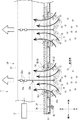
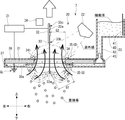
次に、図1ないし図5を参照して、イオン風式液体気化装置7について説明する。図2はイオン風式液体気化装置7を模式的に示す断面図である。図3は、図1のIII−III断面図である。図4はイオン風式液体気化装置7の供給部23を模式的に示す断面図である。図5はイオン風式液体気化装置7の制御部25を示すブロック図である。
Next, the ion wind type liquid vaporizer 7 will be described with reference to FIGS. 1 to 5. FIG. 2 is a sectional view schematically showing the ion wind type liquid vaporizer 7. 3 is a cross-sectional view taken along the line III-III in FIG. FIG. 4 is a cross-sectional view schematically showing the
イオン風式液体気化装置7は、吸気口3から筐体2内に吸い込んだ空気にマイナスイオンを含ませたイオン風を発生させ、イオン風を排気口4から筐体2外に吹き出す。なお、イオン風式液体気化装置7は、コロナ放電によってイオン風を発生させる。なお、以下の説明において、「流通方向」とは、イオン風が流れる方向を指す。また、「上流」および「下流」並びにこれらに類する用語は、イオン風の流通方向における「上流」および「下流」並びにこれらに類する概念を指す。
The ion wind type liquid vaporizer 7 generates an ion wind in which negative ions are included in the air sucked into the
図1に示すように、イオン風式液体気化装置7は、荷電部20と、電源部21と、紫外線照射部22と、供給部23と、湿度芳香検知部24と、制御部25と、を含んでいる。
As shown in FIG. 1, the ionic wind type liquid vaporizer 7 includes a charging
荷電部20は、枠体30と、接地電極部31と、支持基板32と、複数(例えば、図1では3本)の放電電極部33と、を含んでいる。枠体30は、筐体2の内部フレーム(図示せず)に支持されている。接地電極部31および複数の支持基板32は、それぞれ、枠体30の内側に支持されている。複数の放電電極部33は、それぞれ、支持基板32に片持ちで支持されている。
The charging
枠体30は、平面から見て略矩形環状(枠状)に形成されている。枠体30は、電気絶縁性を有する碍子(図示せず)を介して内部フレームに支持されている。つまり、枠体30は、筐体2に対して電気的に絶縁された状態で支持されている。枠体30には、電源部21を接続するための給電部材(図示せず)が形成されている。
The
図2および図3に示すように、接地電極部31は、平面から見て略矩形を成す平板状に形成されている。接地電極部31は、筐体2の内部空間を上下方向に2分割するように枠体30の内側に配置されている(図1参照)。接地電極部31は、イオン風の流通方向(上下方向)に交差(直交)する向きで枠体30に固定されている。接地電極部31を略水平に配置することで、筐体2の高さを低く抑えることができる。これにより、空気調和装置1(筐体2)の小型化を図ることができる。
As shown in FIGS. 2 and 3, the
また、接地電極部31は、アース線GL(基準電位点)に電気的に接続されている。接地電極部31は、電気絶縁性を有する多孔質材料によって形成されている。例えば、接地電極部31は、発泡ウレタン等の比較的硬いスポンジや、ゼオライト等によって形成されている。接地電極部31は、導電性を有する機能液を保持可能に形成されている。すなわち、多孔質体から成る接地電極部31は、孔内の空気を機能液に置き換えることで機能液を保持(吸収)する。
The
ここで、機能液は、水(純水を除く)または水に芳香、殺菌および消臭等の機能性成分を混合して構成されている。また、機能液は、機能性成分として塩素系成分とビタミンCと芳香成分とのうち少なくとも1つを含んでいる。機能液は、水分を含むことで導電性を有している。したがって、接地電極部31は、機能液を保持した状態で電極として機能する。なお、塩素系成分とは、一例として、人体への安全性や殺菌作用を考慮して塩(食塩(NaCl))であることが好ましい。芳香成分とは、一例として、香りのするアロマオイルであることが好ましい。
Here, the functional liquid is configured by mixing functional components such as aroma, sterilization, and deodorization in water (excluding pure water) or water. Further, the functional liquid contains at least one of a chlorine-based component, vitamin C, and an aromatic component as a functional component. The functional liquid has conductivity by containing moisture. Therefore, the
接地電極部31は、コロナ放電によって発生するイオン風を通過させる複数(例えば、図1では3つ)の開口部34を有している。各開口部34は、平面から見て円形状に形成されている。各開口部34は、上下方向に2分割された筐体2の内部空間を連通させるように接地電極部31に穿設されている。各開口部34は、例えば、直径15mm程度に設定されている。複数の開口部34は、前後方向に所定間隔で並設されている。
The
接地電極部31は、電気絶縁性を有する絶縁カバー36で覆われている。絶縁カバー36は、各開口部34の縁部35を除く接地電極部31全体を覆っている。つまり、各開口部34の縁部35は、絶縁カバー36から露出している。各縁部35の露出面積は、流通方向下流側よりも上流側で広くなっている。すなわち、各開口部34の上下両側の縁部35のうち、下側の縁部35は、上側の縁部35よりも絶縁カバー36から大きく露出している。なお、以下の説明では、各開口部34の下側の縁部35を「上流縁部35U」と呼び、上側の縁部35を「下流縁部35D」と呼ぶこととする。また、上下両側の縁部35に共通する説明では、単に縁部35と呼ぶこととする。
The
下側の絶縁カバー36は、接地電極部31の下面から下方に離間して設けられている。絶縁カバー36は、各開口部34の上流縁部35Uに当接するように折り曲げられた複数の屈曲部36aを有している。複数の屈曲部36aによって、接地電極部31の下面と絶縁カバー36との間に空間が形成されている。詳細は後述するが、この空間は、機能液を一時的に貯留するための液体貯留部37として用いられる。
The lower insulating
図1および図2に示すように、支持基板32は、導電性を有する材料で、側面から見て前後方向に長い平板状に形成されている。支持基板32は、接地電極部31の上方(流通方向下流側)に配置されている。支持基板32は、一列に並んだ複数の開口部34に沿って配置されている。各支持基板32は、スプリング(図示せず)を介して枠体30に支持されている。
As shown in FIGS. 1 and 2, the
図3に示すように、支持基板32の両側面は、正面から見て接地電極部31に直交している。つまり、支持基板32は、イオン風の流通方向と平行に配置されている。図2および図3に示すように、支持基板32の一側面には、上下一対のカシメ部32aが前後方向に複数(例えば、3箇所(図1参照))並設されている。複数の上下一対のカシメ部32aは、開口部34に対応して形成されている。なお、支持基板32は、イオン風の流通を妨げないように配置されていれば、接地電極部31に直交していなくてもよい。
As shown in FIG. 3, both side surfaces of the
図1ないし図3に示すように、複数の放電電極部33は、開口部34に対応して設けられている。なお、複数の放電電極部33は同様の形状であるため、以下、1つの放電電極部33について説明する。
As shown in FIGS. 1 to 3, the plurality of
放電電極部33は、例えば、JIS60種合金(6%Al+4%V+90%Ti)等のチタン合金(所謂64チタン)で形成されている。放電電極部33は、例えば、直径0.5mm〜0.6mmの細線状または針状に形成されている。放電電極部33の先端部33a(下端部)は、円錐状に研磨加工されている。放電電極部33の先端部33aは、例えば、直径0.05mm〜0.15mmに形成されている。放電電極部33の材料として靭性に優れた64チタンを採用することで、放電電極部33と支持基板32との接合部の破断を抑制することができ、放電電極部33の耐久性を高めることができる。
The
図2および図3に示すように、放電電極部33は、上下一対のカシメ部32aにかしめられ、支持基板32に接合固定されている。放電電極部33の基端部33c(上端部)が、上下一対のカシメ部32aに片持ちで支持されている。放電電極部33は、カシメ部32aから接地電極部31側(支持基板32よりも流通方向上流側)に延びている。つまり、放電電極部33は、接地電極部31に交差(直交)する方向に延設されている。放電電極部33の先端部33aは、開口部34に対応して配置されると共に開口部34の縁部35に非接触となる位置に配置されている。
As shown in FIGS. 2 and 3, the
放電電極部33の先端部33aは、流通方向下流側から上流側に向けて開口部34を貫通している。図3に示すように、放電電極部33の先端部33aと開口部34の上流縁部35Uとの間隔(第1放電ギャップG1)は一定に維持されている。また、放電電極部33の胴部33b(先端部33aと基端部33cとの中間部分)と開口部34の下流縁部35D(内周面34i)との間隔(第2放電ギャップG2)は一定に維持されている。本実施形態では、例えば、第1および第2放電ギャップG1,G2は、それぞれ、10mm〜20mm程度の範囲で設定される。なお、第1および第2放電ギャップG1,G2は、それぞれ、放電電極部33の太さ、開口部34の大きさ、印加電圧の大きさ、放電電極部33や開口部34の縁部35に対する汚れの堆積量等を考慮して設定されることが好ましい。
The
以上のような放電電極部33を用いることで、オゾンの発生量を著しく低下することができる。また、このような放電電極部33を採用することで、優れた加工性と安定した放電とを担保することができる。さらに、放電電極部33の磨耗量が抑制され、長寿命化を図ることができる。されに、強いコロナ放電が発生する放電電極部33の先端部33aは、汚れにくくなるため、安定した放電を継続的に行うことができる。
By using the
電源部21は、交流の商用電源(図示せず)に接続されている。また、電源部21は、接地電極部31と枠体30(給電部材)とに接続されている。電源部21は、枠体30および支持基板32を介して放電電極部33に電気的に接続されている(図2および図3参照)。電源部21は、交流電流を直流電流に変換し、操作部6およびイオン風式液体気化装置7の各構成に電力を供給する。また、電源部21は、数kV〜数十kVの高電圧を生成する。なお、本実施形態では、放電電極部33が負極になっている(マイナス荷電方式)。なお、筐体2内には、電源部21を冷却するための電源冷却用ファン21a(図5参照)が設けられている。
The
図1および図3に示すように、紫外線照射部22は、接地電極部31の上方(流通方向下流側)に配置されている。紫外線照射部22は、紫外線を接地電極部31の各開口部34およびその縁部35に照射するように設けられている。紫外線照射部22は、殺菌に有効とされる波長100〜280nmの短波紫外線(区分UV−C)を発するランプ(図示せず)を採用している。
As shown in FIGS. 1 and 3, the
図3および図4に示すように、供給部23は、貯留タンク40と、水位センサー41と、接続配管42と、調整フロート43と、を含んでいる。供給部23は、接地電極部31に補給する機能液を貯留可能に構成されている。
As shown in FIGS. 3 and 4, the
貯留タンク40は、接地電極部31の上方(流通方向下流側)に配置されている。貯留タンク40は、筐体2の後部に配置されている、貯留タンク40の内部には、機能液が貯留されている。なお、筐体2の後部には、カバー(図示せず)が開閉可能に設けられ、カバーを開放することで、貯留タンク40に機能液を補充することができるように構成されている。
The
水位センサー41は、貯留タンク40内の機能液の貯留量(上限/下限)を検知する。水位センサー41は、例えば、機能液に接触することで導通可能な2つの電極(図示せず)を有している。貯留タンク40内に十分な機能液が存在する場合、2つの電極間が導通する。貯留タンク40内の機能液が減少してくると、2つの電極間が導通しなくなる。つまり、水位センサー41は、2つの電極間の導通の有無を検知することで、機能液の貯留量を検知する。
The
接続配管42は、貯留タンク40と接地電極部31の絶縁カバー36との間に接続されている。接続配管42の上端部(上流側)は、貯留タンク40の内部に連通している。接続配管42の下端部(下流側)は、接地電極部31の下側に形成された液体貯留部37に連通している。
The
調整フロート43は、接続配管42の下端部(下流端部)に設けられている。調整フロート43は、液体貯留部37内に貯留された機能液に浮いている。調整フロート43は、接続配管42の下端面に密接可能なテーパー面43aを有している。
The
図4に示すように、液体貯留部37における機能液の水面が規定の高さよりも低い場合、調整フロート43も下がる。したがって、調整フロート43のテーパー面43aは、接続配管42の下端面から下方に離間する。これにより、貯留タンク40に貯留された機能液は、接続配管42を通って液体貯留部37に流入する。図3に示すように、液体貯留部37における機能液の水面が上昇すると、調整フロート43も上昇する。すると、調整フロート43のテーパー面43aは、接続配管42の下端面に密着し、接続配管42を閉塞する。これにより、液体貯留部37に対する機能液の流入が停止される。以上のように、調整フロート43は、液体貯留部37に対する機能液の供給量を調整する。なお、液体貯留部37において機能液の水面の規定の高さとは、接地電極部31が機能液に浸る状態を指している。この状態で、液体貯留部37内の機能液は、接地電極部31に吸収される。
As shown in FIG. 4, when the water level of the functional liquid in the
図1および図3に示すように、湿度芳香検知部24は、筐体2内の前側上方に配置されている。湿度芳香検知部24は、筐体2の内部の湿度を検知すると共に、気化した機能液に含まれる芳香成分の濃度を検知する。
As shown in FIGS. 1 and 3, the humidity
図5に示すように、制御部25は、CPU50と、記憶部51と、バス52と、インターフェース部53と、を含んでいる。制御部25は、空気調和装置1の各構成要素を制御する。
As shown in FIG. 5, the
CPU50(Central Processing Unit)は、記憶部51に記憶されたデータやプロクラム等に従って様々な演算処理を実行する。CPU50は、操作部6を介して入力された情報を受信して記憶部51に一時記憶させる。記憶部51は、空気調和装置1の制御(空気調和処理)に必要なデータやプログラム等を記憶している。バス52は、CPU50、記憶部51およびインターフェース部53を電気的に接続させる。インターフェース部53には、表示部11、スイッチ12、紫外線照射部22、水位センサー41、電源部21、電源冷却用ファン21a、湿度芳香検知部24等が電気的に接続されている。これにより、CPU50は、インターフェース部53に接続された各構成要素と各種制御信号の送受信を行うことができる。
A CPU 50 (Central Processing Unit) executes various arithmetic processes according to data, programs, and the like stored in the
ここで、図6および図7を参照して、空気調和装置1(イオン風式液体気化装置7)の作用(空気調和処理)について説明する。図6は空気調和装置1の空気調和処理を説明するフローチャートである。図7はイオン風式液体気化装置7の作用を示す斜視図である。
Here, with reference to FIG. 6 and FIG. 7, the effect | action (air conditioning process) of the air conditioning apparatus 1 (ionic wind type liquid vaporizer 7) is demonstrated. FIG. 6 is a flowchart illustrating the air conditioning process of the
図6に示すように、制御部25(CPU50)は、操作部6のスイッチ12(運転スイッチ)がONされたか否かを判定する(S1)。制御部25は、スイッチ12がONされるまでステップS1を繰り返す(S1で「NO」)。
As shown in FIG. 6, the control unit 25 (CPU 50) determines whether or not the switch 12 (operation switch) of the
空気調和処理を行う場合、ユーザーは、スイッチ12をONにする。すると、制御部25(CPU50)は、スイッチ12がONにされたことを検知する(S1で「YES」)。続いて、制御部25は、水位センサー41の検知結果を受信し、貯留タンク40内に規定範囲内(下限以上上限以下)の機能液が貯留しているか否かを判定する(S2)。なお、「規定範囲」とは、例えば、水位センサー41の2つの電極間が導通している状態を示す。水位センサー41の検知結果が規定範囲内であった場合(S2で「YES」)、電源部21は、制御部25に制御されて、接地電極部31と放電電極部33との間に高電圧を印加する(S3)。
When performing the air conditioning process, the user turns on the
一方、水位センサー41の検知結果が規定範囲外であった場合(S2で「NO」)、制御部25は、エラーを示す情報を表示部11に出力(表示)させる(S11)。なお、例えば、ユーザーに機能液を貯留タンク40に補充するように促すエラー情報が、表示部11に表示されることが好ましい。制御部25は、再び水位センサー41の検知結果を受信し、貯留タンク40内の水位(貯留量)が規定範囲内であるか否かを判定する(S12)。以降、制御部25は、貯留タンク40内の水位が規定範囲内であることを示す検知結果を受信するまでステップS12の判定を繰り返す(S12で「NO」)。一方、水位センサー41の検知結果が規定範囲内であった場合(S12で「YES」)、制御部25は、エラー出力を停止(S13)し、電源部21を制御して高電圧を出力させる(S3)。
On the other hand, when the detection result of the
ここで、機能液を保持した接地電極部31と各放電電極部33とは、コロナ放電による放電閉回路を形成している。電源部21は、接地電極部31と各放電電極部33との間に高電圧を印加してコロナ放電を発生させる。すなわち、2極31,33間に生じる電気力(電界)によってコロナ放電(負極性コロナ)が発生する。このコロナ放電によって、各放電電極部33の先端部33aと開口部34の上流縁部35Uとの間には、略半球状の帯電エリアEAが形成される(図7参照)。
Here, the
各放電電極部33は開口部34を貫通しているため、コロナ放電を発生させる電気力(電界)は、主に、各放電電極部33の先端部33aと各開口部34の上流縁部35Uとの間に発生する(図2および図3に一点鎖線で示す電気力線参照)。つまり、電気力は、各放電電極部33の先端部33aと各開口部34の上流縁部35Uとの間で最も強くなっている(電気力線が最も密集している)。また、この電気力は、放電電極部33の胴部33bと開口部34の内周面34iとの間や、当該胴部33bと開口部34の下流縁部35Dとの間にも発生する(図2および図3の電気力線参照)。
Since each discharge electrode
また、このコロナ放電によって、空気中のマイナスイオンが増加し、電気力線に沿って流れる気流(イオン風)が発生する。したがって、イオン風は、接地電極部31の下側から上側に向かって各開口部34を流通する。
Further, the corona discharge increases negative ions in the air and generates an airflow (ionic wind) that flows along the lines of electric force. Therefore, the ion wind flows through each opening 34 from the lower side to the upper side of the
以上のようなイオン風が発生すると、筐体2内の圧力が低下するため、外気が吸気口3から筐体2内に吸い込まれる。外気に含まれる微細な塵埃やウィルス等(以下、「塵埃等」という。)は、コロナ放電による電気力(電界)の作用によって、接地電極部31の各開口部34の縁部35や内周面34iに捕集される。なお、各開口部34の上流縁部35Uが下流縁部35Dよりも広く形成されている理由は、電気力が最も強く働く部分に多くの塵埃等を捕集するためである。
When the ion wind as described above is generated, the pressure in the
また、電気力は、接地電極部31に浸み込んだ機能液を表層に移動させる。イオン風は、絶縁カバー36から露出している各開口部34の縁部35に染み出た機能液を気化させる。上記したように、電気力は、各放電電極部33(基端部33cを除く)から各開口部34周辺に作用しているため、機能液は、各開口部34の内周面34iを含む表裏両側の縁部35U,35Dから気化する。これにより、機能液の気化効率を向上させることができる。また、主に、イオン風は各放電電極部33の先端部33aから接地電極部31(各開口部34)に向かって流れるため、接地電極部31(各開口部34の縁部35)の表層の機能液を効率良く気化させることができる。なお、コロナ放電時の熱も機能液の気化を促進させる。
Further, the electric force moves the functional liquid soaked in the
気化した機能液(水分および機能性成分)は、イオン風に乗って上方(流通方向下流側)に送られる。そして、気化した機能液およびマイナスイオンは、清浄な空気(塵埃等を除去した空気)と共に排気口4から外部に排気される(図1参照)。なお、接地電極部31に浸み込んだ機能液は、気化作用に伴って各開口部34の縁部35に引き寄せられるように移動する。したがって、絶縁カバー36から露出した各開口部34の縁部35に自動的に機能液を供給することができる。
The vaporized functional liquid (water and functional components) is sent upward (downstream in the flow direction) on the ionic wind. The vaporized functional liquid and negative ions are exhausted to the outside through the
機能液が機能性成分として塩素系成分を含んでいる場合、塩素系成分がウィルスを不活性化する。機能液の塩素系成分と高電圧および紫外線との組み合わせによって、より有効なウィルスの不活性効果を発揮することができる。また、機能液が機能性成分としてビタミンCを含んでいる場合、ビタミンCは、コロナ放電時におけるオゾンの発生を抑制する。 When the functional liquid contains a chlorine component as a functional component, the chlorine component inactivates the virus. By combining the chlorine component of the functional liquid with high voltage and ultraviolet light, a more effective virus inactivation effect can be exhibited. Moreover, when the functional fluid contains vitamin C as a functional component, vitamin C suppresses the generation of ozone during corona discharge.
続いて、紫外線照射部22は、制御部25に制御されて、紫外線を接地電極部31(各開口部34)に照射する(S4)。これにより、高電圧と紫外線照射部から照射された紫外線とによって接地電極部に捕集されたウィルスを有効に不活性化することができる。つまり、高電圧に加えて紫外線によるウィルスの不活性作用を重畳することができる。また、塵埃等に含まれる細菌を殺菌することもできる。
Subsequently, the
次に、制御部25は、湿度芳香検知部24の検知結果を受信し、筐体2内に湿度が設定範囲内であるか否かを判定する(S5)。なお、湿度の設定範囲は、空気調和装置1の使用条件に合わせて適宜設定され、制御部25の記憶部51に記憶されている。湿度芳香検知部24の検知結果が設定範囲内であった場合(S5で「YES」)、制御部25は、再び水位センサー41の検知結果を受信し、貯留タンク40内の水位が規定範囲内であるか否かを判定する(S6)。水位センサー41の検知結果が規定範囲内であった場合(S6で「YES」)、制御部25は、スイッチ12(運転スイッチ)がOFFにされるまでステップS5およびステップS6を繰り返す(S7で「NO」)。
Next, the
空気調和処理を停止する場合、ユーザーは、スイッチ12をOFFにする。制御部25は、スイッチ12がOFFにされたことを検知すると(S7で「YES」)、紫外線照射部22の停止制御(紫外線の照射を停止)を実行し(S8)、電源部21の停止制御を実行する(S9)。以上によって、空気調和処理が停止される。
When stopping the air conditioning process, the user turns off the
次に、湿度芳香検知部24の検知結果が設定範囲外であった場合(S5で「NO」)、制御部25は、電源部21を制御して印加する電圧を調整する。制御部25は、湿度芳香検知部24の検知結果が設定範囲よりも低いか否かを判定する(S21)。なお、制御部25は、湿度が設定範囲よりも高いか否かを判定してもよい。
Next, when the detection result of the humidity
湿度が設定範囲よりも低い場合(S21で「YES」)、制御部25は、電源部21の出力を上昇させる制御を行う(S22)。これにより、接地電極部31と各放電電極部33との電位差が大きくなる。そして、制御部25は、再び湿度芳香検知部24の検知結果を判定する(S5)。一方、湿度が設定範囲よりも高い場合(S21で「NO」)、制御部25は、電源部21の出力を下降させる制御を行う(S23)。これにより、接地電極部31と各放電電極部33との電位差が小さくなる。そして、制御部25は、再び湿度芳香検知部24の検知結果を判定する(S5)。
When the humidity is lower than the set range (“YES” in S21), the
以上のように、制御部25が電源部21から2つの電極部31,33間に印加する電圧(印加電圧)を調整することで、イオン風の流速(風速)を変更することができる。イオン風の強弱を調整することで、機能液の気化速度を調整することができる。これにより、印加電圧を制御するだけで、加湿量(水分の供給量)を容易に制御することができる。
As described above, the flow rate (wind speed) of the ion wind can be changed by adjusting the voltage (applied voltage) applied by the
次に、水位センサー41の検知結果が規定範囲外であった場合(S6で「NO」)、制御部25は、エラーを示す情報を表示部11に出力(表示)させる(S31)。制御部25は、紫外線照射部22の停止制御を実行し(S32)、電源部21の停止制御を実行する(S33)。続いて、制御部25は、再び水位センサー41の検知結果を受信し、貯留タンク40内の水位が規定範囲内であるか否かを判定する(S34)。以降、制御部25は、貯留タンク40内の水位が規定範囲内であることを示す検知結果を受信するまでステップS34の判定を繰り返す(S34で「NO」)。一方、水位センサー41の検知結果が規定範囲内であった場合(S34で「YES」)、制御部25は、エラー出力を停止(S35)し、電源部21を制御して高電圧を出力させる(S3)。
Next, when the detection result of the
以上説明した本実施形態に係るイオン風式液体気化装置7(空気調和装置1)によれば、コロナ放電によってマイナスイオンが発生すると共に、各放電電極部33の先端部33aから基端部33cに向けてイオン風が発生する。接地電極部31に含まれた機能液は、各開口部34を通過するイオン風によって気化する。機能液に含まれる機能性成分(例えば、芳香、殺菌、消臭等の成分)は、水分と共にイオン風に乗って流通方向下流側に運ばれる。これにより、筐体2の外部空間が、加湿されると共に機能性成分の作用(例えば、芳香付与、殺菌、消臭等)を受けることができる。また、水分や機能性成分は、イオン風によって搬送されるため、送風ファン等を省略することができ、装置の製造コストや消費電力等を低減することができる。さらに、イオン風に含まれる塵埃やウィルス等は、コロナ放電によって発生する電界(電場)によって接地電極部31の各開口部34の縁部35に捕集される。これにより、空気を清浄化することができる。
According to the ion wind type liquid vaporizer 7 (air conditioner 1) according to the present embodiment described above, negative ions are generated by corona discharge, and from the
なお、気化した水分は、単なる微細化の影響に加えて、静電気力による反発の影響によって、広範囲に拡散する。また、気化した水分は、帯電しているので、アース側に引き寄せられる。このため、通常の拡散では回り込まない狭い空間であっても、気化した水分を回り込ませることができる(所謂エレクトロスプレー効果)。 Note that the vaporized water diffuses over a wide range due to the influence of repulsion due to electrostatic force in addition to the influence of mere miniaturization. Further, since the vaporized water is charged, it is attracted to the ground side. For this reason, even in a narrow space that is not circulated by normal diffusion, the vaporized water can be circulated (so-called electrospray effect).
また、本実施形態に係るイオン風式液体気化装置7(空気調和装置1)によれば、接地電極部31は、多孔質材料で形成されているため、機能液を適切に保持することができる。ここで、仮に、全ての機能液が気化してしまった場合、接地電極部31は電気絶縁性を有しているため、電極として機能しなくなる。つまり、放電閉回路が分断され、コロナ放電が停止する。すなわち、機能液を完全に消費したことに起因して、コロナ放電が自動的に禁止される。これにより、機能液の枯渇時における装置の安全性を担保することができる。また、機能液の枯渇を検知する装置や電源部21を停止させる装置を省略することができる。
Moreover, according to the ion wind type liquid vaporizer 7 (air conditioning apparatus 1) which concerns on this embodiment, since the
また、機能液は供給部23から接地電極部31に供給されるため、イオン風式液体気化装置7は長期間に亘り継続的に稼動することができる。また、例えば、接地電極部31に保持させる機能液の機能性成分を変更したい場合、供給部23に貯留させる機能液を変更すればよい。このように、機能液の機能性成分を容易に変更することができる。なお、本実施形態に係るイオン風式液体気化装置7は、1つの貯留タンク40を備えていたが、本発明はこれに限定されない。例えば、複数の貯留タンク40を設け、塩素系の機能液、芳香成分を混合した機能液、消臭成分を混合した機能液を、別個の貯留タンク40に貯留させてもよい。
Further, since the functional liquid is supplied from the
なお、本実施形態に係るイオン風式液体気化装置7は、負極性コロナを発生させていたが、本発明はこれに限定されない。例えば、放電電極部33を正極として正極性コロナを発生させてもよい。なお、本実施形態に係るイオン風式液体気化装置7の放電電極部33の先端部33aは、開口部34を貫通していたが、本発明はこれに限定されない。例えば、放電電極部33の先端部33aは、開口部34の上側近傍(流通方向下流側近傍)に配置されていてもよい。
In addition, although the ionic wind type | formula liquid vaporization apparatus 7 which concerns on this embodiment has generate | occur | produced the negative polarity corona, this invention is not limited to this. For example, the positive electrode corona may be generated with the
なお、イオン風式液体気化装置7の開口部34の個数および開口面積(直径)は、イオン風の風量、帯電エリアEAの大きさ、接地電極部31の大きさ(面積)等に基づいて適宜設定される。なお、各開口部34の形状は、上記した円形であることが好ましいが、例えば、正多角形状であってもよい。なお、本実施形態に係るイオン風式液体気化装置7は、複数の開口部34を一列に並べていたが、本発明はこれに限定されない。例えば、複数の開口部34から成る列が左右方向に複数形成されていてもよく、複数の開口部34が平面から見て格子状または千鳥状に配置されていてもよい。この場合、支持基板32も開口部34の列に対応して複数配置され、放電電極部33も各開口部34に対応して配置される。
The number and the opening area (diameter) of the
なお、本実施形態に係るイオン風式液体気化装置7は、停止されるまで、常に紫外線照射部22から紫外線を照射していたが、本発明はこれに限定されない。例えば、紫外線照射部22は、間欠的に紫外線を照射してもよいし、空気調和機1の運転開始時にのみ紫外線を照射してもよい。これにより、消費電力を削減することができる。
The ion wind type liquid vaporizer 7 according to the present embodiment always radiates ultraviolet rays from the
なお、上記したように本実施形態に係るイオン風式液体気化装置7は、マイナス荷電方式を採用している。マイナス荷電方式は、プラス荷電方式に比べて、放電電流が流れやすいため(同一条件で約2倍の電流が流れる)、イオン風の風速を向上させることができる。また、マイナス荷電方式は、プラス荷電方式に比べて、異常放電の発生頻度が少なく、異常放電時のスパーク音も小さい。このため、コロナ放電時の騒音を抑制することができる。 As described above, the ion wind type liquid vaporizer 7 according to the present embodiment employs a negative charge method. In the negative charge method, the discharge current flows more easily than the positive charge method (approximately twice as much current flows under the same conditions), so that the wind speed of the ion wind can be improved. In addition, the negative charge method has a lower frequency of abnormal discharge than the positive charge method, and the spark sound during abnormal discharge is also small. For this reason, the noise at the time of corona discharge can be suppressed.
本発明の技術は、空気清浄器等の空気調和装置に好適に利用することができる。 The technology of the present invention can be suitably used for an air conditioner such as an air purifier.
1 空気調和装置
2 筐体
3 吸気口
4 排気口
7 イオン風式液体気化装置
21 電源部
22 紫外線照射部
23 供給部
25 制御部
31 接地電極部
33 放電電極部
33a 先端部
34 開口部
35 縁部
DESCRIPTION OF
Claims (8)
前記接地電極部に交差する方向に延設される針状の放電電極部と、
前記接地電極部と前記放電電極部との間に電圧を印加してコロナ放電を発生させる電源部と、を備え、
前記接地電極部は、前記コロナ放電によって発生するイオン風を通過させる開口部を有し、
前記放電電極部の先端部は、前記開口部に対応して配置されると共に前記開口部の縁部に非接触となる位置に配置されていることを特徴とするイオン風式液体気化装置。 A ground electrode portion formed so as to be able to hold a functional liquid having conductivity;
A needle-like discharge electrode portion extending in a direction intersecting the ground electrode portion;
A power supply unit that generates a corona discharge by applying a voltage between the ground electrode unit and the discharge electrode unit,
The ground electrode portion has an opening that allows passage of ion wind generated by the corona discharge,
The ion wind type liquid vaporizer is characterized in that a distal end portion of the discharge electrode portion is disposed corresponding to the opening portion and is disposed at a position not in contact with an edge portion of the opening portion.
前記イオン風式液体気化装置は、吸気口と排気口とを有する筐体の内部に設けられ、前記吸気口から前記筐体内に吸い込んだ空気にイオンを含ませた前記イオン風を発生させ、前記イオン風を前記排気口から前記筐体外に吹き出すことを特徴とする空気調和装置。 An air conditioner comprising the ionic wind type liquid vaporizer according to any one of claims 1 to 7,
The ion wind type liquid vaporizer is provided inside a housing having an intake port and an exhaust port, and generates the ion wind in which ions are included in the air sucked into the housing from the intake port, An air conditioner that blows ion wind out of the casing from the exhaust port.
Priority Applications (1)
| Application Number | Priority Date | Filing Date | Title |
|---|---|---|---|
| JP2016004537A JP6641182B2 (en) | 2016-01-13 | 2016-01-13 | Ion wind type liquid vaporizer and air conditioner |
Applications Claiming Priority (1)
| Application Number | Priority Date | Filing Date | Title |
|---|---|---|---|
| JP2016004537A JP6641182B2 (en) | 2016-01-13 | 2016-01-13 | Ion wind type liquid vaporizer and air conditioner |
Publications (2)
| Publication Number | Publication Date |
|---|---|
| JP2017123990A true JP2017123990A (en) | 2017-07-20 |
| JP6641182B2 JP6641182B2 (en) | 2020-02-05 |
Family
ID=59363487
Family Applications (1)
| Application Number | Title | Priority Date | Filing Date |
|---|---|---|---|
| JP2016004537A Active JP6641182B2 (en) | 2016-01-13 | 2016-01-13 | Ion wind type liquid vaporizer and air conditioner |
Country Status (1)
| Country | Link |
|---|---|
| JP (1) | JP6641182B2 (en) |
Cited By (3)
| Publication number | Priority date | Publication date | Assignee | Title |
|---|---|---|---|---|
| WO2023234751A1 (en) * | 2022-06-03 | 2023-12-07 | 주식회사 투마이 | Module for generating high-density plasma in direct type |
| WO2023234752A1 (en) * | 2022-06-03 | 2023-12-07 | 주식회사 투마이 | Plasma dust-collection device |
| KR102721797B1 (en) * | 2023-11-24 | 2024-10-23 | 이상대 | Refrigerator to reduce the deterioration rate of stored items using plasma and photocatalyst |
Citations (12)
| Publication number | Priority date | Publication date | Assignee | Title |
|---|---|---|---|---|
| JPH11253545A (en) * | 1998-03-10 | 1999-09-21 | Aiwa Co Ltd | Air purifier |
| JP3062251U (en) * | 1998-12-11 | 1999-09-28 | 共立電器産業株式会社 | High function system kitchen |
| JP2000350776A (en) * | 1999-06-14 | 2000-12-19 | Mutsuo Hirano | Diffuser |
| JP2005347146A (en) * | 2004-06-04 | 2005-12-15 | Toyota Central Res & Dev Lab Inc | Aromatic conductive material and negative ion generator using the same |
| JP2005345027A (en) * | 2004-06-04 | 2005-12-15 | Toyota Central Res & Dev Lab Inc | Sanity generator |
| JP2006501630A (en) * | 2002-06-21 | 2006-01-12 | クロノス・アドバンスト・テクノロジーズ・インコーポレイテッド | Electrostatic fluid accelerator and method for controlling fluid flow |
| US20110209621A1 (en) * | 2008-09-18 | 2011-09-01 | Alexei Mikhailovich Volodin | Device for inactivating and finely filtering viruses and microorganisms in a flow of air |
| WO2012035757A1 (en) * | 2010-09-14 | 2012-03-22 | パナソニック株式会社 | Ozone/ion generating device for generating ozone and ionic wind, and air conditioner provided therewith |
| JP2014014644A (en) * | 2012-06-13 | 2014-01-30 | Sharp Corp | Moisturizer, electrical equipment equipped with the same, and moisturizing method |
| JP2014121424A (en) * | 2012-12-21 | 2014-07-03 | Panasonic Corp | Discharge unit and air cleaner using the same |
| JP2015141735A (en) * | 2014-01-27 | 2015-08-03 | 丸山 吉春 | Active species generation device |
| JP2015182000A (en) * | 2014-03-24 | 2015-10-22 | パナソニックIpマネジメント株式会社 | Air purifying device |
-
2016
- 2016-01-13 JP JP2016004537A patent/JP6641182B2/en active Active
Patent Citations (12)
| Publication number | Priority date | Publication date | Assignee | Title |
|---|---|---|---|---|
| JPH11253545A (en) * | 1998-03-10 | 1999-09-21 | Aiwa Co Ltd | Air purifier |
| JP3062251U (en) * | 1998-12-11 | 1999-09-28 | 共立電器産業株式会社 | High function system kitchen |
| JP2000350776A (en) * | 1999-06-14 | 2000-12-19 | Mutsuo Hirano | Diffuser |
| JP2006501630A (en) * | 2002-06-21 | 2006-01-12 | クロノス・アドバンスト・テクノロジーズ・インコーポレイテッド | Electrostatic fluid accelerator and method for controlling fluid flow |
| JP2005347146A (en) * | 2004-06-04 | 2005-12-15 | Toyota Central Res & Dev Lab Inc | Aromatic conductive material and negative ion generator using the same |
| JP2005345027A (en) * | 2004-06-04 | 2005-12-15 | Toyota Central Res & Dev Lab Inc | Sanity generator |
| US20110209621A1 (en) * | 2008-09-18 | 2011-09-01 | Alexei Mikhailovich Volodin | Device for inactivating and finely filtering viruses and microorganisms in a flow of air |
| WO2012035757A1 (en) * | 2010-09-14 | 2012-03-22 | パナソニック株式会社 | Ozone/ion generating device for generating ozone and ionic wind, and air conditioner provided therewith |
| JP2014014644A (en) * | 2012-06-13 | 2014-01-30 | Sharp Corp | Moisturizer, electrical equipment equipped with the same, and moisturizing method |
| JP2014121424A (en) * | 2012-12-21 | 2014-07-03 | Panasonic Corp | Discharge unit and air cleaner using the same |
| JP2015141735A (en) * | 2014-01-27 | 2015-08-03 | 丸山 吉春 | Active species generation device |
| JP2015182000A (en) * | 2014-03-24 | 2015-10-22 | パナソニックIpマネジメント株式会社 | Air purifying device |
Cited By (6)
| Publication number | Priority date | Publication date | Assignee | Title |
|---|---|---|---|---|
| WO2023234751A1 (en) * | 2022-06-03 | 2023-12-07 | 주식회사 투마이 | Module for generating high-density plasma in direct type |
| WO2023234752A1 (en) * | 2022-06-03 | 2023-12-07 | 주식회사 투마이 | Plasma dust-collection device |
| JP2025518337A (en) * | 2022-06-03 | 2025-06-12 | サンデ イ | High density direct-down plasma generation module |
| JP7851429B2 (en) | 2022-06-03 | 2026-04-24 | サンデ イ | High-density downward-facing plasma generation module |
| KR102721797B1 (en) * | 2023-11-24 | 2024-10-23 | 이상대 | Refrigerator to reduce the deterioration rate of stored items using plasma and photocatalyst |
| US12409410B1 (en) | 2023-11-24 | 2025-09-09 | Sang Dae Lee | Refrigerator to reduce the deterioration rate of stored items using plasma and photocatalyst |
Also Published As
| Publication number | Publication date |
|---|---|
| JP6641182B2 (en) | 2020-02-05 |
Similar Documents
| Publication | Publication Date | Title |
|---|---|---|
| JP6080965B2 (en) | Humidifier and air conditioner equipped with humidifier | |
| JP7449265B2 (en) | hair dryer | |
| TW201247253A (en) | Humidifier with ultraviolet disinfection | |
| WO2010131429A1 (en) | Electrical discharge unit for liquid treatment, humidity conditioning apparatus, and water heater | |
| KR20100007262A (en) | Air cleaner | |
| US20170354988A1 (en) | Humidifier | |
| JP2016039843A (en) | Humidifying air cleaner with sterilization function | |
| KR101978562B1 (en) | Humidifier with built-in ionizer | |
| JP5585715B2 (en) | Air purifier and control method thereof | |
| JP6641182B2 (en) | Ion wind type liquid vaporizer and air conditioner | |
| CN105814368A (en) | Marine Climate Air Conditioning Units | |
| JP2009152125A (en) | Ion generator and air conditioner | |
| CN202772421U (en) | Ion feeding device and electrical equipment provided with the same | |
| JP4075869B2 (en) | Purification device | |
| JP2016180531A (en) | Air purification device | |
| KR20220159174A (en) | An Apparatus for Regulating a Humidity and a Humidification Integrated with an Air Sterilization | |
| KR100535705B1 (en) | Humidification apparatus having plasma discharger with three dimensional cell structure and method thereof | |
| WO2014073476A1 (en) | Air conditioning system | |
| JP2014121424A (en) | Discharge unit and air cleaner using the same | |
| JP4683149B2 (en) | Discharge unit for liquid treatment and humidity control device | |
| JP2012037170A (en) | Deodorizing device with humidifying function | |
| JP2011153726A (en) | Humidifier | |
| JP2009123564A (en) | Ion generator, electrostatic atomizer, and air conditioner using them | |
| JP2012075964A (en) | Washer and humidifier equipped with the washer | |
| JP2005345027A (en) | Sanity generator |
Legal Events
| Date | Code | Title | Description |
|---|---|---|---|
| A621 | Written request for application examination |
Free format text: JAPANESE INTERMEDIATE CODE: A621 Effective date: 20181203 |
|
| A977 | Report on retrieval |
Free format text: JAPANESE INTERMEDIATE CODE: A971007 Effective date: 20190909 |
|
| A131 | Notification of reasons for refusal |
Free format text: JAPANESE INTERMEDIATE CODE: A131 Effective date: 20190924 |
|
| A521 | Request for written amendment filed |
Free format text: JAPANESE INTERMEDIATE CODE: A523 Effective date: 20191111 |
|
| TRDD | Decision of grant or rejection written | ||
| A01 | Written decision to grant a patent or to grant a registration (utility model) |
Free format text: JAPANESE INTERMEDIATE CODE: A01 Effective date: 20191210 |
|
| A61 | First payment of annual fees (during grant procedure) |
Free format text: JAPANESE INTERMEDIATE CODE: A61 Effective date: 20191227 |
|
| R150 | Certificate of patent or registration of utility model |
Ref document number: 6641182 Country of ref document: JP Free format text: JAPANESE INTERMEDIATE CODE: R150 |
|
| R250 | Receipt of annual fees |
Free format text: JAPANESE INTERMEDIATE CODE: R250 |
|
| R250 | Receipt of annual fees |
Free format text: JAPANESE INTERMEDIATE CODE: R250 |
|
| R250 | Receipt of annual fees |
Free format text: JAPANESE INTERMEDIATE CODE: R250 |