JP2017123997A - Imaging system and processing device - Google Patents
Imaging system and processing device Download PDFInfo
- Publication number
- JP2017123997A JP2017123997A JP2016004575A JP2016004575A JP2017123997A JP 2017123997 A JP2017123997 A JP 2017123997A JP 2016004575 A JP2016004575 A JP 2016004575A JP 2016004575 A JP2016004575 A JP 2016004575A JP 2017123997 A JP2017123997 A JP 2017123997A
- Authority
- JP
- Japan
- Prior art keywords
- signal
- imaging
- unit
- brightness
- image
- Prior art date
- Legal status (The legal status is an assumption and is not a legal conclusion. Google has not performed a legal analysis and makes no representation as to the accuracy of the status listed.)
- Pending
Links
- 238000012545 processing Methods 0.000 title claims abstract description 150
- 238000003384 imaging method Methods 0.000 title claims abstract description 135
- 238000005375 photometry Methods 0.000 claims abstract description 32
- 238000000034 method Methods 0.000 claims description 51
- 238000006243 chemical reaction Methods 0.000 abstract description 4
- 238000005286 illumination Methods 0.000 description 25
- 238000003780 insertion Methods 0.000 description 12
- 230000037431 insertion Effects 0.000 description 12
- 238000005259 measurement Methods 0.000 description 10
- 230000003287 optical effect Effects 0.000 description 9
- 238000001727 in vivo Methods 0.000 description 7
- 230000015572 biosynthetic process Effects 0.000 description 6
- 238000005452 bending Methods 0.000 description 5
- 230000006870 function Effects 0.000 description 5
- 238000010586 diagram Methods 0.000 description 4
- 238000004891 communication Methods 0.000 description 3
- 238000007792 addition Methods 0.000 description 2
- 238000005401 electroluminescence Methods 0.000 description 2
- 210000000056 organ Anatomy 0.000 description 2
- 239000004065 semiconductor Substances 0.000 description 2
- 238000001574 biopsy Methods 0.000 description 1
- 239000003990 capacitor Substances 0.000 description 1
- 239000002775 capsule Substances 0.000 description 1
- 230000000295 complement effect Effects 0.000 description 1
- 230000000694 effects Effects 0.000 description 1
- 238000005516 engineering process Methods 0.000 description 1
- 239000003365 glass fiber Substances 0.000 description 1
- 229910052736 halogen Inorganic materials 0.000 description 1
- 150000002367 halogens Chemical class 0.000 description 1
- 238000007689 inspection Methods 0.000 description 1
- 239000004973 liquid crystal related substance Substances 0.000 description 1
- 239000000463 material Substances 0.000 description 1
- 239000011159 matrix material Substances 0.000 description 1
- 229910044991 metal oxide Inorganic materials 0.000 description 1
- 150000004706 metal oxides Chemical class 0.000 description 1
- 230000002093 peripheral effect Effects 0.000 description 1
- 238000003672 processing method Methods 0.000 description 1
- 239000000523 sample Substances 0.000 description 1
- 230000035945 sensitivity Effects 0.000 description 1
- 239000002699 waste material Substances 0.000 description 1
- XLYOFNOQVPJJNP-UHFFFAOYSA-N water Substances O XLYOFNOQVPJJNP-UHFFFAOYSA-N 0.000 description 1
- 229910052724 xenon Inorganic materials 0.000 description 1
- FHNFHKCVQCLJFQ-UHFFFAOYSA-N xenon atom Chemical compound [Xe] FHNFHKCVQCLJFQ-UHFFFAOYSA-N 0.000 description 1
Images


Landscapes
- Instruments For Viewing The Inside Of Hollow Bodies (AREA)
- Endoscopes (AREA)
- Closed-Circuit Television Systems (AREA)
Abstract
Description
本発明は、撮像システムおよび処理装置に関する。 The present invention relates to an imaging system and a processing apparatus.
従来、医療分野においては、患者等の被検体の臓器を観察する際に内視鏡システムが用いられている。内視鏡システムは、例えば先端に撮像素子が設けられ、可撓性を有する細長形状をなし、被検体内に挿入される挿入部を有する内視鏡と、挿入部の基端側にケーブルを介して接続され、撮像素子が撮像した撮像信号に応じた体内画像の画像処理を行って、体内画像を表示部等に表示させる処理装置と、被検体内を照明するための照明光を出射する光源装置と、を備える。 Conventionally, in the medical field, an endoscope system is used when observing an organ of a subject such as a patient. An endoscope system includes, for example, an endoscope having an imaging element provided at a distal end and having an elongated shape having flexibility, and an insertion portion to be inserted into a subject, and a cable on the proximal end side of the insertion portion. A processing device that performs in-vivo image processing according to an imaging signal captured by the image sensor and displays the in-vivo image on a display unit and the like, and emits illumination light for illuminating the inside of the subject A light source device.
内視鏡システムを用いて体内画像を取得する際には、被検体内に内視鏡を挿入した後、この内視鏡の先端から被検体内の生体組織に白色光等の照明光を照射し、撮像素子が体内画像を撮像する。挿入部は、撮像素子によって撮像された映像信号に対してA/D変換等の信号処理を行い、信号処理された映像信号を処理装置に出力する。医師等のユーザは、表示部等が表示する体内画像に基づいて被検体の臓器の観察を行う。 When acquiring an in-vivo image using the endoscope system, after inserting the endoscope into the subject, irradiate the living tissue in the subject with illumination light such as white light from the tip of the endoscope Then, the imaging element captures an in-vivo image. The insertion unit performs signal processing such as A / D conversion on the video signal picked up by the image sensor, and outputs the signal-processed video signal to the processing device. A user such as a doctor observes an organ of a subject based on an in-vivo image displayed by a display unit or the like.
ところで、被検体内は、外部の光が入り込まず、照明光の光のみで画像を生成するため、暗い画像となる場合がある。外部の光が入り込まない被検体内であっても、明るい画像を生成することができる技術として、撮像素子の複数の画素をひとまとめにして、このまとめた画素群を一つの画素とみなして一つの画素あたりの明るさを上げる技術(ビニング機能)が知られている(例えば、特許文献1を参照)。ビニング機能は、複数の画素を一つの画素とみなすため、受光面積を大きくして、撮像素子の感度を上げることができる。 By the way, there is a case where the inside of the subject is a dark image because an external light does not enter and an image is generated only by the illumination light. As a technology that can generate a bright image even in a subject into which external light does not enter, a plurality of pixels of the image sensor are grouped together, and this group of pixels is regarded as a single pixel, A technique (binning function) for increasing the brightness per pixel is known (for example, see Patent Document 1). Since the binning function regards a plurality of pixels as one pixel, the light receiving area can be increased to increase the sensitivity of the image sensor.
しかしながら、従来のビニング処理では、暗部を撮像した場合の画像の明るさを上げることはできるが、1フレームレベルで光量や露光時間を制御してビニング処理を行ったとしても、全体的な画像の明るさとして、十分に明るい画像を得ることができない場合があった。 However, the conventional binning process can increase the brightness of an image when a dark part is imaged, but even if the binning process is performed by controlling the light amount and the exposure time at one frame level, In some cases, an image that is sufficiently bright cannot be obtained.
本発明は、上記に鑑みてなされたものであって、全体的な画像の明るさを向上した画像を取得することができる撮像システムおよび処理装置を提供することを目的とする。 The present invention has been made in view of the above, and an object thereof is to provide an imaging system and a processing apparatus that can acquire an image with improved overall image brightness.
上述した課題を解決し、目的を達成するために、本発明にかかる撮像システムは、被写体から受光した光を光電変換して電気信号を生成する画素を複数並べてなり、該複数の画素がそれぞれ生成した複数の前記電気信号を含む撮像信号を生成する撮像部と、前記撮像信号が含む複数の電気信号に基づいて、当該撮像信号に基づく画像の明るさを示す測光値を生成する測光部と、前記複数の画素を所定数の画素ごとに分割した複数の画素群における複数の電気信号を加算することによって前記画素群ごとの信号値を生成するビニング処理部と、前記測光部の測光結果が、前記撮像信号に基づく画像の明るさが所定の明るさよりも暗い場合に、前記撮像部が行う撮像処理における露光時間を長くする長時間露光制御、および前記ビニング処理部による前記撮像信号のビニング処理の少なくともいずれか一方を選択する明るさ制御部と、を備えたことを特徴とする。 In order to solve the above-described problems and achieve the object, an imaging system according to the present invention includes a plurality of pixels that photoelectrically convert light received from a subject to generate an electrical signal, and each of the plurality of pixels is generated. An imaging unit that generates an imaging signal including the plurality of electrical signals, and a photometric unit that generates a photometric value indicating the brightness of an image based on the imaging signal based on the plurality of electrical signals included in the imaging signal; A binning processing unit that generates a signal value for each pixel group by adding a plurality of electrical signals in a plurality of pixel groups obtained by dividing the plurality of pixels into a predetermined number of pixels, and a photometric result of the photometric unit, When the image brightness based on the imaging signal is darker than a predetermined brightness, the long-time exposure control for increasing the exposure time in the imaging process performed by the imaging unit, and the binning processing unit A brightness control unit that selects at least one of the binning process of the imaging signal that is characterized by having a.
また、本発明にかかる撮像システムは、上記発明において、前記明るさ制御部は、前記測光値と閾値とを比較した比較結果に基づいて、前記長時間露光制御および前記ビニング処理のうち少なくとも一方を選択することを特徴とする。 In the imaging system according to the present invention, in the above invention, the brightness control unit performs at least one of the long-time exposure control and the binning process based on a comparison result of comparing the photometric value and a threshold value. It is characterized by selecting.
また、本発明にかかる撮像システムは、上記発明において、前記明るさ制御部は、前記ビニング処理部による前記ビニング処理を行わせるとともに、前記測光部の測光結果が、前記撮像信号に基づく画像の明るさが所定の明るさよりも暗い場合に、前記撮像部が行う撮像処理における露光時間を長くする長時間露光制御を行うことを特徴とする。 Further, in the imaging system according to the present invention, in the above invention, the brightness control unit causes the binning processing unit to perform the binning process, and the photometry result of the photometry unit is a brightness of an image based on the imaging signal. When the image is darker than a predetermined brightness, long-time exposure control is performed to increase the exposure time in the imaging process performed by the imaging unit.
また、本発明にかかる撮像システムは、上記発明において、前記明るさ制御部は、前記撮像部が行う撮像処理における露光時間を長くする長時間露光制御を行うとともに、前記測光部の測光結果が、前記撮像信号に基づく画像の明るさが所定の明るさよりも暗い場合に、前記ビニング処理部に前記ビニング処理を行わせることを特徴とする。 Further, in the imaging system according to the present invention, in the above invention, the brightness control unit performs long-time exposure control for extending an exposure time in imaging processing performed by the imaging unit, and the photometric result of the photometry unit is When the brightness of the image based on the imaging signal is darker than a predetermined brightness, the binning processing unit is caused to perform the binning process.
また、本発明にかかる撮像システムは、上記発明において、前記明るさ制御部は、前記画像の解像度およびフレームレートのいずれかを優先する制御を実行可能であり、前記画像の解像度を優先する制御を行う場合、前記測光値が第1閾値よりも小さく、かつ第2閾値よりも大きければ、前記撮像部が行う撮像処理における露光時間を長くする長時間露光制御を行い、前記測光値が前記第2閾値よりも小さければ、前記撮像部が行う撮像処理における露光時間を長くする長時間露光制御を行うとともに、前記ビニング処理部に前記ビニング処理を行わせる制御を行い、前記画像のフレームレートを優先する制御を行う場合、前記測光値が第1閾値よりも小さく、かつ第3閾値よりも大きければ、前記ビニング処理部による前記ビニング処理を行わせる制御を行い、前記測光値が前記第3閾値よりも小さければ、前記ビニング処理部に前記ビニング処理を行わせる制御を行うとともに、前記撮像部が行う撮像処理における露光時間を長くする長時間露光制御を行うことを特徴とする。 In the imaging system according to the present invention, in the above invention, the brightness control unit can execute control that gives priority to either the resolution or the frame rate of the image, and performs control to give priority to the resolution of the image. When performing, if the photometric value is smaller than the first threshold value and larger than the second threshold value, long-time exposure control is performed to increase the exposure time in the imaging process performed by the imaging unit, and the photometric value is the second threshold value. If it is smaller than the threshold value, long-time exposure control is performed to increase the exposure time in the imaging processing performed by the imaging unit, and control is performed to cause the binning processing unit to perform the binning processing, giving priority to the frame rate of the image. When performing the control, if the photometric value is smaller than the first threshold and larger than the third threshold, the binning processing by the binning processing unit is performed. If the photometric value is smaller than the third threshold, the binning processing unit is controlled to perform the binning processing, and the exposure time in the imaging processing performed by the imaging unit is increased. Exposure control is performed.
また、本発明にかかる撮像システムは、上記発明において、前記明るさ制御部は、前記撮像信号に基づく画像を構成する複数の前記電気信号を取得する際に要する通常の露光時間を増大させることによって前記長時間露光制御を行うことを特徴とする。 In the imaging system according to the present invention, in the above invention, the brightness control unit increases a normal exposure time required when acquiring the plurality of electrical signals constituting an image based on the imaging signal. The long-time exposure control is performed.
また、本発明にかかる処理装置は、位置情報をそれぞれ有する複数の電気信号を含む画像信号に信号処理を施す処理装置であって、前記複数の電気信号に基づいて、当該画像信号に基づく画像の明るさを示す測光値を生成する測光部と、前記位置情報に基づいて、所定数の電気信号ごとに加算処理を行って、該所定数の電気信号の加算信号値をそれぞれ生成するビニング処理部と、前記測光部の測光結果が、前記画像信号に基づく画像の明るさが所定の明るさよりも暗い場合に、前記画像信号を取得する際の露光時間を長くする長時間露光制御、および前記ビニング処理部による前記画像信号のビニング処理の少なくともいずれか一方を選択する明るさ制御部と、を備えたことを特徴とする。 The processing device according to the present invention is a processing device that performs signal processing on an image signal including a plurality of electrical signals each having position information, and based on the plurality of electrical signals, an image based on the image signal is processed. A photometric unit that generates a photometric value indicating brightness, and a binning processing unit that performs an addition process for each predetermined number of electrical signals based on the position information and generates an added signal value of the predetermined number of electrical signals. A long exposure control for increasing an exposure time when acquiring the image signal when the brightness of the image based on the image signal is darker than a predetermined brightness, and the binning A brightness control unit that selects at least one of the binning processing of the image signal by the processing unit.
本発明によれば、全体的な画像の明るさを向上した画像を取得することができるという効果を奏する。 According to the present invention, there is an effect that an image with improved overall image brightness can be acquired.
以下、本発明を実施するための形態(以下、「実施の形態」という)を説明する。実施の形態では、本発明にかかる処理装置を含む撮像システムの一例として、患者等の被検体内の画像を撮像して表示する医療用の内視鏡システムについて説明する。また、この実施の形態により、この発明が限定されるものではない。さらに、図面の記載において、同一部分には同一の符号を付して説明する。 Hereinafter, modes for carrying out the present invention (hereinafter referred to as “embodiments”) will be described. In the embodiment, as an example of an imaging system including a processing device according to the present invention, a medical endoscope system that captures and displays an image in a subject such as a patient will be described. Moreover, this invention is not limited by this embodiment. Furthermore, in the description of the drawings, the same portions will be described with the same reference numerals.
(実施の形態1)
図1は、本発明の実施の形態1にかかる内視鏡システムの概略構成を示す図である。図2は、本実施の形態1にかかる内視鏡システムの概略構成を示すブロック図である。
(Embodiment 1)
FIG. 1 is a diagram illustrating a schematic configuration of an endoscope system according to the first embodiment of the present invention. FIG. 2 is a block diagram illustrating a schematic configuration of the endoscope system according to the first embodiment.
図1および図2に示す内視鏡システム1は、被検体内に先端部を挿入することによって被検体の体内画像を撮像する内視鏡2と、内視鏡2の先端から出射する照明光を発生する光源部3aを有し、内視鏡2が撮像した撮像信号に所定の信号処理を施すとともに、内視鏡システム1全体の動作を統括的に制御する処理装置3と、処理装置3の信号処理により生成された体内画像を表示する表示装置4と、を備える。
An endoscope system 1 shown in FIGS. 1 and 2 includes an
内視鏡2は、可撓性を有する細長形状をなす挿入部21と、挿入部21の基端側に接続され、各種の操作信号の入力を受け付ける操作部22と、操作部22から挿入部21が延びる方向と異なる方向に延び、処理装置3(光源部3aを含む)に接続する各種ケーブルを内蔵するユニバーサルコード23と、を備える。
The
挿入部21は、光を受光して光電変換を行うことにより信号を生成する画素が2次元状に配列された撮像素子244を内蔵した先端部24と、複数の湾曲駒によって構成された湾曲自在な湾曲部25と、湾曲部25の基端側に接続され、可撓性を有する長尺状の可撓管部26と、を有する。挿入部21は、被検体の体腔内に挿入され、外光の届かない位置にある生体組織などの被写体を撮像素子244によって撮像する。
The
先端部24は、グラスファイバ等を用いて構成されて光源部3aが発光した光の導光路をなすライトガイド241と、ライトガイド241の先端に設けられた照明レンズ242と、集光用の光学系243と、光学系243の結像位置に設けられ、光学系243が集光した光を受光して電気信号に光電変換して所定の信号処理を施す撮像素子244(撮像部)と、を有する。
The
光学系243は、一または複数のレンズを用いて構成され、画角を変化させる光学ズーム機能および焦点を変化させるフォーカス機能を有する。
The
撮像素子244は、光学系243からの光を光電変換して電気信号(撮像信号)を生成する。具体的には、撮像素子244は、光量に応じた電荷を蓄積するフォトダイオードや、フォトダイオードから転送される電荷を電圧レベルに変換するコンデンサなどをそれぞれ有する複数の画素がマトリックス状に配列され、各画素が光学系243からの光を光電変換して電気信号を生成する受光部244aと、受光部244aの複数の画素のうち読み出し対象として任意に設定された画素が生成した電気信号を順次読み出して、撮像信号として出力する読み出し部244bと、を有する。受光部244aには、カラーフィルタが設けられ、各画素が、赤色(R)、緑色(G)および青色(B)の各色成分の波長帯域のうちのいずれかの波長帯域の光を受光する。撮像素子244は、処理装置3から受信した駆動信号に従って先端部24の各種動作を制御する。撮像素子244は、例えばCCD(Charge Coupled Device)イメージセンサや、CMOS(Complementary Metal Oxide Semiconductor)イメージセンサを用いて実現される。また、撮像素子244は、単板のイメージセンサであってもよいし、例えば3板方式などの複数のイメージセンサを用いるものであってもよい。
The
操作部22は、湾曲部25を上下方向および左右方向に湾曲させる湾曲ノブ221と、被検体の体腔内に生検鉗子、電気メスおよび検査プローブ等の処置具を挿入する処置具挿入部222と、処理装置3に加えて、送気手段、送水手段、画面表示制御等の周辺機器の操作指示信号を入力する操作入力部である複数のスイッチ223と、を有する。処置具挿入部222から挿入される処置具は、先端部24の処置具チャンネル(図示せず)を経由して開口部(図示せず)から表出する。
The
ユニバーサルコード23は、ライトガイド241と、一または複数の信号線をまとめた集合ケーブル245と、を少なくとも内蔵している。集合ケーブル245は、撮像信号を伝送するための信号線や、撮像素子244を駆動するための駆動信号を伝送するための信号線、内視鏡2(撮像素子244)に関する固有情報などを含む情報を送受信するための信号線を含む。なお、本実施の形態では、信号線を用いて電気信号を伝送するものとして説明するが、光信号を伝送するものであってもよいし、無線通信により内視鏡2と処理装置3との間で信号を伝送するものであってもよい。
The
次に、処理装置3の構成について説明する。処理装置3は、撮像信号取得部31と、ビニング処理部32と、測光部33と、表示画像生成部34と、入力部35と、制御部36と、記憶部37と、を備える。なお、本発明にかかる処理装置は、少なくともビニング処理部32と、測光部33と、表示画像生成部34と、制御部36とを用いて構成される。
Next, the configuration of the
撮像信号取得部31は、内視鏡2から、撮像素子244が出力した撮像信号を受信する。撮像信号取得部31は、取得した撮像信号に対してノイズ除去やA/D変換、同時化処理(例えば、カラーフィルタ等を用いて色成分ごとの撮像信号が得られた場合に行う)などの信号処理を施す。撮像信号取得部31は、上述した信号処理によりRGBの色成分が付与された入力画像を含む入力画像信号を生成する。撮像信号取得部31は、生成した入力画像信号をビニング処理部32および測光部33に入力する。
The imaging
ビニング処理部32は、撮像素子の複数の画素をひとまとめにして、このまとめた画素群を一つの画素(以下、ビニング画素ともいう)とみなして、この画素群に含まれる信号値(輝度値)を加算することにより、ビニング画素単位で信号値(輝度値)を生成することで、ビニング画像信号を生成する。このようなビニング処理により、解像度は低下するものの、明るさを向上した画像を得ることができる。ビニング処理部32は、生成したビニング画像信号を表示画像生成部34に入力する。
The
測光部33は、撮像信号取得部31から出力された入力画像信号における画像の明るさ、例えば信号レベル(輝度値)を測定する。測光部33は、各画素の信号値の平均値を当該入力画像信号の信号レベルとして算出する。測光部33は、画像の明るさを含む測定結果を制御部36に入力する。なお、測光部33は、平均値のほか、最大値、最小値、最頻値などを信号レベルとして算出するものであってもよい。
The
表示画像生成部34は、ビニング処理部32が生成したビニング画像信号に対して、表示装置4で表示可能な態様の信号となるような信号処理を施して、表示用の画像信号を生成する。入力された信号がRGBの各色成分に分かれている場合は、各色成分について補間処理を施して、各画素位置にRGBの色成分を付与した画像信号を生成する。表示画像生成部34は、生成した画像信号を表示装置4に出力する。
The display
入力部35は、キーボード、マウス、スイッチ、タッチパネルを用いて実現され、内視鏡システム1の動作を指示する動作指示信号等の各種信号の入力を受け付ける。なお、入力部35は、操作部22に設けられたスイッチや、外部のタブレット型のコンピュータなどの可搬型端末を含んでいてもよい。
The
制御部36は、CPU(Central Processing Unit)等を用いて構成され、撮像素子244および光源部3aを含む各構成部の駆動制御、および各構成部に対する情報の入出力制御などを行う。制御部36は、記憶部37に記憶されている撮像制御のための制御情報データ(例えば、読み出しタイミングなど)を参照し、集合ケーブル245に含まれる所定の信号線を介して駆動信号として撮像素子244へ送信する。
The
また、制御部36は、測光部33による測定結果に基づいて、画像の明るさにかかる制御を行う明るさ制御部361を有する。明るさ制御部361は、例えば、ビニング処理部32によるビニング画素の設定、例えば、画素群の数などを制御したり、撮像素子244が撮像信号を取得する際の露光時間を制御したりする。
Further, the
記憶部37は、内視鏡システム1を動作させるための各種プログラム、および内視鏡システム1の動作に必要な各種パラメータ等を含むデータを記憶する。また、記憶部37は、処理装置3の識別情報を記憶する。ここで、識別情報には、処理装置3の固有情報(ID)、年式およびスペック情報等が含まれる。
The storage unit 37 stores various programs for operating the endoscope system 1 and data including various parameters necessary for the operation of the endoscope system 1. Further, the storage unit 37 stores identification information of the
記憶部37は、明るさ制御部361が明るさ制御を行なう際に用いる明るさ調整情報を記憶する明るさ調整情報記憶部371を有する。明るさ調整情報には、明るさ制御を行うための適正範囲であって、測光部33により測定された信号レベルに対する明るさの適正範囲(上限値および下限値)や、ビニング画素における画素群の数、露光時間を設定する際のフレーム数などが含まれている。
The storage unit 37 includes a brightness adjustment
また、記憶部37は、処理装置3の画像取得処理方法を実行するための画像取得処理プログラムを含む各種プログラムを記憶する。各種プログラムは、ハードディスク、フラッシュメモリ、CD−ROM、DVD−ROM、フレキシブルディスク等のコンピュータ読み取り可能な記録媒体に記録して広く流通させることも可能である。なお、上述した各種プログラムは、通信ネットワークを介してダウンロードすることによって取得することも可能である。ここでいう通信ネットワークは、例えば既存の公衆回線網、LAN(Local Area Network)、WAN(Wide Area Network)などによって実現されるものであり、有線、無線を問わない。
Further, the storage unit 37 stores various programs including an image acquisition processing program for executing the image acquisition processing method of the
以上の構成を有する記憶部37は、各種プログラム等が予めインストールされたROM(Read Only Memory)、および各処理の演算パラメータやデータ等を記憶するRAM(Random Access Memory)やハードディスク等を用いて実現される。 The storage unit 37 having the above configuration is realized by using a ROM (Read Only Memory) in which various programs are installed in advance, a RAM (Random Access Memory) storing a calculation parameter and data of each process, a hard disk, and the like. Is done.
続いて、光源部3aの構成について説明する。光源部3aは、照明部301と、照明制御部302と、を備える。照明部301は、照明制御部302の制御のもと、被写体(被検体)に対して、異なる露光量の照明光を順次切り替えて出射する。照明部301は、光源301aと、光源ドライバ301bと、を有する。
Next, the configuration of the
光源301aは、白色光を出射するLED光源や、一または複数のレンズ等を用いて構成され、LED光源の駆動により光(照明光)を出射する。光源301aが発生した照明光は、ライトガイド241を経由して先端部24の先端から被写体に向けて出射される。なお、光源301aは、赤色LED光源、緑色LED光源および青色LED光源を用いて構成し、照明光を出射するものであってもよい。また、光源301aは、レーザー光源や、キセノンランプ、ハロゲンランプなどのランプを用いるものであってもよい。
The
光源ドライバ301bは、照明制御部302の制御のもと、光源301aに対して電流を供給することにより、光源301aに照明光を出射させる。
The
照明制御部302は、制御部36からの制御信号(調光信号)に基づいて、光源301aに供給する電力量を制御するとともに、光源301aの駆動タイミングを制御する。
The
表示装置4は、映像ケーブルを介して処理装置3(表示画像生成部34)が生成した画像信号STに対応する表示画像を表示する。表示装置4は、液晶または有機EL(Electro Luminescence)等のモニタを用いて構成される。
The display device 4 displays the display image corresponding to the image signal S T of the
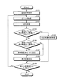
続いて、内視鏡システム1が行う画像取得処理について説明する。図3は、本発明の実施の形態1にかかる内視鏡システム1が行う画像取得処理を示すフローチャートである。以下、制御部36の制御のもと、各部が動作するものとして説明する。また、露光時間は、通常は、通常露光時間(1フレームに応じた露光時間)に設定されているものとして説明する。
Next, image acquisition processing performed by the endoscope system 1 will be described. FIG. 3 is a flowchart showing image acquisition processing performed by the endoscope system 1 according to the first embodiment of the present invention. Hereinafter, description will be made assuming that each unit operates under the control of the
撮像信号取得部31は、内視鏡2から撮像信号を取得すると、信号処理により赤色(R)、緑色(G)および青色(B)の色成分が付与された画像を含む入力画像信号を生成し、ビニング処理部32および測光部33に入力する(ステップS101)。
When the imaging
ビニング処理部32は、入力画像信号が入力されると、画素群に含まれる信号値(輝度値)を加算することにより、ビニング画素単位で信号値(輝度値)を生成することで、ビニング画像信号を生成する(ステップS102)。ビニング処理部32は、生成したビニング画像信号を表示画像生成部34に入力する。
When an input image signal is input, the
測光部33は、撮像信号取得部31から出力された入力画像信号における画像の明るさ、例えば信号レベルを測定する(ステップS103)。測光部33は、画像の明るさを含む測定結果を制御部36に入力する。
The
その後、明るさ制御部361が、入力された信号レベルと、明るさ調整情報記憶部371に記憶されている明るさの適正範囲における上限値とを比較し、信号レベルが上限値よりも大きいか否かを判断する(ステップS104)。この際の上限値は、ビニング処理後の画像の明るさを示す信号レベルが、画像処理により補正可能なレベルの上限を超えるか否かを判定する値として設定される。
Thereafter, the
明るさ制御部361は、信号レベルが上限値以下であると判断した場合(ステップS104:No)、ステップS106に移行する。これに対して、明るさ制御部361は、信号レベルが上限値より大きいと判断した場合(ステップS104:Yes)、ステップS105に移行する。
If the
ステップS105では、明るさ制御部361が、光源301aから出射される照明光の光量を低減する制御を行う。明るさ制御部361は、例えば、所定の割合、または所定量だけ光量を低減する。明るさ制御部361は、光源301aの光量を低減させた後、ステップS109に移行する。
In step S105, the
また、ステップS106では、明るさ制御部361が、入力された信号レベルと、明るさ調整情報記憶部371に記憶されている閾値とを比較し、信号レベルが明るさの適正範囲における下限値より小さいか否かを判断する(ステップS106)。この際の下限値は、ビニング処理後の画像の明るさを示す信号レベルが、明瞭な画像を生成できるレベルに達するか否かを判定する値として設定される。
In step S106, the
明るさ制御部361は、信号レベルが下限値以上であると判断した場合(ステップS106:No)、ステップS108に移行する。これに対して、明るさ制御部361は、信号レベルが下限値より小さいと判断した場合(ステップS106:Yes)、ステップS107に移行する。
If the
ステップS107では、明るさ制御部361が、次に撮像処理を行う際の露光モードを長時間露光モードに設定する。具体的に、明るさ制御部361は、通常の露光時間が1フレームの撮像信号を取得する時間に設定されているのに対し、長時間露光モードでは、この1フレームに応じた時間よりも長い時間で露光するような露光時間に設定する。例えば、1.5フレーム分の露光時間で1フレームの撮像信号を取得するような設定にしたり、2フレーム分の露光時間で1フレームの撮像信号を取得するような設定にしたりする。明るさ制御部361による露光モード設定後、ステップS108に移行する。なお、0.2フレーム分の露光時間を順次加算して累積した露光時間となるようにしてもよいし、測光値と基準値との比をもとに露光時間を決定するものであってもよい。この場合、露光時間が上限に達した場合は、上限を維持した露光時間を設定するとともに、表示装置4などによって露光時間が上限に達した旨を報知してもよい。
In step S107, the
ステップS108では、表示画像生成部34が、ビニング処理部32が生成したビニング画像信号に対して、表示装置4で表示可能な態様の信号となるような信号処理を施して、表示用の画像信号を生成する。表示画像生成部34は、生成した画像信号を表示装置4に出力する。表示装置4は、入力された画像信号に応じた画像を表示する。
In step S <b> 108, the display
表示画像生成部34による画像信号の生成後、制御部36は、新たな撮像信号の入力があるか否かを判断する(ステップS109)。制御部36は、例えば、新たな撮像信号の入力があると判断すると(ステップS109:Yes)、ステップS102に戻って上述した処理を繰り返し、新たな撮像信号の入力がないと判断すると(ステップS109:No)、画像取得処理を終了する。
After the image signal is generated by the display
上述した本実施の形態1によれば、ビニング処理部32が、入力された入力画像信号に対してビニング処理を行うとともに、明るさ制御部361が、測光部33の測定結果に応じて、次のフレームの撮像処理における露光時間を調整するようにしたので、ビニング処理により画像の明るさを向上するとともに、露光時間の調整によって信号値を大きくすることで、全体的な画像の明るさを向上した画像を取得することができる。
According to the first embodiment described above, the
なお、上述した本実施の形態1では、明るさ制御部361が、一つの閾値(下限値)を用いて露光時間を制御するものとして説明したが、複数の閾値であって、下限値や、下限値と上限値との間の一つまたは複数の値を含む複数の閾値と信号レベルとを比較して、当該信号レベルを含む閾値間の位置に応じて露光時間を設定するようにしてもよい。
In the first embodiment described above, the
また、上述した本実施の形態1において、ビニング処理(図3のステップS102)よりも先に測光処理(図3のステップS103)を行ってもよいし、同時に行ってもよい。 In the first embodiment described above, the photometric process (step S103 in FIG. 3) may be performed prior to the binning process (step S102 in FIG. 3) or may be performed simultaneously.
また、上述した本実施の形態1において、ビニング処理を撮像素子244で行って、撮像信号取得部31が、ビニング処理後の撮像信号を取得するものであってもよい。この場合、画素により生成される電荷レベルでビニング処理が行われる。
Further, in the first embodiment described above, the binning process may be performed by the
(実施の形態2)
次に、本発明の実施の形態2について、図4を参照して説明する。上述した実施の形態1はビニング処理を行って、測定結果により露光時間を調整するものとして説明したが、本実施の形態2では、長時間露光に設定した後、測定結果に基づいて、入力画像信号に対してビニング処理を行うか否かを判断する。なお、本発明の実施の形態2にかかる内視鏡システムの構成は、上述した内視鏡システム1の構成と同じである。図4は、本発明の実施の形態2にかかる内視鏡システム1が行う画像取得処理を示すフローチャートである。以下、制御部36の制御のもと、各部が動作するものとして説明する。
(Embodiment 2)
Next,
本実施の形態2では、明るさ制御部361が、まず、露光モードを長時間露光モードに設定する(ステップS201)。明るさ制御部361は、例えば、通常の1フレーム分の処理時間に応じた露光時間に対し、2フレーム分の処理時間に応じた時間を、1フレーム分の撮像信号を取得するための露光時間に設定する。
In the second embodiment, the
撮像信号取得部31は、内視鏡2から撮像信号を取得すると、信号処理により赤色(R)、緑色(G)および青色(B)の色成分が付与された画像を含む入力画像信号を生成し、ビニング処理部32および測光部33に入力する(ステップS202)。
When the imaging
測光部33は、撮像信号取得部31から出力された入力画像信号における画像の明るさ、例えば信号レベルを測定する(ステップS203)。測光部33は、画像の明るさを含む測定結果を制御部36に入力する。
The
その後、明るさ制御部361が、入力された信号レベルと、明るさ調整情報記憶部371に記憶されている明るさの適正範囲における上限値とを比較し、信号レベルが上限値よりも大きいか否かを判断する(ステップS204)。この際の上限値は、長時間露光モードにおいて撮像信号取得部31が取得した入力画像信号の画像の明るさを示す信号レベルが、画像処理により補正可能なレベルの上限を超えているか否かを判定する値として設定される。
Thereafter, the
明るさ制御部361は、信号レベルが上限値以下であると判断した場合(ステップS204:No)、ステップS206に移行する。これに対して、明るさ制御部361は、信号レベルが上限値より大きいと判断した場合(ステップS204:Yes)、ステップS205に移行する。
When the
ステップS205では、明るさ制御部361が、光源301aから出射される照明光の光量を低減する制御を行う。明るさ制御部361は、例えば、所定の割合、または所定量だけ光量を低減する。明るさ制御部361は、光源301aの光量を低減させた後、ステップS209に移行する。
In step S205, the
また、ステップS106では、明るさ制御部361が、入力された信号レベルと、明るさ調整情報記憶部371に記憶されている適正範囲の下限値とを比較し、信号レベルが下限値より小さいか否かを判断する(ステップS204)。この際の下限値は、長時間露光モードにおいて撮像信号取得部31が取得した入力画像信号の画像の明るさを示す信号レベルが、明瞭な画像のレベルに達しているか否かを判定する値として設定される。
In step S106, the
明るさ制御部361は、信号レベルが下限値以上であると判断した場合(ステップS206:No)、ステップS208に移行する。これに対して、明るさ制御部361は、信号レベルが閾値より小さいと判断した場合(ステップS206:Yes)、ステップS207に移行する。
If the
ステップS207では、ビニング処理部32は、入力された入力画像信号の画素群に含まれる信号値(輝度値)を加算することにより、ビニング画素単位で信号値(輝度値)を生成することで、ビニング画像信号を生成する。この際、ビニング処理部32は、明るさ制御部361が設定した画素群の数(画素群の形成パターン)に応じて、画素群からなるビニング画素の信号値を生成する。明るさ制御部361は、明るさ調整情報記憶部371に記憶されている情報に基づいて、ビニング処理の設定を行う。ビニング処理部32は、ビニング画像信号を生成後、ステップS208に移行する。
In step S207, the
ステップS208では、表示画像生成部34が、ビニング処理部32が生成したビニング画像信号に対して、表示装置4で表示可能な態様の信号となるような信号処理を施して、表示用の画像信号を生成する。表示画像生成部34は、生成した画像信号を表示装置4に出力する。表示装置4は、入力された画像信号に応じた画像を表示する。
In step S <b> 208, the display
表示画像生成部34による画像信号の生成後、制御部36は、新たな撮像信号の入力があるか否かを判断する(ステップS209)。制御部36は、例えば、新たな撮像信号の入力があると判断すると(ステップS209:Yes)、ステップS202に戻って上述した処理を繰り返し、新たな撮像信号の入力がないと判断すると(ステップS209:No)、画像取得処理を終了する。
After the image signal is generated by the display
上述した本実施の形態2によれば、明るさ制御部361が、長時間露光モードに設定するとともに、測光部33の測定結果に応じて、ビニング処理部32が、入力された入力画像信号に対してビニング処理を行うようにしたので、ビニング処理により画像の明るさを向上するとともに、露光時間の調整によって信号値を大きくすることで、全体的な画像の明るさを向上した画像を取得することができる。
According to the second embodiment described above, the
なお、上述した本実施の形態2では、明るさ制御部361が、一つの閾値(下限値)を用いてビニング処理における画素群の数(画素群の形成パターン)を設定するものとして説明したが、複数の閾値であって、下限値や、下限値と上限値との間の一つまたは複数の値を含む複数の閾値と信号レベルとを比較して、当該信号レベルを含む閾値間の位置に応じて画素群の数(画素群の形成パターン)を設定するようにしてもよい。
In the above-described second embodiment, the
(実施の形態3)
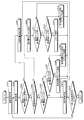
次に、本発明の実施の形態3について、図5を参照して説明する。上述した実施の形態1,2ではビニング処理または長時間露光制御のいずれかを行った後、測定結果により露光時間またはビニング処理の実施可否を判断するものとして説明したが、本実施の形態3では、明るさ制御部361が、制御部36の制御のもと画像の解像度およびフレームレートのいずれかを優先する制御を実行可能であり、かつ判断結果に応じて、長時間露光制御および/またはビニング処理の実施可否を判断する。なお、本発明の実施の形態3にかかる内視鏡システムの構成は、上述した内視鏡システム1の構成と同じである。図5は、本発明の実施の形態3にかかる内視鏡システム1が行う画像取得処理を示すフローチャートである。以下、制御部36の制御のもと、各部が動作するものとして説明する。なお、本実施の形態3では、明るさ調整情報記憶部371が、条件に応じた複数の閾値を記憶しているものとして説明する。
(Embodiment 3)
Next,
本実施の形態3では、まず、撮像信号取得部31が、内視鏡2から撮像信号を取得すると、信号処理により赤色(R)、緑色(G)および青色(B)の色成分が付与された画像を含む入力画像信号を生成し、ビニング処理部32および測光部33に入力する(ステップS301)。
In the third embodiment, first, when the imaging
測光部33は、撮像信号取得部31から出力された入力画像信号における画像の明るさ、例えば信号レベルを測定する(ステップS302)。測光部33は、画像の明るさを含む測定結果を制御部36に入力する。
The
その後、明るさ制御部361が、入力された信号レベルと、明るさ調整情報記憶部371に記憶されている明るさの適正範囲における上限値とを比較し、信号レベルが上限値よりも大きいか否かを判断する(ステップS303)。この際の上限値は、撮像信号取得部31が取得した入力画像信号の画像の明るさを示す信号レベルが、画像処理により補正可能なレベルの上限を超えているか否かを判定する値として設定される。
Thereafter, the
明るさ制御部361は、信号レベルが上限値以下であると判断した場合(ステップS303:No)、ステップS305に移行する。これに対して、明るさ制御部361は、信号レベルが上限値より大きいと判断した場合(ステップS303:Yes)、ステップS304に移行する。
When the
ステップS304では、明るさ制御部361が、光源301aから出射される照明光の光量を低減する制御を行う。明るさ制御部361は、例えば、所定の割合、または所定量だけ光量を低減する。明るさ制御部361は、光源301aの光量を低減させた後、ステップS316に移行する。
In step S304, the
また、ステップS305では、制御部36が、入力部35を介して解像度を優先する旨の指示信号が入力されたか否かを判断する(ステップS305)。制御部36は、解像度を優先する旨の指示信号が入力されたと判断した場合(ステップS305:Yes)、画像取得モードを、解像度を優先するモードとして、ステップS306に移行する。
In step S305, the
ステップS306では、明るさ制御部361が、入力された信号レベルと、明るさ調整情報記憶部371に記憶されている第1閾値とを比較し、信号レベルが第1閾値より小さいか否かを判断する。この際の第1閾値は、適正範囲の下限値と略等しい値であって、画像の明るさを示す信号レベルが、明瞭な画像のレベルに十分に達しているか否かを判定する値として設定される。
In step S306, the
明るさ制御部361は、信号レベルが第1閾値以上であると判断した場合(ステップS306:No)、ステップS315に移行する。これに対して、明るさ制御部361は、信号レベルが第1閾値より小さいと判断した場合(ステップS306:Yes)、ステップS307に移行する。
When the
ステップS307では、明るさ制御部361が、入力された信号レベルと、明るさ調整情報記憶部371に記憶されている第2閾値とを比較し、信号レベルが第2閾値より小さいか否かを判断する。この際の第2閾値は、第1閾値よりも小さく下限値よりも大きい値であって、撮像信号取得部31が取得した入力画像信号の画像の明るさを示す信号レベルが、明瞭な画像を生成可能なレベルに達しているが、次のフレームの撮像処理では露光時間を調整することが好ましいレベルであるか、今回のフレームの信号レベルが明瞭な画像を生成するレベルに達しておらず、取得した撮像信号に対してビニング処理を施すとともに、次のフレームの撮像処理では露光時間を調整する必要があるレベルかを判定する値として設定される。
In step S307, the
明るさ制御部361は、信号レベルが第2閾値以上であると判断した場合(ステップS307:No)、ステップS308に移行する。これに対して、明るさ制御部361は、信号レベルが第2閾値より小さいと判断した場合(ステップS307:Yes)、ステップS309に移行する。
When the
ステップS308では、明るさ制御部361が、次に撮像処理を行う際の露光モードを長時間露光モードに設定する。明るさ制御部361は、上述したように、通常の露光時間が1フレームの撮像信号を取得する時間に設定されているのに対し、長時間露光モードでは、この1フレームに応じた時間よりも長い時間で露光するような露光時間に設定する。明るさ制御部361による明るさ調整処理後、制御部36は、ステップS315に移行する。
In step S308, the
また、ステップS309では、明るさ制御部361が、次に撮像処理を行う際の露光モードを長時間露光モードに設定するとともに、ビニング処理部32に対し、今回入力された入力画像信号のビニング処理を行わせるように制御する。明るさ制御部361は、上述したように、通常の露光時間が1フレームの撮像信号を取得する時間に設定されているのに対し、長時間露光モードでは、この1フレームに応じた時間よりも長い時間で露光するような露光時間に設定する。この際、ステップS308の露光時間と同じ露光時間に設定してもよいし、露光時間よりも長い露光時間に設定してもよい。また、ビニング処理部32は、入力された入力画像信号の画素群に含まれる信号値(輝度値)を加算することにより、ビニング画素単位で信号値(輝度値)を生成することで、ビニング画像信号を生成する。この際、ビニング処理部32は、明るさ制御部361が設定した画素群の数(画素群の形成パターン)に応じて、画素群からなるビニング画素の信号値を生成する。ビニング処理部32は、ビニング画像信号を生成後、ステップS315に移行する。
In step S309, the
一方、制御部36は、解像度を優先する旨の指示信号が入力されていないと判断した場合(ステップS305:Yes)、画像取得モードを、フレームレートを優先するモードとして、ステップS310に移行する。なお、本実施の形態3では、解像度優先モードとする指示入力があるか否かを判断し、解像度優先の指示がなければフレームレートを優先するものとして説明するが、入力部35を介してユーザに解像度優先か、フレームレート優先かを選択させるようにしてもよい。
On the other hand, when the
ステップS310では、明るさ制御部361が、通常露光モードに設定する。明るさ制御部361は、上述したように、1フレームの撮像信号を取得する処理時間に応じた時間を通常の露光時間として設定する。その後、制御部36は、ステップS311に移行する。なお、予め通常露光モードに設定されている場合、明るさ制御部361は、露光もモードの設定を行わずにステップS311に移行する。
In step S310, the
ステップS311では、明るさ制御部361が、入力された信号レベルと、明るさ調整情報記憶部371に記憶されている第1閾値とを比較し、信号レベルが第1閾値より小さいか否かを判断する。
In step S311, the
明るさ制御部361は、信号レベルが第1閾値以上であると判断した場合(ステップS311:No)、ステップS313に移行する。これに対して、明るさ制御部361は、信号レベルが第1閾値より小さいと判断した場合(ステップS311:Yes)、ステップS312に移行する。
If the
ステップS312では、明るさ制御部361が、入力された信号レベルと、明るさ調整情報記憶部371に記憶されている第3閾値とを比較し、信号レベルが第3閾値より小さいか否かを判断する。この際の第3閾値は、第1閾値よりも小さく下限値よりも大きい値であって、ビニング処理部32によるビニング処理後の画像の明るさを示す信号レベルが、次のフレームの撮像処理において露光時間を調整することが好ましいレベルであるか否かを判定する値として設定される。
In step S312, the
明るさ制御部361は、信号レベルが第3閾値以上であると判断した場合(ステップS312:No)、ステップS313に移行する。これに対して、明るさ制御部361は、信号レベルが第2閾値より小さいと判断した場合(ステップS312:Yes)、ステップS314に移行する。
If the
ステップS313では、ビニング処理部32が、入力された入力画像信号の画素群に含まれる信号値(輝度値)を加算することにより、ビニング画素単位で信号値(輝度値)を生成することで、ビニング画像信号を生成する。この際、ビニング処理部32は、明るさ制御部361が設定した画素群の数(画素群の形成パターン)に応じて、画素群からなるビニング画素の信号値を生成する。ビニング処理部32は、ビニング画像信号を生成後、ステップS315に移行する。
In step S313, the
また、ステップS314では、明るさ制御部361が、次に撮像処理を行う際の露光モードを長時間露光モードに設定するとともに、ビニング処理部32に対し、今回入力された入力画像信号のビニング処理を行わせるように制御する。明るさ制御部361は、上述したように、通常の露光時間が1フレームの撮像信号を取得する時間に設定されているのに対し、長時間露光モードでは、この1フレームに応じた時間よりも長い時間で露光するような露光時間に設定する。また、ビニング処理部32は、入力された入力画像信号の画素群に含まれる信号値(輝度値)を加算することにより、ビニング画素単位で信号値(輝度値)を生成することで、ビニング画像信号を生成する。この際、ビニング処理部32は、明るさ制御部361が設定した画素群の数(画素群の形成パターン)に応じて、画素群からなるビニング画素の信号値を生成する。ビニング処理部32は、ビニング画像信号を生成後、ステップS315に移行する。
In step S314, the
ステップS315では、表示画像生成部34が、撮像信号取得部31が生成した入力画像信号、またはビニング処理部32が生成したビニング画像信号に対して、表示装置4で表示可能な態様の信号となるような信号処理を施して、表示用の画像信号を生成する。表示画像生成部34は、生成した画像信号を表示装置4に出力する。表示装置4は、入力された画像信号に応じた画像を表示する。
In step S315, the display
表示画像生成部34による画像信号の生成後、制御部36は、新たな撮像信号の入力があるか否かを判断する(ステップS316)。制御部36は、例えば、新たな撮像信号の入力があると判断すると(ステップS316:Yes)、ステップS302に戻って上述した処理を繰り返し、新たな撮像信号の入力がないと判断すると(ステップS316:No)、画像取得処理を終了する。
After the image signal is generated by the display
上述した本実施の形態3によれば、解像度優先およびフレームレート優先のいずれかを選択可能であり、それぞれの優先モードにおいて、信号レベルに応じてビニング処理および/または露光時間の調整を行うようにしたので、ビニング処理により画像の明るさを向上するとともに、露光時間の調整によって信号値を大きくすることで、全体的な画像の明るさを向上した画像を取得することができる。 According to the third embodiment described above, either resolution priority or frame rate priority can be selected, and in each priority mode, binning processing and / or exposure time adjustment is performed according to the signal level. Therefore, it is possible to obtain an image with improved overall image brightness by improving the brightness of the image by binning and increasing the signal value by adjusting the exposure time.
上述した本実施の形態3において、第2閾値よりも小さい第3閾値を設けて、測光値が第3閾値以下の場合に、明るさ制御部361が、優先モードに応じたビニング処理強度(ビニング処理において加算する画素数)および/または露光時間の調整を行うようにしても良い。具体的には、解像度優先モードである場合に測光値が第3の閾値以下である場合には、S307において設定されたビニング処理を行いつつ、S307において設定される長時間露光モードよりも長い時間で露光を行い、フレームレート優先モードである場合に測光値が第3の閾値以下である場合には、S312において設定された長時間露光モードに設定しつつ、S312において設定されるビニング処理よりも画素加算数を増やすようにビニング処理を設定しても良い。
In the third embodiment described above, when the third threshold value smaller than the second threshold value is provided and the photometric value is equal to or smaller than the third threshold value, the
なお、上述した実施の形態1〜3では、撮像信号取得部31が、RGBの各色成分が付与された画像を含む入力画像信号を生成するものとして説明したが、YCbCr色空間に基づいて輝度(Y)成分および色差成分を含むYCbCr色空間を有する入力画像信号を生成するものであってもよいし、色相(Hue)、彩度(Saturation Chroma)、明度(Value Lightness Brightness)の三つの成分からなるHSV色空間や、三次元空間を用いるL*a*b*色空間などを用いて、色と輝度とに分けた成分を有する入力画像信号を生成するものであってもよい。
In Embodiments 1 to 3 described above, the imaging
また、上述した実施の形態1〜3において、明るさ制御部361が、入力部35が受け付けた操作入力に応じてビニングの画素群数や、長時間露光モードにおける露光時間を設定するようにしてもよい。
In the first to third embodiments, the
また、上述した実施の形態1〜3では、光源部3aから白色光が出射され、受光部244aがRGBの各色成分の光を受光する同時式の照明/撮像方式であるものとして説明したが、光源部3aが、RGBの色成分の波長帯域の光を個別に順次出射して、受光部244aが、各色成分の光をそれぞれ受光する面順次式の照明/撮像方式であってもよい。
In the above-described first to third embodiments, white light is emitted from the
また、上述した実施の形態1〜3では、光源部3aが内視鏡2とは別体で構成されているものとして説明したが、例えば、内視鏡2の先端に半導体光源を設けるなど、光源装置を内視鏡2に設けた構成であってもよい。さらに、内視鏡2に処理装置3の機能を付与してもよい。
In the first to third embodiments described above, the
また、上述した実施の形態1〜3では、光源部3aが、処理装置3とは一体であるものとして説明したが、光源部3aおよび処理装置3が別体であって、例えば処理装置3の外部に照明部301および照明制御部302が設けられているものであってもよい。また、光源301aが先端部24の先端に設けられているものであってもよい。
In the first to third embodiments described above, the
また、上述した実施の形態1〜3では、本発明にかかる撮像システムが、観察対象が被検体内の生体組織などである軟性の内視鏡2を用いた内視鏡システム1の撮像素子244、ビニング処理部32、測光部33および明るさ制御部361として機能するものとして説明したが、硬性の内視鏡や、材料の特性を観測する工業用の内視鏡、カプセル型の内視鏡、ファイバースコープ、光学視管などの光学内視鏡の接眼部にカメラヘッドを接続したものを用いた内視鏡システムであっても適用できる。本発明にかかる撮像システムは、体内、体外を問わず適用可能であり、外部で生成された撮像信号などの画像信号であって、画素の配置情報などの位置情報をそれぞれ有する複数の信号値を含む画像信号に対して所定数ごとに信号値を加算した加算信号値を生成するビニング処理を行うとともに、画像信号の取得にかかる露光時間について長時間露光制御を行うことが可能な処理装置を含むものである。
In Embodiments 1 to 3 described above, the imaging system according to the present invention uses the
また、上述した実施の形態1〜3では、内視鏡システムを例に挙げて説明したが、例えばデジタルスチルカメラ等に設けられるEVF(Electronic View Finder)に映像を出力する場合にも適用可能である。 In the first to third embodiments described above, the endoscope system has been described as an example. However, the present invention can also be applied to, for example, outputting an image to an EVF (Electronic View Finder) provided in a digital still camera or the like. is there.
以上のように、本発明にかかる撮像システムおよび処理装置は、全体的な画像の明るさを向上した画像を取得するのに有用である。 As described above, the imaging system and the processing apparatus according to the present invention are useful for acquiring an image with improved overall image brightness.
1 内視鏡システム
2 内視鏡
3 処理装置
3a 光源部
4 表示装置
21 挿入部
22 操作部
23 ユニバーサルコード
24 先端部
25 湾曲部
26 可撓管部
31 撮像信号取得部
32 ビニング処理部
33 測光部
34 表示画像生成部
35 入力部
36 制御部
37 記憶部
301 照明部
302 照明制御部
361 明るさ制御部
371 明るさ調整情報記憶部
DESCRIPTION OF SYMBOLS 1
Claims (7)
前記撮像信号が含む複数の電気信号に基づいて、当該撮像信号に基づく画像の明るさを示す測光値を生成する測光部と、
前記複数の画素を所定数の画素ごとに分割した複数の画素群における複数の電気信号を加算することによって前記画素群ごとの信号値を生成するビニング処理部と、
前記測光部の測光結果が、前記撮像信号に基づく画像の明るさが所定の明るさよりも暗い場合に、前記撮像部が行う撮像処理における露光時間を長くする長時間露光制御、および前記ビニング処理部による前記撮像信号のビニング処理の少なくともいずれか一方を選択する明るさ制御部と、
を備えたことを特徴とする撮像システム。 An imaging unit that generates a plurality of pixels that generate an electrical signal by photoelectrically converting light received from a subject, and that generates an imaging signal that includes the plurality of electrical signals generated by each of the plurality of pixels;
Based on a plurality of electrical signals included in the imaging signal, a photometry unit that generates a photometric value indicating the brightness of an image based on the imaging signal;
A binning processing unit that generates a signal value for each pixel group by adding a plurality of electrical signals in a plurality of pixel groups obtained by dividing the plurality of pixels for each predetermined number of pixels;
Long-time exposure control for increasing the exposure time in the imaging process performed by the imaging unit when the brightness of an image based on the imaging signal is darker than a predetermined brightness, and the binning processing unit A brightness control unit that selects at least one of the binning processing of the image pickup signal by:
An imaging system comprising:
ことを特徴とする請求項1に記載の撮像システム。 The imaging according to claim 1, wherein the brightness control unit selects at least one of the long-time exposure control and the binning process based on a comparison result obtained by comparing the photometric value and a threshold value. system.
ことを特徴とする請求項1に記載の撮像システム。 The brightness control unit causes the binning processing to be performed by the binning processing unit, and the photometry unit has a photometry result when the brightness of an image based on the imaging signal is darker than a predetermined brightness. The imaging system according to claim 1, wherein long-time exposure control is performed to increase an exposure time in an imaging process performed by.
ことを特徴とする請求項1に記載の撮像システム。 The brightness control unit performs long-time exposure control to increase an exposure time in an imaging process performed by the imaging unit, and the photometry result of the photometry unit indicates that the brightness of an image based on the imaging signal is higher than a predetermined brightness. The imaging system according to claim 1, wherein the binning processing unit is configured to perform the binning processing when the image is dark.
前記画像の解像度およびフレームレートのいずれかを優先する制御を実行可能であり、
前記画像の解像度を優先する制御を行う場合、前記測光値が第1閾値よりも小さく、かつ第2閾値よりも大きければ、前記撮像部が行う撮像処理における露光時間を長くする長時間露光制御を行い、前記測光値が前記第2閾値よりも小さければ、前記撮像部が行う撮像処理における露光時間を長くする長時間露光制御を行うとともに、前記ビニング処理部に前記ビニング処理を行わせる制御を行い、
前記画像のフレームレートを優先する制御を行う場合、前記測光値が第1閾値よりも小さく、かつ第3閾値よりも大きければ、前記ビニング処理部による前記ビニング処理を行わせる制御を行い、前記測光値が前記第3閾値よりも小さければ、前記ビニング処理部に前記ビニング処理を行わせる制御を行うとともに、前記撮像部が行う撮像処理における露光時間を長くする長時間露光制御を行う
ことを特徴とする請求項1に記載の撮像システム。 The brightness control unit
Control that prioritizes either the resolution or the frame rate of the image can be executed,
When performing control giving priority to the resolution of the image, long exposure control is performed to increase the exposure time in the imaging process performed by the imaging unit if the photometric value is smaller than the first threshold and greater than the second threshold. If the photometric value is smaller than the second threshold value, long exposure control is performed to increase the exposure time in the imaging processing performed by the imaging unit, and control is performed to cause the binning processing unit to perform the binning process. ,
When performing control to give priority to the frame rate of the image, if the photometric value is smaller than a first threshold value and larger than a third threshold value, control to perform the binning process by the binning processing unit is performed, and the photometry is performed. If the value is smaller than the third threshold value, the binning processing unit is controlled to perform the binning process, and long-time exposure control is performed to increase the exposure time in the imaging process performed by the imaging unit. The imaging system according to claim 1.
ことを特徴とする請求項1〜5のいずれか一つに記載の撮像システム。 The said brightness control part performs the said long time exposure control by increasing the normal exposure time required when acquiring the said some electric signal which comprises the image based on the said imaging signal. The imaging system according to any one of 1 to 5.
前記複数の電気信号に基づいて、当該画像信号に基づく画像の明るさを示す測光値を生成する測光部と、
前記位置情報に基づいて、所定数の電気信号ごとに加算処理を行って、該所定数の電気信号の加算信号値をそれぞれ生成するビニング処理部と、
前記測光部の測光結果が、前記画像信号に基づく画像の明るさが所定の明るさよりも暗い場合に、前記画像信号を取得する際の露光時間を長くする長時間露光制御、および前記ビニング処理部による前記画像信号のビニング処理の少なくともいずれか一方を選択する明るさ制御部と、
を備えたことを特徴とする処理装置。 A processing device that performs signal processing on an image signal including a plurality of electrical signals each having position information,
A photometric unit that generates a photometric value indicating the brightness of the image based on the image signal based on the plurality of electrical signals;
A binning processing unit that performs addition processing for each predetermined number of electrical signals based on the position information, and generates an addition signal value for each of the predetermined number of electrical signals;
Long-time exposure control for increasing the exposure time when acquiring the image signal when the brightness of the image based on the image signal is darker than a predetermined brightness, and the binning processing unit. A brightness control unit for selecting at least one of the binning processing of the image signal by:
A processing apparatus comprising:
Priority Applications (1)
| Application Number | Priority Date | Filing Date | Title |
|---|---|---|---|
| JP2016004575A JP2017123997A (en) | 2016-01-13 | 2016-01-13 | Imaging system and processing device |
Applications Claiming Priority (1)
| Application Number | Priority Date | Filing Date | Title |
|---|---|---|---|
| JP2016004575A JP2017123997A (en) | 2016-01-13 | 2016-01-13 | Imaging system and processing device |
Publications (1)
| Publication Number | Publication Date |
|---|---|
| JP2017123997A true JP2017123997A (en) | 2017-07-20 |
Family
ID=59363537
Family Applications (1)
| Application Number | Title | Priority Date | Filing Date |
|---|---|---|---|
| JP2016004575A Pending JP2017123997A (en) | 2016-01-13 | 2016-01-13 | Imaging system and processing device |
Country Status (1)
| Country | Link |
|---|---|
| JP (1) | JP2017123997A (en) |
Cited By (3)
| Publication number | Priority date | Publication date | Assignee | Title |
|---|---|---|---|---|
| CN108650473A (en) * | 2018-05-28 | 2018-10-12 | 重庆金山医疗器械有限公司 | The method and system of endoscope LED light automatic brightness adjustment |
| JP2021527980A (en) * | 2018-06-18 | 2021-10-14 | シーイング マシーンズ リミテッド | High frame rate image preprocessing system and method |
| CN116325776A (en) * | 2020-09-29 | 2023-06-23 | 富士胶片株式会社 | Imaging device, driving method and program of imaging device |
Citations (5)
| Publication number | Priority date | Publication date | Assignee | Title |
|---|---|---|---|---|
| JP2001285684A (en) * | 2000-03-30 | 2001-10-12 | Minolta Co Ltd | Electronic camera |
| JP2005020565A (en) * | 2003-06-27 | 2005-01-20 | Toshiba Corp | Imaging apparatus and information processing method of imaging apparatus |
| JP2005094346A (en) * | 2003-09-17 | 2005-04-07 | Matsushita Electric Ind Co Ltd | Surveillance video camera |
| WO2013039061A1 (en) * | 2011-09-13 | 2013-03-21 | Necカシオモバイルコミュニケーションズ株式会社 | Imaging device, imaging method and recording medium |
| JP2014014438A (en) * | 2012-07-06 | 2014-01-30 | Fujifilm Corp | Endoscope system, processor device for endoscope system, and endoscope control program |
-
2016
- 2016-01-13 JP JP2016004575A patent/JP2017123997A/en active Pending
Patent Citations (5)
| Publication number | Priority date | Publication date | Assignee | Title |
|---|---|---|---|---|
| JP2001285684A (en) * | 2000-03-30 | 2001-10-12 | Minolta Co Ltd | Electronic camera |
| JP2005020565A (en) * | 2003-06-27 | 2005-01-20 | Toshiba Corp | Imaging apparatus and information processing method of imaging apparatus |
| JP2005094346A (en) * | 2003-09-17 | 2005-04-07 | Matsushita Electric Ind Co Ltd | Surveillance video camera |
| WO2013039061A1 (en) * | 2011-09-13 | 2013-03-21 | Necカシオモバイルコミュニケーションズ株式会社 | Imaging device, imaging method and recording medium |
| JP2014014438A (en) * | 2012-07-06 | 2014-01-30 | Fujifilm Corp | Endoscope system, processor device for endoscope system, and endoscope control program |
Cited By (5)
| Publication number | Priority date | Publication date | Assignee | Title |
|---|---|---|---|---|
| CN108650473A (en) * | 2018-05-28 | 2018-10-12 | 重庆金山医疗器械有限公司 | The method and system of endoscope LED light automatic brightness adjustment |
| CN108650473B (en) * | 2018-05-28 | 2020-07-28 | 重庆金山医疗器械有限公司 | Method and system for automatically adjusting brightness of endoscope L ED lamp |
| JP2021527980A (en) * | 2018-06-18 | 2021-10-14 | シーイング マシーンズ リミテッド | High frame rate image preprocessing system and method |
| US12198312B2 (en) | 2018-06-18 | 2025-01-14 | Seeing Machines Limited | High frame rate image pre-processing system and method |
| CN116325776A (en) * | 2020-09-29 | 2023-06-23 | 富士胶片株式会社 | Imaging device, driving method and program of imaging device |
Similar Documents
| Publication | Publication Date | Title |
|---|---|---|
| JP5968944B2 (en) | Endoscope system, processor device, light source device, operation method of endoscope system, operation method of processor device, operation method of light source device | |
| JP5245022B1 (en) | Imaging device | |
| US12426771B2 (en) | Endoscope system, image processing device, total processing time detection method, and processing device | |
| WO2012033200A1 (en) | Image capture device | |
| JPWO2017002544A1 (en) | Image processing apparatus and imaging system | |
| JP6346501B2 (en) | Endoscope device | |
| US10574934B2 (en) | Ultrasound observation device, operation method of image signal processing apparatus, image signal processing method, and computer-readable recording medium | |
| JPWO2016084257A1 (en) | Endoscope device | |
| WO2016104386A1 (en) | Dimmer, imaging system, method for operating dimmer, and operating program for dimmer | |
| JPWO2017022324A1 (en) | Endoscopy system signal processing method and endoscope system | |
| WO2016088628A1 (en) | Image evaluation device, endoscope system, method for operating image evaluation device, and program for operating image evaluation device | |
| JP6937902B2 (en) | Endoscope system | |
| US10462440B2 (en) | Image processing apparatus | |
| JP2017123997A (en) | Imaging system and processing device | |
| JP6503522B1 (en) | Image processing apparatus, image processing system and image processing method | |
| WO2020003601A1 (en) | Endoscope light source device | |
| WO2019130834A1 (en) | Image processing device and image processing method | |
| JP6801990B2 (en) | Image processing system and image processing equipment | |
| JP2018007840A (en) | Image processing device | |
| JP2018151679A (en) | Image signal processing method, image signal processing apparatus and image signal processing program | |
| JP2017221276A (en) | Image processing device | |
| WO2018079387A1 (en) | Image processing device and image processing system |
Legal Events
| Date | Code | Title | Description |
|---|---|---|---|
| A621 | Written request for application examination |
Free format text: JAPANESE INTERMEDIATE CODE: A621 Effective date: 20181226 |
|
| A131 | Notification of reasons for refusal |
Free format text: JAPANESE INTERMEDIATE CODE: A131 Effective date: 20191105 |
|
| A977 | Report on retrieval |
Free format text: JAPANESE INTERMEDIATE CODE: A971007 Effective date: 20191031 |
|
| A02 | Decision of refusal |
Free format text: JAPANESE INTERMEDIATE CODE: A02 Effective date: 20200616 |