JP2017125594A - Disc brake rotor for bicycle - Google Patents
Disc brake rotor for bicycle Download PDFInfo
- Publication number
- JP2017125594A JP2017125594A JP2016006311A JP2016006311A JP2017125594A JP 2017125594 A JP2017125594 A JP 2017125594A JP 2016006311 A JP2016006311 A JP 2016006311A JP 2016006311 A JP2016006311 A JP 2016006311A JP 2017125594 A JP2017125594 A JP 2017125594A
- Authority
- JP
- Japan
- Prior art keywords
- peripheral portion
- inner peripheral
- disc brake
- brake rotor
- outer peripheral
- Prior art date
- Legal status (The legal status is an assumption and is not a legal conclusion. Google has not performed a legal analysis and makes no representation as to the accuracy of the status listed.)
- Pending
Links
- 230000002093 peripheral effect Effects 0.000 claims abstract description 264
- 238000001816 cooling Methods 0.000 claims abstract description 39
- 230000005855 radiation Effects 0.000 claims abstract description 11
- 239000000463 material Substances 0.000 claims description 26
- 230000001737 promoting effect Effects 0.000 claims description 11
- XAGFODPZIPBFFR-UHFFFAOYSA-N aluminium Chemical compound [Al] XAGFODPZIPBFFR-UHFFFAOYSA-N 0.000 claims description 6
- 229910052782 aluminium Inorganic materials 0.000 claims description 6
- 239000010935 stainless steel Substances 0.000 claims description 6
- 229910001220 stainless steel Inorganic materials 0.000 claims description 6
- 229910000838 Al alloy Inorganic materials 0.000 claims description 5
- 238000005452 bending Methods 0.000 claims description 4
- 230000008878 coupling Effects 0.000 claims 2
- 238000010168 coupling process Methods 0.000 claims 2
- 238000005859 coupling reaction Methods 0.000 claims 2
- 230000001133 acceleration Effects 0.000 abstract 1
- 230000017525 heat dissipation Effects 0.000 description 14
- 238000000034 method Methods 0.000 description 4
- 230000004048 modification Effects 0.000 description 4
- 238000012986 modification Methods 0.000 description 4
- 230000000149 penetrating effect Effects 0.000 description 3
- 238000013459 approach Methods 0.000 description 2
- 230000015572 biosynthetic process Effects 0.000 description 2
- 230000000694 effects Effects 0.000 description 2
- 238000005530 etching Methods 0.000 description 2
- 238000005299 abrasion Methods 0.000 description 1
- 239000000853 adhesive Substances 0.000 description 1
- 230000001070 adhesive effect Effects 0.000 description 1
- 239000011248 coating agent Substances 0.000 description 1
- 238000000576 coating method Methods 0.000 description 1
- 230000008094 contradictory effect Effects 0.000 description 1
- 238000009792 diffusion process Methods 0.000 description 1
- 238000004519 manufacturing process Methods 0.000 description 1
- 230000000873 masking effect Effects 0.000 description 1
- 238000003825 pressing Methods 0.000 description 1
- XLYOFNOQVPJJNP-UHFFFAOYSA-N water Substances O XLYOFNOQVPJJNP-UHFFFAOYSA-N 0.000 description 1
Images




Classifications
-
- B—PERFORMING OPERATIONS; TRANSPORTING
- B62—LAND VEHICLES FOR TRAVELLING OTHERWISE THAN ON RAILS
- B62L—BRAKES SPECIALLY ADAPTED FOR CYCLES
- B62L1/00—Brakes; Arrangements thereof
-
- F—MECHANICAL ENGINEERING; LIGHTING; HEATING; WEAPONS; BLASTING
- F16—ENGINEERING ELEMENTS AND UNITS; GENERAL MEASURES FOR PRODUCING AND MAINTAINING EFFECTIVE FUNCTIONING OF MACHINES OR INSTALLATIONS; THERMAL INSULATION IN GENERAL
- F16D—COUPLINGS FOR TRANSMITTING ROTATION; CLUTCHES; BRAKES
- F16D65/00—Parts or details
- F16D65/02—Braking members; Mounting thereof
- F16D65/12—Discs; Drums for disc brakes
- F16D65/128—Discs; Drums for disc brakes characterised by means for cooling
-
- F—MECHANICAL ENGINEERING; LIGHTING; HEATING; WEAPONS; BLASTING
- F16—ENGINEERING ELEMENTS AND UNITS; GENERAL MEASURES FOR PRODUCING AND MAINTAINING EFFECTIVE FUNCTIONING OF MACHINES OR INSTALLATIONS; THERMAL INSULATION IN GENERAL
- F16D—COUPLINGS FOR TRANSMITTING ROTATION; CLUTCHES; BRAKES
- F16D65/00—Parts or details
- F16D65/02—Braking members; Mounting thereof
- F16D65/12—Discs; Drums for disc brakes
-
- F—MECHANICAL ENGINEERING; LIGHTING; HEATING; WEAPONS; BLASTING
- F16—ENGINEERING ELEMENTS AND UNITS; GENERAL MEASURES FOR PRODUCING AND MAINTAINING EFFECTIVE FUNCTIONING OF MACHINES OR INSTALLATIONS; THERMAL INSULATION IN GENERAL
- F16D—COUPLINGS FOR TRANSMITTING ROTATION; CLUTCHES; BRAKES
- F16D65/00—Parts or details
- F16D65/02—Braking members; Mounting thereof
- F16D65/12—Discs; Drums for disc brakes
- F16D65/123—Discs; Drums for disc brakes comprising an annular disc secured to a hub member; Discs characterised by means for mounting
-
- F—MECHANICAL ENGINEERING; LIGHTING; HEATING; WEAPONS; BLASTING
- F16—ENGINEERING ELEMENTS AND UNITS; GENERAL MEASURES FOR PRODUCING AND MAINTAINING EFFECTIVE FUNCTIONING OF MACHINES OR INSTALLATIONS; THERMAL INSULATION IN GENERAL
- F16D—COUPLINGS FOR TRANSMITTING ROTATION; CLUTCHES; BRAKES
- F16D65/00—Parts or details
- F16D65/02—Braking members; Mounting thereof
- F16D65/12—Discs; Drums for disc brakes
- F16D65/125—Discs; Drums for disc brakes characterised by the material used for the disc body
-
- F—MECHANICAL ENGINEERING; LIGHTING; HEATING; WEAPONS; BLASTING
- F16—ENGINEERING ELEMENTS AND UNITS; GENERAL MEASURES FOR PRODUCING AND MAINTAINING EFFECTIVE FUNCTIONING OF MACHINES OR INSTALLATIONS; THERMAL INSULATION IN GENERAL
- F16D—COUPLINGS FOR TRANSMITTING ROTATION; CLUTCHES; BRAKES
- F16D65/00—Parts or details
- F16D65/78—Features relating to cooling
- F16D65/84—Features relating to cooling for disc brakes
-
- F—MECHANICAL ENGINEERING; LIGHTING; HEATING; WEAPONS; BLASTING
- F16—ENGINEERING ELEMENTS AND UNITS; GENERAL MEASURES FOR PRODUCING AND MAINTAINING EFFECTIVE FUNCTIONING OF MACHINES OR INSTALLATIONS; THERMAL INSULATION IN GENERAL
- F16D—COUPLINGS FOR TRANSMITTING ROTATION; CLUTCHES; BRAKES
- F16D65/00—Parts or details
- F16D65/78—Features relating to cooling
- F16D65/84—Features relating to cooling for disc brakes
- F16D65/847—Features relating to cooling for disc brakes with open cooling system, e.g. cooled by air
-
- F—MECHANICAL ENGINEERING; LIGHTING; HEATING; WEAPONS; BLASTING
- F16—ENGINEERING ELEMENTS AND UNITS; GENERAL MEASURES FOR PRODUCING AND MAINTAINING EFFECTIVE FUNCTIONING OF MACHINES OR INSTALLATIONS; THERMAL INSULATION IN GENERAL
- F16D—COUPLINGS FOR TRANSMITTING ROTATION; CLUTCHES; BRAKES
- F16D65/00—Parts or details
- F16D65/02—Braking members; Mounting thereof
- F16D2065/13—Parts or details of discs or drums
- F16D2065/1304—Structure
- F16D2065/1316—Structure radially segmented
-
- F—MECHANICAL ENGINEERING; LIGHTING; HEATING; WEAPONS; BLASTING
- F16—ENGINEERING ELEMENTS AND UNITS; GENERAL MEASURES FOR PRODUCING AND MAINTAINING EFFECTIVE FUNCTIONING OF MACHINES OR INSTALLATIONS; THERMAL INSULATION IN GENERAL
- F16D—COUPLINGS FOR TRANSMITTING ROTATION; CLUTCHES; BRAKES
- F16D65/00—Parts or details
- F16D65/02—Braking members; Mounting thereof
- F16D2065/13—Parts or details of discs or drums
- F16D2065/1304—Structure
- F16D2065/132—Structure layered
-
- F—MECHANICAL ENGINEERING; LIGHTING; HEATING; WEAPONS; BLASTING
- F16—ENGINEERING ELEMENTS AND UNITS; GENERAL MEASURES FOR PRODUCING AND MAINTAINING EFFECTIVE FUNCTIONING OF MACHINES OR INSTALLATIONS; THERMAL INSULATION IN GENERAL
- F16D—COUPLINGS FOR TRANSMITTING ROTATION; CLUTCHES; BRAKES
- F16D65/00—Parts or details
- F16D65/02—Braking members; Mounting thereof
- F16D2065/13—Parts or details of discs or drums
- F16D2065/134—Connection
- F16D2065/1392—Connection elements
-
- F—MECHANICAL ENGINEERING; LIGHTING; HEATING; WEAPONS; BLASTING
- F16—ENGINEERING ELEMENTS AND UNITS; GENERAL MEASURES FOR PRODUCING AND MAINTAINING EFFECTIVE FUNCTIONING OF MACHINES OR INSTALLATIONS; THERMAL INSULATION IN GENERAL
- F16D—COUPLINGS FOR TRANSMITTING ROTATION; CLUTCHES; BRAKES
- F16D65/00—Parts or details
- F16D65/78—Features relating to cooling
- F16D2065/789—External cooling ribs
-
- F—MECHANICAL ENGINEERING; LIGHTING; HEATING; WEAPONS; BLASTING
- F16—ENGINEERING ELEMENTS AND UNITS; GENERAL MEASURES FOR PRODUCING AND MAINTAINING EFFECTIVE FUNCTIONING OF MACHINES OR INSTALLATIONS; THERMAL INSULATION IN GENERAL
- F16D—COUPLINGS FOR TRANSMITTING ROTATION; CLUTCHES; BRAKES
- F16D2250/00—Manufacturing; Assembly
- F16D2250/0084—Assembly or disassembly
Landscapes
- Engineering & Computer Science (AREA)
- General Engineering & Computer Science (AREA)
- Mechanical Engineering (AREA)
- Braking Arrangements (AREA)
Abstract
Description
本発明は、自転車用ディスクブレーキローターに関する。 The present invention relates to a bicycle disc brake rotor.
ディスクブレーキ装置を搭載した自転車が知られている。ディスクブレーキ装置は、ホイールと一体に回転するディスクブレーキローター、および、ディスクブレーキローターにブレーキパッドを押し付けることによりホイールに制動力を与えるキャリパーを含む。ブレーキパッドがディスクブレーキローターに押し付けられた場合、摩擦熱によりディスクブレーキローターの温度が上昇するため、ディスクブレーキローターには高い放熱性が求められる。例えば、特許文献1はディスクブレーキローターに複数のフィンを設けることにより、ディスクブレーキローターの放熱性を高める技術を開示している。 Bicycles equipped with disc brake devices are known. The disc brake device includes a disc brake rotor that rotates integrally with the wheel, and a caliper that applies a braking force to the wheel by pressing a brake pad against the disc brake rotor. When the brake pad is pressed against the disc brake rotor, the temperature of the disc brake rotor rises due to frictional heat, so that the disc brake rotor is required to have high heat dissipation. For example, Patent Document 1 discloses a technique for improving the heat dissipation of a disc brake rotor by providing a plurality of fins on the disc brake rotor.
本発明の目的は、放熱性をさらに高めた自転車用ディスクブレーキローターを提供することである。 An object of the present invention is to provide a bicycle disc brake rotor with further improved heat dissipation.
〔1〕本発明に従う自転車用ディスクブレーキローターの一形態は、回転中心軸心を含む自転車用ディスクブレーキローターであって、少なくとも1つのブレーキ面を含む少なくとも1つの外周部と、前記少なくとも1つの外周部と結合し、前記外周部に対して前記回転中心軸心に関する径方向内側に少なくとも一部が配置される第1の内周部および第2の内周部と、を備え、前記第1の内周部および前記第2の内周部は、前記回転中心軸心と平行な軸方向に関して前記第1の内周部と前記第2の内周部との間に空間が形成されるように配置され、前記第1の内周部および前記第2の内周部の少なくとも一方は、前記空間と連通する少なくとも1つの開口を含む少なくとも1つの冷却促進部を含む。 [1] An embodiment of a bicycle disc brake rotor according to the present invention is a bicycle disc brake rotor including a rotation center axis, wherein the at least one outer periphery includes at least one brake surface, and the at least one outer periphery. A first inner peripheral portion and a second inner peripheral portion that are at least partially disposed on the radially inner side with respect to the rotation center axis with respect to the outer peripheral portion. The inner circumferential portion and the second inner circumferential portion are formed so that a space is formed between the first inner circumferential portion and the second inner circumferential portion with respect to an axial direction parallel to the rotation center axis. And at least one of the first inner peripheral portion and the second inner peripheral portion includes at least one cooling promoting portion including at least one opening communicating with the space.
〔2〕前記自転車用ディスクブレーキローターの一例によれば、前記第1の内周部および前記第2の内周部は、前記回転中心軸心と平行な軸方向に関して対向するように配置されている。 [2] According to an example of the bicycle disc brake rotor, the first inner peripheral portion and the second inner peripheral portion are arranged to face each other in an axial direction parallel to the rotation center axis. Yes.
〔3〕前記自転車用ディスクブレーキローターの一例によれば、前記第1の内周部および前記第2の内周部は、前記回転中心軸心と平行な軸方向から見て前記外周部と部分的にオーバーラップする。 [3] According to one example of the disc brake rotor for bicycle, the first inner peripheral portion and the second inner peripheral portion are formed of the outer peripheral portion and the portion as viewed from an axial direction parallel to the rotation center axis. Overlap.
〔4〕前記自転車用ディスクブレーキローターの一例によれば、前記少なくとも1つの冷却促進部は、少なくとも1つの放熱フィンをさらに含む。
〔5〕前記自転車用ディスクブレーキローターの一例によれば、前記少なくとも1つの放熱フィンは、前記軸方向を向く少なくとも1つの放熱片を含む。
[4] According to one example of the bicycle disc brake rotor, the at least one cooling promoting portion further includes at least one heat radiation fin.
[5] According to one example of the bicycle disc brake rotor, the at least one radiating fin includes at least one radiating piece facing in the axial direction.
〔6〕前記自転車用ディスクブレーキローターの一例によれば、前記少なくとも1つの開口および前記少なくとも1つの放熱片は、前記第1の内周部および前記第2の内周部の少なくとも一方が部分的に曲げ加工されたことにより形成された部分である。 [6] According to an example of the bicycle disc brake rotor, at least one of the first inner peripheral portion and the second inner peripheral portion of the at least one opening and the at least one heat radiating piece is partially This is a portion formed by bending.
〔7〕前記自転車用ディスクブレーキローターの一例によれば、自転車のハブに取り付けられるハブ取付部を含む取付部材をさらに備える。
〔8〕前記自転車用ディスクブレーキローターの一例によれば、前記取付部材は、前記少なくとも1つの外周部と結合する。
[7] According to one example of the bicycle disc brake rotor, the bicycle further includes an attachment member including a hub attachment portion attached to the bicycle hub.
[8] According to an example of the bicycle disc brake rotor, the attachment member is coupled to the at least one outer peripheral portion.
〔9〕前記自転車用ディスクブレーキローターの一例によれば、前記少なくとも1つの放熱フィンは、前記回転中心軸心に関する径方向において、前記ハブ取付部と前記少なくとも1つの外周部との間に設けられる。 [9] According to an example of the bicycle disc brake rotor, the at least one radiating fin is provided between the hub mounting portion and the at least one outer peripheral portion in a radial direction with respect to the rotation center axis. .
〔10〕前記自転車用ディスクブレーキローターの一例によれば、前記取付部材は前記少なくとも1つの外周部と結合し、かつ、前記ハブ取付部から前記径方向外側に放射状に延びる少なくとも2つの連結部をさらに含み、前記少なくとも1つの放熱フィンは、前記回転中心軸心に関する周方向において、前記少なくとも2つの連結部の間に設けられる。 [10] According to an example of the bicycle disc brake rotor, the attachment member is coupled to the at least one outer peripheral portion, and includes at least two connection portions extending radially outward from the hub attachment portion. Further, the at least one radiating fin is provided between the at least two connecting portions in a circumferential direction with respect to the rotation center axis.
〔11〕前記自転車用ディスクブレーキローターの一例によれば、前記取付部材は、前記少なくとも1つの外周部と結合し、かつ、前記ハブ取付部から前記径方向外側に放射状に延びる少なくとも2つの連結部をさらに含み、前記第1の内周部および前記第2の内周部は、前記回転中心軸心と平行な軸方向から見て前記少なくとも2つの連結部とオーバーラップする。 [11] According to one example of the bicycle disc brake rotor, the attachment member is coupled to the at least one outer peripheral portion and extends at least two radially extending radially outward from the hub attachment portion. The first inner peripheral portion and the second inner peripheral portion overlap the at least two connecting portions when viewed in the axial direction parallel to the rotation center axis.
〔12〕前記自転車用ディスクブレーキローターの一例によれば、前記少なくとも1つの冷却促進部は、第1の冷却促進部および第2の冷却促進部を含み、前記第1の内周部は、前記第1の冷却促進部を含み、前記第2の内周部は、前記第2の冷却促進部を含む。 [12] According to one example of the bicycle disc brake rotor, the at least one cooling promotion part includes a first cooling promotion part and a second cooling promotion part, and the first inner peripheral part includes The first cooling promotion part is included, and the second inner peripheral part includes the second cooling promotion part.
〔13〕前記自転車用ディスクブレーキローターの一例によれば、前記第1の冷却促進部は、第1の開口を含み、前記第2の冷却促進部は、前記第1の開口とは異なる第2の開口を含む。 [13] According to one example of the bicycle disc brake rotor, the first cooling promotion portion includes a first opening, and the second cooling promotion portion is a second different from the first opening. Including the opening.
〔14〕前記自転車用ディスクブレーキローターの一例によれば、前記第2の開口の面積は、前記第1の開口の面積よりも広い。
〔15〕前記自転車用ディスクブレーキローターの一例によれば、前記第1の開口は、スリットである。
[14] According to one example of the bicycle disc brake rotor, the area of the second opening is larger than the area of the first opening.
[15] According to one example of the bicycle disc brake rotor, the first opening is a slit.
〔16〕前記自転車用ディスクブレーキローターの一例によれば、前記第1の内周部と前記第2の内周部との間の距離は、前記回転中心軸心に関する径方向において前記回転中心軸心に近づくにつれて長くなる。 [16] According to an example of the bicycle disc brake rotor, the distance between the first inner peripheral portion and the second inner peripheral portion is set such that the rotation center axis in the radial direction with respect to the rotation center axis. It gets longer as you get closer to your heart.
〔17〕前記自転車用ディスクブレーキローターの一例によれば、前記第1の内周部、および、前記第2の内周部の熱伝導率は、前記少なくとも1つの外周部の熱伝導率よりも高い。 [17] According to one example of the bicycle disc brake rotor, the thermal conductivity of the first inner peripheral portion and the second inner peripheral portion is higher than the thermal conductivity of the at least one outer peripheral portion. high.
〔18〕前記自転車用ディスクブレーキローターの一例によれば、前記少なくとも1つの外周部は、第1の材料を含み、前記第1の内周部および前記第2の内周部は、前記第1の材料とは異なる第2の材料を含む。 [18] According to an example of the bicycle disc brake rotor, the at least one outer peripheral portion includes a first material, and the first inner peripheral portion and the second inner peripheral portion are the first inner portion. A second material different from the first material.
〔19〕前記自転車用ディスクブレーキローターの一例によれば、前記第1の材料は、ステンレス鋼であり、前記第2の材料は、アルミニウムまたはアルミニウム合金である。
〔20〕前記自転車用ディスクブレーキローターの一例によれば、前記少なくとも1つの外周部と結合し、前記外周部に対して前記回転中心軸心に関する径方向内側に配置される部分を含む第3の内周部をさらに備え、前記第3の内周部は、前記回転中心軸心に関する軸方向において、前記第1の内周部と前記第2の内周部との間に配置される。
[19] According to an example of the bicycle disc brake rotor, the first material is stainless steel, and the second material is aluminum or an aluminum alloy.
[20] According to an example of the bicycle disc brake rotor, the third includes a portion that is coupled to the at least one outer peripheral portion and that is disposed radially inward with respect to the outer peripheral portion with respect to the rotation center axis. It further includes an inner peripheral portion, and the third inner peripheral portion is disposed between the first inner peripheral portion and the second inner peripheral portion in the axial direction with respect to the rotation center axis.
本発明によれば、放熱性をさらに高めた自転車用ディスクブレーキローターを提供することができる。 ADVANTAGE OF THE INVENTION According to this invention, the disc brake rotor for bicycles which improved heat dissipation further can be provided.
(実施の形態)
図1に示されるとおり、自転車10は、フレーム12、フロントフォーク14、前輪16、ハブ18、ハンドル20、ブレーキレバー22、および、ディスクブレーキ装置26を備える。ディスクブレーキ装置26は、ホース24、キャリパー28、および、自転車用ディスクブレーキローター30を含む。
(Embodiment)
As shown in FIG. 1, the
フレーム12は、フロントフォーク14およびハンドル20を支持する。ハンドル20は、フロントフォーク14に固定される。フロントフォーク14は、自転車10の進行方向を変更できるようにフレーム12に対して回転可能である。フロントフォーク14は、前輪16を支持する。前輪16は、フロントフォーク14に対して回転可能である。ホース24は、ブレーキレバー22に与えられた力を、油圧によりキャリパー28に伝達できるように、ブレーキレバー22およびキャリパー28のそれぞれと接続される。
The
自転車用ディスクブレーキローター30は、前輪16と一体に回転できるように前輪16のハブ18に固定される。キャリパー28は、前輪16のハブ18に制動力を与える状態、および、前輪16のハブ18に制動力を与えない状態を選択できるようにフロントフォーク14に取り付けられ、ピストン、ブレーキパッド、および、ばね(いずれも図示略)を含む。
The bicycle
ブレーキパッドは、自転車用ディスクブレーキローター30との間に隙間が形成されるようにピストンに取り付けられる。ばねは、ピストンを自転車用ディスクブレーキローター30から遠ざけるように作用する力をピストンに与える。一例では、ブレーキレバー22に加えられる力は、ホース24を介してピストンに与えられる力を変化させる。
The brake pad is attached to the piston so that a gap is formed between the brake pad and the bicycle
ブレーキレバー22に力が加えられていない場合、自転車用ディスクブレーキローター30とブレーキパッドとの距離が最も長い。その状態からブレーキレバー22に加えられる力が大きくなるにつれて油圧によりピストンが移動し、ピストンの移動にともないブレーキパッドが自転車用ディスクブレーキローター30に接近する。ブレーキパッドが自転車用ディスクブレーキローター30に接触することにより、自転車用ディスクブレーキローター30に制動力が与えられる。なお、自転車10は、ディスクブレーキ装置26と同様の装置、または、ディスクブレーキとは異なる形式のブレーキ装置を後輪(図示略)に備える。
When no force is applied to the
図2は、自転車用ディスクブレーキローター30の表面図である。図3は、自転車用ディスクブレーキローター30の裏面図である。ここで、自転車用ディスクブレーキローター30の表面は、自転車用ディスクブレーキローター30がハブ18に取り付けられた状態において、自転車10の進行方向に関して左側から見える面を指す。また、自転車用ディスクブレーキローター30の裏面は、自転車用ディスクブレーキローター30の表面とは反対側の面を指す。自転車用ディスクブレーキローター30は、回転中心軸心30A、少なくとも1つの外周部32、および、内周部34を含む。内周部34は、少なくとも1つの外周部32と結合し、外周部32に対して回転中心軸心30Aに関する径方向内側に少なくとも一部が配置される。自転車用ディスクブレーキローター30は、さらに、締結部材36および取付部材60を含む。締結部材36の一例は、リベットである。
FIG. 2 is a surface view of the bicycle
回転中心軸心30Aは、前輪16のハブ18と同軸上に設けられる。図3に示される取付部材60は、自転車用ディスクブレーキローター30を前輪16のハブ18に取り付けるための部材であり、ハブ取付部62および少なくとも2つの連結部64を含む。ハブ取付部62は、ハブ18を挿入できるように構成される円筒である。複数の連結部64は、外周部32と取付部材60とを結合するための部分であり、回転中心軸心30Aに関する径方向(以下「第2の方向D2」)において、ハブ取付部62から放射状に伸びる。
The
図2および図3に示される外周部32は、ブレーキパッドが押し付けられる部分であり、第1の外周部42および第2の外周部52を含む。内周部34は、自転車用ディスクブレーキローター30の熱を効率的に放熱するための部分であり、第1の内周部44および第2の内周部54を含む。第1の外周部42、第1の内周部44、第2の内周部54、および、第2の外周部52は、回転中心軸心30Aと平行な方向(以下「第1の方向D1」)において並べて配置され、互いに接合される。
The outer
図4および図6に示されるように、第1の外周部42および第2の外周部52は、個別に形成される環状の板である。図5および図7に示されるように、第1の内周部44および第2の内周部54は、個別に形成される円盤である。
As shown in FIG. 4 and FIG. 6, the first outer
外周部32は、ブレーキパッドが押し付けられる少なくとも1つのブレーキ面を含む。具体的には、第1の外周部42は、第1のブレーキ面42Aを含む。第2の外周部52は、第2のブレーキ面52Aを含む。そのため、耐熱性および耐摩耗性が高いことが好ましい。このため、第1の外周部42および第2の外周部52は、第1の材料を含む。第1の材料の一例は、ステンレス鋼である。
The outer
自転車用ディスクブレーキローター30は、軽量かつ放熱性が高いことが好ましい。このため、第1の内周部44および第2の内周部54は、第1の材料とは異なる第2の材料を含む。第2の材料の一例は、アルミニウムまたはアルミニウム合金である。アルミニウムの熱伝導率は、ステンレス鋼の熱伝導率よりも高いため、ステンレス鋼により形成される第1の外周部42および第2の外周部52よりも放熱性に優れる。アルミニウムまたはアルミニウム合金は、第1の内周部44および第2の内周部54を軽量化することにも貢献する。
The bicycle
外周部32の材料と内周部34の材料との組み合わせは、任意に変更可能である。好ましい組み合わせの条件は、例えば次の2つの条件を含む。第1の条件は、外周部32の耐熱性および耐摩耗性が内周部34の耐熱性および耐摩耗性よりも高いことである。第2の条件は、内周部34の熱伝導率が外周部32の熱伝導率よりも高いことである。
The combination of the material of the outer
図4に示されるとおり、第1の外周部42は、第1のブレーキ面42Aおよび第1の孔42Bを含む。第1のブレーキ面42Aは、ブレーキパッドが押し付けられる面である。第1の孔42Bは、第1の内周部44を露出させるために設けられる。第1の連結部42Cは、取付部材60と連結される部分であり、回転中心軸心30Aの径方向に関して第1の外周部42側から回転中心軸心30A側に向けて突き出た形状を有する。締結部材36は、連結部64の端部を第1の連結部42Cに固定する。
As shown in FIG. 4, the first outer
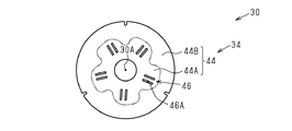
図5に示されるとおり、第1の内周部44は、自転車用ディスクブレーキローター30の放熱性が高められるように加工された円盤であり、第1の部分44A、第2の部分44B、および、第1の冷却促進部46を含む。第1の部分44Aは、第1の外周部42の第1の孔42Bから露出し、第1の方向D1から見て取付部材60の連結部64とオーバーラップする。第1の内周部44は、第1の方向D1から見て外周部32と部分的にオーバーラップする。具体的には、第1の内周部44の第2の部分44Bは、第1の外周部42と接合され、第1の方向D1から見て第1の外周部42とオーバーラップする。
As shown in FIG. 5, the first inner
第1の冷却促進部46は、自転車用ディスクブレーキローター30の放熱性を高めるために設けられる部分であり、第1の開口46A(図5および図8参照)を含む。一例では、第1の開口46Aはスリットである。
The first
図6に示されるとおり、第2の外周部52は、第2のブレーキ面52Aおよび第2の孔52Bを含む。第2のブレーキ面52Aは、ブレーキパッドが押し付けられる面である。第2の孔52Bは、第2の内周部54を露出させるために設けられる。第2の連結部52Cは、取付部材60と連結される部分であり、回転中心軸心30Aに関する径方向において第2の外周部52側から回転中心軸心30A側に向けて突き出た形状を有する。締結部材36は、連結部64の端部を第2の連結部52Cに固定する。
As shown in FIG. 6, the second outer
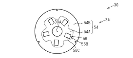
図7に示されるとおり、第2の内周部54は、自転車用ディスクブレーキローター30の放熱性が高められるように加工された円盤であり、第3の部分54A、第4の部分54B、および、第2の冷却促進部56を含む。第2の冷却促進部56は、放熱フィン56Bを含む。第3の部分54Aは、第2の外周部52の第2の孔52Bから露出し、第1の方向D1から見て取付部材60の連結部64とオーバーラップする。放熱フィン56Bは、回転中心軸心30Aに関する周方向(以下「第3の方向D3」)において、少なくとも2つの連結部64の間に設けられ、第2の方向D2においてハブ取付部62と第2の外周部52との間に設けられる。第2の内周部54は、第1の方向D1から見て外周部32と部分的にオーバーラップする。具体的には、第4の部分54Bは、第2の外周部52と接合され、第1の方向D1から見て第2の外周部52とオーバーラップする。第2の冷却促進部56は、第1の開口46Aとは異なる第2の開口56Aを含む。第2の開口56Aの面積は、第1の開口46Aの面積よりも広い。放熱フィン56Bは放熱片56Cを含む。一例では、第2の内周部54に設けられる放熱フィン56Bの数は5つである。第2の開口56Aおよび放熱片56Cは、第2の内周部54を部分的に曲げ加工することにより形成された部分である。一例では、放熱片56Cは第2の方向D2において第2の外周部52側に向けて開口する。
As shown in FIG. 7, the second inner
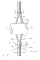
図8に示されるとおり、第1の内周部44および第2の内周部54は、第1の方向D1に関して対向するように配置される。第1の内周部44の第2の部分44Bと、第2の内周部54の第4の部分54Bとは接合されている。
As shown in FIG. 8, the first inner
第1の内周部44の第1の部分44Aおよび第2の内周部54の第3の部分54Aは、第1の方向D1において自転車用ディスクブレーキローター30の外側に脹らむように構成されている。このため、第1の方向D1において対向する第1の内周部44と第2の内周部54との間に空間30Bが形成される。第1の内周部44の第1の開口46Aは、自転車用ディスクブレーキローター30の外部と空間30Bとを連通する。第1の方向D1に関する第1の内周部44と、第2の内周部54との間の距離Lは、第2の方向D2に関して自転車用ディスクブレーキローター30の外側から回転中心軸心30Aに近づくにつれて長くなる。
The
図2〜図7を参照して、自転車用ディスクブレーキローター30の製造方法の一例について説明する。
第1の工程では、アルミニウムまたはアルミニウム合金の材料が加工され、第1の冷却促進部46を含まない第1の内周部44、および、第2の冷却促進部56を含まない第2の内周部54が形成される。第2の工程では、第1の内周部44および第2の内周部54の外面の全体にアルマイト被膜が形成される。第3の工程では、第1の内周部44の第1の部分44Aおよび第2の内周部54の第3の部分54Aのそれぞれにマスキング加工が施される。第4の工程では、第1の内周部44の第2の部分44Bおよび第2の内周部54の第4の部分54Bのアルマイト被膜が除去される。第1の工程から第4の工程が実施されることにより、第1の部分44Aにアルマイト被膜が形成され、第2の部分44Bにアルマイト被膜が形成されていない第1の内周部44、および、第3の部分54Aにアルマイト被膜が形成され、第4の部分54Bにアルマイト被膜が形成されていない第2の内周部54が形成される。
With reference to FIGS. 2-7, an example of the manufacturing method of the
In the first step, a material of aluminum or aluminum alloy is processed, and the first inner
第5の工程では、ステンレス鋼の材料が加工され、第1の外周部42および第2の外周部52が形成される。第6の工程では、第1の外周部42に第1の孔42Bを形成するためのエッチング加工が第1の外周部42に施され、第2の外周部52に第2の孔52Bを形成するためのエッチング加工が第2の外周部52に施される。なお、第5の工程および第6の工程は、第1の工程から第4の工程と並行して、または、第1の工程から第4の工程よりも先に実施可能である。
In the fifth step, the stainless steel material is processed to form the first outer
第7の工程では、第1の方向D1において第1の外周部42、第1の内周部44、第2の内周部54、および、第2の外周部52の順に各部材が並べられ、第1の内周部44の第2の部分44Bと第2の内周部54の第4の部分54Bとが重ねられる。第8の工程では、第1の外周部42、第1の内周部44の第2の部分44B、第2の内周部54の第4の部分54B、および、第2の外周部52が接合される。接合のための手段の一例は拡散接合である。ここで、第1の部分44Aの外面および第3の部分54Aの外面は、アルマイト被膜が形成されているため、第1の外周部42および第2の外周部52と接合されない。
In the seventh step, the respective members are arranged in the order of the first outer
第9の工程では、第1の外周部42の中心側の部分が剥離され、第1の外周部42に第1の孔42Bが形成される。これにより、第1の内周部44の第1の部分44Aが露出する。第13の工程では、第2の外周部52の中心側の部分が剥離され、第2の外周部52に第2の孔52Bが形成される。これにより、第2の内周部54の第3の部分54Aが露出する。
In the ninth step, the central portion of the first outer
第10の工程では、第1の内周部44に第1の開口46Aが形成される。第11の工程では、放熱片56Cを形成するための切り込みが第2の内周部54に形成される。第12の工程では、第1の内周部44の第1の部分44Aおよび第2の内周部54の第3の部分54Aが第1の方向D1において自転車用ディスクブレーキローター30の外側に脹らむように曲げ加工される。なお、第10の工程から第12の工程を実施する順序は任意に変更できる。
In the tenth step, the
第13の工程では、第2の内周部54に放熱片56Cが形成されるように第2の内周部54が曲げ加工される。第14の工程では、第1の外周部42および第2の外周部52のそれぞれに締結部材36を挿入するための孔が形成される。第15の工程では、締結部材36により取付部材60が第1の外周部42および第2の外周部52と結合される。なお、第14の工程および第15の工程は、第13の工程よりも前に実施することができる。
In the thirteenth step, the second inner
自転車用ディスクブレーキローター30によれば以下の作用および効果が得られる。
第1の内周部44および第2の内周部54は、回転中心軸心30Aと平行な軸方向に関して対向するように配置されている。この構成によれば、第1の内周部44における第2の内周部54と対向する面、および、第2の内周部54における第1の内周部44と対向する面は、自転車用ディスクブレーキローター30の熱を空間30Bの空気に放熱できる。このように、自転車用ディスクブレーキローター30は効率的に放熱可能な面の面積が広いため、高い放熱性を有する。
According to the bicycle
The first inner
第1の内周部44は、軸方向から見て第1の外周部42と部分的にオーバーラップした部分において第1の外周部42と接触する。この構成によれば、第1の外周部42の外径を広げることなく第1の内周部44と第1の外周部42との接触面積を広げることができる。なお、第2の内周部54および第2の外周部52についても同様の効果が得られる。
The first inner
第2の開口56Aおよび放熱片56Cは、第2の内周部54を部分的に曲げ加工することにより形成された部分である。この構成によれば、1つの工程で第2の冷却促進部56を構成する2つの機能的部分が第2の内周部54に形成される。このため、第2の冷却促進部56の形成に関する作業効率が高められる。
The
第1の冷却促進部46は、第1の開口46Aを含む。この構成によれば、自転車用ディスクブレーキローター30の外部の空気が第1の開口46Aを介して空間30Bに流れる。このため、第1の内周部44における熱交換が促進されやすい。
The first
第2の冷却促進部56は、第1の開口46Aとは異なる第2の開口56Aを含む。この構成によれば、自転車用ディスクブレーキローター30の外部の空気が第2の開口56Aを介して空間30Bに流れる。このため、第2の内周部54における熱交換が促進されやすい。
The second
軸方向において対向する第1の内周部44および第2の内周部54は、それぞれ第1の開口46Aおよび第2の開口56Aを含む。この構成によれば、自転車用ディスクブレーキローター30の外部、第1の開口46Aおよび第2の開口56Aの一方、空間30B、第1の開口46Aおよび第2の開口56Aの他方、および、自転車用ディスクブレーキローター30の外部の順に空気が流れやすい。このため、自転車用ディスクブレーキローター30の外部の空気が空間30Bに効率的に供給され、自転車用ディスクブレーキローター30の放熱性がより高められる。
The first inner
(変形例)
上記実施の形態に関する説明は本発明に従う自転車用ディスクブレーキローターが取り得る形態の例示であり、その形態を制限することを意図していない。本発明に従う自転車用ディスクブレーキローターは実施の形態以外に例えば以下に示される上記実施の形態の変形例、および、相互に矛盾しない少なくとも2つの変形例が組み合わせられた形態を取り得る。
(Modification)
The above description of the embodiment is an exemplification of a possible form of the bicycle disc brake rotor according to the present invention, and is not intended to limit the form. In addition to the embodiment, the bicycle disc brake rotor according to the present invention may take a form in which, for example, the modifications of the above-described embodiment described below and at least two modifications not contradicting each other are combined.
・自転車用ディスクブレーキローター30を構成する要素は、任意に変更可能である。一例では、自転車用ディスクブレーキローター30は、図9に示される第3の内周部70をさらに備える。第3の内周部70は、少なくとも1つの外周部32と結合し、第1の方向D1において第1の内周部44と第2の内周部54との間に配置され、第2の方向D2において外周部32よりも内側に配置される部分を含む。この構成によれば、自転車用ディスクブレーキローター30において効率的に放熱可能な面の面積が広げられ、自転車用ディスクブレーキローター30の放熱性がより高められる。
The elements constituting the bicycle
・第3の内周部70の構成は、任意に変更可能である。一例では、第3の内周部70は、第1の内周部44に設けられる第1の冷却促進部46と同様の冷却促進部、および、第2の内周部54に設けられる第2の冷却促進部56と同様の冷却促進部の少なくとも一方を含む。
-The structure of the 3rd inner peripheral part 70 can be changed arbitrarily. In one example, the third inner peripheral portion 70 includes a cooling promoting portion similar to the first
・放熱フィン56Bの構成は、任意に変更可能である。一例では、放熱フィン56Bは第3の方向D3に向けて開口する。放熱フィン56Bの開口方向に限らず、放熱フィン56Bの数および形成位置を変更することもできる。
-The structure of the
・締結部材36は、任意に変更可能である。第1の例では、締結部材36は、連結部64の端部を第1の連結部42Cに固定する接着剤である。第2の例では、締結部材36は、連結部64の端部と第1の連結部42Cとが接合されるように溶接された部分である。
The
・外周部32を構成する材料は任意に変更可能である。一例では、第1の外周部42および第2の外周部52の一方が第1の材料を含み、第1の外周部42および第2の外周部52の他方が第1の材料とは異なる材料を含む。
-The material which comprises the outer
・内周部34を構成する材料は、任意に変更可能である。一例では、第1の内周部44および第2の内周部54の一方が第2の材料を含み、第1の内周部44および第2の内周部54の他方が第2の材料とは異なる材料を含む。
-The material which comprises the inner
・自転車用ディスクブレーキローター30の外周部32に関する構成は、少なくとも1つの外周部32を含む任意の構成に変更可能である。一例では、自転車用ディスクブレーキローター30は、第1の外周部42および第2の外周部52の一方を含み、他方を含まない。
The configuration related to the outer
・自転車用ディスクブレーキローター30の内周部34に関する構成は、少なくとも1つの内周部34を含む任意の構成に変更可能である。一例では自転車用ディスクブレーキローター30は、第1の内周部44および第2の内周部54の一方を含み、他方を含まない。
The configuration related to the inner
・自転車用ディスクブレーキローター30の放熱性の向上に関する構成は、少なくとも1つの冷却促進部を含む任意の構成に変更可能である。一例では、自転車用ディスクブレーキローター30は、第1の冷却促進部46および第2の冷却促進部56の一方を含み、他方を含まない。
-The structure regarding the improvement of the heat dissipation of the bicycle
・自転車用ディスクブレーキローター30の制動に関する構成は、少なくとも1つのブレーキ面を含む任意の構成に変更可能である。一例では、自転車用ディスクブレーキローター30は、第1のブレーキ面42Aおよび第2のブレーキ面52Aの一方を含み、他方を含まない。
The configuration related to braking of the bicycle
・自転車用ディスクブレーキローター30は、少なくとも1つのブレーキ面に付着した水および泥等の異物を除去するための除去構造をさらに含むことができる。第1の例では、除去構造は、第1の外周部42、第1の内周部44、第2の内周部54、および、第2の外周部52を貫通する少なくとも1つの孔を含む。第2の例では、除去構造は、第1の外周部42を貫通する少なくとも1つの孔、および、第2の外周部52を貫通する少なくとも1つの孔の一方または両方を含む。第3の例では、除去構造は、第1の例に示される孔および第2の例に示される孔の両方を含む。
The bicycle
10…自転車、18…ハブ、30…自転車用ディスクブレーキローター、30A…回転中心軸心、30B…空間、32…外周部、34…内周部、42…第1の外周部、42A…第1のブレーキ面、42C…第1の連結部、44…第1の内周部、46…第1の冷却促進部、46A…第1の開口、52…第2の外周部、52A…第2のブレーキ面、54…第2の内周部、56…第2の冷却促進部、56A…第2の開口、56B…放熱フィン、56C…放熱片、60…取付部材、62…ハブ取付部、64…連結部、70…第3の内周部、L…距離。
DESCRIPTION OF
Claims (20)
少なくとも1つのブレーキ面を含む少なくとも1つの外周部と、
前記少なくとも1つの外周部と結合し、前記外周部に対して前記回転中心軸心に関する径方向内側に少なくとも一部が配置される第1の内周部および第2の内周部と、を備え、
前記第1の内周部および前記第2の内周部は、前記回転中心軸心と平行な軸方向に関して前記第1の内周部と前記第2の内周部との間に空間が形成されるように配置され、
前記第1の内周部および前記第2の内周部の少なくとも一方は、前記空間と連通する少なくとも1つの開口を含む少なくとも1つの冷却促進部を含む、自転車用ディスクブレーキローター。 A disc brake rotor for a bicycle including a rotation center axis,
At least one outer periphery including at least one brake surface;
A first inner peripheral portion and a second inner peripheral portion, which are coupled to the at least one outer peripheral portion, and at least a part of which is disposed radially inward relative to the outer peripheral portion with respect to the rotation center axis. ,
The first inner peripheral portion and the second inner peripheral portion form a space between the first inner peripheral portion and the second inner peripheral portion with respect to an axial direction parallel to the rotation center axis. Arranged to be
The bicycle disc brake rotor, wherein at least one of the first inner peripheral portion and the second inner peripheral portion includes at least one cooling promoting portion including at least one opening communicating with the space.
前記少なくとも1つの放熱フィンは、前記回転中心軸心に関する周方向において、前記少なくとも2つの連結部の間に設けられる、請求項9に記載の自転車用ディスクブレーキローター。 The mounting member further includes at least two coupling portions that are coupled to the at least one outer peripheral portion and extend radially outward from the hub mounting portion,
The bicycle disc brake rotor according to claim 9, wherein the at least one radiating fin is provided between the at least two connecting portions in a circumferential direction with respect to the rotation center axis.
前記第1の内周部および前記第2の内周部は、前記回転中心軸心と平行な軸方向から見て前記少なくとも2つの連結部とオーバーラップする、請求項7〜9のいずれか一項に記載の自転車用ディスクブレーキローター。 The mounting member further includes at least two coupling portions that are coupled to the at least one outer peripheral portion and extend radially outward from the hub mounting portion,
The first inner peripheral portion and the second inner peripheral portion overlap with the at least two connecting portions as viewed from an axial direction parallel to the rotation center axis. The disc brake rotor for bicycles as described in the paragraph.
前記第1の内周部は、前記第1の冷却促進部を含み、
前記第2の内周部は、前記第2の冷却促進部を含む、請求項1〜11のいずれか一項に記載の自転車用ディスクブレーキローター。 The at least one cooling promotion part includes a first cooling promotion part and a second cooling promotion part,
The first inner peripheral portion includes the first cooling promotion portion,
The bicycle disc brake rotor according to any one of claims 1 to 11, wherein the second inner peripheral portion includes the second cooling promotion portion.
前記第1の内周部および前記第2の内周部は、前記第1の材料とは異なる第2の材料を含む、請求項1〜17のいずれか一項に記載の自転車用ディスクブレーキローター。 The at least one outer periphery includes a first material;
18. The bicycle disc brake rotor according to claim 1, wherein the first inner peripheral portion and the second inner peripheral portion include a second material different from the first material. .
前記第2の材料は、アルミニウムまたはアルミニウム合金である、請求項18に記載の自転車用ディスクブレーキローター。 The first material is stainless steel;
The bicycle disc brake rotor according to claim 18, wherein the second material is aluminum or an aluminum alloy.
前記第3の内周部は、前記回転中心軸心に関する軸方向において、前記第1の内周部と前記第2の内周部との間に配置される、請求項1〜19のいずれか一項に記載の自転車用ディスクブレーキローター。 A third inner peripheral portion that includes a portion that is coupled to the at least one outer peripheral portion and that is disposed radially inward relative to the outer peripheral portion with respect to the rotation center axis;
The third inner peripheral portion is disposed between the first inner peripheral portion and the second inner peripheral portion in the axial direction with respect to the rotation center axis. The disc brake rotor for bicycles according to one item.
Priority Applications (5)
| Application Number | Priority Date | Filing Date | Title |
|---|---|---|---|
| JP2016006311A JP2017125594A (en) | 2016-01-15 | 2016-01-15 | Disc brake rotor for bicycle |
| TW105141424A TWI696772B (en) | 2016-01-15 | 2016-12-14 | Disc brake disc for bicycle |
| DE102016015334.2A DE102016015334A1 (en) | 2016-01-15 | 2016-12-21 | Bicycle disc brake rotor |
| US15/399,316 US10132371B2 (en) | 2016-01-15 | 2017-01-05 | Bicycle disc brake rotor |
| CN201710019429.9A CN107042861B (en) | 2016-01-15 | 2017-01-11 | Bicycle disc brake rotor |
Applications Claiming Priority (1)
| Application Number | Priority Date | Filing Date | Title |
|---|---|---|---|
| JP2016006311A JP2017125594A (en) | 2016-01-15 | 2016-01-15 | Disc brake rotor for bicycle |
Publications (1)
| Publication Number | Publication Date |
|---|---|
| JP2017125594A true JP2017125594A (en) | 2017-07-20 |
Family
ID=59255783
Family Applications (1)
| Application Number | Title | Priority Date | Filing Date |
|---|---|---|---|
| JP2016006311A Pending JP2017125594A (en) | 2016-01-15 | 2016-01-15 | Disc brake rotor for bicycle |
Country Status (5)
| Country | Link |
|---|---|
| US (1) | US10132371B2 (en) |
| JP (1) | JP2017125594A (en) |
| CN (1) | CN107042861B (en) |
| DE (1) | DE102016015334A1 (en) |
| TW (1) | TWI696772B (en) |
Cited By (1)
| Publication number | Priority date | Publication date | Assignee | Title |
|---|---|---|---|---|
| WO2019003650A1 (en) | 2017-06-27 | 2019-01-03 | キヤノン株式会社 | Printing system, printing device and information processing device and method for controlling same, and storage medium |
Families Citing this family (3)
| Publication number | Priority date | Publication date | Assignee | Title |
|---|---|---|---|---|
| TWI644740B (en) * | 2017-12-19 | 2018-12-21 | 至興精機股份有限公司 | Method for manufacturing a floating disk including a forged workpiece |
| DE102018112582A1 (en) * | 2018-05-25 | 2019-11-28 | Shimano Inc. | DISC BRAKE ROTOR |
| JP7117261B2 (en) * | 2019-03-22 | 2022-08-12 | サンスター技研株式会社 | rotation transmission disc |
Family Cites Families (13)
| Publication number | Priority date | Publication date | Assignee | Title |
|---|---|---|---|---|
| JP2005030565A (en) * | 2003-07-11 | 2005-02-03 | Shimano Inc | Disk rotor for bicycle |
| DE102005033765A1 (en) | 2005-07-15 | 2007-01-18 | Gustav Magenwirth Gmbh & Co. Kg | Brake disk for motor vehicle or bicycle, has opposing stopper plates to provide limited axial play to outer ring while mounted to brake hub |
| US8522931B2 (en) * | 2010-03-30 | 2013-09-03 | Shimano Inc. | Disk brake rotor |
| US20120048661A1 (en) * | 2010-08-24 | 2012-03-01 | Ashima Ltd. | Abrasion-resistant disc brake rotor |
| TWI398373B (en) * | 2010-11-10 | 2013-06-11 | Ashima Ltd | Wear discs |
| US9777784B2 (en) * | 2011-03-02 | 2017-10-03 | Shimano, Inc. | Disk brake rotor with hollow portions |
| US20130075207A1 (en) * | 2011-09-22 | 2013-03-28 | Rodney Don BRUNTZ | Brake rotor and method for making same |
| US8978842B2 (en) * | 2011-11-24 | 2015-03-17 | Shimano Inc. | Bicycle disc brake rotor |
| US9234553B2 (en) | 2011-12-29 | 2016-01-12 | Shimano Inc. | Bicycle brake disc |
| CN103434600A (en) * | 2013-07-15 | 2013-12-11 | 温芫鋐 | brake disc |
| US9206869B2 (en) | 2013-08-05 | 2015-12-08 | Yuan-Hung WEN | Brake disk |
| JP2016006311A (en) | 2014-06-20 | 2016-01-14 | 日立建機株式会社 | Diesel engine exhaust emission control system and diesel engine exhaust emission control method |
| US9593727B1 (en) * | 2015-10-06 | 2017-03-14 | Shimano Inc. | Bicycle disc brake rotor |
-
2016
- 2016-01-15 JP JP2016006311A patent/JP2017125594A/en active Pending
- 2016-12-14 TW TW105141424A patent/TWI696772B/en active
- 2016-12-21 DE DE102016015334.2A patent/DE102016015334A1/en active Pending
-
2017
- 2017-01-05 US US15/399,316 patent/US10132371B2/en active Active
- 2017-01-11 CN CN201710019429.9A patent/CN107042861B/en active Active
Cited By (2)
| Publication number | Priority date | Publication date | Assignee | Title |
|---|---|---|---|---|
| WO2019003650A1 (en) | 2017-06-27 | 2019-01-03 | キヤノン株式会社 | Printing system, printing device and information processing device and method for controlling same, and storage medium |
| EP4530818A2 (en) | 2017-06-27 | 2025-04-02 | Canon Kabushiki Kaisha | Printing system, method of controlling a printing system, and computer program product |
Also Published As
| Publication number | Publication date |
|---|---|
| DE102016015334A1 (en) | 2017-07-20 |
| CN107042861B (en) | 2020-01-21 |
| CN107042861A (en) | 2017-08-15 |
| US10132371B2 (en) | 2018-11-20 |
| TW201727095A (en) | 2017-08-01 |
| TWI696772B (en) | 2020-06-21 |
| US20170204923A1 (en) | 2017-07-20 |
Similar Documents
| Publication | Publication Date | Title |
|---|---|---|
| TWI554430B (en) | Bicycle disc brake rotor | |
| US8978842B2 (en) | Bicycle disc brake rotor | |
| US8522931B2 (en) | Disk brake rotor | |
| TWI663343B (en) | Heat dissipating brake rotor | |
| JP2017125594A (en) | Disc brake rotor for bicycle | |
| US8881873B2 (en) | Bicycle disc brake rotor | |
| TWI714795B (en) | Bicycle disc brake rotor | |
| US9593727B1 (en) | Bicycle disc brake rotor | |
| US9725131B2 (en) | Bicycle disc brake rotor | |
| TWI717618B (en) | Disc brake rotating parts | |
| US20140231196A1 (en) | Brake disc with enhanced heat dissipation | |
| US10711857B2 (en) | Bicycle disc brake rotor | |
| US10323704B2 (en) | Bicycle brake disc | |
| US8813921B2 (en) | Bicycle disc brake rotor | |
| US20130133994A1 (en) | Bicycle disc brake rotor | |
| JP4507437B2 (en) | brake disc | |
| CN212509296U (en) | Servant brake assembly and riding vehicle | |
| TWI717614B (en) | Disc brake rotor | |
| TWI751388B (en) | Disc brake rotor | |
| TWM529781U (en) | Brake disc | |
| TWM519194U (en) | Brake disc with heat dissipation structure |