JP2017127426A - Mail receiving box - Google Patents
Mail receiving box Download PDFInfo
- Publication number
- JP2017127426A JP2017127426A JP2016008039A JP2016008039A JP2017127426A JP 2017127426 A JP2017127426 A JP 2017127426A JP 2016008039 A JP2016008039 A JP 2016008039A JP 2016008039 A JP2016008039 A JP 2016008039A JP 2017127426 A JP2017127426 A JP 2017127426A
- Authority
- JP
- Japan
- Prior art keywords
- opening
- box
- door
- receiving box
- closing door
- Prior art date
- Legal status (The legal status is an assumption and is not a legal conclusion. Google has not performed a legal analysis and makes no representation as to the accuracy of the status listed.)
- Pending
Links
Images





Landscapes
- Supports Or Holders For Household Use (AREA)
Abstract
Description
本発明は、ポストなどの投函物受け箱に関する。 The present invention relates to a post receiving box such as a post.
マンションや一般住宅などに設けられる投函物受け箱は、例えば、郵便物などの投函物を投函する投函口、投函物を取り出す取出口の開口を備えたボックス本体(投函箱)と、取出口、投函口などを開閉する開閉扉とを備えて構成したものがある。 For example, a box receiving box provided in a condominium or a general house has a box opening (posting box) with an opening for taking out a mailed item, a box main body (posting box) with an opening for taking out the post, Some have a door that opens and closes a mailing slot.
また、取出口(や投函口)を開閉する開閉扉を横方向に延びる回動軸周りに回動するように設け、開閉扉を上下方向に動かして前倒しするように構成した横型の投函物受け箱(例えば、特許文献1、特許文献2参照)がある。
In addition, a horizontal-type throwing receptacle that is configured so that an opening / closing door that opens and closes an outlet (or a throwing opening) is rotated about a rotation shaft that extends in the horizontal direction, and the opening / closing door is moved up and down to move forward. There is a box (see, for example,
ここで、開閉扉を前倒しするように構成した横型の投函物受け箱は、例えば、取出口と投函口、特に取出口を開閉する開閉扉を手で開いて投函物を取り出すように構成されている。 Here, the horizontal type throwing object receiving box configured to move the door forward is configured to, for example, open the door and the opening, particularly the door that opens and closes the door, and take out the throwing object. Yes.
このため、取出口を開く際に片方の手を使い、他方の手で投函物を取り出すことになり、開閉扉の開閉、投函物の取り出しを行う一連の操作性が悪く、この点で改善の余地が残されていた。 For this reason, one hand is used to open the outlet, and the throwing object is taken out with the other hand, and the series of operability for opening and closing the door and taking out the throwing object is poor. There was room left.
本発明は、上記事情に鑑み、操作性に優れた横型の投函物受け箱を提供することを目的とする。 In view of the above circumstances, an object of the present invention is to provide a horizontal throwing object receiving box excellent in operability.
上記の目的を達するために、この発明は以下の手段を提供している。 In order to achieve the above object, the present invention provides the following means.
本発明の投函物受け箱は、投函物を投函するための投函口及び前記投函物を取り出すための取出口が開口形成され、前記投函口から投函した前記投函物を収容するボックス本体と、前記投函物受け箱の幅方向に延びる回動軸周りに回動自在に前記ボックス本体の下端部側に接続し、前記投函口及び/又は前記取出口を前倒し式で開閉するように設けられた開閉扉とを備える横型の投函物受け箱であって、前記開閉扉で前記投函口及び/又は前記取出口を閉じた状態で、前記開閉扉を係止して保持する開閉機構を備え、且つ前記開閉扉の係止状態を解除するための前記開閉機構の操作部が前記ボックス本体の側部に設けられ、該操作部を操作するとともに前記開閉扉が自重によって自動的に開動するように構成されていることを特徴とする。 The throwing object receiving box of the present invention has an opening formed for opening a throwing object and a takeout opening for taking out the throwing object, and a box main body for accommodating the throwing object that has been thrown from the throwing hole, Opening / closing provided to be connected to the lower end side of the box body so as to be rotatable around a rotation axis extending in the width direction of the throwing object receiving box, and to open and close the throwing port and / or the take-out port in a forward-facing manner. A horizontal type throwing object receiving box comprising a door, comprising an opening / closing mechanism that holds and holds the opening / closing door in a state in which the opening / closing door is closed by the opening / closing door; and An operation part of the opening / closing mechanism for releasing the locking state of the opening / closing door is provided on a side part of the box body, and the operation part is operated and the opening / closing door is automatically opened by its own weight. It is characterized by.
また、本発明の投函物受け箱においては、前記開閉扉が、下端部側を前記回動軸と介して前記ボックス本体に回動自在に接続される扉本体部と、前記扉本体部よりも大重量で板状に形成され、前記扉本体部の前面側に接続して設けられて前記投函物受け箱の表面を形成する面材部とを備えていることが望ましい。 Further, in the throwing object receiving box of the present invention, the opening / closing door is pivotally connected to the box body via the rotation shaft on the lower end side, and the door body part than the door body part. It is desirable to include a face material portion that is formed in a plate shape with a large weight and is connected to the front surface side of the door main body portion to form the surface of the throwing object receiving box.
さらに、本発明の投函物受け箱においては、前記面材部が前記扉本体部に着脱可能に取り付けられていることがより望ましい。 Furthermore, in the posting object receiving box of the present invention, it is more desirable that the face material portion is detachably attached to the door body portion.
また、本発明の投函物受け箱においては、前記扉本体部が、前記回動軸を介して前記ボックス本体に回動自在に接続される回動板部と、前記回動板部及び前記面材部よりも表面及び裏面の面積を小にして形成され、前記回動板部と前記面材の間に配設される延出部とを備えて形成されていることがさらに望ましい。 Further, in the throwing object receiving box of the present invention, the door main body is pivotally connected to the box main body via the pivot shaft, the pivot plate and the surface. It is further preferable that the front and back surfaces are formed to be smaller than the material part, and the extension part disposed between the rotating plate part and the face material is formed.
さらに、本発明の投函物受け箱においては、前記操作部を操作するとともに前記ボックス本体の内部に光を照射する照明装置が前記操作部に一体に設けられていることがより望ましい。 Furthermore, in the posting object receiving box of the present invention, it is more preferable that an illuminating device for operating the operation unit and irradiating light inside the box body is provided integrally with the operation unit.
また、本発明の投函物受け箱においては、前記開閉機構が、前記ボックス本体に回動自在に設けられた係止部材と、前記開閉扉に設けられ、前記係止部材が係合し前記開閉扉を閉じた状態で保持するための係止受け部材と、前記係止部材と前記係合受け部材の係合状態を解除するための解錠機構とを備え、前記解錠機構が、前記操作部と、該操作部の操作によって電流が流れて磁界を発生するコイル、及び該コイルで発生した磁界によって移動し、該移動に応じて前記係止部材を回動させる芯材からなるソレノイド機構とを備えて構成されていることが望ましい。 Further, in the throwing object receiving box of the present invention, the opening / closing mechanism is provided on the opening / closing door, and the opening / closing door is provided on the opening / closing door. A locking receiving member for holding the door in a closed state; and an unlocking mechanism for releasing the engagement state of the locking member and the engagement receiving member. And a solenoid mechanism comprising a coil that generates a magnetic field when an electric current flows by operation of the operation unit, and a core member that is moved by the magnetic field generated by the coil and rotates the locking member in accordance with the movement. It is desirable to be configured with.
本発明の投函物受け箱においては、ボックス本体の側部に設けられた操作部を使用者が片手で操作するだけで、自動的に開閉扉を作動させて取出口(及び/又は投函口)を開くことができる。よって、従来と比較し、大幅に操作性、利便性を向上させることが可能になる。 In the throwing object receiving box of the present invention, the user can operate the opening / closing door automatically by simply operating the operation part provided on the side part of the box body with one hand, thereby taking out the outlet (and / or the opening). Can be opened. Therefore, it is possible to greatly improve operability and convenience compared to the conventional case.
また、開閉扉を開閉するための操作部がボックス本体の側部に設けられていることで、開閉扉の前面に設けられた従来の投函物受け箱と比較し、見栄えをよくすることができる。 In addition, since the operation part for opening and closing the door is provided on the side of the box body, it can be improved in appearance compared with the conventional throwing object receiving box provided on the front surface of the door. .
以下、図1から図13を参照し、本発明の一実施形態に係る投函物受け箱について説明する。 Hereinafter, with reference to FIGS. 1 to 13, a throwing object receiving box according to an embodiment of the present invention will be described.
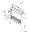
本実施形態の投函物受け箱Aは、図1から図3に示すように、例えば横型のポストであり、矩形箱状に形成され、上面1aに投函口2、前面1bに取出口3がそれぞれ開口形成されたボックス本体(投函箱)1と、ボックス本体1の上面1a側に回動自在に取り付けられて投函口2を開閉する蓋扉(投函口用開閉扉)4と、ボックス本体1の前面1b側に回動自在に取り付けられて取出口3を開閉する取出口用開閉扉5と、取出口用開閉扉5を開閉するための開閉機構6とを備えて構成されている。
As shown in FIG. 1 to FIG. 3, the posting object receiving box A of the present embodiment is, for example, a horizontal post and is formed in a rectangular box shape. A box body (posting box) 1 having an opening, a lid door (opening / closing door) 4 that is pivotally attached to the
投函口2は、ボックス本体1の天板部の上面から内面に貫通し、投函物受け箱Aの幅方向T1に延びる長孔状に形成されている。また、投函口2の外周に沿い、投函口2を囲繞するようにしてボックス本体1の上面1aから上方に突出する投函口枠部7が設けられている。投函口枠部7は、その上端部が投函物受け箱Aの奥行方向T2後方から前方に向かうに従い下方に配されるように傾斜して形成されている。
The
投函口用開閉扉である蓋扉4は、ボックス本体1の上面1aと略同等の平面積を備えた略矩形板状に形成され、長手方向を投函物受け箱Aの幅方向T1に向け、その後端側の両側部側をボックス本体1に設けられた幅方向T1に延びる回動軸に接続して設けられている。これにより、蓋扉4は回動軸周りの上下方向T3に回動自在に設けられている。
The
また、投函口2を閉じてボックス本体1の上部に当接支持された状態で投函物受け箱Aの前面1b側に配される端部を手で押し上げ、回動軸周りに回動させることによって投函口2を開くように構成されている。ボックス本体1の天板部には、ダンパー8が設けられており、開いた状態で手を離し、蓋扉4が回動軸周りに回動して投函口2を閉じるように落下すると、ダンパー8によってその閉動速度が調節され、ゆっくりと回動して閉じるように構成されている。
In addition, with the
一方、取出口用開閉扉5は、ボックス本体1の底部側の前面側に設けられて幅方向T1に延びる回動軸に下端部側を接続し、回動軸の回動軸線周りに回動することによって取出口3を開閉するように設けられている。すなわち、本実施形態の取出口用開閉扉5は、下端部側の回動軸周りに回動する前倒し式の開閉扉とされている。
On the other hand, the exit opening /
さらに、本実施形態の取出口用開閉扉5は、下端部側を回動軸に接続して回動自在に設けられた平面視略方形状の扉本体部10と、扉本体部10の前面に着脱可能に取り付けられて投函物受け箱Aの前面(表面)を形成する方形平板状の面材部11とを備えて構成されている。
Furthermore, the opening / closing
面材部11は、取出口用開閉扉5の重心が回動軸から前方に離間して偏心するように扉本体部10の重量よりも大きな重量を備えて形成されている。
The
扉本体部10は、回動軸を介してボックス本体1に回動自在に接続される回動板部10aと、回動板部10a及び面材部11よりも表面及び裏面の面積を小にして形成され、回動板部10aと面材部11の間に配設される延出部10bとを備えて形成されている。
The door
延出部10bは、その上面10cが例えば幅方向T1中央から幅方向T1両側部側に向かうに従い下方に傾斜し、投函物受け箱Aの側部側に流れ、延出部10bの上面10cに雨水等が溜まらないように形成されている。
The extending
このように構成した取出口用開閉扉5は、取出口3を閉じた状態で開閉機構6による係止状態が解除されると、重心が前方に偏心しているため、自重によって自動的に回動軸周りに回動し、取出口3を開く。
The outlet opening / closing
また、ボックス本体1の底部にダンパー12が設けられ、このダンパー12によって取出口用開閉扉5が開動する際にその開動速度が調節され、急激に開くことが防止されている。
Also, a
次に、開閉機構6は、図2から図7に示すように、取出口用開閉扉5を係止して保持する(施錠する)ための施錠機構20と、取出口用開閉扉5の係止状態を解除する(解錠するため)の解錠機構30とを備えている。
Next, as shown in FIGS. 2 to 7, the opening /
施錠機構20は、ボックス本体1の上端部側の幅方向T1略中央に、上下方向T3に延びる回転軸に後端部側を回転可能に軸支して設けられ、ボックス本体1の前面1bから前方に突出し、その突出方向先端側に鉤状部21aを有するラッチ(係止部材)21と、取出口用開閉扉5の扉本体部10の上端部側の幅方向T1略中央に設けられ、取出口用開閉扉5を閉じるともにラッチ21に係合して取出口用開閉扉5を閉じた状態で保持するためのラッチ受け(係合受け部材)22と、ラッチ21、ひいては回転軸を軸線周りの一方向に回動させるように付勢するバネ部材(弾性部材)23とを備えている。
The locking mechanism 20 is provided at approximately the center in the width direction T1 on the upper end portion side of the
また、ラッチ21の鉤状部21aの先端側には、先端から後端側に向かうに従い漸次外側に離れるように傾斜する当接面21bが設けられている。これにより、取出口用開閉扉5の閉動作時にラッチ受け22が当接面21bに当接すると、ラッチ21が他方向に回転し、完全に取出口用開閉扉5が閉じるとともに当接状態が解除され、自動的にラッチ21とラッチ受け22を係合させることができる。
Further, a
解錠機構30は、ソレノイド機構31と、ソレノイド機構31を駆動させるための操作部32とを備えている。
The unlocking mechanism 30 includes a
ソレノイド機構31は、電流を流すことにより磁界を発生するコイルと、コイルで発生した磁界によって前後方向に移動する芯材(鉄芯)31aとを備えている。
The
また、ソレノイド機構31は、ボックス本体1の上端部の略中央に一体に設けられるとともに、芯材32aの先端側をラッチ21の後端側に接続して配設されている。さらに、コイルに電流が流れていない状態では、ラッチ21とともにバネ部材23に付勢されて芯材32aがコイルに対して前方に進出した状態で保持されている。
In addition, the
ソレノイド機構31は、電源33から電力が供給されてコイルに電流が流れると、芯材32aが後方に退避し、バネ部材23の付勢力に反してラッチ21を回転軸周りの一方向に回動させ、ラッチ21とラッチ受け22の係合状態を解除するように構成されている。
In the
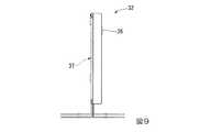
操作部32は、例えばタッチパネル式の操作部であり、図8、図9に示すように、複数の数字(本実施形態では「1」、「2」、「3」、「4」)を表示する暗証番号キー35と、作動キー(作動ボタン)36とを備えている。本実施形態の操作部32は、図1から図5に示すように、ボックス本体1の前面1b側の側面1cに、タッチパネル面が側面1cに沿うようにして取り付けられている。
The
この操作部32は、図4、図7、図9に示すように、ボックス本体1の内面に露出する裏面側に、LEDなどの光源を備えた照明装置37が内蔵して設けられるとともに、電池ボックス(電源33)が配線接続して一体に設けられている。なお、操作部32とソレノイド機構31のコイルは、ボックス本体1に形成された配線路(配線孔)40を通じて配線で接続されている。
As shown in FIGS. 4, 7, and 9, the
そして、予め記憶された操作部32の暗証番号キーが適正に操作された後、作動キー36を操作すると、すなわち、操作部32の解錠操作を行うと、リミットスイッチ38によって電源33からソレノイド機構31のコイルに一定時間電流が流れるように構成されている。
When the
また、操作部32の解錠操作を行うと、電源33から照明装置37に電力が供給され、照明装置37の光源が光り、ボックス本体1の内部を自動的に明るく照らすように構成されている。なお、タイマーを設け、必要な時間(例えば5秒間)、光を照射した後、自動的に消灯するように構成してもよい。
When the unlocking operation of the
さらに、本実施形態の投函物受け箱Aにおいては、電池が消耗し、蓄電量がある一定レベルまで減少した際に、照明装置37の光源を点滅させるなどし、電池交換時期であることを知らせるように構成されている。なお、この照明装置37の光が操作部32のタッチパネル面から外部に照射されるようにし、光源の点滅などが投函物受け箱Aの外部からでも認識できるようにしてもよい。
Further, in the throwing object receiving box A of the present embodiment, when the battery is consumed and the storage amount is reduced to a certain level, the light source of the illuminating
上記のように構成した本実施形態の投函物受け箱Aに投函物を投函する際には、蓋扉4を手で押し上げて回動させ、露出した投函口2から投函物をボックス本体1内に投入する。そして、蓋扉4を離すと、自動的に蓋扉4が落下して閉動するとともにダンパー8によってゆっくりと投函口2を閉じる。
When throwing a throwing object into the throwing object receiving box A of the present embodiment configured as described above, the
次に、投函物受け箱A内の投函物の有無を確認したり、投函物受け箱Aから投函物を取り出す際には、使用者が操作部32の作動キー(電源ボタン)36を押すとタッチパネルの暗証番号キー35が点灯し、暗証番号キー35を操作して適正な暗証番号を入力し、作動キー36を操作する。
Next, when checking the presence or absence of a throwing thing in the throwing thing receiving box A or taking out the throwing thing from the throwing thing receiving box A, the user presses the operation key (power button) 36 of the
ここで、電池が消耗している場合には、作動キー(電源ボタン)36を押すと、暗証番号キー35が点滅することによって電池交換時期を知らせるようにしてもよい。また、この状態でも暗証番号キー35を操作して解錠することができ、この解錠操作を行って取出側開閉扉5が開いた際に照明装置37の光が必要な時間点滅するようにしてもよい。
Here, when the battery is exhausted, when the operation key (power button) 36 is pressed, the password key 35 may blink to notify the battery replacement time. Even in this state, the personal
この操作がなされると、操作部32からの信号によって電源33からソレノイド機構31のコイルにそれぞれ電流が一定時間流れ、ソレノイド機構31の芯材31aが後方に退避移動する。このソレノイド機構31の芯材31aが退避すると、これとともにラッチ21が回転軸の軸線周りの他方向に回転し、ラッチ21と取出口用開閉扉5のラッチ受け22との係合状態が解除される。すなわち、自動的に取出口用開閉扉5が解錠される。
When this operation is performed, a current flows from the
なお、一定時間経過した段階で電源33からコイルへの給電が停止する。給電が停止すると、バネ部材23の付勢力によって芯材31aが前方に進出するとともにラッチ21が軸線周りの一方向に回転して、これら芯材31aとラッチ21がそれぞれ元の位置に戻る。
Note that the power supply from the
また、本実施形態の取出口用開閉扉5は、扉本体部10(回動板部10a、延出部10b)と面材部11からなり、扉本体部10の重量よりも面材部11が大重量で、重心が前方に偏心され、且つ扉本体部10の下端部側をボックス本体Aの側部の底部側に回動自在に接続して設けられている。
The outlet opening /
このため、操作部32を操作して取出口用開閉扉5が解錠されるとともに、その重心が前方に偏心されていることによって自動的に取出口用開閉扉5が開く。また、ボックス本体1内に設けられたダンパー12によって取出口用開閉扉5の開動速度が調整され、ゆっくりと取出口3が開くことになる。
For this reason, the opening /
また、このとき、操作部32を解錠操作するとともに、照明装置37の光源が光り、ボックス本体1の内部を自動的に明るく照らされる。
At this time, the
そして、使用者は、取出口用開閉扉5が開いて開口した取出口3から投函物を取り出すことができる。
And a user can take out a throwing thing from the
次に、投函物を取り出した後、使用者が取出口用開閉扉5を閉じると、取出口用開閉扉5に設けられたラッチ受け22がラッチ21の鉤状部21aの当接面21bに当接し、ラッチ21が他方向に回転する。そして、取出口用開閉扉5が完全に閉じると、ラッチ受け22の当接状態が解除され、バネ部材23の付勢力によってラッチ21が一方向に回転して元に戻り、ラッチ受け22に係合する。これにより、自動的に取出口用開閉扉5が施錠され、取出口3を閉じた状態で保持される。
Next, when the user closes the outlet opening /
したがって、本実施形態の投函物受け箱Aにおいては、ボックス本体1の側部に設けられた操作部32を使用者が片手で操作するだけで、自動的に開閉扉5を作動させて取出口3を開くことができる。
Therefore, in the throwing object receiving box A of the present embodiment, the opening /
また、開閉扉5を開閉するための操作部32がボックス本体1の側部に設けられていることで、開閉扉5の前面に操作部を設けた従来の投函物受け箱と比較し、見栄えをよくすることができる。
Further, the
さらに、操作部32の解錠操作を行うとともに、照明装置37の光源が光り、ボックス本体1の内部を自動的に明るく照らすことができる。また、タイマーを設けることによって、必要な時間、光を照射した後、自動的に消灯させることができる。
Further, the unlocking operation of the
さらに、電池が消耗し、蓄電量がある一定レベルまで減少した際に、照明装置37の光源を点滅させるなどして電池の電力不足を知らせることができる。
Further, when the battery is exhausted and the amount of stored power is reduced to a certain level, it is possible to notify the battery power shortage by blinking the light source of the
操作部32を取出口用開閉扉5の面材部11ではなくボックス本体1に設けるようにしたことで、面材部11を延出部10bの先端に着脱可能に取り付けることができる。そして、このように面材部11が着脱可能とされていることにより、色が異なる面材部11を選択的に取り付けることができ、且つ、容易に交換することができ、投函物受け箱Aの意匠性、メンテナンス性を向上させることができる。
Since the
また、取出口用開閉扉5を扉本体部10と面材部11で構成し、さらに、扉本体部10が、回動軸を介してボックス本体1に回動自在に接続される回動板部10aと、回動板部10a及び面材部11よりも表面及び裏面の面積を小にして形成され、回動板部10aと面材部11の間に配設される延出部10bとを備えて形成されている。このように回動板部10aと面材部11の間に面積が小さい延出部10bを設け、この延出部10bの部位に凹部が形成されることにより、投函物受け箱Aの見栄えをさらによくすることができる。
Moreover, the opening /
さらに、取出口用開閉扉5の重心を回動軸から離間する前方に偏心することで自動的に開動するように構成したことにより、延出部10bの奥行方向T2の寸法を調整したり、ダンパー12の性能を調整することによって、取出口用開閉扉5の開動速度を自在に且つ容易に調節することが可能になる。
Furthermore, by adjusting the center of gravity of the opening /
よって、本実施形態の投函物受け箱Aによれば、従来と比較し、大幅に操作性、利便性を向上させることが可能になる。 Therefore, according to the posting thing receiving box A of this embodiment, it becomes possible to improve operativity and convenience significantly compared with the past.
以上、本発明に係る投函物受け箱の一実施形態について説明したが、本発明は上記の一実施形態に限定されるものではなく、その趣旨を逸脱しない範囲で適宜変更可能である。 As mentioned above, although one Embodiment of the posting thing receiving box which concerns on this invention was described, this invention is not limited to said one Embodiment, In the range which does not deviate from the meaning, it can change suitably.
例えば、本実施形態では、開閉機構6の解錠機構30がソレノイド機構31とソレノイド機構31を駆動させるためのタッチパネル式の操作部32とで構成されているものとした。
For example, in this embodiment, the unlocking mechanism 30 of the opening /
これに対し、開閉機構6は、図10から図13に示すように、ダイヤル式の操作部41と、操作部41に一端を接続して幅方向T1に延設され、操作部41の手動回転操作に応じて軸線周りに回転する回転軸42と、回転軸42に一体に取り付けられた係合部材(爪部)43と、開閉扉5に設けられ、係合部材43が係合する係合受け部材(受け部)44とを備えて構成してもよい。また、カムロック機構(カムロック錠)等の施錠部45を設け、係合部材43と係合受け部材44が係合した状態で回転軸42を回転不能に保持できるようにしてもよい。この場合においても、大略本実施形態と同等の作用効果を得ることができる。
また、このようにダイヤル式の操作部41を備える場合には、ボックス本体1の両側部にダイヤル式の操作部41を設け、回転軸42の両端を両方の操作部41に接続しておくことで、使用者が左右のどちらの手でも解錠操作することができ、使い勝手がよくなる。
On the other hand, as shown in FIGS. 10 to 13, the opening /
When the dial-
また、前入れ後ろ出し式の投函物受け箱などにおいては、投函口2及び/又は取出口3を開閉する開閉扉に本発明を適用してもよい。
The present invention may be applied to an open / close door that opens and closes the throwing
1 ボックス本体
1a 上面
1b 前面
1c 側面
2 投函口
3 取出口
4 蓋扉(投函口用開閉扉)
5 取出口用開閉扉
6 開閉機構
7 投函口枠部
8 ダンパー
10 扉本体部
10a 回動板部
10b 延出部
10c 上面
11 面材部
12 ダンパー
20 施錠機構
21 ラッチ(係止部材)
21a 鉤状部
21b 当接面
22 ラッチ受け(係合受け部材)
23 バネ部材(弾性部材)
30 解錠機構
31 ソレノイド機構
31a 芯材
32 操作部
33 電源(電池)
35 暗証番号キー
36 作動キー(電源ボタン/作動ボタン)
37 照明装置
38 リミットスイッチ
40 配線路
41 操作部
42 回転軸
43 係合部材(爪部)
44 係合受け部材(受け部)
45 施錠部
A 投函物受け箱
T1 幅方向
T2 奥行方向
T3 上下方向
1
5 Opening /
23 Spring member (elastic member)
30 Unlocking
35
37
44 Engagement receiving member (receiving part)
45 Locking part A Thing box receiving box T1 Width direction T2 Depth direction T3 Vertical direction
Claims (6)
前記開閉扉で前記投函口及び/又は前記取出口を閉じた状態で、前記開閉扉を係止して保持する開閉機構を備え、
且つ前記開閉扉の係止状態を解除するための前記開閉機構の操作部が前記ボックス本体の側部に設けられ、該操作部を操作するとともに前記開閉扉が自重によって自動的に開動するように構成されていることを特徴とする投函物受け箱。 A throwing port for throwing a thrown object and an outlet for taking out the thrown object are formed with an opening, and extends in the width direction of the throwing object receiving box with a box body for accommodating the thrown object thrown from the throwing port. A horizontal throwing object receptacle provided with an opening / closing door that is connected to the lower end side of the box main body so as to be rotatable around a pivot shaft and is provided to open and close the throwing port and / or the outlet in a forward-tilting manner. A box,
An opening / closing mechanism that holds and locks the opening / closing door in a state in which the opening / closing door is closed with the opening / closing door;
An operation portion of the opening / closing mechanism for releasing the locking state of the opening / closing door is provided on a side portion of the box body so that the opening / closing door is automatically opened by its own weight while operating the operation portion. A post receiving box characterized by being constructed.
前記開閉扉が、下端部側を前記回動軸と介して前記ボックス本体に回動自在に接続される扉本体部と、前記扉本体部よりも大重量で板状に形成され、前記扉本体部の前面側に接続して設けられて前記投函物受け箱の表面を形成する面材部とを備えている投函物受け箱。 In the posting box of claim 1,
The open / close door is formed in a plate shape having a weight lower than that of the door main body, the door main body being pivotally connected to the box main body via the rotation shaft at the lower end, and the door main body A throwing object receiving box provided with a face material part which is provided in connection with the front side of the part and forms the surface of the posting object receiving box.
前記面材部が前記扉本体部に着脱可能に取り付けられている投函物受け箱。 In the posting box of claim 2,
A box receiving box in which the face material portion is detachably attached to the door body portion.
前記扉本体部が、前記回動軸を介して前記ボックス本体に回動自在に接続される回動板部と、前記回動板部及び前記面材部よりも表面及び裏面の面積を小にして形成され、前記回動板部と前記面材の間に配設される延出部とを備えて形成されている投函物受け箱。 In the post receiving box according to claim 1 or claim 3,
The door body is pivotably connected to the box body via the pivot shaft, and the front and back areas are smaller than those of the pivot plate and the face material. A throwing object receiving box formed by including an extending portion disposed between the rotating plate portion and the face material.
前記操作部を操作するとともに前記ボックス本体の内部に光を照射する照明装置が前記操作部に一体に設けられている投函物受け箱。 In the throwing object receiving box according to any one of claims 1 to 4,
A throwing object receiving box in which a lighting device for operating the operation unit and irradiating light inside the box body is provided integrally with the operation unit.
前記開閉機構が、前記ボックス本体に回動自在に設けられた係止部材と、前記開閉扉に設けられ、前記係止部材が係合し前記開閉扉を閉じた状態で保持するための係止受け部材と、前記係止部材と前記係合受け部材の係合状態を解除するための解錠機構とを備え、
前記解錠機構が、前記操作部と、該操作部の操作によって電流が流れて磁界を発生するコイル、及び該コイルで発生した磁界によって移動し、該移動に応じて前記係止部材を回動させる芯材からなるソレノイド機構とを備えて構成されている投函物受け箱。 In the throwing object receiving box according to any one of claims 1 to 5,
The opening / closing mechanism is provided in the box body so as to be rotatable, and the locking member is provided in the opening / closing door for engaging the locking member and holding the opening / closing door in a closed state. A receiving member, and an unlocking mechanism for releasing the engagement state of the locking member and the engagement receiving member,
The unlocking mechanism is moved by the operation unit, a coil that generates a magnetic field through the operation of the operation unit, and a magnetic field generated by the coil, and the locking member is rotated according to the movement. A throwing object receiving box configured to include a solenoid mechanism made of a core material.
Priority Applications (1)
| Application Number | Priority Date | Filing Date | Title |
|---|---|---|---|
| JP2016008039A JP2017127426A (en) | 2016-01-19 | 2016-01-19 | Mail receiving box |
Applications Claiming Priority (1)
| Application Number | Priority Date | Filing Date | Title |
|---|---|---|---|
| JP2016008039A JP2017127426A (en) | 2016-01-19 | 2016-01-19 | Mail receiving box |
Publications (1)
| Publication Number | Publication Date |
|---|---|
| JP2017127426A true JP2017127426A (en) | 2017-07-27 |
Family
ID=59395144
Family Applications (1)
| Application Number | Title | Priority Date | Filing Date |
|---|---|---|---|
| JP2016008039A Pending JP2017127426A (en) | 2016-01-19 | 2016-01-19 | Mail receiving box |
Country Status (1)
| Country | Link |
|---|---|
| JP (1) | JP2017127426A (en) |
Cited By (2)
| Publication number | Priority date | Publication date | Assignee | Title |
|---|---|---|---|---|
| JP2019034077A (en) * | 2017-08-21 | 2019-03-07 | 株式会社ナスタ | Storage furniture |
| JP2022085132A (en) * | 2020-11-27 | 2022-06-08 | パナソニックIpマネジメント株式会社 | Mailbox |
Citations (6)
| Publication number | Priority date | Publication date | Assignee | Title |
|---|---|---|---|---|
| JPS5154700U (en) * | 1974-10-22 | 1976-04-26 | ||
| JP2002165696A (en) * | 2000-11-30 | 2002-06-11 | Matsushita Electric Works Ltd | Mailbox with lighting |
| JP2007000613A (en) * | 2005-05-26 | 2007-01-11 | Matsushita Electric Works Ltd | Mailbox |
| JP2008264368A (en) * | 2007-04-24 | 2008-11-06 | Matsushita Electric Works Ltd | Mailbox |
| JP2010077676A (en) * | 2008-09-25 | 2010-04-08 | Panasonic Electric Works Co Ltd | Mechanism for opening/closing door |
| JP3186948U (en) * | 2013-08-21 | 2013-10-31 | 株式会社シャインテック | Mailbox |
-
2016
- 2016-01-19 JP JP2016008039A patent/JP2017127426A/en active Pending
Patent Citations (6)
| Publication number | Priority date | Publication date | Assignee | Title |
|---|---|---|---|---|
| JPS5154700U (en) * | 1974-10-22 | 1976-04-26 | ||
| JP2002165696A (en) * | 2000-11-30 | 2002-06-11 | Matsushita Electric Works Ltd | Mailbox with lighting |
| JP2007000613A (en) * | 2005-05-26 | 2007-01-11 | Matsushita Electric Works Ltd | Mailbox |
| JP2008264368A (en) * | 2007-04-24 | 2008-11-06 | Matsushita Electric Works Ltd | Mailbox |
| JP2010077676A (en) * | 2008-09-25 | 2010-04-08 | Panasonic Electric Works Co Ltd | Mechanism for opening/closing door |
| JP3186948U (en) * | 2013-08-21 | 2013-10-31 | 株式会社シャインテック | Mailbox |
Cited By (4)
| Publication number | Priority date | Publication date | Assignee | Title |
|---|---|---|---|---|
| JP2019034077A (en) * | 2017-08-21 | 2019-03-07 | 株式会社ナスタ | Storage furniture |
| JP7043202B2 (en) | 2017-08-21 | 2022-03-29 | 株式会社ナスタ | Storage fixtures |
| JP2022085132A (en) * | 2020-11-27 | 2022-06-08 | パナソニックIpマネジメント株式会社 | Mailbox |
| JP7649970B2 (en) | 2020-11-27 | 2025-03-24 | パナソニックIpマネジメント株式会社 | Mailbox |
Similar Documents
| Publication | Publication Date | Title |
|---|---|---|
| JP4175845B2 (en) | Power supply device for gaming machine | |
| JP2009160291A (en) | Game machine | |
| JP2017127426A (en) | Mail receiving box | |
| JP2000048863A (en) | Battery charger | |
| JP7108889B2 (en) | Electric lock for delivery box and delivery box | |
| JP3192625B2 (en) | Ball game machine | |
| JP5987667B2 (en) | Safe unlocking machine | |
| JP5246780B2 (en) | Game machine | |
| JP2005267130A (en) | Automatic cash transaction equipment | |
| JP2012075682A (en) | Door switch device of washing machine | |
| JP2006087792A (en) | Slot machine setting change device | |
| JP2012215044A (en) | Locking device | |
| JPH07265528A (en) | Pinball game machine | |
| KR20140052583A (en) | Apparatus for receiving and dispensing envelope | |
| JP2017127447A (en) | Throwing box | |
| JP2521024Y2 (en) | Locking and unlocking device for unit storage | |
| JPH0616574Y2 (en) | Rice bowl | |
| JPH08141183A (en) | Pachinko game machine | |
| JPH02248589A (en) | Locking device | |
| JP4551855B2 (en) | Electric lock device | |
| EP4092232A1 (en) | An electrical lock suitable for attachment to a fence gate | |
| JP3074070U (en) | Operation handle and key storage | |
| JP2004208761A (en) | Game machine | |
| JP6500426B2 (en) | Ball game machine | |
| JPH01154984A (en) | Electric locking device |
Legal Events
| Date | Code | Title | Description |
|---|---|---|---|
| A621 | Written request for application examination |
Free format text: JAPANESE INTERMEDIATE CODE: A621 Effective date: 20180919 |
|
| A977 | Report on retrieval |
Free format text: JAPANESE INTERMEDIATE CODE: A971007 Effective date: 20190826 |
|
| A131 | Notification of reasons for refusal |
Free format text: JAPANESE INTERMEDIATE CODE: A131 Effective date: 20190903 |
|
| A521 | Request for written amendment filed |
Free format text: JAPANESE INTERMEDIATE CODE: A523 Effective date: 20191030 |
|
| A02 | Decision of refusal |
Free format text: JAPANESE INTERMEDIATE CODE: A02 Effective date: 20200327 |