JP2017128193A - Hybrid vehicle - Google Patents
Hybrid vehicle Download PDFInfo
- Publication number
- JP2017128193A JP2017128193A JP2016008129A JP2016008129A JP2017128193A JP 2017128193 A JP2017128193 A JP 2017128193A JP 2016008129 A JP2016008129 A JP 2016008129A JP 2016008129 A JP2016008129 A JP 2016008129A JP 2017128193 A JP2017128193 A JP 2017128193A
- Authority
- JP
- Japan
- Prior art keywords
- inverter
- state
- engine
- electrical machine
- torque
- Prior art date
- Legal status (The legal status is an assumption and is not a legal conclusion. Google has not performed a legal analysis and makes no representation as to the accuracy of the status listed.)
- Pending
Links
Images

Classifications
-
- Y—GENERAL TAGGING OF NEW TECHNOLOGICAL DEVELOPMENTS; GENERAL TAGGING OF CROSS-SECTIONAL TECHNOLOGIES SPANNING OVER SEVERAL SECTIONS OF THE IPC; TECHNICAL SUBJECTS COVERED BY FORMER USPC CROSS-REFERENCE ART COLLECTIONS [XRACs] AND DIGESTS
- Y02—TECHNOLOGIES OR APPLICATIONS FOR MITIGATION OR ADAPTATION AGAINST CLIMATE CHANGE
- Y02T—CLIMATE CHANGE MITIGATION TECHNOLOGIES RELATED TO TRANSPORTATION
- Y02T10/00—Road transport of goods or passengers
- Y02T10/60—Other road transportation technologies with climate change mitigation effect
- Y02T10/62—Hybrid vehicles
-
- Y—GENERAL TAGGING OF NEW TECHNOLOGICAL DEVELOPMENTS; GENERAL TAGGING OF CROSS-SECTIONAL TECHNOLOGIES SPANNING OVER SEVERAL SECTIONS OF THE IPC; TECHNICAL SUBJECTS COVERED BY FORMER USPC CROSS-REFERENCE ART COLLECTIONS [XRACs] AND DIGESTS
- Y02—TECHNOLOGIES OR APPLICATIONS FOR MITIGATION OR ADAPTATION AGAINST CLIMATE CHANGE
- Y02T—CLIMATE CHANGE MITIGATION TECHNOLOGIES RELATED TO TRANSPORTATION
- Y02T10/00—Road transport of goods or passengers
- Y02T10/60—Other road transportation technologies with climate change mitigation effect
- Y02T10/72—Electric energy management in electromobility
Landscapes
- Hybrid Electric Vehicles (AREA)
- Electric Propulsion And Braking For Vehicles (AREA)
- Inverter Devices (AREA)
Abstract
【課題】インバータレス走行中にMG1(第1モータジェネレータ)の回転速度が低下しても駆動トルクを確保する。【解決手段】エンジン、MG1、MG2(第2モータジェネレータ)、これらを連結する遊星歯車機構、バッテリ、コンバータ、コンバータとMG1との間で電力変換を行なう第1インバータ、およびコンバータとMG2との間で電力変換を行なう第2インバータを備えるハイブリッド車両において、ECUは、第1インバータおよび第2インバータをゲート遮断状態にし、かつエンジンを駆動状態にするインバータレス走行制御を実行する。ECUは、インバータレス走行中において、MG1の回転速度が閾値よりも高いときは第1インバータをゲート遮断状態にし、MG1の回転速度が閾値よりも低いときは第1インバータを三相オン状態とする。【選択図】図8A drive torque is ensured even if the rotational speed of MG1 (first motor generator) decreases during inverterless travel. SOLUTION: Engine, MG1, MG2 (second motor generator), planetary gear mechanism connecting them, battery, converter, first inverter for performing power conversion between converter and MG1, and between converter and MG2 In the hybrid vehicle including the second inverter that performs power conversion in the ECU, the ECU executes inverter-less traveling control in which the first inverter and the second inverter are in a gate cutoff state and the engine is in a driving state. During the inverterless running, the ECU sets the first inverter to the gate cutoff state when the rotation speed of MG1 is higher than the threshold value, and sets the first inverter to the three-phase ON state when the rotation speed of MG1 is lower than the threshold value. . [Selection] Figure 8
Description
本発明は、エンジンと回転電機との少なくとも一方の動力を用いて走行可能なハイブリッド車両に関する。 The present invention relates to a hybrid vehicle capable of traveling using at least one power of an engine and a rotating electrical machine.
特開2013−203116号公報(特許文献1)には、エンジンと、永久磁石が装着されたロータを有する第1回転電機と、駆動輪に接続された出力軸と、出力軸に接続された第2回転電機と、遊星歯車機構と、バッテリと、バッテリと電力線との間で電圧変換を行なうコンバータと、電力線と第1回転電機と第2回転電機との間で電力変換を行なうインバータとを備えるハイブリッド車両が開示されている。遊星歯車機構は、第1回転電機に接続されたサンギヤと、出力軸に接続されたリングギヤと、エンジンに接続されたキャリアとを含む。 Japanese Patent Laying-Open No. 2013-203116 (Patent Document 1) discloses an engine, a first rotating electrical machine having a rotor on which a permanent magnet is mounted, an output shaft connected to driving wheels, and a first rotating shaft connected to the output shaft. A two-rotary electric machine, a planetary gear mechanism, a battery, a converter that performs voltage conversion between the battery and the power line, and an inverter that performs power conversion between the power line, the first rotating electric machine, and the second rotating electric machine. A hybrid vehicle is disclosed. The planetary gear mechanism includes a sun gear connected to the first rotating electrical machine, a ring gear connected to the output shaft, and a carrier connected to the engine.
このハイブリッド車両においては、インバータのPWM(Pulse Width Modulation)制御による第1回転電機および第2回転電機の電気的な駆動を正常に行なうことができない異常が生じている場合、インバータのPWM制御を停止しつつエンジンを駆動状態にして車両を退避走行させる「インバータレス走行制御」が実行される。インバータレス走行制御中においては、エンジンの回転力によって第1回転電機を機械的に回転させることによって、第1回転電機が逆起電圧を発生する。また、特許文献1に開示されたインバータレス走行制御においては、インバータのPWM制御の停止後にインバータをゲート遮断状態にして全波整流回路とする。そのため、第1回転電機の逆起電圧がコンバータとインバータとを接続する電力線の電圧(以下「システム電圧」ともいう)を超えると、第1回転電機とバッテリとの間に電流が流れ、第1回転電機には逆起電圧に起因するトルク(以下「逆起トルク」ともいう)が発生する。この逆起トルクが第1回転電機からサンギヤに作用することによって、リングギヤには、第1回転電機の逆起トルクの反力として、正方向(前進方向)に作用する駆動トルクが発生する。この駆動トルクによって退避走行が実現される。
In this hybrid vehicle, when there is an abnormality in which the electric drive of the first rotating electrical machine and the second rotating electrical machine cannot be normally performed by PWM (Pulse Width Modulation) control of the inverter, the PWM control of the inverter is stopped. At the same time, “inverterless travel control” is executed in which the engine is driven and the vehicle is retracted. During inverterless travel control, the first rotating electrical machine generates a counter electromotive voltage by mechanically rotating the first rotating electrical machine by the rotational force of the engine. Further, in the inverterless travel control disclosed in
特許文献1に開示されたインバータレス走行制御においては、インバータをゲート遮断状態にして全波整流回路とすることによって、第1回転電機に逆起トルクを発生させている。以下、インバータをゲート遮断状態にして全波整流回路とすることによって発生する第1回転電機の逆起トルクを「全波整流トルク」ともいう。特許文献1に開示されたインバータレス走行制御においては、第1回転電機の全波整流トルクの反力を駆動トルクとして出力している。
In the inverterless travel control disclosed in
しかしながら、特許文献1に開示されたハイブリッド車両においては、インバータレス走行制御中に車速(出力軸の回転速度)が高くなると、駆動トルクを出力できなくなるおそれがある。具体的には、特許文献1に開示されたハイブリッド車両において、インバータレス走行制御中に車速が高くなると、遊星歯車機構の共線図の関係により第1回転電機の回転速度が低下する。第1回転電機の回転速度の低下に伴なって第1回転電機の逆起電圧がシステム電圧よりも低下すると、第1回転電機からバッテリへの電流経路が遮断されるため、全波整流トルクが発生しなくなり、駆動トルクを出力できなくなるおそれがある。
However, in the hybrid vehicle disclosed in
なお、第1回転電機の回転速度の低下に応じてシステム電圧を低下させることも考えられるが、システム電圧をバッテリの電圧よりも低い値にすることはできないため、システム電圧を低下させるのには限界がある。 Although it is conceivable to decrease the system voltage in response to a decrease in the rotation speed of the first rotating electrical machine, the system voltage cannot be made lower than the battery voltage. There is a limit.
本発明は、上述の課題を解決するためになされたものであって、その目的は、インバータレス走行制御中に第1回転電機の回転速度が低下しても駆動トルクを確保することである。 The present invention has been made to solve the above-described problems, and an object of the present invention is to ensure a driving torque even if the rotational speed of the first rotating electrical machine decreases during inverterless travel control.
この発明に係るハイブリッド車両は、エンジンと、永久磁石が装着されたロータを有する第1回転電機と、駆動輪に接続された出力軸と、エンジンに接続される回転要素と、第1回転電機に接続される回転要素と、出力軸に接続される回転要素とを含む。エンジン、第1回転電機および出力軸を機械的に連結する遊星歯車機構とを備える。エンジンに接続される回転要素は、遊星歯車機構の共線図において中央に位置する線で表わされる回転要素である。ハイブリッド車両は、さらに、出力軸に接続された第2回転電機と、バッテリと、バッテリと電力線との間に電気的に接続されたコンバータと、電力線および第1回転電機の間に電気的に接続され、各々が上側アームおよび下側アームを有する三相の駆動アームを有する第1インバータと、電力線および第2回転電機の間に電気的に接続された第2インバータと、第1インバータおよび第2インバータのPWM制御を停止しつつエンジンを駆動状態にするインバータレス走行制御を実行可能な制御装置とを備える。制御装置は、インバータレス走行制御の実行中にユーザが駆動トルクを要求している場合、第1回転電機の回転速度が閾値よりも高いときは第1インバータをゲート遮断状態にし、第1回転電機の回転速度が閾値よりも低いときは第1インバータを三相オン状態にする。三相オン状態は、第1インバータの三相のすべての上側アームが導通状態に維持されるとともに第1インバータの三相のすべての下側アームが非導通状態に維持される状態、または第1インバータの三相のすべての下側アームが導通状態に維持されるとともに第1インバータの三相のすべての上側アームが非導通状態に維持される状態である。ゲート遮断状態は、第1インバータの三相のすべての上側アームおよび第1インバータの三相のすべての下側アームが非導通状態に維持される状態である。 The hybrid vehicle according to the present invention includes an engine, a first rotating electrical machine having a rotor on which a permanent magnet is mounted, an output shaft connected to drive wheels, a rotating element connected to the engine, and the first rotating electrical machine. A rotating element connected to the output shaft; and a rotating element connected to the output shaft. An engine, a first rotating electrical machine, and a planetary gear mechanism that mechanically connects the output shaft. The rotating element connected to the engine is a rotating element represented by a line located in the center in the alignment chart of the planetary gear mechanism. The hybrid vehicle is further electrically connected between the second rotating electrical machine connected to the output shaft, a battery, a converter electrically connected between the battery and the power line, and between the power line and the first rotating electrical machine. A first inverter having a three-phase drive arm each having an upper arm and a lower arm, a second inverter electrically connected between the power line and the second rotating electric machine, a first inverter and a second And a control device capable of executing inverter-less traveling control for driving the engine while stopping PWM control of the inverter. When the user requests drive torque during the execution of the inverterless travel control, the control device sets the first inverter to the gate cutoff state when the rotational speed of the first rotating electrical machine is higher than the threshold, and the first rotating electrical machine When the rotation speed is lower than the threshold value, the first inverter is set to the three-phase on state. The three-phase on state is a state in which all the upper three-phase arms of the first inverter are maintained in the conductive state and all the lower three-phase lower arms of the first inverter are maintained in the non-conductive state, or the first In this state, all the lower arms of the three phases of the inverter are maintained in a conductive state, and all the upper arms of the three phases of the first inverter are maintained in a nonconductive state. The gate cutoff state is a state in which all the three-phase upper arms of the first inverter and all the three-phase lower arms of the first inverter are maintained in a non-conductive state.
インバータレス走行制御中において、第1回転電機の回転速度が閾値よりも低いときは、第1回転電機の逆起電圧が低くシステム電圧(コンバータと第1インバータとを接続する電力線の電圧)よりも低下しており、第1回転電機が全波整流トルクを発生しないことが想定される。この点に鑑み、制御装置は、第1インバータをゲート遮断状態ではなく三相オン状態にする。第1インバータを三相オン状態にすると、第1回転電機と第1インバータとの間に電流の循環経路が形成されるため、第1回転電機の逆起電圧がシステム電圧を超えているか否かに関わらず、第1回転電機の逆起電圧によって第1回転電機と第1インバータとの間に電流が流れ、第1回転電機が逆起トルクを発生する。第1インバータを三相オン状態にすることによって発生する第1回転電機の逆起トルク(以下「三相オントルク」ともいう)は、第1回転電機の回転速度が高い領域において低い値となるが、第1回転電機の回転速度が低い領域において高い値となる特性を有する。したがって、第1回転電機の回転速度が閾値よりも低いとき(全波整流トルクを発生不能であるとき)に第1インバータを三相オン状態にすることによって、第1回転電機から三相オントルクを発生させ、その三相オントルクの反力を駆動トルクとして出力することができる。その結果、インバータレス走行制御中に第1回転電機の回転速度が低下しても駆動トルクを確保することができる。 During inverterless travel control, when the rotational speed of the first rotating electrical machine is lower than the threshold value, the back electromotive voltage of the first rotating electrical machine is low and is higher than the system voltage (the voltage of the power line connecting the converter and the first inverter). It is assumed that the first rotating electrical machine does not generate full-wave rectification torque. In view of this point, the control device turns the first inverter into a three-phase on state instead of a gate cutoff state. When the first inverter is in the three-phase ON state, a current circulation path is formed between the first rotating electrical machine and the first inverter, so whether or not the back electromotive voltage of the first rotating electrical machine exceeds the system voltage. Regardless, a current flows between the first rotating electrical machine and the first inverter due to the counter electromotive voltage of the first rotating electrical machine, and the first rotating electrical machine generates counter electromotive torque. The counter electromotive torque (hereinafter also referred to as “three-phase on-torque”) of the first rotating electrical machine generated by setting the first inverter to the three-phase on state has a low value in a region where the rotational speed of the first rotating electrical machine is high. In the region where the rotational speed of the first rotating electrical machine is low, the first rotating electrical machine has a high value. Therefore, when the rotation speed of the first rotating electrical machine is lower than the threshold (when the full-wave rectified torque cannot be generated), the three-phase on torque is obtained from the first rotating electrical machine by turning the first inverter into the three-phase on state. And the reaction force of the three-phase on-torque can be output as drive torque. As a result, it is possible to ensure driving torque even if the rotation speed of the first rotating electrical machine decreases during inverterless travel control.
一方、インバータレス走行制御中において、第1回転電機の回転速度が閾値よりも高いときは、三相オントルクが低い値となる一方、第1回転電機が全波整流トルクを発生可能であると想定される。この点に鑑み、制御装置は、インバータレス走行制御中において、第1回転電機の回転速度が閾値よりも高いときは、第1インバータをゲート遮断状態にして第1回転電機から全波整流トルクを発生させる。これにより、第1回転電機の回転速度が高い場合にも駆動トルクを確保することができる。 On the other hand, during inverterless travel control, when the rotational speed of the first rotating electrical machine is higher than the threshold value, the three-phase on-torque is a low value, while the first rotating electrical machine is assumed to be capable of generating full-wave rectification torque. Is done. In view of this point, when the rotational speed of the first rotating electrical machine is higher than the threshold value during the inverterless travel control, the control device sets the first inverter to the gate cutoff state and generates the full-wave rectification torque from the first rotating electrical machine. generate. Thereby, even when the rotational speed of the first rotating electrical machine is high, the driving torque can be ensured.
好ましくは、制御装置は、コンバータと第1インバータとを接続する電力線の電圧が高い場合における閾値を、電力線の電圧が低い場合における閾値よりも大きい値にする。 Preferably, the control device sets a threshold value when the voltage of the power line connecting the converter and the first inverter is high to a value larger than the threshold value when the voltage of the power line is low.
第1回転電機の全波整流トルクは、第1回転電機の逆起電圧がシステム電圧(電力線の電圧)を超えた場合に発生する。したがって、システム電圧が高くなるほど、全波整流トルクを発生可能な第1回転電機の逆起電圧(回転速度)の下限値は高くなる。この点に鑑み、制御装置は、システム電圧(電力線の電圧)が高い場合における閾値が、システム電圧(電力線の電圧)が低い場合における閾値よりも大きい値にされる。これにより、ゲート遮断状態から三相オン状態に切り替えられる第1回転電機の回転速度(閾値)を、システム電圧(電力線の電圧)に応じて適切に設定することができる。 The full-wave rectification torque of the first rotating electrical machine is generated when the counter electromotive voltage of the first rotating electrical machine exceeds the system voltage (power line voltage). Therefore, the higher the system voltage, the higher the lower limit value of the counter electromotive voltage (rotational speed) of the first rotating electrical machine that can generate full-wave rectification torque. In view of this point, the control device sets the threshold value when the system voltage (power line voltage) is high to a value larger than the threshold value when the system voltage (power line voltage) is low. Thereby, the rotation speed (threshold value) of the first rotating electrical machine that is switched from the gate cutoff state to the three-phase on state can be appropriately set according to the system voltage (voltage of the power line).
以下、本発明の実施の形態について、図面を参照しながら詳細に説明する。なお、図中同一または相当部分には同一符号を付してその説明は繰り返さない。 Hereinafter, embodiments of the present invention will be described in detail with reference to the drawings. In the drawings, the same or corresponding parts are denoted by the same reference numerals and description thereof will not be repeated.
<車両の全体構成>
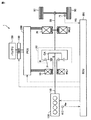
図1は、本実施の形態に係る車両1の全体構成を概略的に示すブロック図である。車両1は、エンジン100と、モータジェネレータ(第1回転電機)10と、モータジェネレータ(第2回転電機)20と、遊星歯車機構30と、駆動輪50と、駆動輪50に接続された出力軸60と、車速センサ71と、バッテリ150と、システムメインリレー(SMR:System Main Relay)160と、電力制御ユニット(PCU:Power Control Unit)200と、電子制御ユニット(ECU:Electronic Control Unit)300とを備える。
<Overall configuration of vehicle>
FIG. 1 is a block diagram schematically showing an overall configuration of a
車両1は、エンジン100とモータジェネレータ20との少なくとも一方の動力を用いて走行するハイブリッド車両である。車両1は、後述する通常走行中において、エンジン100の動力を用いずにモータジェネレータ20の動力を用いて走行する電気自動車走行(以下「EV走行」という)と、エンジン100およびモータジェネレータ20の双方の動力を用いて走行するハイブリッド自動車走行(以下「HV走行」という)との間で走行態様を切り替えることができる。
The
エンジン100は、ガソリンエンジンまたはディーゼルエンジン等の内燃機関である。エンジン100は、ECU300からの制御信号に応じて車両1が走行するための動力を発生する。エンジン100により発生した動力は遊星歯車機構30に出力される。
The
エンジン100にはエンジン回転速度センサ410が設けられている。エンジン回転速度センサ410は、エンジン100の回転速度(エンジン回転速度)Neを検出し、その検出結果を示す信号をECU300に出力する。
The
モータジェネレータ10,20の各々は、三相交流永久磁石型同期モータである。モータジェネレータ10は、エンジン100を始動させる際にはバッテリ150の電力を用いてエンジン100のクランクシャフト110を回転させる。なお、車両1は、補機バッテリ(図示せず)の電力を用いてエンジンをクランキングするためのトルクを発生するスタータは備えていない。
Each of
モータジェネレータ10は、エンジン100の動力を用いて発電することも可能である。モータジェネレータ10によって発電された交流電力は、PCU200により直流電力に変換されてバッテリ150に充電される。また、モータジェネレータ10によって発電された交流電力がモータジェネレータ20に供給される場合もある。
The
モータジェネレータ20のロータは、出力軸60に連結される。モータジェネレータ20は、バッテリ150およびモータジェネレータ10の少なくとも一方から供給される電力を用いて出力軸60を回転させる。また、モータジェネレータ20は、回生制動によって発電することも可能である。モータジェネレータ20によって発電された交流電力は、PCU200により直流電力に変換されてバッテリ150に充電される。
The rotor of
遊星歯車機構30は、エンジン100、モータジェネレータ10および出力軸60を機械的に連結し、エンジン100、モータジェネレータ10および出力軸60の間でトルクを伝達するように構成される。具体的には、遊星歯車機構30は、回転要素として、モータジェネレータ10のロータに連結されるサンギヤSと、出力軸60に連結されるリングギヤRと、エンジン100のクランクシャフト110に連結されるキャリアCAと、サンギヤSとリングギヤRとに噛合するピニオンギヤPとを含む。キャリアCAは、ピニオンギヤPが自転かつ公転できるようにピニオンギヤPを保持する。
The
バッテリ150は、再充電が可能に構成されたリチウムイオン二次電池である。なお、バッテリ150は、ニッケル水素二次電池などの他の二次電池であってもよい。
The
SMR160は、バッテリ150とPCU200との間の電力線に直列に接続されている。SMR160は、ECU300からの制御信号に応じて、バッテリ150とPCU200との導通状態および遮断状態を切り替える。
PCU200は、バッテリ150に蓄えられた直流電力を昇圧し、昇圧された電圧を交流電圧に変換してモータジェネレータ10およびモータジェネレータ20に供給する。また、PCU200は、モータジェネレータ10およびモータジェネレータ20により発電された交流電力を直流電力に変換してバッテリ150に供給する。PCU200の構成については図2にて詳細に説明する。
車速センサ71は、駆動輪50の回転速度を車両1の速度(車速)VSとして検出し、検出結果を示す信号をECU300に出力する。
The
ECU300は、いずれも図示しないが、CPU(Central Processing Unit)と、メモリと、入出力バッファ等とを含んで構成される。ECU300は、各センサおよび機器からの信号、ならびにメモリに格納されたマップおよびプログラムに基づいて、車両1が所望の走行状態となるようにエンジン100の出力(燃料噴射、点火時期、スロットル開度等)およびモータジェネレータ10,20の出力(通電量)を制御する。なお、各種制御については、ソフトウェアによる処理に限られず、専用のハードウェア(電子回路)により処理することも可能である。
Although not shown,
<電気システムおよびECUの構成>
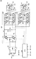
図2は、車両1の電気システムの構成を説明するための回路ブロック図である。車両1の電気システムは、バッテリ150と、SMR160と、PCU200と、モータジェネレータ10,20と、ECU300とを含む。PCU200は、コンバータ210と、コンデンサC2と、インバータ221,222と、電圧センサ230とを含む。
<Configuration of electrical system and ECU>
FIG. 2 is a circuit block diagram for explaining the configuration of the electric system of the
バッテリ150には監視ユニット440が設けられている。監視ユニット440は、バッテリ150の電圧(バッテリ電圧)VB、バッテリ150を流れる電流(バッテリ電流)IB、バッテリ150の温度(バッテリ温度)TBをそれぞれ検出して、それらの検出結果を示す信号をECU300に出力する。
The
コンバータ210は、コンデンサC1と、リアクトルL1と、スイッチング素子Q1(上アーム)およびスイッチング素子Q2(下アーム)と、ダイオードD1,D2とを含む。コンデンサC1は、バッテリ電圧VBを平滑化してコンバータ210に供給する。スイッチング素子Q1,Q2および後述するスイッチング素子Q3〜Q14の各々は、たとえばIGBT(Insulated Gate Bipolar Transistor)である。スイッチング素子Q1,Q2は、電力線PLと電力線NLとの間に互いに直列に接続されている。ダイオードD1,D2は、スイッチング素子Q1,Q2のコレクタ−エミッタ間に逆並列にそれぞれ接続されている。リアクトルL1の一方端は、バッテリ150の高電位側に接続されている。リアクトルL1の他方端は、上アームと下アームとの中間点(スイッチング素子Q1のエミッタとスイッチング素子Q2のコレクタとの接続点)に接続されている。
コンバータ210は、ECU300からの制御信号に応じた上側アームおよび下側アームのスイッチング動作によって、バッテリ150から入力されるバッテリ電圧VBを昇圧して電力線PL,NLに出力する。また、コンバータ210は、ECU300からの制御信号に応じた上側アームおよび下側アームのスイッチング動作によって、インバータ221およびインバータ222の一方または両方から供給される電力線PL,NLの電圧を降圧してバッテリ150に出力する。コンバータ210の動作により、電力線PL,NL間の電圧(以下「システム電圧」ともいう)VHは、バッテリ電圧VB以上の値となる。
コンデンサC2は、電力線PLと電力線NLとの間に接続されている。コンデンサC2は、コンバータ210から供給された直流電圧を平滑化してインバータ221,222に供給する。
Capacitor C2 is connected between power line PL and power line NL. Capacitor C <b> 2 smoothes the DC voltage supplied from
電圧センサ230は、コンデンサC2の両端の電圧、すなわちシステム電圧VHを検出し、その検出結果を示す信号をECU300に出力する。
インバータ221(以下「第1インバータ221」ともいう)は、システム電圧VHが供給されると、ECU300からの制御信号に応じて、直流電圧を交流電圧に変換してモータジェネレータ10を駆動する。第1インバータ221は、U相アーム1Uと、V相アーム1Vと、W相アーム1Wとを含む。各相アームは、電力線PLと電力線NLとの間に互いに並列に接続されている。U相アーム1Uは、互いに直列に接続されたスイッチング素子Q3(上アーム)およびスイッチング素子Q4(下アーム)を有する。V相アーム1Vは、互いに直列に接続されたスイッチング素子Q5(上アーム)およびスイッチング素子Q6(下アーム)を有する。W相アーム1Wは、互いに直列に接続されたスイッチング素子Q7(上アーム)およびスイッチング素子Q8(下アーム)を有する。各スイッチング素子Q3〜Q8のコレクタ−エミッタ間には、ダイオードD3〜D8が逆並列にそれぞれ接続されている。
When system voltage VH is supplied, inverter 221 (hereinafter also referred to as “
インバータ222(以下「第2インバータ222」ともいう)は、各相アーム2U〜2Wと、スイッチング素子Q9〜Q14と、ダイオードD9〜D14とを含む。なお、第2インバータ222の構成は、基本的には第1インバータ221の構成と同等であるため、説明は繰り返さない。
Inverter 222 (hereinafter also referred to as “
モータジェネレータ10には、レゾルバ421および電流センサ241が設けられる。モータジェネレータ20には、レゾルバ422および電流センサ242が設けられる。レゾルバ421は、モータジェネレータ10の回転速度(MG1回転速度Nm1)を検出する。レゾルバ422は、モータジェネレータ20の回転速度(MG2回転速度Nm2)を検出する。電流センサ241は、モータジェネレータ10を流れる電流(モータ電流)IM1を検出する。電流センサ242は、モータジェネレータ20を流れる電流(モータ電流)IM2を検出する。これらのセンサは、検出結果を示す信号をECU300にそれぞれ出力する。
The
ECU300は、各センサからの情報等に基づいて、モータジェネレータ10,20の出力が所望の出力となるようにPCU200(コンバータ210およびインバータ221,222)を制御する。なお、図2に示す例では、ECU300が1つのユニットとして構成されているが、ECU300は、複数のユニットに分割されていてもよい。
<通常走行およびインバータレス走行>
ECU300は、通常モードと退避モードとのどちらかの制御モードで車両1を走行させることができる。
<Normal travel and inverter-less travel>
通常モードは、上述のEV走行とHV走行とを必要に応じて切り替えながら車両1を走行させるモードである。通常モードでは、コンバータ210およびインバータ221,222は、ECU300からの制御信号によって、PWM(Pulse Width Modulation)制御によるスイッチング動作を行なう。以下では、通常モードによる走行を「通常走行」と記載する。
The normal mode is a mode in which the
退避モードは、インバータ221,222のPWM制御によるモータジェネレータ10,20の駆動を正常に行なうことができない異常(以下、このような異常を説明の便宜上「インバータ異常」ともいう)が生じた場合、インバータ221,222のPWM制御を停止しつつエンジン100を駆動状態にすることによって車両1を退避走行させるモードである。なお、インバータ異常には、レゾルバ421,422の故障、電流センサ241,242の故障などが含まれる。以下では、この退避モードによる走行を「インバータレス走行」と記載し、インバータレス走行を行なうための制御を「インバータレス走行制御」と記載する。
In the evacuation mode, when an abnormality in which the
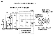
図3は、インバータレス走行中における電気システムの状態の一例を概略的に示す図である。なお、図3においては、インバータ221をゲート遮断状態にする例が示されている。第1インバータ221のスイッチング素子Q3〜Q8がゲート遮断状態とされると、第1インバータ221に含まれるダイオードD3〜D8によって三相全波整流回路が構成される。なお、図3には示されていないが、第2インバータ222も同様にゲート遮断状態とされる。一方、コンバータ210では、ECU300からの制御信号に応答して、スイッチング素子Q1,Q2のPWM制御によるスイッチング動作が継続される。
FIG. 3 is a diagram schematically illustrating an example of the state of the electrical system during inverterless travel. FIG. 3 shows an example in which the
また、インバータレス走行中においては、エンジン100が駆動状態とされ、エンジン100からエンジントルクTeが出力される。このエンジントルクTeによってモータジェネレータ10が力学的(機械的)に回転させられる。モータジェネレータ10は同期モータであるので、モータジェネレータ10のロータには永久磁石12が設けられている。このため、エンジントルクTeによってモータジェネレータ10のロータに設けられた永久磁石12が回転させられることによって、モータジェネレータ10には逆起電圧Vcが生じる。この逆起電圧Vcがシステム電圧VHを超えると、モータジェネレータ10とバッテリ150との間に電流が流れる。この際、モータジェネレータ10には、モータジェネレータ10の回転を妨げる方向に作用する逆起トルクTc(制動トルク)が発生する。
Further, during the inverterless travel, the
以下では、第1インバータ221をゲート遮断状態にして全波整流回路とすることによって発生するモータジェネレータ10の逆起トルクTcを「全波整流トルク」ともいう。
Hereinafter, the counter electromotive torque Tc of the
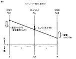
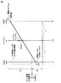
図4は、インバータレス走行中にモータジェネレータ10から全波整流トルクを発生させる場合おけるエンジン100およびモータジェネレータ10,20の制御状態の一例を遊星歯車機構30の共線図上に示す図である。
FIG. 4 is a diagram showing an example of a control state of
遊星歯車機構30の共線図は、遊星歯車機構30のサンギヤS、キャリアCAおよびリングギヤRを縦線で示し、それらの間隔を遊星歯車機構30のギヤ比に対応する間隔とし、さらにそれぞれの縦線の上下方向を回転方向とし、その上下方向での位置を回転数としたものである。遊星歯車機構30は、シングルピニオン型であるため、図4の共線図において、モータジェネレータ10に接続されるサンギヤSは左端に位置する線で表され、エンジン100に接続されるキャリヤCAは中央に位置する線で表され、モータジェネレータ20に接続されるリングギヤRは右端に位置する線で表される。
In the collinear diagram of the
遊星歯車機構30が上記のように構成されることによって、MG1回転速度Nm1(=サンギヤSの回転速度)と、エンジン回転速度Ne(=キャリアCAの回転速度)と、MG2回転速度Nm2(=リングギヤRの回転速度)とは、共線図上において直線で結ばれる関係(いずれか2つの回転速度が決まれば残り1つの回転速度も決まる関係、以下「共線図の関係」ともいう)を有する。
By configuring the
上述のように、インバータレス走行中においては、エンジントルクTeによってモータジェネレータ10が機械的に回転させられることによって、モータジェネレータ10が逆起電圧Vcを発生する。第1インバータ221がゲート遮断状態とされて三相全波整流回路を構成する場合には、逆起電圧Vcがシステム電圧VHを超えるときにモータジェネレータ10とバッテリ150との間に電流が流れ、モータジェネレータ10は逆起トルクTc(全波整流トルク)を発生する。
As described above, during inverterless traveling, the
逆起トルクTcがモータジェネレータ10からサンギヤSに作用することによって、リングギヤRには、逆起トルクTcの反力として、正方向(前進方向)に作用する駆動トルクTepが発生する。この駆動トルクTepによって車両1が退避走行される。
When the counter electromotive torque Tc acts on the sun gear S from the
図5は、ECU300がインバータレス走行制御を行なう際の処理手順を示すフローチャートである。このフローチャートは所定周期で繰り返し実行される。
FIG. 5 is a flowchart showing a processing procedure when
ステップ(以下、ステップを「S」と略す)10にて、ECU300は、上述したインバータ異常が生じているか否かを判定する。インバータ異常が生じていない場合(S10にてNO)、ECU300は、S11にて、制御モードを通常モードに設定して通常走行を行なう。
In step (hereinafter, step is abbreviated as “S”) 10,
インバータ異常が生じている場合(S10にてYES)、ECU300は、S12〜S14にて、制御モードを退避モードに設定してインバータレス走行を行なう。
If an inverter abnormality has occurred (YES in S10),
具体的には、ECU300は、S12にてインバータ221,222のPWM制御を停止する。なお、第2インバータ222においては、PWM制御の停止後、ゲート遮断状態に制御される。一方、第1インバータ221においては、PWM制御の停止後、後述するように、ゲート遮断状態および三相オン状態のいずれかの状態に制御される。なお、第1インバータ221におけるゲート遮断状態および三相オン状態の切替については、後に詳述する。
Specifically,
その後、ECU300は、S13にて、システム電圧VHが目標システム電圧VHtagとなるようにコンバータ210を作動(PWM制御)する。本実施の形態において、目標システム電圧VHtagは、たとえばユーザ要求トルクなどに応じて変動する値とすることができる。なお、目標システム電圧VHtagを予め固定された値とするようにしてもよい。
Thereafter, in S13,
その後、ECU300は、S14にて、エンジン100を駆動状態にする。この際、エンジン回転速度Neが目標エンジン回転速度Netagとなるようにエンジン100のトルクが調整される。本実施の形態において、目標エンジン回転速度Netagは、モータジェネレータ10の逆起電圧Vcがシステム電圧VHを超えるように調整される。そのため、モータジェネレータ10が上述の全波整流トルクを発生し、全波整流トルクの反力として駆動トルクTepが出力される。
Thereafter,
なお、エンジン回転速度Neには、部品保護の観点から、上限回転速度Nemaxが予め定められている。したがって、目標エンジン回転速度Netagは上限回転速度Nemax以下の範囲で調整される。 Note that an upper limit rotational speed Nemax is predetermined for the engine rotational speed Ne from the viewpoint of component protection. Therefore, the target engine rotational speed Netag is adjusted in a range equal to or lower than the upper limit rotational speed Nemax.
<インバータ走行中における全波整流トルクから三相オントルクへの切替>
上述のように、インバータレス走行中において、第1インバータ221をゲート遮断状態にすることによって、モータジェネレータ10から全波整流トルクを発生させ、全波整流トルクの反力が駆動トルクTepとして出力することができる。しかしながら、インバータレス走行中に車速VS(すなわちMG2回転速度Nm2)が高くなると、全波整流トルクが発生しなくなり、駆動トルクTepを出力できなくなるおそれがある。
<Switching from full-wave rectification torque to three-phase on-torque during inverter travel>
As described above, the full-wave rectification torque is generated from the
図6は、インバータレス走行中に高車速となった場合におけるエンジン100およびモータジェネレータ10,20の制御状態の一例を遊星歯車機構30の共線図上に示す図である。
FIG. 6 is a diagram showing an example of a control state of
モータジェネレータ10の全波整流トルクは、上述したように、モータジェネレータ10の逆起電圧Vcがシステム電圧VHを超えた場合に発生する。逆起電圧Vcは、MG1回転速度Nm1と比例関係にあり、MG1回転速度Nm1が低いほど、低い値となる。逆起電圧Vcがシステム電圧VHとなるときのMG1回転速度Nm1を「閾値Nth」としたとき、MG1回転速度Nm1が閾値Nthよりも高い領域R1では逆起電圧Vcがシステム電圧VHよりも高くなりモータジェネレータ10は全波整流トルクを発生可能であるが、MG1回転速度Nm1が閾値Nthよりも低い領域R2では逆起電圧Vcがシステム電圧VHよりも低くなるためモータジェネレータ10は全波整流トルクを発生しない。
As described above, full-wave rectification torque of
車両1においては、車速が高くなる(すなわちMG2回転速度Nm2が高くなる)と、共線図の関係により、MG1回転速度Nm1が低下する。そのため、車速が高い状態においては、たとえエンジン回転速度Neを上限回転速度Nemaxに調整したとしても、MG1回転速度Nm1が閾値Nthよりも低くなってしまい、モータジェネレータ10が全波整流トルクを発生しなくなるおそれがある。
In the
上記の点に鑑み、本実施の形態によるECU300は、インバータ走行中において、MG1回転速度Nm1が閾値Nthよりも低いときには、第1インバータ221をゲート遮断状態ではなく三相オン状態にする。
In view of the above points, the
三相オン状態とは、第1インバータ221の三相のすべての上側アームQ3,Q5,Q7が導通状態に維持され、かつ第1インバータ221の三相のすべての下側Q4,Q6,Q8が非導通状態に維持される状態(以下「上側アーム三相オン状態」ともいう)、または第1インバータ221の三相のすべての下側アームQ4,Q6,Q8が導通状態に維持され、かつ第1インバータ221の三相のすべての上側アームQ3,Q5,Q7が非導通状態に維持される状態(以下「上側アーム三相オン状態」ともいう)である。
In the three-phase ON state, all the three-phase upper arms Q3, Q5, and Q7 of the
第1インバータ221が三相オン状態にされると、モータジェネレータ10と第1インバータ221との間に電流の循環経路が形成されるため、モータジェネレータ10の逆起電圧Vcによってモータジェネレータ10と第1インバータ221との間に電流が流れ、モータジェネレータ10が逆起トルクを発生する。以下、第1インバータ221を三相オン状態にすることによって発生するモータジェネレータ10の逆起トルクTcを「三相オントルク」ともいう。
When the
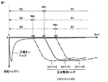
図7は、モータジェネレータ10の逆起トルクTcの特性の一例を示す図である。図7において、横軸はMG1回転速度Nm1を示し、縦軸はモータジェネレータ10の逆起トルクTcを示す。逆起トルクTcには、全波整流トルクと、三相オントルクとが含まれる。
FIG. 7 is a diagram illustrating an example of the characteristics of the counter electromotive torque Tc of the
図7に示すように、全波整流トルクの絶対値は、MG1回転速度Nm1が上述の閾値Nth(逆起電圧Vcがシステム電圧VHとなるときのMG1回転速度Nm1)よりも高い領域R1で0よりも大きい値となり、MG1回転速度Nm1が閾値Nthよりも低い領域R2で0となる特性を有する。そして、閾値Nthは、図7に示すように、システム電圧VHが高いほど、高い値となる。すなわち、システム電圧VHが所定値V2,V1,V3(V2<V1<V3)である場合、閾値Nthは、それぞれ所定値N2,N1,N3(N2<N1<N3)となる。 As shown in FIG. 7, the absolute value of the full-wave rectifying torque is 0 in the region R1 where the MG1 rotational speed Nm1 is higher than the above-described threshold Nth (MG1 rotational speed Nm1 when the back electromotive voltage Vc becomes the system voltage VH). The MG1 rotational speed Nm1 is 0 in the region R2 where the MG1 rotational speed Nm1 is lower than the threshold value Nth. As shown in FIG. 7, the threshold value Nth is higher as the system voltage VH is higher. That is, when the system voltage VH is a predetermined value V2, V1, V3 (V2 <V1 <V3), the threshold value Nth is a predetermined value N2, N1, N3 (N2 <N1 <N3), respectively.
これに対し、三相オントルクの絶対値は、図7に示すように、MG1回転速度Nm1が高い領域R1(全波整流トルクが0よりも大きくなる領域)においては非常に低い値となるが、MG1回転速度Nm1が低い領域R2(全波整流トルクが0となる領域)においては0よりも大きい値となり、特にMG1回転速度Nm1が0に近い値で非常に高いピーク値となる特性を有する。 On the other hand, as shown in FIG. 7, the absolute value of the three-phase on-torque is a very low value in the region R1 where the MG1 rotational speed Nm1 is high (the region where the full-wave rectified torque is greater than 0). In the region R2 where the MG1 rotational speed Nm1 is low (region where the full-wave rectifying torque is 0), the value is larger than 0, and in particular, the MG1 rotational speed Nm1 has a characteristic of having a very high peak value near 0.
なお、三相オントルクの大きさ(絶対値)は、システム電圧VHによっては変動しない。すなわち、三相オントルクは、モータジェネレータ10の逆起電圧Vcに応じた電流がモータジェネレータ10と第1インバータ221との間に流れることによって発生する。そのため、三相オントルクの大きさは、システム電圧VHの影響を受けない。
Note that the magnitude (absolute value) of the three-phase on-torque does not vary depending on the system voltage VH. That is, the three-phase on-torque is generated when a current corresponding to the counter electromotive voltage Vc of the
図7に示すような全波整流トルクおよび三相オントルクの特性に鑑み、ECU300は、システム電圧VHに応じて閾値Nthを設定し、MG1回転速度Nm1が閾値Nthよりも高いか否かを判定する。そして、MG1回転速度Nm1が閾値Nthよりも高い場合には、ECU300は、第1インバータ221をゲート遮断状態にしてモータジェネレータ10から全波整流トルクを発生させる。一方、MG1回転速度Nm1が閾値Nthよりも低い場合には、ECU300は、第1インバータ221を三相オン状態にしてモータジェネレータ10から三相オントルクを発生させる。これにより、インバータレス走行中にMG1回転速度Nm1が閾値Nthよりも低下したとしても駆動トルクTepを確保することができる。
In view of the characteristics of full-wave rectification torque and three-phase on-torque as shown in FIG. 7,
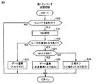
図8は、インバータレス走行中に第1インバータ221の状態をゲート遮断状態または三相オン状態に切り替える際にECU300が行なう処理手順を示すフローチャートである。
FIG. 8 is a flowchart illustrating a processing procedure performed by the
S20にて、ECU300は、インバータレス走行中であるか否かを判定する。インバータレス走行中でない場合(S20にてNO)、ECU300は処理を終了する。
In S20,
インバータレス走行中である場合(S20にてYES)、ECU300は、システム電圧VHに基づいて上述の閾値Nthを算出する。ECU300は、システム電圧VHが高いほど、閾値Nthを大きい値に設定する(上述の図7参照)。
When the inverter is running (YES in S20),
その後、ECU100は、S22にて、ユーザが駆動トルクを要求しているか否かを判定する。たとえば、ECU300は、車両1のシフトレンジがD(ドライブ)レンジまたはB(ブレーキレンジ)などの前進レンジであって、アクセルペダル操作量が所定値を超えている場合に、ユーザが駆動トルクを要求していると判定する。
Thereafter,
ユーザが駆動トルクを要求していない場合(S22にてNO)、ECU300は、S23にて、第1インバータ221をゲート遮断状態にする。この際、ECU300は、MG1回転速度Nm1が閾値Nth未満となるようにエンジン回転速度Neを調整する。これにより、エンジン100を駆動状態に維持したまま、全波整流トルクが0となり、駆動トルクTepの出力が抑制される。
If the user has not requested drive torque (NO in S22),
ユーザが駆動トルクを要求している場合(S22にてYES)、ECU300は、S24にて、MG1回転速度Nm1が閾値Nthよりも高いか否かを判定する。
If the user is requesting drive torque (YES in S22),
MG1回転速度Nm1が閾値Nthよりも高い場合(S24にてYES)、ECU300は、S25にて、第1インバータ221をゲート遮断状態にする。これにより、モータジェネレータ10から全波整流トルクが発生し、全波整流トルクの反力が駆動トルクTepとして出力される。
When MG1 rotation speed Nm1 is higher than threshold value Nth (YES in S24),
一方、MG1回転速度Nm1が閾値Nthよりも低い場合(S24にてNO)、ECU300は、S26にて、第1インバータ221を三相オン状態にする。すなわち、第1インバータ221がゲート遮断状態である場合には、第1インバータ221の状態をゲート遮断状態から三相オン状態に切り替える。これにより、モータジェネレータ10から三相オントルクが発生し、三相オントルクの反力が駆動トルクTepとして出力される。
On the other hand, when MG1 rotation speed Nm1 is lower than threshold value Nth (NO in S24),
以上のように、本実施の形態によるECU300は、インバータレス走行中において、MG1回転速度Nm1が閾値Nthよりも低いときは、ECU300は、全波整流トルクが発生しなくなるおそれがあることに鑑み、第1インバータ221をゲート遮断状態ではなく三相オン状態にする。これにより、モータジェネレータ10から三相オントルクを発生させ、三相オントルクの反力を駆動トルクTepとして出力することができる。その結果、インバータレス走行中において、車速が高くなってMG1回転速度Nm1が閾値Nthよりも低下しても駆動トルクを確保することができる。
As described above,
一方、インバータレス走行中において、MG1回転速度Nm1が閾値Nthよりも高いときは、ECU100は、三相オントルクが非常に低い値となる一方、全波整流トルクを発生可能であることに鑑み、第1インバータ221をゲート遮断状態にする。これにより、モータジェネレータ10から全波整流トルクを発生させ、全波整流トルクの反力を駆動トルクTepとして出力することができる。
On the other hand, when the MG1 rotational speed Nm1 is higher than the threshold value Nth during inverter-less travel, the
さらに、ECU300は、システム電圧VHが高くなるほど全波整流トルクを発生可能なMG1回転速度Nm1の下限値が高くなることに鑑み、システム電圧VHが高いほど閾値Nthを大きい値に設定する。これにより、第1インバータ221がゲート遮断状態から三相オン状態に切り替えられるMG1回転速度Nm1(閾値Nth)を、システム電圧VHに応じて適切に設定することができる。
Further, in view of the fact that the lower limit value of MG1 rotational speed Nm1 at which full-wave rectification torque can be generated increases as system voltage VH increases,
なお、上述の実施の形態においては、遊星歯車機構30のサンギヤS、キャリアCAおよびリングギヤRが、モータジェネレータ10、エンジン100および出力軸60にそれぞれ接続される場合を示した。しかしながら、少なくとも遊星歯車機構30のキャリアCA(共線図において中央に位置する線で表わされる回転要素)がエンジン100に接続されていれば、遊星歯車機構30は上述の構成に限定されない。たとえば、遊星歯車機構30のキャリアCAがエンジン100に接続され、サンギヤSが出力軸60に接続され、リングギヤRがモータジェネレータ10に接続されるようにしてもよい。
In the above-described embodiment, the sun gear S, the carrier CA, and the ring gear R of the
また、上述の実施の形態においては、シングルピニオン型の遊星歯車機構30を使用する場合を示した。しかしながら、シングルピニオン型の遊星歯車機構30に代えて、ダブルピニオン型の遊星歯車機構を採用することもできる。ダブルピニオン型の遊星歯車機構においては、共線図において中央に位置する線で表わされる回転要素がキャリアではなくリングギヤとなる。そのため、ダブルピニオン型の遊星歯車機構を採用する場合には、エンジン100をリングギヤに接続し、モータジェネレータ10および出力軸60の一方をサンギヤに接続し、他方をキャリヤに接続するようにすればよい。
Moreover, in the above-mentioned embodiment, the case where the single pinion type
今回開示された実施の形態はすべての点で例示であって制限的なものではないと考えられるべきである。本発明の範囲は上記した説明ではなくて特許請求の範囲によって示され、特許請求の範囲と均等の意味および範囲内でのすべての変更が含まれることが意図される。 The embodiment disclosed this time should be considered as illustrative in all points and not restrictive. The scope of the present invention is defined by the terms of the claims, rather than the description above, and is intended to include any modifications within the scope and meaning equivalent to the terms of the claims.
1 車両、10,20 モータジェネレータ、12 永久磁石、30 遊星歯車機構、50 駆動輪、60 出力軸、71 車速センサ、100 エンジン、110 クランクシャフト、160 SMR、150 バッテリ、200 PCU、210 コンバータ、221 第1インバータ、222 第2インバータ、230 電圧センサ、241,242 電流センサ、300 ECU、410 エンジン回転速度センサ、421,422 レゾルバ、440 監視ユニット。
DESCRIPTION OF
Claims (2)
エンジンと、
永久磁石が装着されたロータを有する第1回転電機と、
駆動輪に接続された出力軸と、
前記エンジンに接続される回転要素と、前記第1回転電機に接続される回転要素と、前記出力軸に接続される回転要素とを含み、前記エンジン、前記第1回転電機および前記出力軸を機械的に連結する遊星歯車機構とを備え、
前記エンジンに接続される回転要素は、前記遊星歯車機構の共線図において中央に位置する線で表わされる回転要素であり、
前記ハイブリッド車両は、さらに、
前記出力軸に接続された第2回転電機と、
バッテリと、
前記バッテリと電力線との間に電気的に接続されたコンバータと、
前記電力線および前記第1回転電機の間に電気的に接続され、各々が上側アームおよび下側アームを有する三相の駆動アームを有する第1インバータと、
前記電力線および前記第2回転電機の間に電気的に接続された第2インバータと、
前記第1インバータおよび前記第2インバータのPWM制御を停止しつつ前記エンジンを駆動状態にするインバータレス走行制御を実行可能な制御装置とを備え、
前記制御装置は、前記インバータレス走行制御の実行中にユーザが駆動トルクを要求している場合、前記第1回転電機の回転速度が閾値よりも高いときは前記第1インバータをゲート遮断状態にし、前記第1回転電機の回転速度が前記閾値よりも低いときは前記第1インバータを三相オン状態にし、
前記三相オン状態は、前記第1インバータの前記三相のすべての前記上側アームが導通状態に維持されるとともに前記第1インバータの前記三相のすべての前記下側アームが非導通状態に維持される状態、または前記第1インバータの前記三相のすべての前記下側アームが導通状態に維持されるとともに前記第1インバータの前記三相のすべての前記上側アームが非導通状態に維持される状態であり、
前記ゲート遮断状態は、前記第1インバータの前記三相のすべての前記上側アームおよび前記第1インバータの前記三相のすべての前記下側アームが非導通状態に維持される状態である、ハイブリッド車両。 A hybrid vehicle,
Engine,
A first rotating electric machine having a rotor on which a permanent magnet is mounted;
An output shaft connected to the drive wheels;
A rotating element connected to the engine, a rotating element connected to the first rotating electrical machine, and a rotating element connected to the output shaft, the engine, the first rotating electrical machine and the output shaft being a machine A planetary gear mechanism that is connected to the vehicle,
The rotating element connected to the engine is a rotating element represented by a line located in the center in the alignment chart of the planetary gear mechanism,
The hybrid vehicle further includes:
A second rotating electrical machine connected to the output shaft;
Battery,
A converter electrically connected between the battery and a power line;
A first inverter electrically connected between the power line and the first rotating electrical machine, each having a three-phase drive arm having an upper arm and a lower arm;
A second inverter electrically connected between the power line and the second rotating electrical machine;
A control device capable of executing inverter-less running control for bringing the engine into a driving state while stopping PWM control of the first inverter and the second inverter;
The control device, when the user is requesting a driving torque during the execution of the inverterless travel control, when the rotational speed of the first rotating electrical machine is higher than a threshold, the first inverter is in a gate cutoff state, When the rotation speed of the first rotating electrical machine is lower than the threshold value, the first inverter is turned on in a three-phase state,
In the three-phase ON state, all the upper arms of the three phases of the first inverter are maintained in a conductive state and all the lower arms of the three phases of the first inverter are maintained in a nonconductive state. Or all the lower arms of the three phases of the first inverter are maintained in a conductive state and all the upper arms of the three phases of the first inverter are maintained in a nonconductive state. State
The gate cutoff state is a state in which all the three-phase upper arms of the first inverter and all the three-phase lower arms of the first inverter are maintained in a non-conductive state. .
Priority Applications (1)
| Application Number | Priority Date | Filing Date | Title |
|---|---|---|---|
| JP2016008129A JP2017128193A (en) | 2016-01-19 | 2016-01-19 | Hybrid vehicle |
Applications Claiming Priority (1)
| Application Number | Priority Date | Filing Date | Title |
|---|---|---|---|
| JP2016008129A JP2017128193A (en) | 2016-01-19 | 2016-01-19 | Hybrid vehicle |
Publications (1)
| Publication Number | Publication Date |
|---|---|
| JP2017128193A true JP2017128193A (en) | 2017-07-27 |
Family
ID=59394347
Family Applications (1)
| Application Number | Title | Priority Date | Filing Date |
|---|---|---|---|
| JP2016008129A Pending JP2017128193A (en) | 2016-01-19 | 2016-01-19 | Hybrid vehicle |
Country Status (1)
| Country | Link |
|---|---|
| JP (1) | JP2017128193A (en) |
Cited By (1)
| Publication number | Priority date | Publication date | Assignee | Title |
|---|---|---|---|---|
| JP2018184060A (en) * | 2017-04-25 | 2018-11-22 | トヨタ自動車株式会社 | Hybrid vehicle |
-
2016
- 2016-01-19 JP JP2016008129A patent/JP2017128193A/en active Pending
Cited By (1)
| Publication number | Priority date | Publication date | Assignee | Title |
|---|---|---|---|---|
| JP2018184060A (en) * | 2017-04-25 | 2018-11-22 | トヨタ自動車株式会社 | Hybrid vehicle |
Similar Documents
| Publication | Publication Date | Title |
|---|---|---|
| CN107031378B (en) | Hybrid vehicle | |
| JP6426584B2 (en) | Hybrid vehicle | |
| JP6365502B2 (en) | Hybrid vehicle | |
| JP6252574B2 (en) | Hybrid vehicle | |
| JP6439726B2 (en) | vehicle | |
| JP6354723B2 (en) | Hybrid vehicle | |
| CN107199873B (en) | hybrid vehicle | |
| JP6743740B2 (en) | vehicle | |
| JP6330834B2 (en) | Hybrid vehicle | |
| JP6264354B2 (en) | Hybrid vehicle | |
| JP6344345B2 (en) | Hybrid vehicle | |
| JP2018176970A (en) | Hybrid vehicle and control method thereof | |
| JP2010178556A (en) | Motor drive system | |
| JP6398924B2 (en) | Hybrid vehicle | |
| JP2017056790A (en) | Hybrid vehicle | |
| JP2017128193A (en) | Hybrid vehicle | |
| JP2017061186A (en) | Hybrid vehicle | |
| JP2017039404A (en) | Hybrid vehicle | |
| JP2017047846A (en) | Hybrid vehicle | |
| JP2017114209A (en) | Hybrid vehicle | |
| JP2017081241A (en) | Hybrid vehicle | |
| JP6455379B2 (en) | Hybrid vehicle | |
| JP2017056851A (en) | Hybrid vehicle | |
| JP2017114222A (en) | Hybrid vehicle | |
| JP2017061211A (en) | Hybrid vehicle |