JP2017128252A - Pneumatic tire, tire deterioration-determining method and method for determining tire reclamation possibility - Google Patents
Pneumatic tire, tire deterioration-determining method and method for determining tire reclamation possibility Download PDFInfo
- Publication number
- JP2017128252A JP2017128252A JP2016009630A JP2016009630A JP2017128252A JP 2017128252 A JP2017128252 A JP 2017128252A JP 2016009630 A JP2016009630 A JP 2016009630A JP 2016009630 A JP2016009630 A JP 2016009630A JP 2017128252 A JP2017128252 A JP 2017128252A
- Authority
- JP
- Japan
- Prior art keywords
- tire
- deterioration
- tool
- determining
- pneumatic
- Prior art date
- Legal status (The legal status is an assumption and is not a legal conclusion. Google has not performed a legal analysis and makes no representation as to the accuracy of the status listed.)
- Granted
Links
Images


Landscapes
- Tires In General (AREA)
Abstract
【課題】 タイヤの劣化度合いを簡単に判定することを可能にした空気入りタイヤ、タイヤ劣化判定方法及びタイヤ更生可否判定方法を提供する。【解決手段】 本発明の空気入りタイヤは、ゴム組成物の成形体11からなるタイヤ劣化判定具10を備え、該タイヤ劣化判定具10は初期歪が与えられた状態でタイヤ内面Sに装着される。タイヤ使用開始後の任意の時点でタイヤ劣化判定具10の破断状態を確認し、その破断状態に基づいて空気入りタイヤの劣化度合いを判定する。また、タイヤ更生時にタイヤ劣化判定具10の破断状態を確認し、その破断状態に基づいて空気入りタイヤの更生可否を判定する。【選択図】図1PROBLEM TO BE SOLVED: To provide a pneumatic tire, a tire deterioration judging method and a tire rehabilitation judging method capable of easily judging the degree of tire degradation. A pneumatic tire according to the present invention includes a tire deterioration determining tool 10 made of a molded body 11 of a rubber composition, and the tire deterioration determining tool 10 is attached to a tire inner surface S in a state where an initial strain is applied. The The rupture state of the tire deterioration determination tool 10 is confirmed at an arbitrary time after the start of tire use, and the degree of deterioration of the pneumatic tire is determined based on the rupture state. In addition, the tire degradation determination tool 10 is checked for a ruptured state at the time of tire retreading, and whether or not a pneumatic tire can be retreaded is determined based on the ruptured state. [Selection] Figure 1
Description
本発明は、タイヤ劣化判定具を備えた空気入りタイヤ及びその関連技術に関し、更に詳しくは、タイヤの劣化度合いを簡単に判定することを可能にした空気入りタイヤ、タイヤ劣化判定方法及びタイヤ更生可否判定方法に関する。 The present invention relates to a pneumatic tire provided with a tire deterioration determination tool and related technology, and more specifically, a pneumatic tire, a tire deterioration determination method, and tire regeneration possibility that can easily determine the degree of deterioration of the tire. It relates to a determination method.
近年、資源の有効活用及び省エネルギーの観点から、空気入りタイヤのトレッド部が摩耗して使用不能の状態になった後、その空気入りタイヤを再生して得られる更生タイヤが普及している。特に、トラックやバスに使用される重荷重用空気入りタイヤについては、更生タイヤが広く使用されている。 In recent years, from the viewpoint of effective utilization of resources and energy saving, retread tires obtained by regenerating a pneumatic tire after the tread portion of the pneumatic tire is worn and becomes unusable have become widespread. In particular, retreaded tires are widely used for heavy duty pneumatic tires used in trucks and buses.
使用済みの空気入りタイヤを更生する場合、トレッドゴムが研削された台タイヤを作製し、その台タイヤに対して新たなトレッドゴムを被覆する。そのような更生作業を行うにあたって、台タイヤの残存耐久性を確認するために、シェアログラフィ検査により内部セパレーションの有無を確認したり、外観検査により外傷の有無を確認したりすることが行われている。しかしながら、このような検査は多大な時間を要すると共に作業が煩雑である。 When a used pneumatic tire is rehabilitated, a base tire in which the tread rubber is ground is produced, and the base tire is covered with a new tread rubber. When performing such rehabilitation work, in order to confirm the remaining durability of the base tire, the presence of internal separation is confirmed by shearography inspection, and the presence or absence of trauma is confirmed by appearance inspection. ing. However, such an inspection requires a lot of time and is complicated.
また、硫黄架橋可能なジエン系ゴム組成物からなる芯体ゴムがタイヤのインナーライナー層と同等又はそれ以上の酸素透過係数を有するカバーゴムで被覆されたタイヤ劣化判定具をタイヤ内面に設置し、そのタイヤ劣化判定具の屈曲試験の結果に基づいて空気入りタイヤの劣化度合いを判定することが提案されている(例えば、特許文献1参照)。しかしながら、この場合も、タイヤ劣化判定具をタイヤ内面から取り外し、タイヤ劣化判定具に対して屈曲試験を行う必要があるため、空気入りタイヤの劣化度合いを即座に判断することができない。 In addition, a tire deterioration determining tool in which a core rubber made of a sulfur-crosslinkable diene rubber composition is covered with a cover rubber having an oxygen permeability coefficient equal to or higher than that of the inner liner layer of the tire is installed on the inner surface of the tire, It has been proposed to determine the degree of deterioration of a pneumatic tire based on the result of the bending test of the tire deterioration determination tool (see, for example, Patent Document 1). However, in this case as well, it is necessary to remove the tire deterioration determination tool from the tire inner surface and perform a bending test on the tire deterioration determination tool, so that the degree of deterioration of the pneumatic tire cannot be immediately determined.
本発明の目的は、タイヤの劣化度合いを簡単に判定することを可能にした空気入りタイヤ、タイヤ劣化判定方法及びタイヤ更生可否判定方法を提供することにある。 An object of the present invention is to provide a pneumatic tire, a tire deterioration determination method, and a tire rehabilitation determination method that can easily determine the degree of deterioration of a tire.
上記目的を達成するための本発明の空気入りタイヤは、ゴム組成物の成形体からなるタイヤ劣化判定具を備え、該タイヤ劣化判定具は初期歪が与えられた状態でタイヤ内面に装着されていることを特徴とするものである。 In order to achieve the above object, a pneumatic tire according to the present invention includes a tire deterioration determination tool made of a molded rubber composition, and the tire deterioration determination tool is attached to the tire inner surface in a state where an initial strain is applied. It is characterized by being.
また、上記目的を達成するための本発明のタイヤ劣化判定方法は、上述した空気入りタイヤの劣化度合いを判定する方法であって、タイヤ使用開始後の任意の時点で前記タイヤ劣化判定具の破断状態を確認し、その破断状態に基づいて前記空気入りタイヤの劣化度合いを判定することを特徴とするものである。 Further, the tire deterioration determination method of the present invention for achieving the above object is a method for determining the degree of deterioration of the pneumatic tire described above, wherein the tire deterioration determination tool is broken at an arbitrary time after the start of tire use. The state is confirmed, and the degree of deterioration of the pneumatic tire is determined based on the fractured state.
更に、上記目的を達成するための本発明のタイヤ更生可否判定方法は、上述した空気入りタイヤの更生可否を判定する方法であって、タイヤ更生時に前記タイヤ劣化判定具の破断状態を確認し、その破断状態に基づいて前記空気入りタイヤの更生可否を判定することを特徴とするものである。 Furthermore, the tire rehabilitation determination method of the present invention for achieving the above object is a method for determining the renewal possibility of the pneumatic tire described above, and confirming the rupture state of the tire deterioration determination tool at the time of tire rehabilitation, Whether or not the pneumatic tire is rehabilitated is determined based on the fractured state.
本発明では、空気入りタイヤがゴム組成物の成形体からなるタイヤ劣化判定具を備え、そのタイヤ劣化判定具は初期歪が与えられた状態でタイヤ内面に装着されているので、酸化劣化に伴ってタイヤ劣化判定具の破断伸びが低下し、それが予め設定された初期歪を下回ると、タイヤ劣化判定具に破断を生じることになる。そのため、タイヤ劣化判定具の破断状態に基づいて空気入りタイヤの劣化度合いを簡単に判定することができる。 In the present invention, the pneumatic tire is provided with a tire deterioration determination tool made of a molded rubber composition, and the tire deterioration determination tool is attached to the tire inner surface with an initial strain applied. If the elongation at break of the tire deterioration determining tool decreases and falls below a preset initial strain, the tire deterioration determining tool will break. Therefore, it is possible to easily determine the degree of deterioration of the pneumatic tire based on the fracture state of the tire deterioration determining tool.
本発明の空気入りタイヤにおいて、タイヤ劣化判定具がシート状の成形体からなり、該タイヤ劣化判定具は初期歪が与えられた状態で粘着層を介してタイヤ内面に装着されていることが好ましい。これにより、タイヤ劣化判定具に対して所望の初期歪を与えた状態で該タイヤ劣化判定具をタイヤ内面に保持することができる。 In the pneumatic tire of the present invention, the tire deterioration determination tool is preferably a sheet-like molded body, and the tire deterioration determination tool is preferably attached to the tire inner surface via an adhesive layer in a state where an initial strain is applied. . Thereby, the tire deterioration determination tool can be held on the tire inner surface in a state where a desired initial strain is applied to the tire deterioration determination tool.
或いは、タイヤ劣化判定具がリング状の成形体からなり、タイヤ内面に突起が形成されており、タイヤ劣化判定具は突起の周囲に嵌め合わされて初期歪が与えられた状態でタイヤ内面に装着されていることが好ましい。これにより、タイヤ劣化判定具に対して所望の初期歪を与えた状態で該タイヤ劣化判定具をタイヤ内面に保持することができる。 Alternatively, the tire deterioration determination tool is made of a ring-shaped molded body, and a protrusion is formed on the inner surface of the tire. The tire deterioration determination tool is fitted around the protrusion and attached to the tire inner surface in an initial strain state. It is preferable. Thereby, the tire deterioration determination tool can be held on the tire inner surface in a state where a desired initial strain is applied to the tire deterioration determination tool.
本発明の空気入りタイヤにおいて、タイヤ劣化判定具はトレッド幅の中央側75%の領域又はタイヤ断面高さの25%以下の領域においてタイヤ内面に装着されていることが好ましい。これら領域ではタイヤ走行時にタイヤ内面が変形し難いため、タイヤ劣化判定具に掛かる歪を低減し、酸素による劣化度合いを精度良く判定することができる。 In the pneumatic tire of the present invention, it is preferable that the tire deterioration determination tool is mounted on the inner surface of the tire in a region of 75% of the center side of the tread width or a region of 25% or less of the tire cross-section height. In these regions, since the tire inner surface is difficult to deform during running of the tire, the strain applied to the tire deterioration determination tool can be reduced, and the degree of deterioration due to oxygen can be accurately determined.
本発明の空気入りタイヤにおいて、タイヤ劣化判定具を構成する成形体がタイヤ内面とは異なる色に着色された着色部を有し、該着色部が初期歪の付与方向に沿って延在することが好ましい。タイヤ劣化判定具の破断状態を確認するにあたって、タイヤ劣化判定具の色とタイヤ内面の色とが同じであると破断状態の判断が難しいが、成形体に着色部を設けることにより、破断状態を容易に判断することができる。 In the pneumatic tire of the present invention, the molded body constituting the tire deterioration determination tool has a colored portion colored in a color different from the inner surface of the tire, and the colored portion extends along the direction in which the initial strain is applied. Is preferred. When confirming the rupture state of the tire deterioration determination tool, it is difficult to determine the rupture state if the color of the tire deterioration determination tool and the color of the tire inner surface are the same. It can be easily judged.
本発明の空気入りタイヤにおいて、タイヤ内面に複数個のタイヤ劣化判定具が装着されており、これらタイヤ劣化判定具に与えられた初期歪の値が互いに異なることが好ましい。このように初期歪の値が互いに異なる複数個のタイヤ劣化判定具を設置することにより、空気入りタイヤの劣化度合いを精密に判定することができる。 In the pneumatic tire of the present invention, it is preferable that a plurality of tire deterioration determination tools are mounted on the tire inner surface, and the initial strain values given to these tire deterioration determination tools are different from each other. As described above, by installing a plurality of tire deterioration determining tools having different initial strain values, it is possible to accurately determine the degree of deterioration of the pneumatic tire.
更に、本発明のタイヤ劣化判定方法によれば、タイヤ使用開始後の任意の時点でタイヤ劣化判定具の破断状態を確認することにより、タイヤ劣化判定具の破断状態に基づいて空気入りタイヤの劣化度合いを簡単に判定することができる。 Furthermore, according to the tire deterioration determination method of the present invention, the deterioration of the pneumatic tire is determined based on the rupture state of the tire deterioration determination tool by checking the rupture state of the tire deterioration determination tool at an arbitrary time after the start of tire use. The degree can be easily determined.
更に、本発明のタイヤ更生可否判定方法によれば、タイヤ更生時にタイヤ劣化判定具の破断状態を確認することにより、タイヤ劣化判定具の破断状態に基づいて空気入りタイヤの更生可否を簡単に判定することができる。 Furthermore, according to the tire rehabilitation determination method of the present invention, it is possible to easily determine whether a pneumatic tire is rehabilitated based on the rupture state of the tire deterioration determination tool by checking the rupture state of the tire deterioration determination tool at the time of tire regeneration. can do.
以下、本発明の構成について添付の図面を参照しながら詳細に説明する。図1は本発明の実施形態からなる重荷重用の空気入りタイヤを示し、図2及び図3は本発明に係るタイヤ劣化判定具を示すものである。 Hereinafter, the configuration of the present invention will be described in detail with reference to the accompanying drawings. FIG. 1 shows a heavy-duty pneumatic tire according to an embodiment of the present invention, and FIGS. 2 and 3 show a tire deterioration determining tool according to the present invention.
図1に示すように、本実施形態の空気入りタイヤは、タイヤ周方向に延在して環状をなすトレッド部1と、該トレッド部1の両側に配置された一対のサイドウォール部2,2と、これらサイドウォール部2のタイヤ径方向内側に配置された一対のビード部3,3とを備えている。
As shown in FIG. 1, the pneumatic tire of the present embodiment includes a tread portion 1 that extends in the tire circumferential direction and has an annular shape, and a pair of
一対のビード部3,3間にはカーカス層4が装架されている。このカーカス層4は、タイヤ径方向に延びる複数本の補強コードを含み、各ビード部3に配置されたビードコア5の廻りにタイヤ内側から外側へ折り返されている。ビードコア5の外周上には断面三角形状のゴム組成物からなるビードフィラー6が配置されている。
A carcass layer 4 is mounted between the pair of
一方、トレッド部1におけるカーカス層4の外周側には複数層のベルト層7が埋設されている。これらベルト層7はタイヤ周方向に対して傾斜する複数本の補強コードを含み、かつ層間で補強コードが互いに交差するように配置されている。ベルト層7において、補強コードのタイヤ周方向に対する傾斜角度は例えば10°〜60°の範囲に設定されている。ベルト層7の補強コードとしては、スチールコードが好ましく使用される。
On the other hand, a plurality of
上記空気入りタイヤにおいて、タイヤ気室に面するタイヤ内面Sにはタイヤ劣化判定具10が装着されている。図2に示すように、タイヤ劣化判定具10はシート状であって直方体をなすゴム組成物の成形体11から構成されている。成形体11を構成するゴム組成物としては、例えば、硫黄架橋可能なジエン系ゴム組成物を使用することができる。ジエン系ゴムとしては、天然ゴム(NR)、イソプレンゴム(IR)、エポキシ化天然ゴム、スチレンブタジエンゴム(SBR)、ブタジエンゴム(BR)、ニトリルゴム(NBR)、水素化NBR、水素化SBR等を挙げることができる。但し、タイヤ劣化判定具10の成形体11に使用されるゴムは上記ジエン系ゴムに限定されるものではなく、そのゴムには硫黄、加硫促進剤、老化防止剤、カーボンブラック等の充填剤、オイル等の軟化剤、樹脂、ワックス、コバルト塩等の金属塩、ステアリン酸、亜鉛華等の添加物を適宜配合することができる。特に、タイヤの酸化劣化を判定するにあたって、酸化劣化を生じ易い天然ゴム系のゴム組成物が好ましく、硫黄、更には金属塩を含有するものが好ましい。
In the pneumatic tire, a tire
タイヤ劣化判定具10は、図2に示すように、初期歪が与えられた状態でシート状の粘着層12を介してタイヤ内面Sに対して着脱自在に貼着されている。より具体的には、図3に示すように、タイヤ劣化判定具10の成形体11は貼着前の寸法が貼着後の寸法よりも小さくなっており、その成形体11が一軸方向又は二軸方向に引っ張られた状態で粘着層12を介してタイヤ内面Sに貼り付けられている。これにより、タイヤ劣化判定具10に対して所望の初期歪を与えた状態で該タイヤ劣化判定具10をタイヤ内面Sに保持することができる。粘着層12としては、両面テープや粘着剤等を使用することができる。なお、粘着層12自体が伸縮性を有する場合には、成形体11と粘着層12とが一体化された状態でタイヤ劣化判定具10に対して初期歪を与えても良い。初期歪としては、5%以上、好ましくは10%〜400%の引張り歪を与えることが好ましい。また、歪の形態は一軸方向又は二軸方向の引っ張り歪のほか、捩り歪であっても良い。
As shown in FIG. 2, the tire
上述した空気入りタイヤは、ゴム組成物の成形体11からなるタイヤ劣化判定具10を備え、そのタイヤ劣化判定具10は初期歪が与えられた状態でタイヤ内面Sに装着されているので、酸化劣化に伴ってタイヤ劣化判定具10の破断伸びが低下し、それが予め設定された初期歪を下回ると、タイヤ劣化判定具10に破断を生じることになる。即ち、図4に示すように、タイヤ劣化判定具10破断伸びは使用期間が長くなるに連れて徐々に低下するが、その破断伸びが予め設定された初期歪Aを下回ると、タイヤ劣化判定具10が破断する。そのため、タイヤ劣化判定具10の破断状態に基づいて空気入りタイヤの劣化度合いを簡単に判定することができる。
The pneumatic tire described above includes a tire
上記空気入りタイヤにおいて、タイヤ劣化判定具10はトレッド幅TWの中央側75%に相当する領域X1又はタイヤ断面高さSHの25%以下となる領域X2の範囲内でタイヤ内面Sに装着されているのが良い。これら領域X1,X2ではタイヤ走行時にタイヤ内面Sが変形し難いため、タイヤ劣化判定具10に掛かる歪を低減し、酸素による劣化度合いを精度良く判定することができる。タイヤ劣化判定具10の配置位置が領域X1,X2から外れると、走行時にタイヤ劣化判定具10に対して歪が繰り返し与えられることに起因してタイヤ劣化判定具10に物性変化が起こり、劣化度合いを正確に判断することが困難になる。
In the pneumatic tire, the tire
図5(a),(b)は本発明に係るタイヤ劣化判定具の他の変形例を示すものである。図5(a)に示すように、タイヤ劣化判定具10を構成する成形体11はタイヤ内面Sとは異なる色に着色された着色部13を有しており、その着色部11aは初期歪の付与方向に沿って延在している。着色部13の色としては、例えば、黄色、白色、水色のような黒色以外の色を選択することができる。また、着色部13は着色されたゴム層であっても良く、或いは、塗装により形成された塗膜であっても良い。このような着色部13を設けた場合、図5(b)に示すように、タイヤ劣化判定具10の劣化に伴って初期歪の付与方向とは交差する方向に沿って破断が生じたとき、その破断状態を着色部13に基づいて容易に判別することができる。タイヤ劣化判定具10の破断状態を確認するにあたって、タイヤ劣化判定具10の色とタイヤ内面Sの色とが同じであると破断状態の判断が難しいが、成形体11に着色部13を設けることにより、破断状態を容易に判断することができる。
5 (a) and 5 (b) show another modification of the tire deterioration determining tool according to the present invention. As shown in FIG. 5 (a), the molded
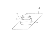
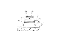
図6及び図7は本発明に係るタイヤ劣化判定具の更に他の変形例を示すものである。図6において、タイヤ劣化判定具10はリング状の成形体11から構成されており、タイヤ内面Sには突起14が形成されている。突起14の形状は円錐状や円柱状であると良い。そして、タイヤ劣化判定具10は突起14の周囲に嵌め合わされて初期歪が与えられた状態でタイヤ内面Sに装着されている。より具体的には、図7に示すように、タイヤ劣化判定具10の成形体11は貼着前の寸法が貼着後の寸法よりも小さくなっており、その成形体11が引っ張られた状態で突起14の周囲に嵌め合わされている。突起14の外周面には環状の溝15が形成されており、この溝15内に成形体11が嵌まり込むようになっている。これにより、タイヤ劣化判定具10に対して所望の初期歪を与えた状態で該タイヤ劣化判定具10をタイヤ内面Sに保持することができる。また、タイヤ劣化判定具10の初期歪は溝15の内周長と成形体11の内周長との比に基づいて規定される。
6 and 7 show still another modification of the tire deterioration determining tool according to the present invention. In FIG. 6, the tire
上述した例では、酸化劣化に伴ってタイヤ劣化判定具10の破断伸びが低下し、それが予め設定された初期歪を下回ると、タイヤ劣化判定具10が破断して突起14から脱落することになる。そのため、タイヤ劣化判定具10の破断状態に基づいて空気入りタイヤの劣化度合いを簡単に判定することができる。
In the above-described example, when the elongation at break of the tire
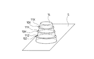
図8及び図9は本発明に係るタイヤ劣化判定具の更に他の変形例を示すものである。図8においては、タイヤ内面Sにはシート状の成形体11(11A,11B,11C)からなる複数個のタイヤ劣化判定具10(10A,10B,10C)が装着されており、これらタイヤ劣化判定具10A,10B,10Cに与えられた初期歪の値が互いに異なっている。一方、図9においては、タイヤ内面Sに共通の突起14が設けられており、該突起14に対してリング状の成形体11(11X,11Y,11Z)からなる複数個のタイヤ劣化判定具10(10X,10Y,10Z)が装着されており、これらタイヤ劣化判定具10X,10Y,10Zに与えられた初期歪の値が互いに異なっている。
8 and 9 show still another modified example of the tire deterioration determining tool according to the present invention. In FIG. 8, a plurality of tire deterioration determining tools 10 (10A, 10B, 10C) made of sheet-shaped molded bodies 11 (11A, 11B, 11C) are mounted on the tire inner surface S, and these tire deterioration determinations are performed. The initial strain values given to the
このように初期歪の値が互いに異なる複数個のタイヤ劣化判定具10を設置した場合、劣化度合いに応じてタイヤ劣化判定具10が初期歪の値が大きいものから順次破断するので、空気入りタイヤの劣化度合いを精密に判定することができる。例えば、上述のように3種類のタイヤ劣化判定具10を配設するにあたって、1番目に大きな初期歪をS1(%)とし、2番目に大きな初期歪をS2(%)とし、3番目に大きな初期歪をS3(%)としたとき、S1/S2≧1.2、S2/S3≧1.2の関係を満足することが好ましい。また、初期歪の値が互いに異なるタイヤ劣化判定具10を容易に判別するために、初期歪の値が互いに異なるタイヤ劣化判定具10を異なる色で着色することも有効である。
When a plurality of tire
以下、上述したタイヤ劣化判定具10を用いたタイヤ劣化判定方法について詳細に説明する。先ず、空気入りタイヤにおいて、タイヤ内面Sに対してタイヤ劣化判定具10を初期歪が与えられた状態で装着する。タイヤ劣化判定具10は空気入りタイヤの製造直後に装着しても良く、或いは、空気入りタイヤの使用開始時に装着しても良い。次いで、タイヤ使用開始後の任意の時点でタイヤ劣化判定具10の破断状態を確認する。タイヤ使用開始後の任意の時点とは、例えば、タイヤ使用過程において任意の走行距離に到達した時点、更生作業を行う時点又はタイヤを廃棄する時点である。そして、タイヤ劣化判定具10の破断状態に基づいて空気入りタイヤの劣化度合いを判定する。タイヤ劣化判定具10に破断が生じている場合、その空気入りタイヤの劣化が十分に進行していると判断される。
Hereinafter, the tire deterioration determination method using the tire
タイヤ劣化判定具10の劣化進行速度は成形体11を構成するゴム組成物の配合に基づいて任意に設定することができる。そのため、成形体11を構成するゴム組成物の配合を調整することにより、判定すべき劣化度合いを調整することが可能である。また、タイヤ劣化判定具10の初期歪を調整することにより、判定すべき劣化度合いを調整することが可能である。これにより、タイヤ劣化判定具10の破断状態に基づいて空気入りタイヤの劣化度合いを簡単に判定することができる。
The deterioration progress rate of the tire
以下、上述したタイヤ劣化判定具10を用いたタイヤ更生可否判定方法について詳細に説明する。空気入りタイヤを更生する場合、その空気入りタイヤが台タイヤとして再利用可能であるか否かを判定する必要があるが、そのような判定をタイヤ劣化判定具10により行うことができる。
Hereinafter, a tire rehabilitation determination method using the above-described tire
ここで、空気入りタイヤの内部パーツの残存耐久性に対応するように調整されたタイヤ劣化判定具10を用意する。即ち、空気入りタイヤの内部パーツの残存耐久性は劣化に伴って徐々に低下し、台タイヤとして再利用可能と判断される最低限の残存耐久性に至り、更には台タイヤとして再利用不可能な残存耐久性に至る。これに対して、使用される空気入りタイヤが台タイヤとして再利用可能と判断される最低限の残存耐久性に至る以前に破断が生じるようにタイヤ劣化判定具10の劣化特性と初期歪を適正化する。
Here, the tire
タイヤ更生可否を判定する場合、タイヤ内面Sに装着されたタイヤ劣化判定具10をタイヤ更生時に目視により確認する。そして、タイヤ劣化判定具10の破断状態に基づいて空気入りタイヤの更生可否を判定する。タイヤ劣化判定具10が破断している場合、台タイヤとして不適当であると判断される。一方、タイヤ劣化判定具10が破断していない場合、台タイヤとして適当であると判断される。これにより、タイヤ劣化判定具10の破断状態に基づいて空気入りタイヤの更生可否を簡単に判定することができる。
When determining whether tire regeneration is possible, the tire
タイヤサイズ11R22.5の空気入りタイヤにおいて、以下のように構造が異なるタイヤ劣化判定具を備えた実施例1〜5のタイヤを作製した。タイヤ劣化判定具はタイヤ赤道位置においてタイヤ内面に対して装着した。 In the pneumatic tire of tire size 11R22.5, tires of Examples 1 to 5 including tire deterioration determining tools having different structures as described below were produced. The tire deterioration determination tool was attached to the tire inner surface at the tire equator position.
実施例1のタイヤは、図1に示すように、シート状の成形体からなるタイヤ劣化判定具を備え、該タイヤ劣化判定具を初期歪が与えられた状態で粘着層を介してタイヤ内面に貼着したものである。 As shown in FIG. 1, the tire of Example 1 includes a tire deterioration determination tool made of a sheet-like molded body, and the tire deterioration determination tool is applied to the tire inner surface through an adhesive layer in a state where an initial strain is applied. Attached.
実施例2のタイヤは、図5に示すように、シート状の成形体からなるタイヤ劣化判定具を備え、該タイヤ劣化判定具を初期歪が与えられた状態で粘着層を介してタイヤ内面に貼着し、その成形体にタイヤ内面とは異なる色に着色された着色部を設けたものである。 As shown in FIG. 5, the tire of Example 2 includes a tire deterioration determination tool made of a sheet-like molded body, and the tire deterioration determination tool is applied to the tire inner surface through an adhesive layer in a state where an initial strain is applied. A colored portion colored by a color different from the inner surface of the tire is provided on the molded body.
実施例3のタイヤは、図6に示すように、タイヤ内面に形成された突起を備えると共に、リング状の成形体からなるタイヤ劣化判定具を備え、該タイヤ劣化判定具を突起の周囲に嵌め合せて初期歪が与えられた状態でタイヤ内面に装着したものである。 As shown in FIG. 6, the tire of Example 3 includes a protrusion formed on the inner surface of the tire and a tire deterioration determination tool made of a ring-shaped molded body, and the tire deterioration determination tool is fitted around the protrusion. In addition, the tire is mounted on the inner surface of the tire with initial strain applied.
実施例4のタイヤは、図8に示すように、シート状の成形体からなる複数個のタイヤ劣化判定具を備え、これらタイヤ劣化判定具を初期歪が与えられた状態で粘着層を介してタイヤ内面に貼着し、タイヤ劣化判定具に与えられた初期歪の値を互いに異ならせたものである。 As shown in FIG. 8, the tire of Example 4 includes a plurality of tire deterioration determination tools made of a sheet-like molded body, and these tire deterioration determination tools are provided with an initial strain through an adhesive layer. The initial strain values attached to the tire inner surface and given to the tire deterioration determination tool are different from each other.
実施例5のタイヤは、図9に示すように、タイヤ内面に形成された突起を備えると共に、リング状の成形体からなる複数個のタイヤ劣化判定具を備え、これらタイヤ劣化判定具を突起の周囲に嵌め合せて初期歪が与えられた状態でタイヤ内面に装着し、タイヤ劣化判定具に与えられた初期歪の値を互いに異ならせたものである。 As shown in FIG. 9, the tire of Example 5 includes protrusions formed on the inner surface of the tire and a plurality of tire deterioration determination tools made of a ring-shaped molded body. The tire is fitted to the periphery and attached to the inner surface of the tire in a state where an initial strain is applied, and the values of the initial strain applied to the tire deterioration determination tool are different from each other.
これら実施例1〜5のタイヤを実際に使用し、タイヤ劣化判定具の破断状態を経時的に調べた。その結果、使用時間が増大するに伴ってタイヤ劣化判定具が適時破断した。このことからも明らかなように、実施例1〜5のタイヤ劣化判定具によれば、空気入りタイヤの劣化度合いを簡単に判定することができ、その空気入りタイヤが更生可能であるか否かを簡単に判定することができる。 The tires of Examples 1 to 5 were actually used, and the rupture state of the tire deterioration determination tool was examined over time. As a result, as the usage time increased, the tire deterioration determination tool broke in a timely manner. As is clear from this, according to the tire deterioration determination tools of Examples 1 to 5, it is possible to easily determine the degree of deterioration of the pneumatic tire, and whether or not the pneumatic tire can be rehabilitated. Can be easily determined.
1 トレッド部
2 サイドウォール部
3 ビード部
4 カーカス層
5 ビードコア
6 ビードフィラー
7 ベルト層
10 タイヤ劣化判定具
11 成形体
12 粘着層
13 着色部
14 突起
15 溝
DESCRIPTION OF SYMBOLS 1
Claims (8)
Priority Applications (1)
| Application Number | Priority Date | Filing Date | Title |
|---|---|---|---|
| JP2016009630A JP6686463B2 (en) | 2016-01-21 | 2016-01-21 | Pneumatic tire, tire deterioration determination method, and tire rehabilitation possibility determination method |
Applications Claiming Priority (1)
| Application Number | Priority Date | Filing Date | Title |
|---|---|---|---|
| JP2016009630A JP6686463B2 (en) | 2016-01-21 | 2016-01-21 | Pneumatic tire, tire deterioration determination method, and tire rehabilitation possibility determination method |
Publications (2)
| Publication Number | Publication Date |
|---|---|
| JP2017128252A true JP2017128252A (en) | 2017-07-27 |
| JP6686463B2 JP6686463B2 (en) | 2020-04-22 |
Family
ID=59395945
Family Applications (1)
| Application Number | Title | Priority Date | Filing Date |
|---|---|---|---|
| JP2016009630A Active JP6686463B2 (en) | 2016-01-21 | 2016-01-21 | Pneumatic tire, tire deterioration determination method, and tire rehabilitation possibility determination method |
Country Status (1)
| Country | Link |
|---|---|
| JP (1) | JP6686463B2 (en) |
Cited By (1)
| Publication number | Priority date | Publication date | Assignee | Title |
|---|---|---|---|---|
| CN111565944A (en) * | 2017-12-29 | 2020-08-21 | 倍耐力轮胎股份公司 | Tyre for vehicle wheels comprising an anchoring element for anchoring an object to the inner surface of the tyre and method for manufacturing said tyre |
Citations (5)
| Publication number | Priority date | Publication date | Assignee | Title |
|---|---|---|---|---|
| JP2006327469A (en) * | 2005-05-27 | 2006-12-07 | Yokohama Rubber Co Ltd:The | Tire deterioration determination unit and forecasting method of tire life using the unit |
| JP2010179824A (en) * | 2009-02-06 | 2010-08-19 | Yokohama Rubber Co Ltd:The | Tire degradation determining tool and pneumatic tire using the same |
| JP2011088558A (en) * | 2009-10-23 | 2011-05-06 | Yokohama Rubber Co Ltd:The | Tire deterioration determination system, pneumatic tire, and method of manufacturing retreaded tire |
| JP2012013640A (en) * | 2010-07-05 | 2012-01-19 | Yokohama Rubber Co Ltd:The | Determination system of deterioration of tire and manufacturing method of reclaimed tire |
| JP2012116417A (en) * | 2010-12-03 | 2012-06-21 | Yokohama Rubber Co Ltd:The | Pneumatic tire, tire deterioration state determining system and tire deterioration state determining method |
-
2016
- 2016-01-21 JP JP2016009630A patent/JP6686463B2/en active Active
Patent Citations (5)
| Publication number | Priority date | Publication date | Assignee | Title |
|---|---|---|---|---|
| JP2006327469A (en) * | 2005-05-27 | 2006-12-07 | Yokohama Rubber Co Ltd:The | Tire deterioration determination unit and forecasting method of tire life using the unit |
| JP2010179824A (en) * | 2009-02-06 | 2010-08-19 | Yokohama Rubber Co Ltd:The | Tire degradation determining tool and pneumatic tire using the same |
| JP2011088558A (en) * | 2009-10-23 | 2011-05-06 | Yokohama Rubber Co Ltd:The | Tire deterioration determination system, pneumatic tire, and method of manufacturing retreaded tire |
| JP2012013640A (en) * | 2010-07-05 | 2012-01-19 | Yokohama Rubber Co Ltd:The | Determination system of deterioration of tire and manufacturing method of reclaimed tire |
| JP2012116417A (en) * | 2010-12-03 | 2012-06-21 | Yokohama Rubber Co Ltd:The | Pneumatic tire, tire deterioration state determining system and tire deterioration state determining method |
Cited By (1)
| Publication number | Priority date | Publication date | Assignee | Title |
|---|---|---|---|---|
| CN111565944A (en) * | 2017-12-29 | 2020-08-21 | 倍耐力轮胎股份公司 | Tyre for vehicle wheels comprising an anchoring element for anchoring an object to the inner surface of the tyre and method for manufacturing said tyre |
Also Published As
| Publication number | Publication date |
|---|---|
| JP6686463B2 (en) | 2020-04-22 |
Similar Documents
| Publication | Publication Date | Title |
|---|---|---|
| JP5071204B2 (en) | Pneumatic tire | |
| RU2602879C2 (en) | Self-sealing tire for vehicle wheels | |
| JP5550039B2 (en) | Pneumatic tire | |
| EP1424221A1 (en) | Pneumatic tire and method of producing the same | |
| EP2522496B1 (en) | Method for manufacturing a tire with a colored sidewall and tire with a colored sidewall | |
| JP2009166650A (en) | Retreaded tire and method of retreading tire | |
| JP5379313B2 (en) | Tire manufacturing method and tire manufacturing method | |
| US20130333819A1 (en) | Tire casing | |
| JPH06183224A (en) | Pneumatic radial tire for heavy load | |
| JP6686463B2 (en) | Pneumatic tire, tire deterioration determination method, and tire rehabilitation possibility determination method | |
| EP2014487B1 (en) | Pneumatic tire | |
| JP6686465B2 (en) | Tire deterioration judging tool, pneumatic tire equipped with tire deterioration judging tool, tire deterioration judging method, and tire rehabilitation possibility judging method | |
| WO2020044283A1 (en) | Tyre for vehicle wheels | |
| JP6838283B2 (en) | Tire deterioration judgment tool and tire rehabilitation possibility judgment method using it | |
| CN103384604B (en) | Tire | |
| JP2015174459A (en) | Pneumatic tire | |
| JP6786867B2 (en) | Tire deterioration judgment device and pneumatic tire equipped with it | |
| JP6686464B2 (en) | Tire deterioration determination device and pneumatic tire including the same | |
| JP6707982B2 (en) | Tire deterioration determination device and pneumatic tire including the same | |
| EP3694938B1 (en) | Tire for vehicle wheels | |
| JP6704085B2 (en) | Conductive rubber strip | |
| JP6652828B2 (en) | Pneumatic tire | |
| JP2007537098A (en) | Pneumatic tire | |
| JPH09164606A (en) | Solid tire rehabilitation method | |
| CN1984786A (en) | Pneumatic tyre |
Legal Events
| Date | Code | Title | Description |
|---|---|---|---|
| A621 | Written request for application examination |
Free format text: JAPANESE INTERMEDIATE CODE: A621 Effective date: 20190116 |
|
| RD07 | Notification of extinguishment of power of attorney |
Free format text: JAPANESE INTERMEDIATE CODE: A7427 Effective date: 20190731 |
|
| A977 | Report on retrieval |
Free format text: JAPANESE INTERMEDIATE CODE: A971007 Effective date: 20200122 |
|
| TRDD | Decision of grant or rejection written | ||
| A01 | Written decision to grant a patent or to grant a registration (utility model) |
Free format text: JAPANESE INTERMEDIATE CODE: A01 Effective date: 20200303 |
|
| A61 | First payment of annual fees (during grant procedure) |
Free format text: JAPANESE INTERMEDIATE CODE: A61 Effective date: 20200316 |
|
| R150 | Certificate of patent or registration of utility model |
Ref document number: 6686463 Country of ref document: JP Free format text: JAPANESE INTERMEDIATE CODE: R150 |
|
| R250 | Receipt of annual fees |
Free format text: JAPANESE INTERMEDIATE CODE: R250 |
|
| S531 | Written request for registration of change of domicile |
Free format text: JAPANESE INTERMEDIATE CODE: R313531 |
|
| R350 | Written notification of registration of transfer |
Free format text: JAPANESE INTERMEDIATE CODE: R350 |
|
| R250 | Receipt of annual fees |
Free format text: JAPANESE INTERMEDIATE CODE: R250 |
|
| R250 | Receipt of annual fees |
Free format text: JAPANESE INTERMEDIATE CODE: R250 |
|
| R250 | Receipt of annual fees |
Free format text: JAPANESE INTERMEDIATE CODE: R250 |