JP2017128902A - Water stop plate and water stop structure using the same - Google Patents
Water stop plate and water stop structure using the same Download PDFInfo
- Publication number
- JP2017128902A JP2017128902A JP2016008345A JP2016008345A JP2017128902A JP 2017128902 A JP2017128902 A JP 2017128902A JP 2016008345 A JP2016008345 A JP 2016008345A JP 2016008345 A JP2016008345 A JP 2016008345A JP 2017128902 A JP2017128902 A JP 2017128902A
- Authority
- JP
- Japan
- Prior art keywords
- water stop
- stop plate
- water
- fibers
- fiber
- Prior art date
- Legal status (The legal status is an assumption and is not a legal conclusion. Google has not performed a legal analysis and makes no representation as to the accuracy of the status listed.)
- Pending
Links
Images


Landscapes
- Special Wing (AREA)
- Buildings Adapted To Withstand Abnormal External Influences (AREA)
Abstract
【課題】緊急時に1人でも簡単に作業ができ、普段のメンテナンスも必要なく確実に止水ができる止水板をとそれを用いた止水構造を提供する。【解決手段】一方向に繊維を配向させ樹脂で固定した長方形の繊維樹脂複合体からなり、繊維方向に沿った長方形の中心線が最突出部となるように湾曲させた止水板を、地下出入口の開口部の左右両端の止水板設置高さに合わせて一対の連結具を予め固定具で強固に固定しておく。一対の連結具にはそれぞれが対称形になるように水平位置より前方に傾斜する固定溝を有し、固定溝に止水板の各端部を挿入固定して螺合し、水の流入方向に向かって凸状に湾曲させた止水構造を提供する。【選択図】図7[PROBLEMS] To provide a water stop plate and a water stop structure using the water stop plate that can be easily operated by one person in an emergency and can be surely stopped without the need for ordinary maintenance. A waterstop plate made of a rectangular fiber-resin composite in which fibers are oriented in one direction and fixed with a resin, and curved so that the center line of the rectangle along the fiber direction is the most protruding portion, A pair of couplers are firmly fixed in advance with fixtures in accordance with the water stop plate installation heights at the left and right ends of the opening of the entrance / exit. Each of the pair of couplers has a fixing groove that is inclined forward from the horizontal position so as to be symmetrical, and each end of the water stop plate is inserted and fixed into the fixing groove and screwed together, so that the water inflow direction A water stop structure curved in a convex shape toward the surface is provided. [Selection] Figure 7
Description
本発明は、繊維樹脂複合体を湾曲させて得られた止水板及びそれを用いた止水構造に関するものである。 The present invention relates to a water stop plate obtained by curving a fiber resin composite and a water stop structure using the water stop plate.
近年、ゲリラ豪雨や巨大台風等の影響で低い土地での浸水が発生し、特に地下街、地下駐車場、地下鉄等の出入口から水が浸入すると、都市機能がマヒし甚大な被害が生じる。 In recent years, inundation occurs in low land due to the influence of guerrilla heavy rains and huge typhoons. Especially when water enters from the entrances of underground malls, underground parking lots, subways, etc., urban functions are paralyzed and serious damage occurs.
これを防止するために、出入口で水の侵入を遮断するための止水装置が種々使用されるが、従来は、止水板としてフレーム形状の枠に板を張り、厚みのあるパネルを緊急時に出入口部分に固定したり、格納しているものをレールで引き出したり、蝶番ヒンジで開閉する等して設置していた。 In order to prevent this, various water stop devices for blocking water intrusion at the entrance and exit are used. Conventionally, a plate is attached to a frame-shaped frame as a water stop plate, and a thick panel is used in an emergency. It was installed by fixing it at the entrance / exit part, pulling out the stored item with a rail, or opening and closing it with a hinge hinge.
例えば、特許文献1では、建造物の入口両側に溝を設けた柱を立て、この溝に弾性止水ゴムを設けた防水板を嵌めこんで、柱に防水板を圧接することで水の侵入を防ぐ構造であり、これによれば、防水板はアルミ製の中空構造で内部をステンレス板で補強したもので、柱間を一枚で遮蔽するための大きな板材であり、多人数での作業が必要で、緊急時に迅速な対応がし難い。
For example, in
特許文献2では、開口部両端の側壁に止水パネルが連結部材で連結され、通常は側壁部分に収納され、緊急時には止水パネルを引き出して中央部で固定し開口部を遮蔽する止水扉が得られことができる。これによれば、特許文献1の問題点が解消され一人でも簡単に作業ができるという利点がある。
In
しかし、この止水扉では構造が複雑になり常にメンテナンスをしなければ、故障によって緊急時に遮蔽できない場合もあり、さらに、止水パネルが中央で精度よく接合しなければ、接合部分から水が浸入するおそれもある。 However, the structure of this water stop door is complicated, and if it is not always maintained, it may not be able to be blocked in an emergency due to a failure. Furthermore, if the water stop panel does not join accurately at the center, water will enter from the joint. There is also a risk.
本発明は斯かる点に鑑みてなされたものであり、その目的は、緊急時に1人でも簡単に作業ができ、普段のメンテナンスも必要なく確実に止水ができる止水板とそれを用いた止水構造を提供することにある。 The present invention has been made in view of such a point, and an object of the present invention is to use a water stopping plate that can be easily operated by one person in an emergency, and can reliably stop water without requiring normal maintenance, and the same. The purpose is to provide a water stop structure.
上記の目的の達成のため、請求項1に記載の発明による止水板は、樹脂と繊維とからなる長方形の繊維樹脂複合体において、主たる繊維の配向方向を鉛直方向とし鉛直方向の中心線が最突出部となるように湾曲させたことを特徴とする。
In order to achieve the above object, the waterstop plate according to the invention described in
請求項2に記載の発明による止水板は、請求項1に記載の鉛直方向に配向する繊維の20〜50%を水平方向に配向させたことを特徴とする。
The waterstop plate according to the invention described in
請求項3に記載の発明による止水板において、請求項1又は請求項2に記載の繊維は、一方向に繊維を配向させたシートを複数層積層させてなることを特徴とする。
In the waterstop plate according to the invention described in
請求項4に記載の発明による止水板は、請求項1から請求項3までのいずれか1項に記載の繊維の少なくとも一部が炭素繊維であることを特徴とする。 A waterstop plate according to a fourth aspect of the present invention is characterized in that at least a part of the fibers according to any one of the first to third aspects is a carbon fiber.
請求項5に記載の発明による止水板を用いた止水構造は、請求項1から請求項4までのいずれか1項に記載の止水板を開口部の左右端から水の流入方向に向かって凸状に湾曲させた状態で、止水板の両端部を一対の連結具を介して開口部の左右端に固定したことを特徴とする。
The water stop structure using the water stop plate according to the invention of
請求項6に記載の発明による止水構造は、請求項5に記載の一対の連結具にはそれぞれが対称形になるように水平位置より前方に傾斜する固定溝を有し、当該固定溝に止水板の各端部を挿入固定したことを特徴とする。 According to a sixth aspect of the present invention, there is provided the water stop structure according to the fifth aspect of the present invention, wherein the pair of couplers has a fixing groove that is inclined forward from the horizontal position so that each of the connecting tools is symmetrical. Each end of the water stop plate is inserted and fixed.
本発明の止水板は、主たる繊維の配向方向を鉛直方向とし樹脂で固定した長方形の繊維樹脂複合体からなるため、繊維に直接加わらない鉛直方向の力に対して容易に変形し、繊維に直接加わる水平方向の力に対しては変形し難いため、鉛直方向の中心線が最突出部となるように容易に湾曲させることができる。また、止水板を自由に湾曲できるので、通常は平板で保管し、緊急時には湾曲させて使用することもできるので、保管も場所をとらず、湾曲した状態での板の破損や変形を防止できる。 The water stop plate of the present invention is composed of a rectangular fiber resin composite in which the orientation direction of the main fibers is the vertical direction and fixed with resin, so that it easily deforms against the force in the vertical direction not directly applied to the fibers, Since it is difficult to be deformed by a horizontal force applied directly, it can be easily bent so that the center line in the vertical direction becomes the most protruding portion. In addition, since the water stop plate can be bent freely, it is usually stored as a flat plate and can be used by bending it in an emergency, so it can be stored and saves space, preventing damage and deformation of the plate in a curved state. it can.
請求項2の発明では、請求項1の発明に記載の鉛直方向に配向する繊維の20〜50%を水平方向に配向させたことにより、請求項1で得られる効果を保持したまま水平方向の力に対してもある程度の強度が得られる。また、繊維の配向割合を20〜50%の間で調整することで、成形性と止水板全体の均一な強度バランスを得ることができる。
In the invention of
請求項3の発明では、繊維樹脂複合体に用いられる鉛直方向または水平方向の一方向に配向した繊維として、一方向に繊維を配向させたシートを複数層積層させてなるので、繊維の配向割合をシートの配向方向と枚数で容易に調整することができる。
In the invention of
請求項4の発明では、繊維の少なくとも一部を炭素繊維とすることで、若干コストは上がるもののガラス繊維等に比較してより軽量高強度で寸法安定性に優れた止水板が得られる。
In the invention of
請求項5の発明では、止水板を開口部の左右端から水の流入方向に向かって凸状に湾曲させた状態で、止水板の両端部を一対の連結具を介して開口部の左右端に固定することで、止水板にぶつかる水流の一部が止水板に沿って横方向に流れ水圧が低くなり、より大量の水にも耐えることができる。
In the invention of
請求項6の発明では、一対の連結具にはそれぞれが対称形になるように水平位置より前方に傾斜する固定溝を有し、当該固定溝に止水板の各端部を挿入固定したことで、水の流入方向に向かって止水板をアーチ状に湾曲させることができ、請求項5で得られる効果が容易に得られる。
In the invention of claim 6, the pair of couplers each have a fixing groove that is inclined forward from the horizontal position so as to be symmetrical, and each end of the water stop plate is inserted and fixed in the fixing groove. Thus, the water stop plate can be curved in an arch shape toward the water inflow direction, and the effect obtained in
以下、本発明の実施形態を図面に基づいて詳細に説明する。以下の実施形態の説明は、本質的に例示に過ぎず、本発明、その適用物或いはその用途を制限することを意図するものでは全くない。 Hereinafter, embodiments of the present invention will be described in detail with reference to the drawings. The following description of the embodiments is merely illustrative in nature and is not intended to limit the present invention, its application, or its use at all.
図1は本発明の止水板1を示す斜視図であり、止水板1は一方向に繊維を配向させ樹脂で固定した例えばFRPやCFRPのような繊維樹脂複合体であり、基本的に繊維の配向方向は、鉛直方向の配向1aである。これによって、止水板は繊維を直交する(折り曲げる)方向には曲げ難く、繊維方向には曲げ易い。この性質を利用すれば止水板1は、中心線1cを長方形の成形体1の最突出部分として手でも容易に湾曲させることができる。
FIG. 1 is a perspective view showing a
従来の止水板では、湾曲したものが必要な場合は、事前に型材を用いて成形していたが、高価な型材を使用する必要があり、成形にも手間がかかっていた。また、湾曲させた止水板は保管するにも場所を取ったり、保管中に変形、破損して使用できなくなる場合があったが、本発明の成形体による止水板は事前に成形する必要がなく、現場の寸法に応じて簡単にその場で湾曲した止水板が得られる。 In the conventional water stop plate, when a curved one is necessary, it is molded using a mold material in advance. However, it is necessary to use an expensive mold material, and it takes time and effort to mold. In addition, the curved waterstop may take up space for storage or may become unusable due to deformation or breakage during storage, but the waterstop using the molded body of the present invention must be molded in advance. Therefore, it is possible to easily obtain a water stop plate that is curved on the spot according to the size of the site.
一方で、成形し易いということは、水圧によって変形し易いということであるため、繊維のない樹脂の部分に水圧がかかると変形し易くなるが、一方向(鉛直方向)に配向させた繊維1aの一部を直交する方向(水平方向に配向する繊維1b)とすることで、いろいろな方向からの水圧に対応できる。幅、長さ両方向への繊維の配向の割合は、成形のし易さと強度のバランスを取らなければならないが、鉛直方向に配向する繊維1aの20〜50%を水平方向に配向する繊維1bとするのが好ましい。なお、図1では便宜的に繊維を実線1a、1bで表しているが、実際は樹脂に複合一体化して表面には表れない。また、本数も実際とは異なっており構造を分かり易いように模式的に表したものである。 On the other hand, the fact that it is easy to mold means that it is easily deformed by water pressure. Therefore, it is easy to be deformed when water pressure is applied to a resin portion without fibers, but the fiber 1a oriented in one direction (vertical direction). It is possible to cope with water pressure from various directions by setting a part of the fiber to a direction orthogonal to each other (fiber 1b oriented in the horizontal direction). The ratio of the orientation of the fibers in both the width and length directions must balance the ease of molding and the strength, but 20 to 50% of the fibers 1a oriented in the vertical direction and the fibers 1b oriented in the horizontal direction It is preferable to do this. In FIG. 1, the fibers are represented by solid lines 1a and 1b for the sake of convenience. Also, the number is different from the actual one, and the structure is schematically shown for easy understanding.
止水板1に用いる繊維樹脂複合体(比重1.5〜2.0)は、従来の止水板で用いられた鉄(比重7.8)や軽量のアルミニウム(比重2.7)に比べて軽量であり一人でも作業が可能である。
繊維としてはガラス繊維等が使用できるが、高強度の炭素繊維を用いることでより軽量高強度の繊維樹脂複合体すなわち止水板1が得られる。
The fiber resin composite (specific gravity 1.5 to 2.0) used for the
Glass fiber or the like can be used as the fiber, but a lighter and stronger fiber-resin composite, that is, the
繊維樹脂複合体に用いる繊維としては、ガラス繊維や炭素繊維など各種の補強繊維を短繊維または長繊維でも一方向に繊維を配向させたシートを複数層積層させることができる。これによって、成形のし易さと強度のバランスを取るために鉛直方向及び水平方向の繊維の配向割合を容易に調整することができる。また、積層する繊維シートの種類を例えば、表裏層を鉛直方向に配向させた炭素繊維のシートとし、芯層をガラス繊維シートを複数層繊維配向を適宜組合わせることで、強度やコストのバランスの取れた止水板を得ることができる。 As the fiber used for the fiber resin composite, a plurality of sheets in which various reinforcing fibers such as glass fiber and carbon fiber are oriented in one direction even with short fibers or long fibers can be laminated. Accordingly, the orientation ratio of the fibers in the vertical direction and the horizontal direction can be easily adjusted in order to balance the ease of forming and the strength. In addition, the type of fiber sheet to be laminated is, for example, a carbon fiber sheet in which the front and back layers are oriented in the vertical direction, and the core layer is appropriately combined with a glass fiber sheet and a multi-layer fiber orientation, thereby achieving a balance of strength and cost. A water stop plate can be obtained.
通常のFRPでは、さまざまな形状に柔軟に対応でき強度的にも優れるため、成形型に繊維樹脂複合した強化基材をあらかじめ賦形させ、人手によって樹脂をハケやローラーで含浸させ、脱泡しながら所定の厚さまで積層するハンドレイアップ成形が用いられるが、
炭素繊維が用いられたCFRPでは炭素繊維が軽量のためハケ等にまとわりつき、製品とならない場合が多いため、レジンインフュージョン・オートクレープ・プレス等の成型 方法が必要となり、いずれも副資材や製造の工程に長時間必要なため結果高額になる。
Since ordinary FRP can flexibly adapt to various shapes and is excellent in strength, a reinforcing base made of fiber resin composite is pre-shaped in a mold, and the resin is manually impregnated with a brush or roller and defoamed. While hand lay-up molding is used to laminate to a predetermined thickness,
Since CFRP using carbon fiber is light in weight, it often clings to brushes, etc., and does not become a product. The process is expensive because it takes a long time.
したがって、今回の成型方法は、ハンドレイアップで道具にまとわりつかずに塗布する方法である。その手法は下記の順に従って行われる。
1. 虫除けなどのメッシュ材を用意し、カーボン材に樹脂を塗布する前に被せ樹脂を塗布する。
2.脱包ローラーにて内包されている気泡を外部へ、
3.1・2を必要回数繰り返す。
4.ボリエステルフィルム等で表面を覆い、
5.FRP成形同様に、必要厚スペーサーを配して金属製の板を湾曲させ中央部から順に端部へと脱包し硬化を待つ。
Therefore, this molding method is a method of applying without tying up to the tool by hand lay-up. The method is performed in the following order.
1. Prepare a mesh material such as insect repellent, and apply the covering resin before applying the resin to the carbon material.
2. Air bubbles contained in the unpacking roller to the outside
3. Repeat steps 1 and 2 as many times as necessary.
4). Cover the surface with a polyester film,
5. Similar to the FRP molding, a necessary thickness spacer is arranged to bend the metal plate, decapsulate from the center to the end, and wait for curing.
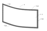
次に、図1に示す止水板本体11を図2に示す止水板1として用いる方法を示す。平板状の止水板本体11は前述したように、繊維に沿った方向に湾曲できるが、通常は平板状で保管する。使用する際には、上下端部水平方向全長に亘って水平側パッキン12を設ける。下端部の水平側パッキン12は床部分との防水材として、上端部の水平側パッキン12は止水板1を上下方向に積み重ねる際の防水材として機能する。したがって、止水板1を単独で使用する場合は下端側一方のみで良い。
Next, a method of using the water
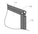
鉛直方向の鉛直側パッキン13は止水板1を後述する連結具2に固定する際に、連結具2から水が浸入しないように止水板本体11の左右端部全長に亘って固定される。その取付構造の詳細を図3に示す。これらのパッキンの材質は特に限定はしないが、例えば各種ゴム類(SBR,EPDM、NBR、シリコーン)、熱可塑性エラストマー等、一般的に使用されているものを用いることができる。また、大きさや形状は止水できれば特に限定されないが、溝等を設けて止水板に嵌め込む形状にしておけば、保管時や劣化時に取り外すことができる。
The vertical packing 13 in the vertical direction is fixed over the entire length of the right and left end portions of the water
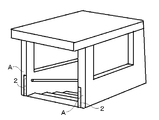
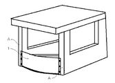
次に、止水板1を必要とする出入り口に装着する方法について説明する。図4は通常状態の地下出入口の斜視図であり、図5は同じ地下出入口に止水板を設置した場合の斜視図である。地下出入口の開口部の左右両端の止水板設置高さに合わせて一対の連結具2を予めビス等で強固に固定しておく。
Next, a method for attaching the
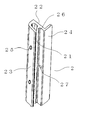
図6は連結具2を示す斜視図であり、出入口への設置部22、止水板を押さえるカバー部23、設置部から直角に突設し左右開口部に当設させて連結具2を安定して固定することができる垂直固定片24、鉛直側パッキン13が密着して防水機能を有する止水突部26、カバー部と止水突部から形成される固定溝21、連結具をネジ等で出入口に固定する固定孔部27、止水板1を連結具2に固定するネジを螺合するためのタップを切ったネジ孔25からなる。
FIG. 6 is a perspective view showing the
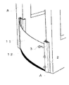
図7及び図8に示すように、連結具2は前方に突出するカバー部23により、止水板1を固定する固定溝21が水平位置より前方に傾斜するように形成されると共に、一対の連結具2はそれぞれが対称形になるように開口部の左右端Aにコンクリート釘等の固定具4で強固に固定する。そして、止水板1を中央部1cが前方に凸状になるように湾曲させてから、カバー部23に沿わせて挿入することで、鉛直側パッキン13は押し潰されその弾性による反発力で、止水板1はカバー部23の裏面に圧着されると共に防水機能を有する。この時、止水板1は左右の連結具2から前方(水の流入方向に向かって)に凸状に湾曲した状態で固定することができ、ネジ3を矢印で示すようにネジ孔25に螺合させネジ3の先端で止水板1を押すことにより鉛直側パッキン13と連結具2との密着性をより高めると共に動かないように固定する。
As shown in FIGS. 7 and 8, the
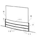
止水板1と床との間は下端部の水平側パッキン12により、床面に多少の不陸があっても水の侵入を防ぐことができる。なお、上側の水平側パッキン12については、図9に示すように地下出入口の別の実施形態として、開口部の左右端Bに止水板1を上下に積み重ねて設置する際に、上下の止水板の間から水が浸入しないように設ける。侵入高さを高くする場合や開口幅が大きい場合も1枚の止水板の高さを低くすることで、1枚当たりの重量を重くすることなく緊急時の作業性を低下させることがない。
The
このようにして設置された止水板は、左右開口部から水の流入方向に向かって凸状に湾曲させることにより、止水板にぶつかる水流の一部が止水板に沿って横方向に流れ水圧が低下し、より大量の水にも耐えることができる。 The water stop plate installed in this way is curved in a convex shape from the left and right openings toward the inflow direction of water, so that part of the water flow that hits the water stop plate is laterally along the water stop plate. The flowing water pressure decreases and can withstand a larger amount of water.
本発明は、容易に湾曲させることができる軽量の止水板により、緊急時に1人でも作業ができ、容易に止水構造が得られるので、極めて有用で産業上の利用可能性が高い。 The present invention can be easily bent by a lightweight water stop plate, so that even one person can work in an emergency and can easily obtain a water stop structure. Therefore, the present invention is extremely useful and has high industrial applicability.
1 止水板
12 水平側パッキン
13 鉛直側パッキン
2 連結具
21 固定溝
23 カバー部
24 垂直固定片
25 ネジ孔
26 止水突部
3 止水板固定ネジ
DESCRIPTION OF
26
Claims (6)
Priority Applications (1)
| Application Number | Priority Date | Filing Date | Title |
|---|---|---|---|
| JP2016008345A JP2017128902A (en) | 2016-01-19 | 2016-01-19 | Water stop plate and water stop structure using the same |
Applications Claiming Priority (1)
| Application Number | Priority Date | Filing Date | Title |
|---|---|---|---|
| JP2016008345A JP2017128902A (en) | 2016-01-19 | 2016-01-19 | Water stop plate and water stop structure using the same |
Publications (1)
| Publication Number | Publication Date |
|---|---|
| JP2017128902A true JP2017128902A (en) | 2017-07-27 |
Family
ID=59396694
Family Applications (1)
| Application Number | Title | Priority Date | Filing Date |
|---|---|---|---|
| JP2016008345A Pending JP2017128902A (en) | 2016-01-19 | 2016-01-19 | Water stop plate and water stop structure using the same |
Country Status (1)
| Country | Link |
|---|---|
| JP (1) | JP2017128902A (en) |
Cited By (1)
| Publication number | Priority date | Publication date | Assignee | Title |
|---|---|---|---|---|
| JP2020023801A (en) * | 2018-08-06 | 2020-02-13 | 有限会社トラッド | Water stop plate and water stop structure using the same |
Citations (8)
| Publication number | Priority date | Publication date | Assignee | Title |
|---|---|---|---|---|
| JPH04182503A (en) * | 1990-11-16 | 1992-06-30 | Daiwa Eng:Kk | Land lock |
| JPH0635443U (en) * | 1992-10-13 | 1994-05-13 | 株式会社コンポジットシステム研究所 | Structural materials for construction |
| JP2000263668A (en) * | 1999-03-16 | 2000-09-26 | Toray Ind Inc | FRP sandwich panel and manufacturing method thereof |
| EP1223294A1 (en) * | 2001-01-05 | 2002-07-17 | Gerald Michael Fairbrother | Reversible flood barrier |
| JP2003321810A (en) * | 2002-05-07 | 2003-11-14 | Toray Ind Inc | FRP noise barrier |
| JP2006316461A (en) * | 2005-05-11 | 2006-11-24 | Marushima Sangyo Kk | Water stop device |
| JP2007016456A (en) * | 2005-07-07 | 2007-01-25 | Nippon Frp Kk | Floor support type waterproof door structure |
| US20140212220A1 (en) * | 2013-01-28 | 2014-07-31 | Power Fin Technologies Limited | Flood barrier and method of flood protection |
-
2016
- 2016-01-19 JP JP2016008345A patent/JP2017128902A/en active Pending
Patent Citations (8)
| Publication number | Priority date | Publication date | Assignee | Title |
|---|---|---|---|---|
| JPH04182503A (en) * | 1990-11-16 | 1992-06-30 | Daiwa Eng:Kk | Land lock |
| JPH0635443U (en) * | 1992-10-13 | 1994-05-13 | 株式会社コンポジットシステム研究所 | Structural materials for construction |
| JP2000263668A (en) * | 1999-03-16 | 2000-09-26 | Toray Ind Inc | FRP sandwich panel and manufacturing method thereof |
| EP1223294A1 (en) * | 2001-01-05 | 2002-07-17 | Gerald Michael Fairbrother | Reversible flood barrier |
| JP2003321810A (en) * | 2002-05-07 | 2003-11-14 | Toray Ind Inc | FRP noise barrier |
| JP2006316461A (en) * | 2005-05-11 | 2006-11-24 | Marushima Sangyo Kk | Water stop device |
| JP2007016456A (en) * | 2005-07-07 | 2007-01-25 | Nippon Frp Kk | Floor support type waterproof door structure |
| US20140212220A1 (en) * | 2013-01-28 | 2014-07-31 | Power Fin Technologies Limited | Flood barrier and method of flood protection |
Cited By (1)
| Publication number | Priority date | Publication date | Assignee | Title |
|---|---|---|---|---|
| JP2020023801A (en) * | 2018-08-06 | 2020-02-13 | 有限会社トラッド | Water stop plate and water stop structure using the same |
Similar Documents
| Publication | Publication Date | Title |
|---|---|---|
| KR20120109985A (en) | Construction structure of underground outer wall | |
| KR102195716B1 (en) | Waterproof assembly and pre-manufactured wall panels containing same | |
| KR102119385B1 (en) | The roof panel system of building | |
| JP2017128902A (en) | Water stop plate and water stop structure using the same | |
| JP6941841B2 (en) | A waterstop plate and a method of mounting the waterstop plate using the waterstop plate. | |
| EP3426856A1 (en) | Prefabricated demising wall with external conduit engagement features | |
| KR101271205B1 (en) | All that can be used both sides of signboard frame System | |
| KR102005470B1 (en) | Barrier structure for the opening of the gangform | |
| KR101454010B1 (en) | A hybrid panel for reinforcing concrete structures | |
| CN215443213U (en) | Vertical prefabricated component's auxiliary fixtures that takes one's place | |
| CN206418915U (en) | A kind of attachment means installed applied to container construction window | |
| JP2013139698A (en) | Seismically retrofitted wall, and construction method for the same | |
| JP2019015033A (en) | Waterproof panel and waterproofing device using waterproof panel | |
| JP2019167785A (en) | Inundation prevention device, water cutoff plate and structure | |
| JP6609106B2 (en) | Waterproof structure of building unit | |
| JP7088648B2 (en) | Insulation structure and construction method of insulation structure | |
| JP5238217B2 (en) | Wall panels | |
| JP5806849B2 (en) | Vertical starter | |
| JP5848103B2 (en) | Seismic retrofit walls and methods of constructing seismic retrofit walls | |
| KR20160034836A (en) | Noise reduction window system of gang form | |
| CN106703602B (en) | A kind of attachment device applied to the installation of container construction window | |
| GB2500518A (en) | Fireproof door with phenolic resin core and glass fibre net or glass or carbon fibre cloth layers | |
| CN119737011B (en) | Sectional type building curtain wall structure and construction method thereof | |
| CN221682348U (en) | Stone plastic board with honeycomb structure | |
| CN109577690B (en) | An assembled channel system |
Legal Events
| Date | Code | Title | Description |
|---|---|---|---|
| A621 | Written request for application examination |
Free format text: JAPANESE INTERMEDIATE CODE: A621 Effective date: 20170727 |
|
| A977 | Report on retrieval |
Free format text: JAPANESE INTERMEDIATE CODE: A971007 Effective date: 20180425 |
|
| A131 | Notification of reasons for refusal |
Free format text: JAPANESE INTERMEDIATE CODE: A131 Effective date: 20180522 |
|
| A521 | Request for written amendment filed |
Free format text: JAPANESE INTERMEDIATE CODE: A523 Effective date: 20180723 |
|
| A131 | Notification of reasons for refusal |
Free format text: JAPANESE INTERMEDIATE CODE: A131 Effective date: 20190108 |
|
| A521 | Request for written amendment filed |
Free format text: JAPANESE INTERMEDIATE CODE: A523 Effective date: 20190302 |
|
| A02 | Decision of refusal |
Free format text: JAPANESE INTERMEDIATE CODE: A02 Effective date: 20190827 |