JP2017129295A - Heating cooking device - Google Patents
Heating cooking device Download PDFInfo
- Publication number
- JP2017129295A JP2017129295A JP2016007626A JP2016007626A JP2017129295A JP 2017129295 A JP2017129295 A JP 2017129295A JP 2016007626 A JP2016007626 A JP 2016007626A JP 2016007626 A JP2016007626 A JP 2016007626A JP 2017129295 A JP2017129295 A JP 2017129295A
- Authority
- JP
- Japan
- Prior art keywords
- light
- light source
- air
- light guide
- heating chamber
- Prior art date
- Legal status (The legal status is an assumption and is not a legal conclusion. Google has not performed a legal analysis and makes no representation as to the accuracy of the status listed.)
- Granted
Links
Images


Landscapes
- Electric Stoves And Ranges (AREA)
Abstract
Description
本発明は、グリルやオーブンなどの加熱庫を備えた加熱調理装置に関する。 The present invention relates to a cooking device including a heating chamber such as a grill or an oven.
上述のような加熱庫を備えた加熱調理装置では、加熱調理中に加熱庫内の被調理物の調理進行状況などを目視することが望まれる。ところが、加熱庫には加熱調理中に閉鎖する扉が設けられており、その扉に形成された小さな覗き窓越しに加熱庫内を目視しなければならず、被調理物を観察しづらいという不具合があった。 In the cooking device provided with the heating chamber as described above, it is desired to visually check the cooking progress of the cooking object in the heating chamber during cooking. However, the heating cabinet is provided with a door that closes during cooking, and the inside of the heating cabinet must be observed through a small viewing window formed on the door, making it difficult to observe the object to be cooked. was there.
そこで、加熱庫の天井部に耐熱ガラス板などが嵌め込まれた透光部を設け、その透光部の上方に更にLED等の光源を設け、その光源から照射された光を、透光部を通して加熱庫内に照射して、加熱庫内の被調理物を照明するようにしたものが知られている(例えば、特許文献1参照)。 Therefore, a translucent part in which a heat-resistant glass plate or the like is fitted is provided in the ceiling part of the heating chamber, and a light source such as an LED is further provided above the translucent part, and light emitted from the light source is transmitted through the translucent part. What irradiates the inside of a heating chamber, and illuminates the to-be-cooked object in a heating chamber is known (for example, refer patent document 1).
このように光源により被調理物を照明することによって扉の覗き窓から覗いても被調理物を明瞭に目視することができる。 By illuminating the object to be cooked with the light source in this way, the object to be cooked can be clearly seen even when looking through the viewing window of the door.
上記特許文献1に記載された従来の加熱調理装置では、加熱庫の天井板の上方に所定の距離を存して設置された中仕切り板を設け、その中仕切り板の上面に光源を設置し、中仕切り板と加熱庫の天井板との間に筒状の導光路を配置して、光源から照射された光をこの導光路を通して透光部へと導いている。
In the conventional cooking device described in
そのため、導光路は加熱庫からの輻射熱や高温となった周囲の空気によって加熱されて高温となり、導光路からの熱が光源に伝達されるおそれが生じる。点灯することにより光源自体も発熱するが、外部からの熱が伝達されて光源がさらに高温になると、光源の寿命が損なわれるという問題が生じる。なお、光源を加熱庫から離せば光源が加熱されるという問題はある程度解消されるものの、光源から加熱庫内に照射される光による照明範囲が狭くなり、加熱庫内の被調理物を有効に照明することができなくなる。 For this reason, the light guide path is heated by the radiant heat from the heating chamber or the surrounding air that has become high temperature, and the heat from the light guide path may be transferred to the light source. Although the light source itself also generates heat when turned on, there is a problem in that the life of the light source is impaired when heat from the outside is transmitted and the light source is further heated. Although the problem that the light source is heated if the light source is separated from the heating chamber is solved to some extent, the illumination range by the light radiated from the light source into the heating chamber is narrowed, and the cooking object in the heating chamber becomes effective. It becomes impossible to illuminate.
そこで本発明は、上記の問題点に鑑み、加熱庫内の被調理物を広範囲に照明することができ、かつ、光源が高温とならない加熱調理装置を提供することを課題とする。 Then, this invention makes it a subject to provide the cooking apparatus which can illuminate the to-be-cooked object in a heating chamber in a wide range, and a light source does not become high temperature in view of said problem.
上記課題を解決するために本発明による加熱調理装置は、内部に収納した被調理物を加熱して調理する加熱庫を有し、この加熱庫の天井部に透光部を設け、その透光部から離隔して設けられた光源からの光を、透光部を通して加熱庫内に照射させ、加熱庫内の被調理物を照明する加熱調理装置において、上記光源と透光部との間に、光源から照射された光が通る筒状の導光路を設け、この導光路の外周面に冷却用の空気を流すことを特徴とする。 In order to solve the above-mentioned problems, a heating cooking apparatus according to the present invention has a heating chamber for heating and cooking an object to be cooked therein, and a translucent portion is provided on the ceiling portion of the heating chamber, and the translucency is provided. In a heating cooking apparatus that irradiates light in a heating chamber through a light transmitting portion and illuminates an object to be cooked in the heating chamber, between the light source and the light transmitting portion. A cylindrical light guide path through which light emitted from the light source passes is provided, and cooling air is allowed to flow on the outer peripheral surface of the light guide path.
光源と加熱庫との間に位置する導光路は加熱庫からの熱の影響を受けて高温になりやすい。そこで、導光路の外周面に冷却用の空気を流すことにより、導光路を空冷して、加熱庫から光源への熱の影響を抑える。 The light guide path positioned between the light source and the heating chamber is easily affected by the heat from the heating chamber. Therefore, by flowing cooling air on the outer peripheral surface of the light guide path, the light guide path is air-cooled to suppress the influence of heat from the heating chamber to the light source.
なお、この冷却用の空気を効率よく導光路の外周面に導く必要がある。そこで、上記光源及び導光路は共に、一定方向に空気が流れている箱状体内に収納されており、この空気流を導光路の外周面に導く導風部を設け、この導風部によって導かれた空気を上記冷却用の空気とすることが考えられる。 It is necessary to efficiently guide this cooling air to the outer peripheral surface of the light guide. Therefore, both the light source and the light guide are housed in a box-like body in which air flows in a fixed direction, and an air guide is provided to guide the air flow to the outer peripheral surface of the light guide. It is conceivable to use the air thus cooled as the cooling air.
また、導光路を設けると、光源が加熱庫から離れて加熱庫内の照明範囲が狭くなる。そこで、上記箱状体の底部に下方に凹んだ収納部を形成し、その収納部内に上記光源及び導光路を配設することによって、光源と加熱庫との距離を可及的に近づけるようにすることが望ましい。 Further, when the light guide path is provided, the light source is separated from the heating chamber and the illumination range in the heating chamber is narrowed. Therefore, a storage portion that is recessed downward is formed at the bottom of the box-like body, and the light source and the light guide path are disposed in the storage portion so that the distance between the light source and the heating chamber is as close as possible. It is desirable to do.
ただし、このように凹んだ収納部に導光路を配設すると、導光路の周囲に冷却用の空気が流れにくい。そこで、上記導風部の上端の位置を上記箱状体の底部の位置より高くなるように設定し、導風部によって多くの風が導かれるようにすることが望まれる。 However, if the light guide path is disposed in the recessed storage portion in this way, it is difficult for cooling air to flow around the light guide path. Therefore, it is desirable to set the position of the upper end of the air guide portion to be higher than the position of the bottom portion of the box-like body so that a large amount of wind is guided by the air guide portion.
以上の説明から明らかなように、本発明は、導光路を空気によって冷却するので、導光路が高温にならず、光源が熱の影響を受けにくくなる。そのため、高温になることによる光源の寿命の低下が防止できる。 As is clear from the above description, in the present invention, the light guide path is cooled by air, so that the light guide path does not reach a high temperature and the light source is not easily affected by heat. Therefore, it is possible to prevent the life of the light source from being reduced due to the high temperature.
図1を参照して、1はガスコンロであり、本発明による加熱調理装置であるグリル2が組み込まれている。このガスコンロ1には上面に天板11が設けられており、その天板11の下方にグリル2が設けられている。21はグリル2の扉であり、手前方向に引き出してグリル2内に被調理物(図示せず)の出し入れを行う。なお、内部に収納された被調理物の様子は扉21に設けられた透明な覗き窓21aから観察する。
With reference to FIG. 1, 1 is a gas stove, and the
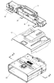
図2を参照して、天板11の下方であって手前側の位置には制御基板などの比較的高温に弱い部品が収納される箱状体の冷却ボックス3が配設されている。そして、この冷却ボックス3の更に下方には遮熱板12と、遮熱板12の下方に加熱庫であるグリル庫22が配設されている。
Referring to FIG. 2, a box-
上記冷却ボックス3は左右方向に長手の直方体形状であり、右端には冷却ボックス3内に空気を取り込むファン31が設けられている。そして、ファン31によって冷却ボックス3内に吸い込まれた空気の一部は途中で前方吹き出し口33から前方に吹き出し、あるいは上方に吹き出すものの、大半は左端に設けた排気口32から吹き出す。このため、冷却ボックス3内では右側から左側への空気流が生じるように構成されている。
The
また、グリル庫22の天井部には透光部である板状の耐熱ガラス5が取り付けられている。
In addition, a plate-shaped heat-
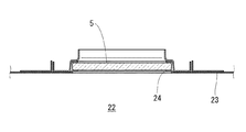
図3を参照して、グリル庫22の天井部23に開口24が形成されており、その開口24を上方から覆うように耐熱ガラス5が取り付けられている。この耐熱ガラス5は、本実施の形態では上方からの光を透光してグリル庫22内を照明するためのものであり、その照明用の光を照射する照明ユニットが、上記冷却ボックス3の底板4に取り付けられている。
With reference to FIG. 3, an
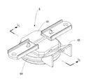
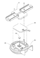
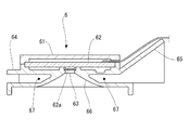
図4から図6を参照して、6は照明ユニットの一例である。この照明ユニット6は基部64と蓋部61とで挟まれた空間内に、下面にチップ状のLED62aが実装されたLED基板62が保持され、LED62aから照射される光を拡散レンズ63で下方に向かって所定の広がりで照射するものである。拡散レンズ63で拡散された光は円錐筒状の導光路66を通る。そして、この導光路66の周囲には導光路66を囲繞するように空気通路67が形成されている。なお、65は空気流をこの空気通路67に導くための導風部である。
4 to 6, 6 is an example of a lighting unit. In the
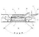
図7を参照して、この照明ユニット6は上記冷却ボックス3の底板4に設けた収納部42内に設置されている。この収納部42は上記耐熱ガラス5の直上に位置するように、底板4の底部41から下方に凹ませて形成されている。従って、この収納部42に照明ユニット6を設置することにより、照明ユニット6から照射された光は耐熱ガラス5を透過してグリル庫22内の被調理物を照明することになる。
Referring to FIG. 7, the
このように、収納部42を下方に凹ませたことにより照明ユニット6がグリル庫22に近づいて、その結果、照明範囲を広くすることができる。但し、照明ユニット6がグリル庫22に近づけば、照明ユニット6はグリル庫22からの熱の影響を受けて高温になりやすくなる。
In this manner, the
そこで、照明ユニット6の空気通路67に空気を流して、主に導光路66を空冷するようにした。この空冷用の空気はファン31によって冷却ボックス3内を右から左方向に流れている空気流Fを利用するが、上述のように、収納部42を下方に凹ませているため、空気流Fが空気通路67内に流れ込みにくくなる。そこで、導風部65で空気流Fを空気通路67へ流れるように案内して、空気通路67に十分な流量の空気が流れるようにした。なお、導風部65が十分に空気流Fをガイドできるように、導風部65の先端を底板4の底部41よりも上方に寸法「d」だけ突出するように設定した。
Therefore, air is flowed through the
なお、本発明は上記した形態に限定されるものではなく、本発明の要旨を逸脱しない範囲内において種々の変更を加えてもかまわない。 In addition, this invention is not limited to an above-described form, You may add a various change in the range which does not deviate from the summary of this invention.
1 ガスコンロ
2 グリル
3 冷却ボックス
4 底板
5 耐熱ガラス
6 照明ユニット
11 天板
12 遮熱板
22 グリル庫
31 ファン
32 排気口
42 収納部
63 拡散レンズ
65 導風部
66 導光路
67 空気通路
DESCRIPTION OF
Claims (4)
Priority Applications (1)
| Application Number | Priority Date | Filing Date | Title |
|---|---|---|---|
| JP2016007626A JP6682135B2 (en) | 2016-01-19 | 2016-01-19 | Cooking device |
Applications Claiming Priority (1)
| Application Number | Priority Date | Filing Date | Title |
|---|---|---|---|
| JP2016007626A JP6682135B2 (en) | 2016-01-19 | 2016-01-19 | Cooking device |
Publications (2)
| Publication Number | Publication Date |
|---|---|
| JP2017129295A true JP2017129295A (en) | 2017-07-27 |
| JP6682135B2 JP6682135B2 (en) | 2020-04-15 |
Family
ID=59395534
Family Applications (1)
| Application Number | Title | Priority Date | Filing Date |
|---|---|---|---|
| JP2016007626A Active JP6682135B2 (en) | 2016-01-19 | 2016-01-19 | Cooking device |
Country Status (1)
| Country | Link |
|---|---|
| JP (1) | JP6682135B2 (en) |
Citations (2)
| Publication number | Priority date | Publication date | Assignee | Title |
|---|---|---|---|---|
| JP2002325691A (en) * | 2001-05-02 | 2002-11-12 | Paloma Ind Ltd | grill |
| WO2012070257A1 (en) * | 2010-11-22 | 2012-05-31 | 株式会社エノア | Oven |
-
2016
- 2016-01-19 JP JP2016007626A patent/JP6682135B2/en active Active
Patent Citations (2)
| Publication number | Priority date | Publication date | Assignee | Title |
|---|---|---|---|---|
| JP2002325691A (en) * | 2001-05-02 | 2002-11-12 | Paloma Ind Ltd | grill |
| WO2012070257A1 (en) * | 2010-11-22 | 2012-05-31 | 株式会社エノア | Oven |
Also Published As
| Publication number | Publication date |
|---|---|
| JP6682135B2 (en) | 2020-04-15 |
Similar Documents
| Publication | Publication Date | Title |
|---|---|---|
| JP6579301B2 (en) | Cooker | |
| KR101949581B1 (en) | Lighting apparatus and cooking appliance therewith | |
| KR102363887B1 (en) | Light emitting door and cooking appliance therewith | |
| JP6508625B2 (en) | Cooker | |
| JP6101858B2 (en) | Cooker | |
| CN107752793A (en) | Domestic oven with Muffle furnace lighting device | |
| CN109477641A (en) | oven | |
| KR101847286B1 (en) | Member for inducing air flow and cooking appliance therewith | |
| EP3267115B1 (en) | Light source module and cooking appliance including the same | |
| JP5762759B2 (en) | Cooking equipment | |
| US20250198627A1 (en) | Cooking apparatus | |
| JP6682135B2 (en) | Cooking device | |
| KR102087974B1 (en) | Light emitting door and cooking appliance therewith | |
| KR20240035304A (en) | Cooking apparatus | |
| CN111426120A (en) | Refrigerator with a door | |
| KR100678778B1 (en) | Oven lamp cooling structure of electric oven | |
| US20250142685A1 (en) | Heating cooker | |
| JP2005241130A (en) | Range hood for ih cooking heater | |
| JP2020176763A (en) | Cooker | |
| JP2010071503A (en) | High-frequency heating device | |
| HK1152370A (en) | A cooking oven with an illumination-equipment and an illumination-equipment for a cavity of cooking oven | |
| JP2014222133A (en) | Cooker | |
| JPS61186724A (en) | High frequency heating device |
Legal Events
| Date | Code | Title | Description |
|---|---|---|---|
| A521 | Request for written amendment filed |
Free format text: JAPANESE INTERMEDIATE CODE: A523 Effective date: 20160212 |
|
| A521 | Request for written amendment filed |
Free format text: JAPANESE INTERMEDIATE CODE: A523 Effective date: 20161028 |
|
| A621 | Written request for application examination |
Free format text: JAPANESE INTERMEDIATE CODE: A621 Effective date: 20180921 |
|
| A977 | Report on retrieval |
Free format text: JAPANESE INTERMEDIATE CODE: A971007 Effective date: 20190830 |
|
| A131 | Notification of reasons for refusal |
Free format text: JAPANESE INTERMEDIATE CODE: A131 Effective date: 20190910 |
|
| A521 | Request for written amendment filed |
Free format text: JAPANESE INTERMEDIATE CODE: A523 Effective date: 20191030 |
|
| TRDD | Decision of grant or rejection written | ||
| A01 | Written decision to grant a patent or to grant a registration (utility model) |
Free format text: JAPANESE INTERMEDIATE CODE: A01 Effective date: 20200324 |
|
| A61 | First payment of annual fees (during grant procedure) |
Free format text: JAPANESE INTERMEDIATE CODE: A61 Effective date: 20200324 |
|
| R150 | Certificate of patent or registration of utility model |
Ref document number: 6682135 Country of ref document: JP Free format text: JAPANESE INTERMEDIATE CODE: R150 |
|
| R250 | Receipt of annual fees |
Free format text: JAPANESE INTERMEDIATE CODE: R250 |
|
| R250 | Receipt of annual fees |
Free format text: JAPANESE INTERMEDIATE CODE: R250 |
|
| R250 | Receipt of annual fees |
Free format text: JAPANESE INTERMEDIATE CODE: R250 |
|
| R250 | Receipt of annual fees |
Free format text: JAPANESE INTERMEDIATE CODE: R250 |