JP2017131902A - Nozzle structure - Google Patents
Nozzle structure Download PDFInfo
- Publication number
- JP2017131902A JP2017131902A JP2016011775A JP2016011775A JP2017131902A JP 2017131902 A JP2017131902 A JP 2017131902A JP 2016011775 A JP2016011775 A JP 2016011775A JP 2016011775 A JP2016011775 A JP 2016011775A JP 2017131902 A JP2017131902 A JP 2017131902A
- Authority
- JP
- Japan
- Prior art keywords
- inner hole
- nozzle structure
- nozzle
- hole sleeve
- refractory
- Prior art date
- Legal status (The legal status is an assumption and is not a legal conclusion. Google has not performed a legal analysis and makes no representation as to the accuracy of the status listed.)
- Granted
Links
Images






Classifications
-
- B—PERFORMING OPERATIONS; TRANSPORTING
- B22—CASTING; POWDER METALLURGY
- B22D—CASTING OF METALS; CASTING OF OTHER SUBSTANCES BY THE SAME PROCESSES OR DEVICES
- B22D41/00—Casting melt-holding vessels, e.g. ladles, tundishes, cups or the like
- B22D41/50—Pouring-nozzles
-
- B—PERFORMING OPERATIONS; TRANSPORTING
- B22—CASTING; POWDER METALLURGY
- B22D—CASTING OF METALS; CASTING OF OTHER SUBSTANCES BY THE SAME PROCESSES OR DEVICES
- B22D41/00—Casting melt-holding vessels, e.g. ladles, tundishes, cups or the like
- B22D41/50—Pouring-nozzles
- B22D41/502—Connection arrangements; Sealing means therefor
-
- B—PERFORMING OPERATIONS; TRANSPORTING
- B22—CASTING; POWDER METALLURGY
- B22D—CASTING OF METALS; CASTING OF OTHER SUBSTANCES BY THE SAME PROCESSES OR DEVICES
- B22D11/00—Continuous casting of metals, i.e. casting in indefinite lengths
- B22D11/10—Supplying or treating molten metal
-
- B—PERFORMING OPERATIONS; TRANSPORTING
- B22—CASTING; POWDER METALLURGY
- B22D—CASTING OF METALS; CASTING OF OTHER SUBSTANCES BY THE SAME PROCESSES OR DEVICES
- B22D41/00—Casting melt-holding vessels, e.g. ladles, tundishes, cups or the like
- B22D41/50—Pouring-nozzles
- B22D41/52—Manufacturing or repairing thereof
- B22D41/54—Manufacturing or repairing thereof characterised by the materials used therefor
Landscapes
- Engineering & Computer Science (AREA)
- Mechanical Engineering (AREA)
- Manufacturing & Machinery (AREA)
- Casting Support Devices, Ladles, And Melt Control Thereby (AREA)
- Continuous Casting (AREA)
Abstract
Description
本発明は溶鋼排出用のノズル構造体に関する。 The present invention relates to a nozzle structure for discharging molten steel.
例えばタンディッシュから溶鋼を排出するための、その溶鋼導入口から鋳型までの溶鋼排出経路としてのノズル構造体は、その溶鋼排出方向(上下方向)に複数に分割した耐火物部材から構成されることがある。これは溶鋼排出における流量制御機能をこのノズル構造体の一部で動的に行うため、又は溶鋼排出経路の部位ごとに異なる損傷等に対し耐用性のバランスを最適化する、若しくは部分的な交換を可能にするためである。 For example, the nozzle structure as a molten steel discharge path from the molten steel inlet to the mold for discharging molten steel from the tundish shall be composed of refractory members divided in multiple in the molten steel discharge direction (vertical direction) There is. This is because the flow control function in molten steel discharge is dynamically performed by a part of this nozzle structure, or the balance of durability is optimized for partial damage of each portion of the molten steel discharge path, or partial replacement This is to make it possible.
このような複数の耐火物部材を組み合わせたノズル構造体では、その耐火物部材間には必然的に目地部が存在することになる。これらの目地部では、スライディングノズル等の摺動を伴う部分に関しては目地材やシール材は使用できないため、いわゆる空目地での接触構造となり、他の摺動がない部分ではモルタルやシール材を設置することが多い。しかし、これらの目地部からは、目地材等の有無による程度の差はあるものの、このノズル構造体の内孔に外気を引き込みやすい(図13参照)。外気を引き込んだ際は内孔へのアルミナ介在物等の付着ないしは閉塞、酸化物の増加、その他の鋼の品質低下等を招来する。 In such a nozzle structure in which a plurality of refractory members are combined, joints inevitably exist between the refractory members. In these joints, joint materials and seal materials cannot be used for sliding parts such as sliding nozzles, so a contact structure with so-called empty joints is provided, and mortar and seal materials are installed in other parts that do not slide. Often to do. However, although there is a difference in the degree depending on the presence or absence of joint material or the like from these joint portions, outside air is easily drawn into the inner hole of the nozzle structure (see FIG. 13). When the outside air is drawn in, it causes adhesion or blockage of alumina inclusions to the inner hole, increase in oxides, and other quality deterioration of the steel.
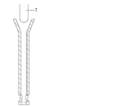
この外気引き込みの対策として、例えば図14に示すように、流量制御機能をノズルではなくその上部に設置したストッパー7で行い、ノズル部分は目地のない一体型の浸漬ノズルとする構造が採用されることもある。しかし、鋼の連続鋳造においては多連鋳化等により鋳造時間が長時間に及ぶ傾向があり、浸漬ノズル等のノズルの一部を交換するために、複数の分割した耐火物部材から構成する構造も依然として必要とされる場合があり、このような場合には目地部が依然として存在することになる。
As a countermeasure against this outside air intake, for example, as shown in FIG. 14, the flow rate control function is not performed by the nozzle but by the
この目地部に関する外気引き込みの対策として、特許文献1には、「鋳造用ノズル耐火物と該耐火物の外周に配置されたケースとの間に形成された隙間に、前記耐火物の外周または内周の少なくとも一部を覆うように金属パイプを配置し、該金属パイプに複数のガス吹き出し孔またはスリットを設け、金属パイプの少なくとも一端よりガスを導入して、耐火物の周囲近傍をガスシールすることを特徴とする鋳造用ノズル。」が開示されている。
As a countermeasure against the outside air drawing in regarding the joint part,
前記の特許文献1では、ガス(不活性ガス)を導入してガスシールするので、外気すなわち溶鋼にとって特に有害な酸素を引き込むリスクは減少させることができるが、ガス(不活性ガス)は依然として引き込む。ガス(不活性ガス)を引き込んだ場合は溶鋼や耐火物の酸化に伴う諸問題は減少するものの、鋼中にピンホール等の品質不良を招来する危険性は残る。
In
本発明が解決しようとする課題は、複数の耐火物部材から構成されて目地部が存在する溶鋼排出用のノズル構造体において、そのシール性を向上させることにある。 The problem to be solved by the present invention is to improve the sealing performance of a nozzle structure for discharging molten steel which is composed of a plurality of refractory members and has joint portions.
本発明は次の1〜7のノズル構造体を提供する。
1.溶鋼排出経路を上下方向に分割して接合する目地部を一又は複数箇所に備えた溶鋼排出用のノズル構造体であって、当該ノズル構造体の内孔面に、耐火物から成る内孔スリーブが前記目地部の少なくとも一を上下方向に跨ぐように設置されている、ノズル構造体。
2.前記内孔スリーブは接着材を介して前記内孔面に設置されている、前記1に記載のノズル構造体。
3.前記内孔スリーブの内孔側の上端部は、曲面又は傾斜面である、前記1又は2に記載のノズル構造体。
4.前記一又は複数の目地部に対応する水平位置の前記内孔スリーブの外周に、一又は複数の非連続の凹部若しくは連続した溝部を設置した、前記1から前記3のいずれかに記載のノズル構造体。
5.前記一又は複数の非連続の凹部若しくは連続した溝部は、前記目地部から下方のノズルの摺動方向又は解体除去のための加圧方向の前後のいずれか若しくは両方の面に相対的に多く配置した、前記4に記載のノズル構造体。
6.前記内孔スリーブを成す耐火物はノズル構造体本体の耐火物よりも難付着性が高い、前記1から前記5のいずれかに記載のノズル構造体。
7.前記内孔スリーブは、CaO成分を約15質量%以上、残部にMgOを含有し、CaO/MgO質量比が0.1以上1.5以下の耐火物から成る、前記6に記載のノズル構造体。
The present invention provides the following nozzle structures 1-7.
1. A nozzle structure for discharging molten steel provided with one or a plurality of joints for dividing and joining a molten steel discharge path in the vertical direction, and an inner hole sleeve made of a refractory material on the inner hole surface of the nozzle structure The nozzle structure is installed so as to straddle at least one of the joints in the vertical direction.
2. 2. The nozzle structure according to 1, wherein the inner hole sleeve is installed on the inner hole surface via an adhesive.
3. 3. The nozzle structure according to 1 or 2, wherein an upper end portion on the inner hole side of the inner hole sleeve is a curved surface or an inclined surface.
4). 4. The nozzle structure according to any one of 1 to 3, wherein one or a plurality of non-continuous concave portions or continuous groove portions are provided on an outer periphery of the inner sleeve at a horizontal position corresponding to the one or a plurality of joint portions. body.
5. The one or a plurality of non-continuous concave portions or continuous groove portions are relatively disposed on either or both of the sliding direction of the nozzle below from the joint portion or the front and rear surfaces in the pressurizing direction for dismantling removal. The nozzle structure according to 4 above.
6). The nozzle structure according to any one of 1 to 5, wherein the refractory forming the inner hole sleeve has higher adhesion than the refractory of the nozzle structure body.
7). 7. The nozzle structure according to 6, wherein the inner hole sleeve is made of a refractory having a CaO component of about 15% by mass or more, the remainder containing MgO, and a CaO / MgO mass ratio of 0.1 to 1.5. .
本発明によれば、ノズル構造体の内孔面に、目地部の少なくとも一を上下方向に跨ぐように内孔スリーブを設置したことで、ノズル構造体のシール性が向上する。そして、全ての目地部を上下方向に跨ぐように内孔スリーブを設置すれば、目地部のない一体的な構造のノズルと同程度のシール性を得ることができる。 According to the present invention, the sealing performance of the nozzle structure is improved by installing the inner hole sleeve on the inner hole surface of the nozzle structure so as to straddle at least one of the joint portions in the vertical direction. And if an inner-hole sleeve is installed so that all the joint parts may be straddled to an up-down direction, the sealing performance comparable as the nozzle of the integral structure without a joint part can be acquired.
また、内孔スリーブの外周に凹部や溝部を設けることで、ノズル構造体の特定の場所で折って取り外す等の場合にも、シール性を害することなく安全に、また所定の部位で正確に分離することができ、その後に交換品を設置する場合にも、接合面での凹凸等が小さく接合の精度を高く維持して、しかも容易に取り外しや取り付け作業を行うことができる。 In addition, by providing a recess or groove on the outer periphery of the inner hole sleeve, it can be safely and accurately separated at a predetermined location without damaging the sealing performance even when it is folded and removed at a specific location of the nozzle structure. Even when a replacement product is installed after that, the unevenness on the joining surface is small and the joining accuracy can be kept high, and the removal and attachment operations can be easily performed.
さらには、内孔面の損傷やアルミナ介在物の付着等に対する特性が異なる、様々な材質・物性を備える耐火物を自由にかつ容易に選択して適用することが可能となる。ひいては、鋼の品質低下を抑制することができる。 Furthermore, it becomes possible to freely and easily select and apply a refractory material having various materials and physical properties that have different characteristics with respect to damage to the inner hole surface and adhesion of alumina inclusions. As a result, the quality deterioration of steel can be suppressed.
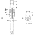
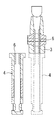
本発明のノズル構造体の典型的かつ分割数すなわち目地数が最も多い形態は、上ノズル、3枚構成のスライディングノズルプレート(上プレート、中プレート、下プレート)、中間ノズル、下ノズル、浸漬ノズル等の複数の耐火物部材から構成される場合である。しかし、この形態に限定する必要はなく、前記各耐火物のいずれか2以上の組み合わせによる形態のいずれでもよい。例えば、図1(a)は、上ノズル1、上プレート2a、中プレート2b、下プレート2c、下ノズル3及び浸漬ノズル4から構成される例、図1(b)は、上ノズル1及び浸漬ノズル4から構成される例である。すなわち、本発明のノズル構造体は、内孔5を有する溶鋼排出経路を上下方向に分割して接合する目地部を一又は複数箇所に備えた溶鋼排出用のノズル構造体である。そして、本発明のノズル構造体には、当該ノズル構造体の内孔面に、耐火物から成る内孔スリーブ6が前記目地部の少なくとも一を上下方向に跨ぐように設置されている。
The typical structure of the nozzle structure of the present invention having the largest number of divisions, that is, the number of joints, is an upper nozzle, a three-sliding sliding plate (upper plate, middle plate, lower plate), intermediate nozzle, lower nozzle, and immersion nozzle. It is a case where it comprises a plurality of refractory members such as. However, it is not necessary to limit to this form, and any of the above-described combinations of two or more refractories may be used. For example, FIG. 1A shows an example composed of an
この内孔スリーブ6は、シール性をより確実にし、さらには高めるためには、図1(a)及び図1(b)に示すように、上下方向に分割しないで一体的な構造とし、全ての目地部を上下方向に跨ぐように設置することが最も好ましい。ただし、内孔スリーブは、目地部の少なくとも一を上下方向に跨ぐように設置すれば、シール性の向上に寄与する。
This
また、内孔スリーブ6は、図2に示すように上下方向に複数個に分割することも可能であるが、このような分割構造にする場合は、その分割部分すなわち目地部分A1は、ノズル構造体本体である溶鋼排出経路の分割部分すなわち目地部B1,B2と一致しないようにする必要がある。言い換えると、本発明において内孔スリーブが目地部を上下方向に跨ぐとは、当該目地部に対応する内孔スリーブの上下方向の水平位置では内孔スリーブが上下方向に分割されていない連続体であることを意味する。なお、ノズル構造体外部からの外気(ガス)の引き込みを効果的に抑制するためには、内孔スリーブ6の目地部分A1とノズル構造体本体の目地部B1,B2との上下方向の間隔(長さ)Lは、経験上、内孔スリーブ6の厚さ以上であることが好ましい。
Further, the
また、内孔スリーブを設置する場合、ノズル構造体を構成する各ノズル(耐火物部材)の水平方向の位置が所定の位置に正確に存在することが必要である。このノズルごとの相対的な水平位置は、そのセット装置等によって決定されるが、例えば図3に示すように、相対的に下方に設置されるノズルの内孔面上端部には、上方のノズルと下方のノズルとの水平方向の相対的な精度以上の長さの切り欠き、すなわち内孔側に向けて下方に傾斜又は曲面を有する部分を設けておくことが好ましい。これにより、ノズル構造体の内孔に上方から内孔スリーブを装入する際にスムーズに設置することができる。 Further, when the inner hole sleeve is installed, it is necessary that the position in the horizontal direction of each nozzle (refractory member) constituting the nozzle structure is accurately present at a predetermined position. The relative horizontal position of each nozzle is determined by the setting device or the like. For example, as shown in FIG. It is preferable to provide a notch having a length greater than the relative accuracy in the horizontal direction between the nozzle and the lower nozzle, that is, a portion having an inclined or curved surface downward toward the inner hole side. Accordingly, the inner hole sleeve can be installed smoothly when inserted into the inner hole of the nozzle structure from above.
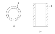
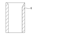
内孔スリーブ6の形状は、図4に示すように典型的には円筒状であるが、その内孔側の上端部は、図5に示すように曲面又は傾斜面として、できる限り溶鋼の排出方向に対して小さな角度又はなだらかに漸増する形状にすることが好ましい。溶鋼の排出方向に対して例えば水平方向の面のように大きな角度を有する段差構造とすると、その部分で溶鋼流が大きく乱れ、介在物の付着、内孔スリーブの局部損傷等を招来するおそれがある。
The shape of the
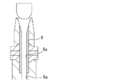
また、内孔スリーブ6の内孔面6aは、図6に示すようにノズル構造体の内孔面5aと面一にすることができる。これにより内孔スリーブ6の上端部及び下端部における内孔面の段差部をなくすことができる。
Further, the
図7に示すように内孔スリーブ6の下端部のみで内孔面の段差部をなくすようにすることもできる。この下端部での段差部もその部分で渦流等の溶鋼流の乱れを生じる基点となる場合がある。このような場合に内孔スリーブ6の下端部のみで内孔面の段差部をなくすだけでも、溶鋼流の乱れが生じるのを抑制できる。また、内孔スリーブ6の下端部をノズル構造体の内孔面5aと同じ径(面一)にすることで、内孔スリーブ6の下方への落下やズレを防止することもできる。なお、内孔スリーブ6の下方への落下やズレを防止するために、内孔スリーブ6の下端部直下付近のノズル構造体の内孔面5aに突状部や傾斜部を備えてもよい。
As shown in FIG. 7, the step portion of the inner hole surface can be eliminated only by the lower end portion of the
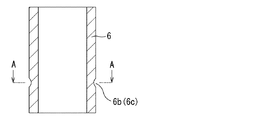
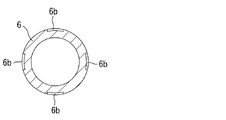
内孔スリーブ6の外周には、図8に示すように一又は複数の非連続の凹部6b又は連続した溝部6cを設けることができる。例えば、図9の例では内孔スリーブ6の外周の一部に凹部6bを分割して4箇所に設け、図10の例では内孔スリーブ6の外周の一部に円周方向に連続する溝部6cを1本設けている。これらの凹部6b又は溝部6cは、ノズル構造体本体の目地部に対応する水平位置の内孔スリーブ6の外周に設ける。その理由は次のとおりである。まず、緊急時又はノズル構造体の耐火物部材(部品)の一部を交換する等のために、例えば図11に示すように浸漬ノズル4をその上端の接合面の位置で取り外す場合、内孔スリーブ6が内側に設置されていると内孔スリーブ6が不規則な位置で複雑な形態で破壊する可能性があり、また破壊自体がし難くなる可能性がある。そこで、前述のようにノズル構造体本体の目地部に対応する水平位置(図11の場合は浸漬ノズル4の上端部に相当する水平位置)の内孔スリーブ6の外周に凹部6b又は溝部6cを設けることで、内孔スリーブ6を破壊しやすくし、さらには希望する所定の位置から高い精度で破壊することができる(図12参照)。
As shown in FIG. 8, one or a plurality of
なお、前記の「緊急時」とはストッパー制御に異状を生じてストッパー以外の場所でノズルを閉じて溶鋼流を停止する場合、例えばノズル構造体の一部がスライド可能になっていて、そのスライドにより内孔スリーブをそのスライド部で折って分離する場合等が挙げられる。また、前記の「ノズル構造体の耐火物部材(部品)の一部を交換する」とは、例えば浸漬ノズルを、水平方向にスライド、又は斜め下方に機械的に荷重を加えて内孔スリーブを破壊して浸漬ノズルを取り外し、その後再度他の浸漬ノズルを水平方向にスライドし、又は下方から装着する場合が挙げられる。これらのいずれの場合も、内孔スリーブは容易かつ凹凸の少ない高精度で破壊されることが好ましい。 In the case of “emergency”, when the stopper control is abnormal and the nozzle is closed at a place other than the stopper to stop the molten steel flow, for example, a part of the nozzle structure can be slid, For example, the inner hole sleeve is folded and separated at its slide portion. In addition, the above-mentioned “replace a part of the refractory member (part) of the nozzle structure” means, for example, that the immersion nozzle is slid horizontally or the inner sleeve is mechanically applied obliquely downward. The case where it is broken and the immersion nozzle is removed, and then another immersion nozzle is slid in the horizontal direction again or mounted from below. In any of these cases, it is preferable that the inner-hole sleeve is easily broken with high accuracy and less unevenness.
これら凹部6b又は溝部6cは、前記ノズル構造体本体の目地部から下方のノズルの摺動方向又は解体除去のための加圧方向の前後のいずれか又は両方の面に相対的に多く配置することが好ましい。摺動方向又は加圧方向の外周が応力の基点になるからである。
A relatively large number of these
また、内孔スリーブ6はモルタル等の接着材を介してノズル構造体の内孔面に設置されていることが好ましい。内孔スリーブ6を設置することでガスを引き込む危険性は軽減するが、接着材を使用しない場合はガスが通過しない程度に接合面の面精度を高める等の工夫が必要になる。これはコスト面からも現実的ではない。
The
接着剤(モルタル)はノズル構造体の組成に応じて、それらに溶融等を生じさせない材質等、一般的にノズル構造体用に使用されている材質であれば特に制限なく使用できる。なお、本発明者らの経験上の知見では、例えば見掛け気孔率が、約1000℃〜1400℃の程度の熱処理後で概ね30%以下程度のモルタルであれば、ガス等が内孔まで通過することはない。 The adhesive (mortar) can be used without particular limitation as long as it is a material generally used for the nozzle structure, such as a material that does not cause melting or the like according to the composition of the nozzle structure. According to the experience of the present inventors, for example, if the apparent porosity is a mortar of about 30% or less after heat treatment of about 1000 ° C. to 1400 ° C., gas or the like passes to the inner hole. There is nothing.
一方、内孔スリーブ6の内孔面におけるアルミナ等の非金属介在物や地金の付着ないしは成長は、鋳造中の溶鋼流の乱れや鋳造速度低下等の操業面での、鋼の品質や生産性に悪影響を及ぼす。さらには浸漬ノズルを始めとするノズルの解体又は取り外しが困難になる。そこで、内孔スリーブ6を成す耐火物はノズル構造体本体の耐火物よりも難付着性が高い材質にすることで、内孔面へのアルミナ等介在物の付着を軽減することができ、さらには地金の付着ないしは成長を軽減することができる。難付着性が高い材質としては、例えばCaO成分を約15質量%以上、残部にMgO、ZrO2、炭素等の耐火成分を含み、CaO/MgO質量比が0.1以上1.5以下である耐火物、その他の溶鋼や溶鋼中成分と反応して表面を滑らかにする化学組成を含有・調整した材質、又は表面の平滑度を高めた材質等を挙げることができる。
On the other hand, the adhesion or growth of non-metallic inclusions such as alumina and metal on the inner hole surface of the
なお、以上の実施形態では、タンディッシュから鋳型へ溶鋼を排出するためのノズル構造体を例に説明したが、本発明の適用範囲はタンディッシュ用に限定されず、溶鋼排出用の他のノズル構造体に適用することもできる。 In the above embodiment, the nozzle structure for discharging molten steel from the tundish to the mold has been described as an example. However, the scope of application of the present invention is not limited to tundish, and other nozzles for discharging molten steel It can also be applied to structures.
1 上ノズル
2a 上プレート
2b 中プレート
2c 下プレート
3 下ノズル
4 浸漬ノズル
5 内孔
5a 内孔面
6 内孔スリーブ
6a 内孔面
6b 凹部
6c 溝部
7 ストッパー
DESCRIPTION OF
Claims (7)
Priority Applications (10)
| Application Number | Priority Date | Filing Date | Title |
|---|---|---|---|
| JP2016011775A JP6663230B2 (en) | 2016-01-25 | 2016-01-25 | Nozzle structure |
| US16/070,934 US10799950B2 (en) | 2016-01-25 | 2016-11-09 | Nozzle structure |
| PCT/JP2016/083186 WO2017130517A1 (en) | 2016-01-25 | 2016-11-09 | Nozzle structure |
| CN201680077658.XA CN108778564B (en) | 2016-01-25 | 2016-11-09 | Nozzle structure |
| BR112018015149-1A BR112018015149B1 (en) | 2016-01-25 | 2016-11-09 | NOZZLE STRUCTURE TO DISCHARGE CAST STEEL |
| AU2016390149A AU2016390149B2 (en) | 2016-01-25 | 2016-11-09 | Nozzle structure |
| CA3011206A CA3011206C (en) | 2016-01-25 | 2016-11-09 | Nozzle structure |
| EP16888102.7A EP3409399B1 (en) | 2016-01-25 | 2016-11-09 | Nozzle structure |
| KR1020187018451A KR102132983B1 (en) | 2016-01-25 | 2016-11-09 | Nozzle structure |
| TW105139086A TWI615220B (en) | 2016-01-25 | 2016-11-28 | Nozzle structure |
Applications Claiming Priority (1)
| Application Number | Priority Date | Filing Date | Title |
|---|---|---|---|
| JP2016011775A JP6663230B2 (en) | 2016-01-25 | 2016-01-25 | Nozzle structure |
Publications (2)
| Publication Number | Publication Date |
|---|---|
| JP2017131902A true JP2017131902A (en) | 2017-08-03 |
| JP6663230B2 JP6663230B2 (en) | 2020-03-11 |
Family
ID=59397609
Family Applications (1)
| Application Number | Title | Priority Date | Filing Date |
|---|---|---|---|
| JP2016011775A Expired - Fee Related JP6663230B2 (en) | 2016-01-25 | 2016-01-25 | Nozzle structure |
Country Status (10)
| Country | Link |
|---|---|
| US (1) | US10799950B2 (en) |
| EP (1) | EP3409399B1 (en) |
| JP (1) | JP6663230B2 (en) |
| KR (1) | KR102132983B1 (en) |
| CN (1) | CN108778564B (en) |
| AU (1) | AU2016390149B2 (en) |
| BR (1) | BR112018015149B1 (en) |
| CA (1) | CA3011206C (en) |
| TW (1) | TWI615220B (en) |
| WO (1) | WO2017130517A1 (en) |
Families Citing this family (3)
| Publication number | Priority date | Publication date | Assignee | Title |
|---|---|---|---|---|
| JP7182496B2 (en) * | 2019-03-12 | 2022-12-02 | 黒崎播磨株式会社 | Nozzle and structure of nozzle and stopper |
| JP2021049564A (en) * | 2019-09-26 | 2021-04-01 | 黒崎播磨株式会社 | Tundish upper nozzle structure and method of continuous casting |
| EP3827912B1 (en) * | 2019-11-26 | 2022-03-30 | Refractory Intellectual Property GmbH & Co. KG | An exchangeable nozzle for a nozzle changer system, a method for manufacturing such a nozzle, a nozzle changer system comprising such a nozzle and a tundish comprising such a nozzle changer system |
Citations (7)
| Publication number | Priority date | Publication date | Assignee | Title |
|---|---|---|---|---|
| JPS5619970A (en) * | 1979-07-27 | 1981-02-25 | Nippon Steel Corp | Repairing method of sliding nozzle |
| JPH0751839A (en) * | 1993-07-26 | 1995-02-28 | Magneco Metrel Inc | Yudama nozzle assembly block |
| JPH09220649A (en) * | 1996-02-09 | 1997-08-26 | Akechi Ceramics Kk | Long nozzle for continuous casting |
| JPH115145A (en) * | 1997-04-22 | 1999-01-12 | Toshiba Ceramics Co Ltd | Integrated immersion nozzle and method for manufacturing the same |
| JP2002153970A (en) * | 2000-11-22 | 2002-05-28 | Shinagawa Refract Co Ltd | Multi-layer structural molten metal pouring nozzle |
| WO2003086684A1 (en) * | 2002-04-02 | 2003-10-23 | Krosakiharima Corporation | Binding structure of refractory sleeve for inner hole of nozzle for continuous casting |
| JP2010036229A (en) * | 2008-08-06 | 2010-02-18 | Kurosaki Harima Corp | Nozzle for continuous casting |
Family Cites Families (15)
| Publication number | Priority date | Publication date | Assignee | Title |
|---|---|---|---|---|
| US4165026A (en) * | 1971-12-07 | 1979-08-21 | Foseco Trading A.G. | Tundish with expendable lining and easily removable nozzle |
| JPS595489Y2 (en) * | 1980-11-12 | 1984-02-18 | 川崎製鉄株式会社 | Nozzle for molten metal injection |
| JPS57134252A (en) * | 1981-02-10 | 1982-08-19 | Nippon Steel Corp | Nozzle for continuous casting |
| US5723055A (en) * | 1995-10-10 | 1998-03-03 | Vesuvius Crucible Company | Nozzle assembly having inert gas distributor |
| DE19818028C2 (en) | 1997-04-22 | 2001-11-29 | Toshiba Ceramics Co | Integrated immersion nozzle and process for its manufacture |
| JPH11104814A (en) | 1997-10-01 | 1999-04-20 | Toshiba Ceramics Co Ltd | Nozzle for casting |
| JP2002096145A (en) * | 2000-09-18 | 2002-04-02 | Nippon Steel Corp | Nozzle for continuous casting and continuous casting method of steel using the nozzle |
| WO2005018851A1 (en) * | 2003-08-22 | 2005-03-03 | Krosakiharima Corporation | Immersion nozzle for continuous casting of steel and meethod for continuous casting of steel using the immersion nozzle |
| JP4512560B2 (en) * | 2006-03-03 | 2010-07-28 | 新日本製鐵株式会社 | Continuous casting nozzle |
| WO2010013686A1 (en) | 2008-07-28 | 2010-02-04 | 黒崎播磨株式会社 | Refractory for nozzle used in continuous casting and nozzle for continuous casting |
| JP4695701B2 (en) * | 2009-07-24 | 2011-06-08 | 黒崎播磨株式会社 | Molten metal discharge nozzle |
| JP2014512277A (en) * | 2011-04-29 | 2014-05-22 | ベスビウス クルーシブル カンパニー | Refractory elements, assemblies and tundish for transporting molten metal |
| WO2013081113A1 (en) * | 2011-12-01 | 2013-06-06 | 黒崎播磨株式会社 | Refractory and nozzle for casting |
| AU2014239412B2 (en) * | 2013-03-21 | 2016-05-26 | Krosakiharima Corporation | Refractory and nozzle for casting |
| AR099467A1 (en) * | 2014-02-19 | 2016-07-27 | Vesuvius Group Sa | COAT SPOON COAT FOR METAL COAT, COUPLING ASSEMBLY SET TO COUPLING SUCH COVER SPOON COVERING TO A SPOON, METAL COATING INSTALLATION AND COUPLING PROCESS |
-
2016
- 2016-01-25 JP JP2016011775A patent/JP6663230B2/en not_active Expired - Fee Related
- 2016-11-09 KR KR1020187018451A patent/KR102132983B1/en not_active Expired - Fee Related
- 2016-11-09 BR BR112018015149-1A patent/BR112018015149B1/en not_active IP Right Cessation
- 2016-11-09 CA CA3011206A patent/CA3011206C/en active Active
- 2016-11-09 AU AU2016390149A patent/AU2016390149B2/en not_active Ceased
- 2016-11-09 CN CN201680077658.XA patent/CN108778564B/en not_active Expired - Fee Related
- 2016-11-09 WO PCT/JP2016/083186 patent/WO2017130517A1/en not_active Ceased
- 2016-11-09 EP EP16888102.7A patent/EP3409399B1/en not_active Not-in-force
- 2016-11-09 US US16/070,934 patent/US10799950B2/en not_active Expired - Fee Related
- 2016-11-28 TW TW105139086A patent/TWI615220B/en not_active IP Right Cessation
Patent Citations (7)
| Publication number | Priority date | Publication date | Assignee | Title |
|---|---|---|---|---|
| JPS5619970A (en) * | 1979-07-27 | 1981-02-25 | Nippon Steel Corp | Repairing method of sliding nozzle |
| JPH0751839A (en) * | 1993-07-26 | 1995-02-28 | Magneco Metrel Inc | Yudama nozzle assembly block |
| JPH09220649A (en) * | 1996-02-09 | 1997-08-26 | Akechi Ceramics Kk | Long nozzle for continuous casting |
| JPH115145A (en) * | 1997-04-22 | 1999-01-12 | Toshiba Ceramics Co Ltd | Integrated immersion nozzle and method for manufacturing the same |
| JP2002153970A (en) * | 2000-11-22 | 2002-05-28 | Shinagawa Refract Co Ltd | Multi-layer structural molten metal pouring nozzle |
| WO2003086684A1 (en) * | 2002-04-02 | 2003-10-23 | Krosakiharima Corporation | Binding structure of refractory sleeve for inner hole of nozzle for continuous casting |
| JP2010036229A (en) * | 2008-08-06 | 2010-02-18 | Kurosaki Harima Corp | Nozzle for continuous casting |
Also Published As
| Publication number | Publication date |
|---|---|
| EP3409399A1 (en) | 2018-12-05 |
| EP3409399B1 (en) | 2021-01-06 |
| CN108778564B (en) | 2020-12-29 |
| TW201731611A (en) | 2017-09-16 |
| TWI615220B (en) | 2018-02-21 |
| CA3011206C (en) | 2020-05-05 |
| EP3409399A4 (en) | 2019-08-14 |
| US20190030599A1 (en) | 2019-01-31 |
| AU2016390149A1 (en) | 2018-07-26 |
| WO2017130517A1 (en) | 2017-08-03 |
| BR112018015149B1 (en) | 2021-09-08 |
| KR102132983B1 (en) | 2020-07-10 |
| CN108778564A (en) | 2018-11-09 |
| US10799950B2 (en) | 2020-10-13 |
| AU2016390149B2 (en) | 2020-03-19 |
| JP6663230B2 (en) | 2020-03-11 |
| KR20180088871A (en) | 2018-08-07 |
| CA3011206A1 (en) | 2017-08-03 |
| BR112018015149A2 (en) | 2018-12-18 |
Similar Documents
| Publication | Publication Date | Title |
|---|---|---|
| WO2017130517A1 (en) | Nozzle structure | |
| JP5958566B2 (en) | Slab continuous casting equipment | |
| JP5755259B2 (en) | Long nozzle for continuous casting | |
| JP5643583B2 (en) | Gas blown refractory | |
| WO2024106221A1 (en) | Continuous casting nozzle | |
| JP6630157B2 (en) | Immersion nozzle | |
| US11235384B2 (en) | Sliding nozzle | |
| CN116745047B (en) | Dip nozzles for continuous casting | |
| WO2024048381A1 (en) | Immersion nozzle | |
| JP2019524450A (en) | Tundish funnel | |
| JP5697193B2 (en) | Nozzle for gas injection | |
| JP5360334B1 (en) | Immersion nozzle for continuous casting and continuous casting method using the same | |
| JP5705519B2 (en) | Reusing sliding gate plate and sliding nozzle | |
| JP6430844B2 (en) | Bubbling plate | |
| WO2012074086A1 (en) | Sliding nozzle plate and sliding nozzle device using same | |
| WO2018235801A1 (en) | Casting nozzle | |
| JP5161814B2 (en) | Immersion nozzle for continuous casting | |
| JP2015174806A (en) | Molten glass flow displacement member | |
| JP2016017206A (en) | Steel outlet sleeve |
Legal Events
| Date | Code | Title | Description |
|---|---|---|---|
| A621 | Written request for application examination |
Free format text: JAPANESE INTERMEDIATE CODE: A621 Effective date: 20181101 |
|
| A131 | Notification of reasons for refusal |
Free format text: JAPANESE INTERMEDIATE CODE: A131 Effective date: 20190702 |
|
| A521 | Request for written amendment filed |
Free format text: JAPANESE INTERMEDIATE CODE: A523 Effective date: 20190807 |
|
| A131 | Notification of reasons for refusal |
Free format text: JAPANESE INTERMEDIATE CODE: A131 Effective date: 20190917 |
|
| A521 | Request for written amendment filed |
Free format text: JAPANESE INTERMEDIATE CODE: A523 Effective date: 20191018 |
|
| A02 | Decision of refusal |
Free format text: JAPANESE INTERMEDIATE CODE: A02 Effective date: 20191126 |
|
| A521 | Request for written amendment filed |
Free format text: JAPANESE INTERMEDIATE CODE: A523 Effective date: 20200110 |
|
| A911 | Transfer to examiner for re-examination before appeal (zenchi) |
Free format text: JAPANESE INTERMEDIATE CODE: A911 Effective date: 20200121 |
|
| TRDD | Decision of grant or rejection written | ||
| A01 | Written decision to grant a patent or to grant a registration (utility model) |
Free format text: JAPANESE INTERMEDIATE CODE: A01 Effective date: 20200212 |
|
| A61 | First payment of annual fees (during grant procedure) |
Free format text: JAPANESE INTERMEDIATE CODE: A61 Effective date: 20200214 |
|
| R150 | Certificate of patent or registration of utility model |
Ref document number: 6663230 Country of ref document: JP Free format text: JAPANESE INTERMEDIATE CODE: R150 |
|
| LAPS | Cancellation because of no payment of annual fees |