JP2017132017A - Turntable swivel end detection device - Google Patents
Turntable swivel end detection device Download PDFInfo
- Publication number
- JP2017132017A JP2017132017A JP2016016038A JP2016016038A JP2017132017A JP 2017132017 A JP2017132017 A JP 2017132017A JP 2016016038 A JP2016016038 A JP 2016016038A JP 2016016038 A JP2016016038 A JP 2016016038A JP 2017132017 A JP2017132017 A JP 2017132017A
- Authority
- JP
- Japan
- Prior art keywords
- turntable
- air
- turning end
- turning
- air outlet
- Prior art date
- Legal status (The legal status is an assumption and is not a legal conclusion. Google has not performed a legal analysis and makes no representation as to the accuracy of the status listed.)
- Pending
Links
Images


Landscapes
- Machine Tool Sensing Apparatuses (AREA)
- Machine Tool Units (AREA)
Abstract
【課題】簡単な構成で容易にターンテーブルの旋回位置がどちらの旋回端に位置しているかを検知し、製造コストを低減させることができるターンテーブルの旋回端検知装置を提供する。【解決手段】旋回端検知装置は、左旋回端と右旋回端との間で往復旋回するターンテーブル10に設けられ単一のブロック12の外側面に開口する単一のエア吹き出し口20と、エア吹き出し口20にエアを供給するエア回路22と、エア回路22のエアの圧力を検出する単一のエア圧力センサ24と、ターンテーブル10の旋回位置が左旋回端にあるとき、エア吹き出し口20を第1開度に絞るように配設された第1絞り部材26と、ターンテーブル10の旋回位置が右旋回端にあるとき、エア吹き出し口20を第1開度とは異なる第2開度に絞るように配設された第2絞り部材28とを備えている。【選択図】図1Provided is a turntable turning end detection device that can easily detect which turn end the turning position of a turntable is located with a simple configuration and reduce the manufacturing cost. A turning end detection device is provided in a turntable that reciprocally turns between a left turning end and a right turning end, and a single air outlet 20 that opens to the outer surface of a single block 12. An air circuit 22 for supplying air to the air outlet 20, a single air pressure sensor 24 for detecting the air pressure of the air circuit 22, and an air outlet when the turning position of the turntable 10 is at the left turning end. When the turning position of the first throttle member 26 and the turntable 10 arranged to restrict the opening 20 to the first opening and the turntable 10 is at the right turning end, the air outlet 20 is different from the first opening. And a second throttle member 28 arranged to be throttled to two openings. [Selection] Figure 1
Description
本発明は、ターンテーブルの旋回端検知装置に関し、特に、一方への旋回端である第1旋回端と他方の旋回端である第2旋回端との間で回動されるターンテーブルの旋回位置が、前記第1及び第2旋回端にあることを検知するターンテーブルの旋回端検知装置に関する。 The present invention relates to a turntable turning end detection device, and in particular, a turntable turning position that is turned between a first turning end that is a turning end to one side and a second turning end that is the other turning end. The present invention relates to a turntable detecting device for a turntable that detects that the first and second turning ends are present.
ターンテーブルに関する従来の技術として、たとえば特許文献1が知られている。特許文献1には、シリンダのピストンの延伸・収縮により半回転・半逆回転させる半回転往復テーブル装置が開示されている。そして、特許文献1には、半回転・半逆回転した(旋回端に旋回した)ターンテーブルの回転力を減衰させて停止させるために、ターンテーブルにストッパを設け、両旋回端に緩衝器をそれぞれ配置することが記載されている(0036)。さらに、特許文献1には、その従来の技術として、シリンダのピストンロッドの先端がどの位置にあるかを検出するために、第1ポジションP1(一方の旋回端)、センタポジションPC(両旋回端の中間位置)、及び第2ポジションP2(他方の旋回端)に第1リミットスイッチL1、センタリミットスイッチLC、及び第2リミットスイッチL2をそれぞれ配置することが記載されている。すなわち、特許文献1では、ターンテーブルの旋回位置がどちらかの旋回端にあることを検知するために、第1リミットスイッチL1と第2リミットスイッチL2との2つのリミットスイッチを配置していた。 For example, Patent Document 1 is known as a conventional technique related to a turntable. Patent Document 1 discloses a half-rotation reciprocating table device that performs half-rotation and half-reverse rotation by extending and contracting a piston of a cylinder. And in patent document 1, in order to attenuate and stop the rotational force of the turntable which carried out half rotation and half reverse rotation (turned to the turning end), a stopper was provided in the turntable, and a shock absorber was installed at both turning ends. Each arrangement is described (0036). Further, in Patent Document 1, as the prior art, in order to detect the position of the tip of the piston rod of the cylinder, the first position P1 (one turning end), the center position PC (both turning ends) The first limit switch L1, the center limit switch LC, and the second limit switch L2 are respectively disposed at the intermediate position) and the second position P2 (the other turning end). That is, in Patent Document 1, two limit switches, the first limit switch L1 and the second limit switch L2, are arranged in order to detect that the turning position of the turntable is at one of the turning ends.
また、ターンテーブルの旋回端検知装置の従来の技術として、図7に示したものが知られている。図7に示したターンテーブル10’は、一方への旋回端である第1旋回端(以下、左旋回端という)と他方の旋回端である第2旋回端(以下、右旋回端という)との間で往復回動されるもので、ターンテーブル10’に設けられた単一のブロック12’と、ターンテーブル10’が左旋回端にあるときにブロック12’が当接されるストッパ14’と、ターンテーブル10’が右旋回端にあるときにブロック12’が当接されるストッパ16’とを備えている。このようなターンテーブル10’は、たとえばワークを載置してクーラント(液体)を供給しながら切削加工し、また、切削加工を終えたワークの姿勢や位置を変更するなどのために用いることができる。そして、ターンテーブル10’は、周囲にクーラントが飛散するのを防ぐため、一般に切削加工設備の開閉扉を有する壁などにより構成された空間内に配置される。そのため、ターンテーブル10’の旋回位置が旋回端にあるかどうか、そして、旋回端にある場合に左旋回端と右旋回端のどちらにあるのかを目視で確認するのは困難である。しかしながら、切削加工の開始や切削加工を行うワークのターンテーブル10’上への搬入あるいは切削加工後のワークのターンテーブル10’上からの搬出の開始を判断するなどのために、ターンテーブル10’の旋回位置が左旋回端または右旋回端のいずれにあるかを検知する必要がある。そのため、ターンテーブル10’には、旋回端検知装置が設けられている。図7に示した旋回端検知装置は、各ストッパ14’、16’のブロック12’が当接される面に開口するようそれぞれ設けられたエア吹き出し口20’、20’と、各エア吹き出し口20’にエア(圧縮空気)をそれぞれ供給するエア回路22’、22’と、各エア回路22’、22’のエアの圧力をそれぞれ検出するエア圧検出手段(以下、エア圧力センサという)24’、24’とを備えている。エア回路22’、22’には、エアの逆流を防止するための逆止弁34、34がそれぞれ設けられている。
Moreover, what was shown in FIG. 7 is known as a prior art of the turning end detection apparatus of a turntable. The
このように構成された旋回端検知装置では、ターンテーブル10’が旋回駆動されて左旋回端または右旋回端に達したときブロック12’がストッパ14’または16’に当接して旋回を停止する。このとき、ストッパ14’または16’の表面に開口するエア吹き出し口20’をブロック12’が閉塞する。その結果、エア吹き出し口22’を閉塞された側のエア回路内22’のエアの圧力が上昇し、このエア回路22’内での上昇するエアの圧力をエア圧力センサ24’が検出する。このとき、エア圧力センサ24’が検出するエア回路22’内のエアの圧力の上昇は、図8に示すように、ターンテーブル10’の旋回位置が左旋回端にあるときと、右旋回端にあるときとで同じとなる。したがって、ターンテーブル10’の旋回位置が左旋回端と右旋回端のどちらにあるかの検知は、エア圧力センサ24’、24’から出力された信号を判定手段30’が受け取り、エアの圧力の上昇を検出した側のエア回路22’にエア吹き出し口20’が設けられたストッパ14’または16’にブロック12’が当接しているものと判定される。また、ターンテーブル10’の旋回位置が左旋回端と右旋回端の間にあるとき、ストッパ14’、16’の表面に開口するエア吹き出し口20’はブロック12’に当接して閉塞されないことから、エア回路22’から供給されたエアが各エア吹き出し口20’、20’から流出し、その結果、両エア圧力センサ24’、24’がエア回路22’内のエアの圧力の上昇を検出することはない。つまり、両エア圧力センサ24’,24’がそれぞれエア回路22’、22’内のエアの圧力の上昇を検出しないときは、ターンテーブル10’の旋回位置が左旋回端と右旋回端の間にあると判定することができる。
In the turning end detecting device configured as described above, when the
上記特許文献1における従来の技術にあっては、ターンテーブルの旋回位置が両旋回端にあることを検知するための2つのリミットスイッチと、さらに、その中間位置にあることを検出するための一つのリミットスイッチとを用いていることから、必要とするリミットスイッチの数が多く、半回転往復テーブル装置の製造コストがかかるという問題があった。 In the prior art in the above-mentioned Patent Document 1, two limit switches for detecting that the turning position of the turntable is at both turning ends, and one for detecting that the turntable is at an intermediate position thereof. Since two limit switches are used, there is a problem that a large number of limit switches are required and the manufacturing cost of the half-turn reciprocating table device is high.
また、上記従来の技術のうち、図7に示した旋回端検知装置にあっては、両ストッパ14’,16’のブロック12’が当接する表面にそれぞれエア吹き出し口20’、20’を設けて、各エア吹き出し口20’,20’にエアを供給するようエア回路22’、22’をそれぞれ接続する必要があった。また、図7に示した旋回端検知装置にあっては、ターンテーブル10’の旋回位置がどちらの旋回端にある場合でもエア回路22’,22’内のエアの圧力上昇がほぼ同じとなることから、ターンテーブル10’の旋回位置がどちらの旋回端にあるかを判定するために、各エア回路22’,22’にそれぞれエア圧力センサ24’,24’を設けて、各エア圧力センサ24’,24’を判定手段30’に接続してそれぞれの検出信号を判定手段30’が受け取る必要がある、すなわち、2つのエア回路22’、22’と2つのエア圧力センサ24’、24’とを設ける必要があるため、製造コストがかかるという問題があった。
Further, in the above-described conventional technique, in the turning end detection device shown in FIG. 7,
本発明は、上述した問題に鑑みてなされたもので、簡単な構成で容易にターンテーブルの旋回位置が旋回端に位置しているか、そして、どちらの旋回端に位置しているかを検知することができるとともに、製造コストを低減させることができるターンテーブルの旋回端検知装置を提供することを目的とする。 The present invention has been made in view of the above-described problems, and it is easy to detect whether the turning position of the turntable is located at the turning end and which turning end is easily set with a simple configuration. An object of the present invention is to provide a turning table detecting device for a turntable capable of reducing the manufacturing cost.
本発明は、上記目的を達成するため、一方への旋回端である第1旋回端と他方の旋回端である第2旋回端との間で回動されるターンテーブルの旋回位置が、前記第1及び第2旋回端にあることを検知するターンテーブルの旋回端検知装置であって、前記ターンテーブルに設けられた単一のエア吹き出し口と、前記エア吹き出し口にエアを供給するエア回路と、前記エア回路のエアの圧力を検出するエア圧検出手段と、前記ターンテーブルの旋回位置が前記第1旋回端にあるとき、前記エア吹き出し口を第1開度に絞るように配設された第1絞り部材と、前記ターンテーブルの旋回位置が前記第2旋回端にあるとき、前記エア吹き出し口を前記第1開度とは異なる第2開度に絞るように配設された第2絞り部材とを備えていることを特徴とする。 In order to achieve the above object, the present invention provides a turning position of a turntable that is turned between a first turning end that is a turning end to one side and a second turning end that is the other turning end. A turntable swivel end detection device for detecting the presence of the first and second swivel ends, a single air outlet provided in the turntable, and an air circuit for supplying air to the air outlet An air pressure detecting means for detecting the air pressure of the air circuit, and when the turning position of the turntable is at the first turning end, the air outlet is arranged to be narrowed to the first opening. A second throttle disposed to throttle the air outlet to a second opening different from the first opening when the first throttle member and the turn position of the turntable are at the second turning end. And a member.
本発明では、ターンテーブルに設けられた単一のエア吹き出し口にエア回路によりエアを供給する。単一のエア吹き出し口にエアを供給することから、エア回路も単一である。ターンテーブルが第1旋回端と第2旋回端との間に位置した状態のとき、エア吹き出し口の開度が第1絞り部材と第2絞り部材のいずれにも絞られない。そのため、エア圧検出手段により検出されるエア回路内のエアの圧力は、上昇することがない。これに対して、ターンテーブルが第1旋回端に位置した状態のとき、エア吹き出し口は第1絞り部材によって第1開度に絞られる。その結果、エア回路内のエアの圧力が上昇する。また、ターンテーブルが第2旋回端に位置した状態のとき、エア吹き出し口は第2絞り部材によって第1開度とは異なる第2開度に絞られる。その結果、エア回路内のエアの圧力は、ターンテーブルの旋回位置が第1旋回端にある場合とは異なる値で上昇する。つまり、単一のエア回路に設けられたエア圧検出手段により検出される圧力上昇の大きさが、ターンテーブルの旋回位置が第1旋回端にあるときと第2旋回端にあるときとで差が生じる。そのため、ターンテーブルの旋回位置が第1旋回端と第2旋回端のどちらにあるかは、エア圧検出手段により検出される圧力上昇の大きさにより容易に判別することができる。
本発明によれば、単一のエア吹き出し口と、エアを供給するエア回路と、エア回路に設けたエア圧検出手段と第1及び第2絞り部材とを備えたという簡単な構成で、容易にターンテーブルの旋回位置が旋回端に位置しているか、そして、どちらの旋回端に位置しているかを検知することができるとともに、製造コストを低減させることが可能なターンテーブルの旋回端検知装置を提供することができる。
In the present invention, air is supplied by an air circuit to a single air outlet provided in the turntable. Since air is supplied to a single air outlet, the air circuit is also single. When the turntable is located between the first turning end and the second turning end, the opening of the air outlet is not restricted by either the first throttle member or the second throttle member. Therefore, the air pressure in the air circuit detected by the air pressure detection means does not increase. On the other hand, when the turntable is located at the first turning end, the air outlet is throttled to the first opening by the first throttle member. As a result, the air pressure in the air circuit increases. In addition, when the turntable is located at the second turning end, the air outlet is throttled to a second opening different from the first opening by the second throttle member. As a result, the pressure of the air in the air circuit increases at a value different from that when the turning position of the turntable is at the first turning end. In other words, the magnitude of the pressure increase detected by the air pressure detection means provided in the single air circuit is different between when the turntable is at the first turning end and at the second turning end. Occurs. Therefore, whether the turning position of the turntable is at the first turning end or the second turning end can be easily determined by the magnitude of the pressure increase detected by the air pressure detecting means.
According to the present invention, a simple configuration including a single air outlet, an air circuit for supplying air, air pressure detecting means provided in the air circuit, and the first and second throttle members is easy. In addition, it is possible to detect whether the turning position of the turntable is located at the turning end, and which turning end is located, and to reduce the manufacturing cost of the turntable turning end detection device Can be provided.
図1〜図4に基づいて本発明の実施の一形態を詳細に説明する。 An embodiment of the present invention will be described in detail with reference to FIGS.
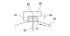
本実施の形態におけるターンテーブル10は、一方への旋回端である第1旋回端(左旋回端)と他方の旋回端である第2旋回端(右旋回端)との間で往復旋回するもので、ターンテーブル10に設けられた単一のブロック12と、ターンテーブル10に臨設されターンテーブル10の両旋回端でブロック12がそれぞれ当接されてその旋回を規制するストッパ14、16とを備えている。図1に示した実施の形態では、ターンテーブル10が90°の範囲で往復旋回するよう両旋回端が設定されている。ターンテーブル10を旋回させる手段は、減速機構を含む電動モータや、直線運動を回転運動に変換するラックおよびピニオンなどからなる機構を含むシリンダなどを採用することができ、特に限定されることはない。図1〜図3に示したブロック12は、ターンテーブル10の外周側面に径方向外側に突出するよう設けられており、両ストッパ14、16は、ターンテーブル10の両旋回端でそれぞれブロック12が当接してターンテーブル10の旋回を規制するよう、ターンブル10の径方向外側に配設されている。なお、ブロック12は、ターンテーブル10の裏面(底面図で示した図1の表面)の外周縁近傍に、ターンテーブル10の径方向外側へ突出するよう設けることもできる。また、ブロック12をターンテーブル10の裏面に下方へ突出させるように設けるとともに、ターンテーブル10に伴って旋回するブロック12と対応する位置であって各旋回端でブロック12と当接するようにストッパ14、16をそれぞれターンテーブル10の下方に配設してもよい。なお、ターンテーブル10の往復旋回角度は、図1に示した実施の形態(90°)に限定されることはなく、任意の位置にストッパ14,16を設けて両旋回端を設定しターンテーブル10を任意の角度で往復旋回させるよう構成することができる。
The
本実施の形態における旋回端検知装置は、ターンテーブル10のブロック12の外側面に開口する単一のエア吹き出し口20と、エア吹き出し口20にエアを供給するエア回路22と、エア回路22のエアの圧力を検出する単一のエア圧力センサ(エア圧検出手段)24と、ターンテーブル10の旋回位置が左旋回端にあるとき、エア吹き出し口20を第1開度に絞るように配設された第1絞り部材26と、ターンテーブル10の旋回位置が右旋回端にあるとき、エア吹き出し口20を第1開度とは異なる第2開度に絞るように配設された第2絞り部材28と、エア圧力センサ24が出力する信号を受け取って、ターンテーブル10の旋回位置が左旋回端と右旋回端のどちらにあるのかを判定する判定手段30とを備えている。
The turning end detection device in the present embodiment includes a
エア回路22は、エアコンプレッサなどのエア供給源32に接続された固定管路22aと、ターンテーブル10に設けられブロック12のエア吹き出し口20に接続される旋回管路22bと、ターンテーブル10を旋回可能に軸支して固定管路22aに対して旋回管路22bをターンテーブル10とともに旋回可能に接続するロータリージョイント22cとを備えている。エア圧力センサ24は、図1に示した実施の形態では固定管路22aの中間部に設けられている。エア圧力センサ24は、検出したエアの圧力を判定手段30に出力する。なお、エア回路22は、図示した実施の形態に限定されることはなく、エアの圧力上昇によって断面積などが大きく変化することがなくエア圧力センサ24がエアの圧力を正確に検出することができるものであれば、フレキシブルパイプによってエア供給源32とターンテーブル10のブロック12のエア吹き出し口20とを接続してもよい。
The
第1絞り部材26と第2絞り部材28は、図1に示した実施の形態では、ターンテーブル10のブロック12がストッパ14または16に当接した状態で、ブロック12の外側面に開口するエア吹き出し口20と所定の間隔(後述する)Sa、Sbの隙間をもって対向するよう配設されたもので、第1絞り部材26と第2絞り部材28は、各ストッパ14、16とそれぞれ一体に成形されている。しかしながら、第1絞り部材26と第2絞り部材28は、各ストッパ14、16とそれぞれ分離して個別に構成することもできる。
In the embodiment shown in FIG. 1, the
図2に示すように、第1絞り部材26のエア吹き出し口20に対する間隔Saは、後述する第2絞り部材28の間隔Sbよりも小さく設定されている。また、図3に示すように、第2絞り部材28のエア吹き出し口20に対する間隔Sbは、上述した第1絞り部材26の間隔Saよりも大きく設定されている。すなわち、図1〜図3に示した実施の形態では、第1絞り部材26と第2絞り部材28のエア吹き出し口20をそれぞれ絞る第1開度と第2開度が、第1絞り部材26と第2絞り部材28のエア吹き出し口20に対して異なる隙間の間隔Sa、Sbによって構成されている。
As shown in FIG. 2, the distance Sa between the
ターンテーブル10が左旋回端に位置してブロック12がストッパ14に当接した状態では、第1絞り部材26のエア吹き出し口20に対する間隔Saが比較的小さいため、エア圧力センサ24が検出するエア回路22内のエアの圧力は、図4の「左旋回端」に示すように比較的高く上昇することとなる。また、ターンテーブル10が左旋回端と右旋回端との間の旋回中の状態では、エア吹き出し口20が第1絞り部材26と第2絞り部材28のいずれにも対向しておらず、エア吹き出し口20からエアが抵抗なく噴出するため、エア圧力センサ24が検出するエア回路22内のエアの圧力は、図4の「旋回途中」に示すように上昇がゼロとなる。ターンテーブル10が右旋回端に位置してブロック12がストッパ16に当接した状態では、第2絞り部材28のエア吹き出し口20に対する間隔Sbが比較的大きいため、エア圧力センサ24が検出するエア回路22内のエアの圧力は、図4の「右旋回端」に示すように上昇するが、「左旋回端」と比較して上昇が小さい。つまり、図4の「左旋回端」と「右旋回端」とでは、エア回路22内の上昇するエアの圧力に差が生じる。
In a state where the
判定手段30は、ターンテーブル10の旋回位置が左旋回端と右旋回端とにある場合のエア回路22内のエアの圧力の上昇に閾値を設定されている。そして、判定手段30は、エア圧力センサ24が検出するエア回路22内のエアの圧力の上昇がゼロ(図4の「旋回途中」)から上昇した場合に、そのエアの圧力の上昇が閾値よりも高いと、ターンテーブル10の旋回位置が図4の「左旋回端」にあると判定し、また、そのエアの圧力の上昇が閾値よりも低いと、ターンテーブル10の旋回位置が図4の「右旋回端」にあると判定する。
The determination means 30 has a threshold value set for an increase in air pressure in the
本発明の旋回端検知装置は、単一のエア吹き出し口20をターンテーブル10に設けることから、このエア吹き出し口20にエアを供給するために必要なエア回路22も単一となる。そして、エア回路22が単一であるため、その内部のエアの圧力を検出するために必要なエア検出センサ24も単一となる。そのため、本発明の旋回端検知装置は、図7に示した従来の技術と比較して簡単な構成となる。
In the turning end detection device of the present invention, since the
また、図7に示した従来の技術にあっては、各ストッパ14’のブロック12’と当接する面にエア吹き出し口20’が開口していたために、ターンテーブル10の旋回位置が旋回端にありブロック12’がストッパ14’または16’に当接しているときに、エア吹き出し口20’から噴出するエアの圧力によってブロック12’がストッパ14’または16’から離れるように押圧されることとなり、ターンテーブル10の旋回位置を旋回端で安定して停止させることが困難となる場合がある。
これに対して、本発明の旋回端検知装置は、本実施の形態では、エア吹き出し口20をターンテーブル10の外側に向かって開口するように設け、第1絞り部材26と第2絞り部材28をエア吹き出し口20と対向するよう配置している。そのため、エアを噴出させるエア吹き出し口20がブロック12の外側面に開口していることから、ターンテーブル10の旋回位置に影響することはなく、ターンテーブル10を旋回端に安定して停止させることができる。
Further, in the prior art shown in FIG. 7, since the
On the other hand, in the present embodiment, the turning end detection device of the present invention is provided with the
さらに、本発明の旋回端検知装置は、第1絞り部材26による第1開度と第2絞り部材28による第2開度とを異ならせたことで、ターンテーブル10の旋回位置がどちらの旋回端にあるかでエア圧力センサ24が検出するエアの圧力の上昇が異なるため、ターンテーブル10の旋回位置がどちらの旋回端にあるかを容易に判定することができる。
Furthermore, the turning end detection device of the present invention makes the turning position of the
次に、本発明の旋回端検知装置の別の実施の形態を図5〜図6に基づいて説明する。なお、この実施の形態においては、上述した実施の形態と同様または相当する部分については同じ符号を付してその説明を省略し、異なる部分についてのみ説明することとする。 Next, another embodiment of the turning end detection device of the present invention will be described with reference to FIGS. In this embodiment, parts that are the same as or correspond to those in the above-described embodiment are denoted by the same reference numerals, description thereof is omitted, and only different parts are described.
図5は、ターンテーブル10の旋回位置が左旋回端にあり、ブロック12がストッパ14に当接している状態を示した部分拡大側面図であり、図6は、ターンテーブル10の旋回位置が右旋回端にあり、ブロック12がストッパ16に当接している状態の異なる実施の形態(a)、(b)を示した部分拡大側面図である。
FIG. 5 is a partially enlarged side view showing a state in which the turning position of the
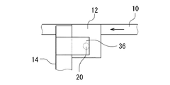
図5に示した第1絞り部材36と図6に示した各第2絞り部材38は、いずれも、各ストッパ14、16にそれぞれ取り付けられており、ブロック12がストッパ14または16に当接した状態で、エア吹き出し口が開口するブロックの外側面に接するか、または、ブロックの外側面に対して同じ間隔で隙間を形成している。
The
図5に示すように、左旋回端における第1絞り部材36は、ブロック12の外側面に開口するエア吹き出し口20をほぼ全面に亘って覆う大きさに成形されている。なお、第1絞り部材36は、ブロック12の外側面に接する場合に、エア吹き出し口20から噴出するエアの圧力によって撓みエアを逃すことができる素材によって構成することができ、また、エア吹き出し口20を完全に覆うことがなく、エアを僅かに逃す部分を有するように成形することもできる。このように、エア吹き出し口20からエアを僅かに逃すよう構成することにより、ターンテーブル10の旋回位置が左旋回端に位置したときに、エア吹き出し口20が第1絞り部材36によって完全に閉塞されることがなく、したがって、エア回路22内のエアの圧力が急激に上昇してエア圧力センサ24が破損するのを防止しすることができる。
As shown in FIG. 5, the
図6の(a)では、右旋回端において、第2絞り部材38aの、ターンテーブル10の旋回方向の長さ(図6の(a)における左方向への長さ)が、ブロック12の外側面に開口するエア吹き出し口20の径S20うちの一部分S38aを開放するよう成形されている。図6の(b)では、右旋回端において、第2絞り部材38bの、ターンテーブル10の旋回方向の幅(図6の(b)における上下方向の長さ)が、ブロック12の外側面に開口するエア吹き出し口20の径S20のうちの一部分S38bを開放するよう成形されている。図6の(a)に示した第2絞り部材38aと(b)に示した第2絞り部材38bは、どちらでも、図5に示した第1絞り部材36と組み合わせることができる。
In FIG. 6A, the length of the
このように構成された第2絞り部材38aまたは38bは、ターンテーブル10の旋回位置が右旋回端にあるとき(つまり、ブロック12がストッパ14に当接しているとき)、図3に示した第2絞り部材28と同様に、エア吹き出し口20からエアの噴出する量が第1絞り部材36よりも多くなり、その結果、エア圧力センサ24が検出するエア回路22内のエアの圧力は、図4の「右旋回端」に示すように上昇はするが、「左旋回端」と比較して上昇が小さく、エア回路22内の上昇するエアの圧力に差が生じる。
The
なお、本発明の旋回端検知装置を備えたターンテーブル10は、一例として上述したようにクーラントを使用する切削加工設備に採用する場合、一般にその加工設備内にはエアコンプレッサなどのエア供給源32を備えていることから、かかるエア供給源32を利用することができる。また、このようにエアを使用する旋回端検知装置は、ブロック12がストッパ14または16に当接したことをスイッチなど電気的に検知するものではないため、特にクーラントを使用する加工整備でも破損する確率が低く、安定してターンテーブルの旋回端を検知することができる。
In addition, when the
さらに、図7に示した従来の技術にあっては、ターンテーブル10の旋回位置が旋回端にありブロック12’がストッパ14’または16’に当接している状態を保持しようとすると、エア吹き出し口20’がブロック12’によって完全に閉塞されることとなり、エア回路22’内のエアの圧力が急激に大きく上昇することから、エア検出センサ24’に大きな負荷がかかって破損するおそれがある。しかしながら、図2と図5に示した第1絞り部材26、36および図3と図6に示した第2絞り部材28、38a、38bは、エア吹き出し口20を完全に閉塞することはなく、エアの噴出を許容するよう構成されているため、エア回路22内の圧力が急激に大きく上昇することはなく、したがってエア検出センサ24にかかる負荷を抑えて破損から保護することができる。
Further, in the conventional technique shown in FIG. 7, if the turn position of the
10:ターンテーブル、 12:ブロック、 14:ストッパ、 16:ストッパ、 20:エア吹き出し口、 22:エア回路、 24:エア圧力センサ、 26:第1絞り部材、 28第2絞り部材、 30:判定手段、 32:エア供給源、 36:第1絞り部材、 38aおよび38b:第2絞り部材、 10: Turntable, 12: Block, 14: Stopper, 16: Stopper, 20: Air outlet, 22: Air circuit, 24: Air pressure sensor, 26: First throttle member, 28 Second throttle member, 30: Determination Means: 32: air supply source; 36: first throttle member; 38a and 38b: second throttle member;
Claims (1)
前記ターンテーブルに設けられた単一のエア吹き出し口と、
前記エア吹き出し口にエアを供給するエア回路と、
前記エア回路のエアの圧力を検出するエア圧検出手段と、
前記ターンテーブルの旋回位置が前記第1旋回端にあるとき、前記エア吹き出し口を第1開度に絞るように配設された第1絞り部材と、
前記ターンテーブルの旋回位置が前記第2旋回端にあるとき、前記エア吹き出し口を前記第1開度とは異なる第2開度に絞るように配設された第2絞り部材と
を備えていることを特徴とするターンテーブルの旋回端検知装置。 The turn position of the turntable that is turned between the first turning end that is the turning end to one side and the second turning end that is the other turning end is at the first turning end or the second turning end. A turntable detecting device for a turntable that detects
A single air outlet provided in the turntable;
An air circuit for supplying air to the air outlet;
Air pressure detecting means for detecting the pressure of air in the air circuit;
A first throttle member disposed so as to throttle the air outlet to a first opening when the turning position of the turntable is at the first turning end;
A second throttle member disposed so as to throttle the air outlet to a second opening different from the first opening when the turning position of the turntable is at the second turning end; A turning table detecting device for a turntable.
Priority Applications (1)
| Application Number | Priority Date | Filing Date | Title |
|---|---|---|---|
| JP2016016038A JP2017132017A (en) | 2016-01-29 | 2016-01-29 | Turntable swivel end detection device |
Applications Claiming Priority (1)
| Application Number | Priority Date | Filing Date | Title |
|---|---|---|---|
| JP2016016038A JP2017132017A (en) | 2016-01-29 | 2016-01-29 | Turntable swivel end detection device |
Publications (1)
| Publication Number | Publication Date |
|---|---|
| JP2017132017A true JP2017132017A (en) | 2017-08-03 |
Family
ID=59504158
Family Applications (1)
| Application Number | Title | Priority Date | Filing Date |
|---|---|---|---|
| JP2016016038A Pending JP2017132017A (en) | 2016-01-29 | 2016-01-29 | Turntable swivel end detection device |
Country Status (1)
| Country | Link |
|---|---|
| JP (1) | JP2017132017A (en) |
Cited By (3)
| Publication number | Priority date | Publication date | Assignee | Title |
|---|---|---|---|---|
| KR102458089B1 (en) * | 2022-08-04 | 2022-10-21 | 추한선 | limit switch device for using universal two ways rotating |
| KR20240000321U (en) * | 2022-08-12 | 2024-02-20 | 추한선 | limit switch device for using universal two ways rotating |
| CN118857105A (en) * | 2024-09-24 | 2024-10-29 | 南通通州意达港口机械有限公司 | A port machinery rotation position detection device |
-
2016
- 2016-01-29 JP JP2016016038A patent/JP2017132017A/en active Pending
Cited By (4)
| Publication number | Priority date | Publication date | Assignee | Title |
|---|---|---|---|---|
| KR102458089B1 (en) * | 2022-08-04 | 2022-10-21 | 추한선 | limit switch device for using universal two ways rotating |
| KR20240000321U (en) * | 2022-08-12 | 2024-02-20 | 추한선 | limit switch device for using universal two ways rotating |
| KR200498482Y1 (en) | 2022-08-12 | 2024-10-30 | 추한선 | limit switch device for using universal two ways rotating |
| CN118857105A (en) * | 2024-09-24 | 2024-10-29 | 南通通州意达港口机械有限公司 | A port machinery rotation position detection device |
Similar Documents
| Publication | Publication Date | Title |
|---|---|---|
| CN103309230B (en) | Detect the sensor device of the safety device state of the device operated in an automatic fashion | |
| JP2017132017A (en) | Turntable swivel end detection device | |
| US9815208B2 (en) | Device for connecting a tool to a robot arm | |
| US9878412B2 (en) | Rotation table | |
| US10130997B2 (en) | Main shaft device and machine tool provided with same | |
| JP6641358B2 (en) | Cylinder device | |
| JP6211851B2 (en) | Clamping device | |
| US10744612B2 (en) | Rotary table device | |
| US8292280B2 (en) | Device for detecting operation of clamp | |
| KR20140002562A (en) | Clamping chuck | |
| US20190039254A1 (en) | Work robot | |
| JP2018522742A (en) | Micro lubricator | |
| US12138761B2 (en) | Apparatus for clamping workpieces on machine tools | |
| JP5368537B2 (en) | Tool floating mechanism | |
| US20240326185A1 (en) | Device for clamping workpieces on machine tools | |
| US10005162B2 (en) | Machine tool including chip conveyor | |
| KR20130047183A (en) | Device for preventing collision between steady rest and tail stock for machine tool | |
| CN105397515A (en) | Self-detecting type two-pin locating clamp | |
| KR100737485B1 (en) | Cooling Water Cutoff Device of Welding Gun | |
| KR100863056B1 (en) | Finger tool device for conveying press panel | |
| EP3364085B1 (en) | Housing cover sealing detection means on a valve control head | |
| JP6840266B2 (en) | Work machine | |
| JP2020131417A (en) | Clamp device | |
| JP4492405B2 (en) | Work detection method | |
| JP6648996B2 (en) | Link type clamp device |