JP2017135486A - Sound image localization processing apparatus and sound image localization processing method - Google Patents
Sound image localization processing apparatus and sound image localization processing method Download PDFInfo
- Publication number
- JP2017135486A JP2017135486A JP2016012043A JP2016012043A JP2017135486A JP 2017135486 A JP2017135486 A JP 2017135486A JP 2016012043 A JP2016012043 A JP 2016012043A JP 2016012043 A JP2016012043 A JP 2016012043A JP 2017135486 A JP2017135486 A JP 2017135486A
- Authority
- JP
- Japan
- Prior art keywords
- transfer characteristic
- measurement
- unit
- transfer
- tap length
- Prior art date
- Legal status (The legal status is an assumption and is not a legal conclusion. Google has not performed a legal analysis and makes no representation as to the accuracy of the status listed.)
- Granted
Links
Images








Classifications
-
- H—ELECTRICITY
- H04—ELECTRIC COMMUNICATION TECHNIQUE
- H04S—STEREOPHONIC SYSTEMS
- H04S7/00—Indicating arrangements; Control arrangements, e.g. balance control
- H04S7/30—Control circuits for electronic adaptation of the sound field
- H04S7/302—Electronic adaptation of stereophonic sound system to listener position or orientation
- H04S7/303—Tracking of listener position or orientation
- H04S7/304—For headphones
-
- H—ELECTRICITY
- H04—ELECTRIC COMMUNICATION TECHNIQUE
- H04R—LOUDSPEAKERS, MICROPHONES, GRAMOPHONE PICK-UPS OR LIKE ACOUSTIC ELECTROMECHANICAL TRANSDUCERS; ELECTRIC HEARING AIDS; PUBLIC ADDRESS SYSTEMS
- H04R1/00—Details of transducers, loudspeakers or microphones
- H04R1/20—Arrangements for obtaining desired frequency or directional characteristics
- H04R1/32—Arrangements for obtaining desired frequency or directional characteristics for obtaining desired directional characteristic only
- H04R1/40—Arrangements for obtaining desired frequency or directional characteristics for obtaining desired directional characteristic only by combining a number of identical transducers
- H04R1/406—Arrangements for obtaining desired frequency or directional characteristics for obtaining desired directional characteristic only by combining a number of identical transducers microphones
-
- H—ELECTRICITY
- H04—ELECTRIC COMMUNICATION TECHNIQUE
- H04R—LOUDSPEAKERS, MICROPHONES, GRAMOPHONE PICK-UPS OR LIKE ACOUSTIC ELECTROMECHANICAL TRANSDUCERS; ELECTRIC HEARING AIDS; PUBLIC ADDRESS SYSTEMS
- H04R3/00—Circuits for transducers
- H04R3/005—Circuits for transducers for combining the signals of two or more microphones
-
- H—ELECTRICITY
- H04—ELECTRIC COMMUNICATION TECHNIQUE
- H04R—LOUDSPEAKERS, MICROPHONES, GRAMOPHONE PICK-UPS OR LIKE ACOUSTIC ELECTROMECHANICAL TRANSDUCERS; ELECTRIC HEARING AIDS; PUBLIC ADDRESS SYSTEMS
- H04R5/00—Stereophonic arrangements
- H04R5/033—Headphones for stereophonic communication
-
- H—ELECTRICITY
- H04—ELECTRIC COMMUNICATION TECHNIQUE
- H04R—LOUDSPEAKERS, MICROPHONES, GRAMOPHONE PICK-UPS OR LIKE ACOUSTIC ELECTROMECHANICAL TRANSDUCERS; ELECTRIC HEARING AIDS; PUBLIC ADDRESS SYSTEMS
- H04R5/00—Stereophonic arrangements
- H04R5/04—Circuit arrangements, e.g. for selective connection of amplifier inputs/outputs to loudspeakers, for loudspeaker detection, or for adaptation of settings to personal preferences or hearing impairments
-
- H—ELECTRICITY
- H04—ELECTRIC COMMUNICATION TECHNIQUE
- H04S—STEREOPHONIC SYSTEMS
- H04S3/00—Systems employing more than two channels, e.g. quadraphonic
- H04S3/008—Systems employing more than two channels, e.g. quadraphonic in which the audio signals are in digital form, i.e. employing more than two discrete digital channels
-
- H—ELECTRICITY
- H04—ELECTRIC COMMUNICATION TECHNIQUE
- H04S—STEREOPHONIC SYSTEMS
- H04S7/00—Indicating arrangements; Control arrangements, e.g. balance control
- H04S7/30—Control circuits for electronic adaptation of the sound field
- H04S7/302—Electronic adaptation of stereophonic sound system to listener position or orientation
-
- H—ELECTRICITY
- H04—ELECTRIC COMMUNICATION TECHNIQUE
- H04S—STEREOPHONIC SYSTEMS
- H04S2400/00—Details of stereophonic systems covered by H04S but not provided for in its groups
- H04S2400/01—Multi-channel, i.e. more than two input channels, sound reproduction with two speakers wherein the multi-channel information is substantially preserved
-
- H—ELECTRICITY
- H04—ELECTRIC COMMUNICATION TECHNIQUE
- H04S—STEREOPHONIC SYSTEMS
- H04S2400/00—Details of stereophonic systems covered by H04S but not provided for in its groups
- H04S2400/15—Aspects of sound capture and related signal processing for recording or reproduction
-
- H—ELECTRICITY
- H04—ELECTRIC COMMUNICATION TECHNIQUE
- H04S—STEREOPHONIC SYSTEMS
- H04S2420/00—Techniques used stereophonic systems covered by H04S but not provided for in its groups
- H04S2420/01—Enhancing the perception of the sound image or of the spatial distribution using head related transfer functions [HRTF's] or equivalents thereof, e.g. interaural time difference [ITD] or interaural level difference [ILD]
Landscapes
- Engineering & Computer Science (AREA)
- Physics & Mathematics (AREA)
- Acoustics & Sound (AREA)
- Signal Processing (AREA)
- Health & Medical Sciences (AREA)
- Otolaryngology (AREA)
- Multimedia (AREA)
- General Health & Medical Sciences (AREA)
- Stereophonic System (AREA)
Abstract
【課題】環境に応じた適切な伝達特性を用いて処理することができる音像定位処理装置、及び音像定位処理方法を提供する。【解決手段】伝達特性測定部35は、畳み込み演算部で再生信号に対して畳み込み演算を行うため、左右のスピーカから左右のマイクまでの第1の伝達特性をそれぞれ測定する。環境測定部39は、左右のスピーカから出力された環境測定用信号を左右のマイクで収音し、伝達特性測定用信号の振幅レベルと、伝達特性のタップ長とを設定し、左右のスピーカから音を出力していない状態において左右のマイクで収音し、第2の伝達特性を測定する。補正処理部38は、第2の伝達特性に基づいて、第1の伝達特性の低域を補正する【選択図】図4A sound image localization processing apparatus and a sound image localization processing method capable of processing using an appropriate transfer characteristic according to the environment are provided. A transfer characteristic measuring unit measures first transfer characteristics from left and right speakers to left and right microphones in order to perform a convolution operation on a reproduction signal by a convolution operation unit. The environment measurement unit 39 picks up the environment measurement signal output from the left and right speakers with the left and right microphones, sets the amplitude level of the transfer characteristic measurement signal and the tap length of the transfer characteristic, and outputs from the left and right speakers. In a state where no sound is output, sound is collected by the left and right microphones, and the second transfer characteristic is measured. The correction processing unit 38 corrects the low frequency range of the first transfer characteristic based on the second transfer characteristic.
Description
本発明は、音像定位処理装置、及び音像定位処理方法に関する。 The present invention relates to a sound image localization processing apparatus and a sound image localization processing method.
音像定位技術として、ヘッドホンを用いて受聴者の頭部の外側に音像を定位させる頭外定位技術がある。頭外定位技術では、ヘッドホンから耳までの特性をキャンセルし、ステレオスピーカから耳までの4本の特性を与えることにより、音像を頭外に定位させている。特許文献1には、頭外に音像を定位させる方法として、受聴者の頭部伝達関数HRTF(Head Related Transfer Function)、及び外耳道伝達関数を用いる方法が開示されている。また、HRTFは個人差が大きく、特に耳介形状の違いによるHRTFの変化が著しいことが知られている。 As a sound image localization technique, there is an out-of-head localization technique that uses a headphone to localize a sound image outside the listener's head. In the out-of-head localization technology, the sound image is localized out of the head by canceling the characteristics from the headphones to the ears and giving four characteristics from the stereo speakers to the ears. Patent Document 1 discloses a method using a listener's head related transfer function HRTF (Head Related Transfer Function) and an external auditory canal transfer function as a method of localizing a sound image outside the head. Further, it is known that the HRTF has a large individual difference, and the change in the HRTF due to the difference in the pinna shape is particularly remarkable.
頭外定位再生においては、2チャンネル(以下、chと記載)のスピーカから発した伝達特性測定用信号(インパルス音等)を聴取者本人の耳に設置したマイクで録音する。そして、インパルス応答から頭部伝達関数を算出して、フィルタを作成する。作成したフィルタを2chの音楽信号に畳み込むことにより、頭外定位再生を実現することができる。 In out-of-head localization playback, a transfer characteristic measurement signal (impulse sound, etc.) emitted from a speaker of two channels (hereinafter referred to as “ch”) is recorded by a microphone installed in the ear of the listener. Then, a head-related transfer function is calculated from the impulse response to create a filter. By convolving the created filter with a 2ch music signal, out-of-head localization reproduction can be realized.
受聴者の耳(外耳道入口が望ましい)にマイクを設置することで、正確に特性を測定することができる。しかしながら、受聴者の外耳道入口にマイクを設置した上での測定は煩雑である。そこで、特許文献2には、マイクを内蔵したヘッドホンによって、伝達特性を測定する方法が開示されている。
By installing a microphone in the listener's ear (preferably the ear canal entrance), the characteristics can be measured accurately. However, measurement with a microphone installed at the listener's ear canal entrance is complicated. Thus,
このような伝達関数(伝達特性ともいう)を測定するために、スピーカなどの音源が設置された専用の測定室で測定を行うことが一般である。例えば測定室は、部屋の音響特性が計算されたオーディオルームや、壁に吸音材を貼り、部屋の反射をなくした無響室等がある。測定室内において、スピーカから伝達特性測定用信号(インパルス音等)を発生させる。そして、受聴者やダミーヘッドの外耳道入口または鼓膜入口に設置されたマイクを用いて、インパルス応答を測定する。通常、このような測定室は、不要な音の反射や残響が少なく、かつ音響特性が考慮されたスピーカ配置を施した室内環境である。 In order to measure such a transfer function (also referred to as transfer characteristics), the measurement is generally performed in a dedicated measurement room in which a sound source such as a speaker is installed. For example, the measurement room includes an audio room in which the acoustic characteristics of the room are calculated, an anechoic room in which a sound absorbing material is attached to a wall, and reflection of the room is eliminated. In the measurement chamber, a signal for measuring transfer characteristics (such as an impulse sound) is generated from a speaker. Then, the impulse response is measured using a microphone installed at the ear canal entrance or the eardrum entrance of the listener or the dummy head. In general, such a measurement room is an indoor environment in which unnecessary sound is reflected and reverberant and a speaker arrangement is provided in consideration of acoustic characteristics.
特許文献2のヘッドホンとマイクを用いることで、測定室以外の環境でもインパルス応答を測定できる。例えば、実際の受聴者が受聴する環境、具体的には自宅の部屋等の様々な環境でインパルス応答を測定できる。しかしながら、音響特性が考慮されていない部屋の形状やスピーカの配置では、想定外の反射音が発生することがある。さらに、暗騒音や突発騒音などの環境音がノイズとして測定されてしまうことがある。したがって、音像定位処理に必要な伝達特性の測定精度が低下してしまうおそれがある。
By using the headphones and microphone of
本発明は上記の点に鑑みなされたもので、環境に応じた適切な伝達特性を用いて処理することができる音像定位処理装置、及び音像定位処理方法を提供することを目的とする。 The present invention has been made in view of the above points, and an object of the present invention is to provide a sound image localization processing apparatus and a sound image localization processing method capable of processing using an appropriate transfer characteristic according to the environment.
本発明の一態様にかかる音像定位処理装置は、左右のスピーカと、左右のマイクと、前記左右のスピーカから出力された伝達特性測定用信号を前記左右のマイクで収音することで、前記左右のスピーカから前記左右のマイクまでの第1の伝達特性をそれぞれ測定する伝達特性測定部と、前記第1の伝達特性を用いて再生信号に対して畳み込み演算を行う畳み込み演算部と、前記左右のスピーカから出力された環境測定用信号を前記左右のマイクで収音する第1の環境測定と、前記左右のスピーカから音を出力していない状態において前記左右のマイクで収音する第2の環境測定とを行い、前記第1の環境測定の結果に基づいて、前記伝達特性測定用信号の振幅レベルと、前記第1の伝達特性のタップ長とを設定し、前記第2の環境測定の結果に基づいて、第2の伝達特性を測定する環境測定部と、前記第2の伝達特性に基づいて、前記第1の伝達特性の低域を補正する補正処理部と、を備えるものである。 The sound image localization processing apparatus according to an aspect of the present invention collects the left and right speakers, the left and right microphones, and the left and right microphones by collecting the transfer characteristic measurement signals output from the left and right speakers. A transfer characteristic measuring unit that measures the first transfer characteristic from each of the speakers to the left and right microphones, a convolution operation part that performs a convolution operation on the reproduction signal using the first transfer characteristic, and the left and right First environment measurement for collecting environmental measurement signals output from the speakers with the left and right microphones, and a second environment for collecting sound with the left and right microphones in a state where no sound is output from the left and right speakers. Measurement, and setting the amplitude level of the transfer characteristic measurement signal and the tap length of the first transfer characteristic based on the result of the first environment measurement, and the result of the second environment measurement Based on the environment measurement unit for measuring the second transmission characteristic, on the basis of the second transfer characteristic, in which and a correction processing unit for correcting the low frequency of the first transmission characteristic.
本発明の一態様にかかる音像定位処理方法は、左右のスピーカと左右のマイクとの間の第1の伝達特性を用いて音像定位処理を行う音像定位処理方法であって、前記左右のスピーカから出力された環境測定用信号を前記左右のマイクで収音する第1の環境測定と、前記左右のスピーカから音を出力していない状態において前記左右のマイクで収音する第2の環境測定とを行い、前記第1の環境測定の結果に基づいて、伝達特性測定用信号の振幅レベルと、前記左右のスピーカから前記左右のマイクまでの前記第1の伝達特性のタップ長とを設定し、前記第2の環境測定の結果に基づいて、第2の伝達特性を測定する環境測定ステップと、前記第1の環境測定の結果に基づいて設定された前記伝達特性測定用信号を前記左右のスピーカから出力し、前記伝達特性測定用信号を前記左右のマイクで収音することで、前記第1の伝達特性をそれぞれ測定する伝達特性測定ステップと、前記第2の伝達特性に基づいて、前記第1の伝達特性の低域を補正する補正ステップと、を含むものである。 A sound image localization processing method according to an aspect of the present invention is a sound image localization processing method that performs sound image localization processing using a first transfer characteristic between left and right speakers and left and right microphones, and includes the left and right speakers. A first environmental measurement for collecting the output environmental measurement signal by the left and right microphones; and a second environmental measurement for collecting the sound by the left and right microphones when no sound is output from the left and right speakers. And setting the amplitude level of the transfer characteristic measurement signal and the tap length of the first transfer characteristic from the left and right speakers to the left and right microphones based on the result of the first environment measurement, An environment measuring step for measuring a second transfer characteristic based on the result of the second environment measurement, and the transfer characteristic measurement signal set based on the result of the first environment measurement are used as the left and right speakers. Output from The transmission characteristics measurement signal is collected by the left and right microphones to measure the first transmission characteristics, respectively, and the first transmission is based on the second transmission characteristics. And a correction step for correcting the low frequency range of the characteristic.
本発明によれば、環境に応じた適切な伝達特性を用いて処理することができる音像定位処理装置、及び音像定位処理方法を提供することができる。 According to the present invention, it is possible to provide a sound image localization processing apparatus and a sound image localization processing method that can perform processing using appropriate transfer characteristics according to the environment.
本実施の形態にかかる音像定位処理装置の一例である頭外定位処理の概要について説明する。
本実施形態にかかる頭外定位処理は、個人の空間音響伝達特性(空間音響伝達関数ともいう)と外耳道伝達特性(外耳道伝達関数ともいう)を用いて頭外定位処理を行うものである。本実施形態では、スピーカから聴取者の耳までの空間音響伝達特性、及びヘッドホンを装着した状態での外耳道伝達特性(外耳道伝達関数ともいう)を用いて頭外定位処理を実現している。
An outline of out-of-head localization processing, which is an example of a sound image localization processing device according to the present embodiment, will be described.
The out-of-head localization processing according to the present embodiment performs out-of-head localization processing using an individual's spatial acoustic transfer characteristic (also referred to as a spatial acoustic transfer function) and an external auditory canal transfer characteristic (also referred to as an external auditory canal transfer function). In the present embodiment, the out-of-head localization processing is realized by using the spatial acoustic transfer characteristic from the speaker to the listener's ear and the external auditory canal transfer characteristic (also referred to as the external auditory canal transfer function) in a state where headphones are worn.
本実施の形態では、ヘッドホン装着状態でのヘッドホンスピーカユニットから外耳道入口までの特性である外耳道伝達特性が利用されている。そして、外耳道伝達特性の逆特性(外耳道補正関数ともいう)を用いてフィルタ処理を行うことで、外耳道伝達特性をキャンセルすることができる。 In the present embodiment, the ear canal transmission characteristic, which is the characteristic from the headphone speaker unit to the ear canal entrance with the headphone mounted, is used. Then, the ear canal transfer characteristic can be canceled by performing the filtering process using the inverse characteristic of the ear canal transfer characteristic (also referred to as the ear canal correction function).
本実施の形態にかかる頭外定位処理装置は、パーソナルコンピュータ、スマートホン、タブレットPCなどの情報処理装置であり、プロセッサ等の処理手段、メモリやハードディスクなどの記憶手段、液晶モニタ等の表示手段、タッチパネル、ボタン、キーボード、マウスなどの入力手段、ヘッドホン又はイヤホンを有する出力手段を備えている。 The out-of-head localization processing apparatus according to the present embodiment is an information processing apparatus such as a personal computer, a smartphone, or a tablet PC, processing means such as a processor, storage means such as a memory or a hard disk, display means such as a liquid crystal monitor, Input means such as a touch panel, buttons, a keyboard, and a mouse, and output means having headphones or earphones are provided.
実施の形態1.
本実施の形態にかかる音場再生装置の一例である頭外定位処理装置100を図1に示す。図1は、頭外定位処理装置のブロック図である。頭外定位処理装置100は、ヘッドホン43を装着するユーザUに対して音場を再生する。そのため、頭外定位処理装置100は、LchとRchのステレオ入力信号XL、XRについて、音像定位処理を行う。LchとRchのステレオ入力信号XL、XRは、CD(Compact Disc)プレーヤなどから出力される音楽再生信号である。なお、頭外定位処理装置100は、物理的に単一な装置に限られるものではなく、一部の処理が異なる装置で行われてもよい。例えば、一部の処理がパソコンなどにより行われ、残りの処理がヘッドホン43に内蔵されたDSP(Digital Signal Processor)などにより行われてもよい。
Embodiment 1 FIG.
FIG. 1 shows an out-of-head
頭外定位処理装置100は、頭外定位処理部10と、フィルタ部41、フィルタ部42、及びヘッドホン43を備えている。
The out-of-head
頭外定位処理部10は、畳み込み演算部11〜12、21〜22、及び加算器24、25を備えている。畳み込み演算部11〜12、21〜22は、空間音響伝達特性を用いた畳み込み処理を行う。頭外定位処理部10には、CDプレーヤなどからのステレオ入力信号XL、XRが入力される。頭外定位処理部10には、空間音響伝達特性が設定されている。頭外定位処理部10は、各chのステレオ入力信号XL、XRに対し、空間音響伝達特性を畳み込む。空間音響伝達特性はユーザU本人の頭部や耳介で測定した頭部伝達関数HRTFでもよいし、ダミーヘッドまたは第三者の頭部伝達関数であってもよい。これらの伝達特性は、その場で測定してもよいし、予め用意してもよい。
The out-of-head
空間音響伝達特性は、4つの伝達特性Hls、Hlo、Hro、Hrsを有している。4つの伝達特性は、後述する測定装置を用いて求めることができる。 The spatial acoustic transfer characteristic has four transfer characteristics Hls, Hlo, Hro, and Hrs. The four transfer characteristics can be obtained by using a measuring device described later.
そして、畳み込み演算部11は、Lchのステレオ入力信号XLに対して伝達特性Hlsを畳み込む。畳み込み演算部11は、畳み込み演算データを加算器24に出力する。畳み込み演算部21は、Rchのステレオ入力信号XRに対して伝達特性Hroを畳み込む。畳み込み演算部21は、畳み込み演算データを加算器24に出力する。加算器24は2つの畳み込み演算データを加算して、フィルタ部41に出力する。
The
畳み込み演算部12は、Lchのステレオ入力信号XLに対して伝達特性Hloを畳み込む。畳み込み演算部12は、畳み込み演算データを、加算器25に出力する。畳み込み演算部22は、Rchのステレオ入力信号XRに対して伝達特性Hrsを畳み込む。畳み込み演算部22は、畳み込み演算データを、加算器25に出力する。加算器25は2つの畳み込み演算データを加算して、フィルタ部42に出力する。
The
フィルタ部41、42には外耳道伝達特性をキャンセルする逆フィルタが設定されている。そして、頭外定位処理部10での処理が施された再生信号に逆フィルタを畳み込む。フィルタ部41で加算器24からのLch信号に対して、逆フィルタを畳み込む。同様に、フィルタ部42は加算器25からのRch信号に対して逆フィルタを畳み込む。逆フィルタは、ヘッドホン43を装着した場合に、ヘッドホンユニットからマイクまでの特性をキャンセルする。すなわち、外耳道入口にマイクを配置したとき、ユーザ各人の外耳道入口とヘッドホンの再生ユニット間、あるいは鼓膜とヘッドホンの再生ユニット間の伝達特性をキャンセルする。逆フィルタは、ユーザU本人の耳介で外耳道伝達関数をその場で測定した結果から算出してもよいし、ダミーヘッド等の任意の外耳道伝達関数から算出したヘッドホン特性の逆フィルタを予め用意してもよい。
In the
フィルタ部41は、補正されたLch信号をヘッドホン43の左ユニット43Lに出力する。フィルタ部42は、補正されたRch信号をヘッドホン43の右ユニット43Rに出力する。ユーザUは、ヘッドホン43を装着している。ヘッドホン43は、Lch信号とRch信号をユーザUに向けて出力する。これにより、ユーザUの頭外に定位された音像を再生することができる。
The
(測定装置)
図2及び図3を用いて、空間音響伝達特性(以下、伝達特性とする)を測定する測定装置について説明する。図2は、測定装置の構成を模式的に示す図である。図3は、測定装置200の制御構成を示すブロック図である。なお、測定装置200は、図1に示す頭外定位処理装置100と共通の装置であってもよい。あるいは、測定装置200の一部又は全部が頭外定位処理装置100と異なる装置となっていてもよい。
(measuring device)
A measurement apparatus that measures spatial acoustic transfer characteristics (hereinafter referred to as transfer characteristics) will be described with reference to FIGS. 2 and 3. FIG. 2 is a diagram schematically illustrating the configuration of the measurement apparatus. FIG. 3 is a block diagram illustrating a control configuration of the
図2に示すように、測定装置200は、ステレオスピーカ5とステレオマイク2を有している。ステレオスピーカ5が測定環境に設置されている。測定環境は、音響特性が考慮されていない環境(例えば部屋の形状が左右非対称等)や、ノイズとなる環境音が発生している環境となっている。より具体的には、測定環境は、ユーザUの自宅の部屋やオーディオシステムの販売店舗やショールーム等でもよい。このような測定環境では、エアコンなどによって暗騒音が発生していることがある。また、自動車の往来などによって突発騒音が発生することがある。また、測定環境が音響特性を考慮していないレイアウトとなっていることがある。自宅の部屋では、家具などが左右非対称に配置されていることもある。スピーカが部屋に対して左右対称に配置されていないこともある。さらに、窓、壁面、床面、天井面からの反射による不要な残響が発生することもある。本実施の形態では、理想的ではない測定環境であっても、適切な伝達特性を測定するための処理を行っている。
As shown in FIG. 2, the measuring
ステレオスピーカ5は、左スピーカ5Lと右スピーカ5Rを備えている。例えば、受聴者1の前方に左スピーカ5Lと右スピーカ5Rが設置されている。左スピーカ5Lと右スピーカ5Rは、インパルス応答測定を行うためのインパルス音等を出力する。
The stereo speaker 5 includes a
ステレオマイク2は、左のマイク2Lと右のマイク2Rを有している。左のマイク2Lは、受聴者1の左耳9Lに設置され、右のマイク2Rは、受聴者1の右耳9Rに設置されている。具体的には、左耳9L、右耳9Rの外耳道入口又は鼓膜位置にマイク2L、2Rを設置することが好ましい。マイク2L、2Rは、ステレオスピーカ5から出力された信号を収音する。受聴者1は、人でもよく、ダミーヘッドでもよい。すなわち、本実施形態において、受聴者1は人だけでなく、ダミーヘッドを含む概念である。
The
左右のスピーカ5L、5Rで出力されたインパルス音をマイク2L、2Rで測定することでインパルス応答が測定される。これにより、左スピーカ5Lと左マイク2Lとの間の伝達特性Hls、左スピーカ5Lと右マイク2Rとの間の伝達特性Hlo、右スピーカ5Lと左マイク2Lとの間の伝達特性Hro、右スピーカ5Rと右マイク2Rとの間の伝達特性Hrsが測定される。
The impulse response is measured by measuring the impulse sound output from the left and
測定装置200は、インパルス応答測定に基づいて、伝達特性Hls〜Hrsを測定する。図1で示したように、頭外定位処理装置100が、左右のスピーカ5L、5Rと左右のマイク2L、2Rとの間の伝達特性を用いて頭外定位処理を行う。すなわち、伝達特性を音楽再生信号に畳み込むことにより、頭外定位処理を行う。
The measuring
測定装置200の制御構成について、図3を用いて説明する。測定装置200は、マイク2L、2Rと、増幅器3L、3Rと、A/D変換器4L、4Rと、スピーカ5L、5Rと、増幅器6L、6Rと、D/A変換器7L、7Rと、測定部30と、表示部60と、入力部70と、記憶部80と、操作部90と、を備えている。
A control configuration of the measuring
表示部60は、液晶モニタなどの表示デバイスを備えている。表示部60は、伝達特性等を測定するための設定画面等を表示する。また、表示部60は、適宜測定結果や測定時のエラー等を表示する。
The
入力部70は、タッチパネル、ボタン、キーボード、マウスなどの入力デバイスを有しており、受聴者1からの入力を受け付ける。具体的には、入力部70は、伝達特性を測定するため、設定画面上での入力を受け付ける。
The
操作部90は、表示部60、及び入力部70を制御する制御部となる。すなわち、操作部90は、表示部60に表示信号を出力する。また、入力部70によって受け付けられた入力に応じた入力信号を測定部30に出力する。
The
記憶部80はメモリやハードディスクなどの記憶装置を有しており、伝達特性や各種の初期値を記憶する。さらに、記憶部80は、測定を行うための設定などを記憶する。例えば、記憶部80は、後述する規定回数、規定値、閾値などを記憶している。また、後述するように記憶部80は、低域補正用の伝達特性を記憶している。
The
測定部30は、各種測定を行うための制御を行う。測定部30は、スピーカ5L、5Rに出力される信号を生成する。また、測定部30は、マイク2L、2Rからの収音信号に対して処理を行う。
The
具体的には、測定部30は、テスト測定と伝達特性測定を行う。テスト測定では、スピーカ5L、5Rが、環境測定用信号を出力する。そして、スピーカ5L、5Rから出力された環境測定用信号をマイク2L、2Rが収音する(第1の環境測定)。測定部30は、テスト測定での測定結果に基づいて、伝達特性測定用信号を生成する。より具体的には、環境測定での測定結果に基づいて、伝達特性測定用信号の出力振幅レベル、タップ長、低域スレッショルドのパラメータを設定する。
Specifically, the
伝達特性測定では、スピーカ5L、5Rが、伝達特性測定用信号を出力する。そして、スピーカ5L、5Rから出力された伝達特性測定用信号をマイク2L、2Rが収音する。測定部30、収音信号に基づいて、伝達特性を測定する。なお、測定部30による測定については後述する。
In the transfer characteristic measurement, the
測定部30は、環境測定用信号、又は伝達特性測定用信号(以下、まとめて測定用信号とする)をD/A変換器7L、7Rに出力する。D/A変換器7L、7Rは、測定用信号をD/A変換して、増幅器6L、6Rに出力する。増幅器6L、6Rは測定用信号を増幅して、スピーカ5L、5Rに出力する。そして、スピーカ5L、5Rが測定用信号を出力する。
The
また、マイク2L、2Rは、スピーカ5L、5Rで出力された測定用信号を収音する。マイク2L、2Rは、収音した測定用信号に応じた収音信号を増幅器3L、3Rに出力する。増幅器3L、3Rは、収音信号を増幅して、A/D変換器4L、4Rに出力する。A/D変換器4L、4Rは、収音信号をA/D変換して、測定部30に出力する。測定部30は、A/D変換された収音信号に対してデジタル処理を行う。
The
測定室以外の暗騒音が多い環境や部屋の反射など音響特性が考慮されていない部屋で測定を行った場合、低域に不要な暗騒音が入ったり、部屋による不要な反射音や残響による影響が伝達関数に混入したりする。この場合、測定の精度が劣化してしまう。したがって、伝達関数を測定する前に環境測定を行うことで、不要な暗騒音や反射音、残響による影響を軽減する補正処理を行う。この補正処理により、どのような部屋で測定しても精度の高い伝達関数を得ることができる。 When measurement is performed in an environment other than the measurement room where there is a lot of background noise or where the acoustic characteristics such as room reflection are not taken into account, unnecessary background noise may be generated in the low range, or the effect of unnecessary reflection or reverberation from the room. Mixed into the transfer function. In this case, measurement accuracy deteriorates. Therefore, by performing environmental measurement before measuring the transfer function, correction processing is performed to reduce the influence of unnecessary background noise, reflected sound, and reverberation. With this correction processing, a transfer function with high accuracy can be obtained regardless of the measurement in any room.
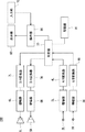
次に、測定部30における測定処理の詳細について、図4、及び図5を用いて説明する。図4は、測定部30の構成を示す制御ブロック図である。図5は、測定部30における測定処理を示すフローチャートである。
Next, details of the measurement process in the
測定部30は、環境測定部39と、伝達特性測定部35と、補正処理部38とを備えている。環境測定部39は、環境測定用信号を生成し出力するテスト測定部31と、取得した伝達特性から各パラメータを決定する出力振幅レベル判定部32と、タップ長検出部33と、低域スレッショルド検出部34と、を備えている。補正処理部38は、低域補正部37を備えている。
The
まず、環境測定部39が環境測定を行う(S100)。環境測定は、暗騒音や不要な反射等の影響を受けないように、できるだけ短い最適な測定タップ長による伝達特性測定用信号を生成するために行われる。ここでは、左右のスピーカ5L、5Rから出力された環境測定用信号を左右のマイク2L、2Rで収音することで、環境測定を行う。
First, the
そして、伝達特性測定部35が、伝達特性測定を行う(S200)。ステップS100での測定結果に基づいて設定された伝達特性測定用信号を左右のスピーカ5L、5Rから出力する。そして、伝達特性測定用信号を左右のマイク2L、2Rで収音することで、左右のスピーカ5L、5Rから左右のマイク2L、2Rまでの伝達特性(第1の伝達特性)をそれぞれ測定する。
Then, the transfer
補正処理部38が、伝達特性に対して補正処理を行う(S300)。すなわち、ステップS200で測定された伝達特性を補正する。
The
(環境測定)
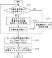
ステップS100の環境測定について、図6を用いて説明する。図6は、環境測定の処理を示すフローチャートである。出力振幅レベル判定部32が出力振幅レベル判定処理を行う(S110)。出力振幅レベル判定処理により、スピーカ5L、5Rから出力される伝達特性測定用信号の出力振幅レベルを設定することができる。出力振幅レベル判定部32は、測定環境に最適な出力振幅レベルを判定する。例えば、出力振幅レベル判定部32が判定した出力振幅レベルに基づいて、伝達特性測定時の増幅器6L、6Rの出力ゲインが設定される。これにより、測定環境に適した出力振幅レベルの伝達特性測定用信号を生成することができる。
(Environmental measurement)
The environment measurement in step S100 will be described with reference to FIG. FIG. 6 is a flowchart showing the environment measurement process. The output amplitude
次に、タップ長検出部33がタップ長検出処理を行う(S130)。タップ長検出処理により、左マイク2L、右マイク2Rで収音される収音信号のタップ長、すなわち、測定サンプリング数が設定される。タップ長を長くするほど、低域の伝達測定を精度よく測定することができるようになるが、測定時間、及び処理時間が長くなるため、処理負荷がかかる。したがって、タップ長検出部33は、測定環境に最適なタップ長を検出する。
Next, the tap
そして、低域スレッショルド検出部34が低域スレッショルド検出処理を行う(S170)。低域スレッショルド検出部34では、周波数の閾値を検出し、後述の低域補正処理において、閾値以下の周波数帯域について、予め用意した任意の伝達特性の周波数特性と置き換えることで低域を補正する。低域スレッショルドは、測定された伝達特性に対して補正が必要な補正帯域と補正が不要な非補正帯域とを分ける周波数の閾値である。
Then, the low
(出力振幅レベル判定)
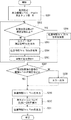
次に、ステップS110の出力振幅レベル判定処理について、図7を用いて説明する。図7は、出力振幅レベル判定処理を示すフローチャートである。図7では、環境測定用信号PreT_sigを左スピーカ5Lから出力した場合の処理を中心に説明し、右スピーカ5Rに関する処理については適宜説明を省略する。図7での処理は、主に、テスト測定部31、及び出力振幅レベル判定部32によって実施される。テスト測定部31は、実際のテスト測定に応じて、複数種類の環境測定用信号を生成して、スピーカ5L、5Rに出力する。
(Output amplitude level judgment)
Next, the output amplitude level determination process in step S110 will be described with reference to FIG. FIG. 7 is a flowchart showing the output amplitude level determination process. In FIG. 7, the processing when the environment measurement signal PreT_sig is output from the left speaker 5 </ b> L will be mainly described, and the processing regarding the right speaker 5 </ b> R will be appropriately omitted. The processing in FIG. 7 is mainly performed by the
まず、テスト測定部31は、受聴者1の測定開始要求(図4のI)を操作部90から受け付けると、テストの実施回数n=0とする(S111)。nはテストの実施回数を示す整数である。そして、テスト測定部31が環境測定用信号PreT_Sigを規定回数出力したか否かを判定する(S112)。すなわち、nが規定回数(例えば、10回)に到達したか否かを判定する。ここでは、n=0であるため、テスト測定部31が規定回数出力していないと判定する(S112のNO)。すると、テスト測定部31が、環境測定用信号PreT_Sigを左スピーカ5Lから出力させる。環境測定用信号PreT_Sigは、例えば、十分に小さい振幅のインパルス音である。具体的には、環境測定用信号PreT_Sigの振幅を最大の環境測定用信号の振幅レベルの10%程度とすることができる。
First, when the
そして、テスト測定部31は、左右のマイク2L、2Rで収音した収音信号に基づいて、左スピーカ5Lから左右のマイク2L、2Rまでの伝達特性PreT_Phls、PreT_Phloを取得する(S114)。なお、伝達特性PreT_Phls、PreT_Phloは、それぞれ、環境測定用信号PreT_sigを出力した時の図2に示す空間伝達特性Hls、Hloに対応している。すなわち、伝達特性PreT_Phlsは左スピーカ5Lと左マイク2L間の伝達特性であり、伝達特性PreT_Phloは左スピーカ5Lと右マイク2R間の伝達特性である。テスト測定部31は、伝達特性PreT_Phlo、PreT_Phloを出力振幅レベル判定部32に出力する(図4のA)。
Then, the
出力振幅レベル判定部32は、右マイク2Rで測定した伝達特性PreT_Phloの振幅レベルが規定値以上であるか否かを判定する(S115)。テスト測定部31は、伝達特性PreT_Phloの振幅レベルが規定値以上となっていない場合(S115のNO)、環境測定用信号PreT_sigの出力振幅レベルを+10%する(S116)。すなわち、テスト測定部31は、伝達特性PreT_Phloの振幅レベルが規定値に到達していない場合、環境測定用信号PreT_sigの振幅を10%上昇させる。そして、テスト測定部31は、nをインクリメントして(nに1を加え)(S117)、ステップS112に戻る。
The output amplitude
そして、テスト測定部31は、ステップS112またはステップS115にてYESと判定されるまで、ステップS112〜S117の処理を繰り返す。すなわち、テスト測定部31は、環境測定用信号PreT_sigを10回出力するまで、または、伝達特性PreT_Phloの振幅レベルが規定値以上となるまで、ステップS112〜S117の処理を実行する。このようにすることで、環境測定用信号PreT_sigの振幅を徐々に上げながら、テスト測定を行うことができる。テスト測定部31は、マイク2Rが適切な振幅レベルの収音信号を出力するまで、環境測定用信号PreT_sigの振幅を増加させる。
And the
そして、環境測定用信号PreT_sigを規定回数出力した場合(S112のYES)、又は、伝達特性PreT_Phloの振幅レベルが規定値以上となった場合(S115のYES)、出力振幅レベル判定部32が出力振幅レベルPgainLを決定する(S118)。すなわち、出力振幅レベル判定部32が、伝達特性PreT_Phloの振幅レベルに基づいて、伝達特性測定時の出力振幅レベルを決定する。規定回数以内に伝達特性PreT_Phloの振幅レベルが規定値以上とならなかった場合は、出力振幅レベル判定部32は、出力振幅レベルエラーを発行し、処理を終了してもよい。
When the environment measurement signal PreT_sig is output a predetermined number of times (YES in S112), or when the amplitude level of the transfer characteristic PreT_Phl is equal to or higher than a predetermined value (YES in S115), the output amplitude
同様に、テスト測定部31は、右スピーカ5Rについて、ステップS111〜ステップS117の処理を繰り返す(S119)。出力振幅レベル判定部32は、右スピーカ5Rでの出力振幅レベルPgainRを決定する(S120)。すなわち、テスト測定部31は、右スピーカ5Rと右マイク2R間の伝達特性PreT_Phrsと、右スピーカ5Rと左マイク2L間の伝達特性PreT_Phroとを測定する。この測定結果に基づいて、出力振幅レベル判定部32は出力振幅レベルPgainRを決定する。このようにして、右のスピーカ5Rから出力される伝達特性測定用信号の出力振幅レベルPgainRが決定される。
Similarly, the
これにより、出力振幅レベルの測定が終了する。そして、出力振幅レベル判定部32は出力振幅レベルPgainL、PgainRを伝達特性測定部35に出力する(図4のD)。よって、適切な出力振幅レベルで、伝達特性測定を行うことができる。
This completes the measurement of the output amplitude level. Then, the output amplitude
(タップ長検出)
次に、ステップS130のタップ長検出について、図8、図9を用いて詳細に説明する。図8、図9は、ステップS130のタップ長検出を示すフローチャートである。図8、図9に示す各処理は、主として、テスト測定部31又はタップ長検出部33によって実行される。タップ長を長くした場合、低い周波数帯域の伝達特性を精度よく求めることができるメリットがある。しかし、測定時間が長くなることで処理負荷が掛かり、また不要な残響や反射音を拾ってしまう場合があるため、環境に応じたタップ長を設定する必要がある。したがって、不要な反射音や残響の影響を極力少なくするため、できるだけ短い測定タップ長を用いる処理について述べる。
(Tap length detection)
Next, the tap length detection in step S130 will be described in detail with reference to FIGS. 8 and 9 are flowcharts showing the tap length detection in step S130. Each process shown in FIGS. 8 and 9 is mainly executed by the
まず、テスト測定部31は、テスト測定のタップ長p(pは整数、特に2のべき乗とすることが好ましい)を設定する(S131)。ここでは、タップ長pを十分長く設定する。すなわち、十分に長い初期設定値が設定される。例えば、タップ長pを測定可能な最大タップ長とする。そして、環境測定用信号PreT_Sigの出力振幅レベルに、S110で求めたPgainL、PgainRを設定する(S132)。これにより、適切な振幅レベルでテスト測定を行うことができる。
First, the
次に、テスト測定部31が、同期加算回数nが規定回数以上か否かを判定する(S133)。なお、同期加算は、複数回のインパルス応答測定により得られた収音信号を同期して、加算するものである。同期加算を行うことで、突発的な騒音の影響を軽減することができる。例えば、同期加算回数nの規定回数nは10とすることができる。
Next, the
ここでは、同期加算回数nが規定回数未満であるため(S133のNO)、テスト測定部31は、環境測定用信号Pre_Sigを左のスピーカ5Lから出力する(S134)。マイク2L、2Rで環境測定用信号Pre_Sigを収音することで、伝達特性PreT_Thls、PreT_Thloを取得する(S135)。伝達特性PreT_Thls、PreT_Thloは、取得時のタップ長pと関連付けて記憶部80に記憶しておくことが望ましい。
Here, since the synchronous addition number n is less than the prescribed number (NO in S133), the
伝達特性PreT_Thls、PreT_Thloを取得した後、同期加算回数nをインクリメントする(S136)。そして、ステップS133に戻り、処理を繰り返す。すなわち、同期加算回数nが規定回数となるまで、ステップS133〜ステップS136の処理を繰り返す。もちろん、同期加算回数nの値は10回に限られるものではない。 After acquiring the transfer characteristics PreT_Thls and PreT_Thlo, the synchronous addition number n is incremented (S136). And it returns to step S133 and repeats a process. That is, the processes in steps S133 to S136 are repeated until the synchronous addition number n reaches the specified number. Of course, the value of the synchronous addition number n is not limited to 10 times.
同期加算回数が規定回数nとなった場合(S133のYES)、規定回数回分の伝達特性PreT_Thls、PreT_Thloを同期加算する(S137)。すなわち、伝達特性PreT_Thls、PreT_Thloについて、規定回数分の信号を加算し、その平均を求める。なお、同期加算は、伝達特性PreT_Thls、PreT_Thloの取得と同時に行ってもよい。すなわちステップS137は、ステップS135の後、かつステップS136の前に実施してもよい。 When the number of synchronous additions reaches the prescribed number n (YES in S133), the transmission characteristics PreT_Thls and PreT_Thlo for the prescribed number of times are synchronously added (S137). That is, with respect to the transfer characteristics PreT_Thls and PreT_Thlo, the signals for the specified number of times are added to obtain the average. The synchronous addition may be performed simultaneously with the acquisition of the transfer characteristics PreT_Thls and PreT_Thlo. That is, step S137 may be performed after step S135 and before step S136.
テスト測定部31は、同期加算後の伝達特性PreT_Thls、PreT_Thloをタップ長検出部33に出力する(図4のB)。そして、タップ長検出部33は、同期加算後の伝達特性PreT_Thls、PreT_Thloに基づいて、伝達特性PreT_Thloの収束位置を取得する(S138)。具体的には、伝達特性PreT_Thloがピークの5%以内に収まるサンプル位置を収束位置とすることが望ましい。この場合、タップ長pにおいて、最後にピークの5%以上となるサンプル位置の次のサンプル位置が収束位置となる。もちろん、収束位置を設定するための割合は5%に限られるものではなく、適宜設定することができる。
The
そして、タップ長検出部33は、信号が収束するまでに、次の信号が重なるか否かを判定する(S139)。ここでは、所定の時間間隔を空けてインパルス音を2回出力して、インパルス応答測定を行う。具体的には、上記した収束位置のサンプル数以上のタップ長pを用いて、左スピーカ5Lから2回のインパルス音を出力する。例えば、収束位置以上の値であり、かつ2のべき乗のうち最も小さい値をタップ長pとする。そして、タップ長pの時間間隔を開けた2つのインパルス音を左スピーカ5Lが出力する。具体的には、収束位置が500タップの場合、タップ長p=512となる。左スピーカ5Lがタップ長p=512の時間間隔を開けて、2回のインパルス音を出力する。マイク2L、2Rで2回のインパルス音を測定する。タップ長検出部33が1回目のインパルス音の収音信号が、2回目のインパルス音の収音信号に重なるか否かを判定する。
Then, the tap
ここで、インパルス音を2回出力する理由について説明する。1回目のインパルス音が収束してから2回目のインパルス音が入力されるまでの間隔が十分にあれば、2つのインパルス音の間隔は、さらに短くすることができる。一方、1回目のインパルス音が収束する前に2回目のインパルス音が入力された場合は、インパルス音の間隔が短すぎるということがわかる。このように、インパルス音を2回出力するのは、1回目と2回目のインパルス音が重ならず、かつ、もっとも短いインパルス音の間隔を得るためである。こうして得られたインパルス音の間隔に基づいて、最も短いタップ長が得られる。 Here, the reason for outputting the impulse sound twice will be described. If the interval between the convergence of the first impulse sound and the input of the second impulse sound is sufficient, the interval between the two impulse sounds can be further shortened. On the other hand, if the second impulse sound is input before the first impulse sound converges, it can be seen that the interval between the impulse sounds is too short. In this way, the impulse sound is output twice in order to obtain the shortest impulse sound interval without overlapping the first and second impulse sounds. The shortest tap length is obtained based on the impulse sound interval thus obtained.
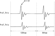
図10、及び図11にスピーカ5Lより2回のインパルス音を出力した時の収音信号PreT_Thls、PreT_Thloの波形を示す。上段が左マイク2Lによる収音信号PreT_Thls、下段が右マイク2Rによる収音信号PreT_Thloである。図10は、収音信号が重なっていない場合の信号波形を示し、図11は、収音信号が重なっている場合の信号波形を示している。図10と図11では、タップ長pを128としてインパルス音を発生させている。すなわち、128タップずれて1回目と2回目のインパルス音が発生している。
10 and 11 show waveforms of the sound pickup signals PreT_Thls and PreT_Thlo when the impulse sound is output twice from the
図10では、右マイクの収音信号の残響が少なく、収音信号が短時間で収束する。すなわち、1回目と2回目のインパルス応答が分離して測定される。よって、タップ長検出部33は、1回目の信号が収束するまでに次の信号が重なっていない(S139のNO)と判定する。この場合、さらに、タップ長を短くできる可能性がある。したがって、1回目のインパルス音の収音信号と2回目のインパルス音の収音信号とが重なっていない場合(S139のNO)、タップ長pを2で除算した値に設定する(ステップS140)。タップ長pを2で除算した後、ステップS133からの処理を繰り返す。図10ではタップ長pが128となっているため、次は、タップ長p=64としてステップS133〜ステップS139を実行する。そして、2つのインパルス音の信号が重なるまで、ステップS133〜ステップS140の処理を繰り返す。
In FIG. 10, there is little reverberation of the collected sound signal of the right microphone, and the collected sound signal converges in a short time. That is, the first and second impulse responses are measured separately. Therefore, the tap
図11では、右マイク2Rの収音信号に含まれる残響が長いため、1回目のインパルス応答測定の右マイク2Rの信号が収束するより前に、2回目のインパルス応答測定の左マイク2Lの信号が入力され、2つの信号が重なってしまう(ステップS139のYES)。タップ長検出部33が、信号が収束するまでに次の信号が重なってしまうと判定すると(ステップS139のYES)、次のステップに移行する(図8のA)。すなわち、右スピーカ5Rに対して、ステップS133〜ステップS140を繰り返す(S141)。
In FIG. 11, since the reverberation included in the collected sound signal of the
なお、1回目と2回目のインパルス音による信号が重なっているか否かは、1回目のインパルス音による収音信号と2回目のインパルス音による収音信号の相関により判定すればよい。例えば、タップ長pで収音信号を切り出すことで、1回目のインパルス音の応答と、2回目のインパルス音の応答に分離する。そして、1回目のインパルス音の応答と2回目のインパルス音の応答とを比較して、相関を求める。相関が高い場合、タップ長検出部33は、インパルス音が分離されている、すなわち、信号が重なっていないと判定する。相関が低い場合、タップ長検出部33は、インパルス音が分離されていない、すなわち、信号が重なっていると判定する。
Whether or not the signals of the first and second impulse sounds overlap each other may be determined by the correlation between the sound collection signal of the first impulse sound and the sound collection signal of the second impulse sound. For example, by extracting the collected sound signal with the tap length p, the response of the first impulse sound and the response of the second impulse sound are separated. Then, a correlation is obtained by comparing the response of the first impulse sound with the response of the second impulse sound. When the correlation is high, the tap
これにより、左右のスピーカ5L、5Rのそれぞれについて、タップ長pを求めることができる。そして、次の信号と重なる直前のタップpを最小の測定タップ長Nとする(S142)。測定タップ長Nは1以上の自然数であり、2のべき乗とすることが好ましい。例えば、次の信号と重なるタップ長が64である場合、測定タップ長Nは128(64×2)とすることが好ましい。左右のスピーカ5L、5Rで測定タップ長Nが異なる場合は、長い方の測定タップ長Nを共通のタップ長Nとすることが好ましい。そして、タップ長検出部33は、測定タップ長Nを伝達特性測定部35に出力する(図4のE)。これにより、適切な測定タップ長Nで伝達特性測定部35が伝達特性を測定することができる。
Accordingly, the tap length p can be obtained for each of the left and
(低域スレッショルド検出)
次に、図12を用いて、ステップS170の低域スレッショルド検出処理について、詳細に説明する。図12は、低域スレッショルド検出処理を示すフローチャートである。図12に示す各処理は、主として、テスト測定部31、及び低域スレッショルド検出部34が実行している。
(Low-frequency threshold detection)
Next, the low-frequency threshold detection process in step S170 will be described in detail with reference to FIG. FIG. 12 is a flowchart showing the low-frequency threshold detection process. Each process shown in FIG. 12 is mainly executed by the
まず、同期加算回数nが規定回数以上であるか否かを判定する(S171)。ここでは、同期加算回数nが規定回数未満であるため(S171のNO)、テスト測定部31は、左右のマイク2L、2Rにより、無音状態における伝達特性(第2の伝達特性)SrL、SrRを取得する(第2の環境測定)(S172)。ここで無音状態とは、スピーカ5L、5Rから音を出力していない状態である。つまり、第2の環境測定は無音状態で行われる。すなわち、マイク2L、2Rは、測定環境中でスピーカ5L、5R以外から発生している暗騒音を収音する。
First, it is determined whether or not the number n of synchronous additions is equal to or greater than a specified number (S171). Here, since the synchronous addition number n is less than the specified number (NO in S171), the
そして、テスト測定部31は、同期加算回数nをインクリメントして(S173)、ステップS171に戻る。そして、テスト測定部31は、同期加算回数nが規定回数以上となるまで、ステップS171〜ステップS173を繰り返す。スピーカ5L、5Rからの出力がない無音状態の特性SrL、SrRが規定回数分だけ測定される。例えば、同期加算回数の規定回数nは10とすることができる。
Then, the
同期加算回数nが規定回数以上となったら(S171のYES)、特性SrL、SrRをそれぞれ同期加算する(S174)。なお、同期加算は、伝達特性PreT_Thls、PreT_Thloの取得と同時に行ってもよい。すなわちステップS174は、ステップS171の後、かつステップS172の前に実施してもよい。そして、低域スレッショルド検出部34が同期加算後の特性SrL、SrRの周波数特性SrL_freq、SrR_freqを算出する(S175)。具体的には、テスト測定部31が、特性SrL、SrRを同期加算して、低域スレッショルド検出部34に出力する(図4のC)。そして、低域スレッショルド検出部34が、時間領域の特性SrLを離散フーリエ変換することで、周波数特性SrL_freqを求める。同様に、低域スレッショルド検出部34が、時間領域の特性SrRを離散フーリエ変換することで、周波数特性SrR_freqを求める。ここでは、低域スレッショルド検出部34が、FFT(高速フーリエ変換)によって、周波数特性SrL_freq、SrR_freqを求めている。もちろん、高速フーリエ変換(離散フーリエ変換)に限らず、離散コサイン変換などを用いて周波数領域に変換してもよい。
When the synchronous addition number n is equal to or greater than the prescribed number (YES in S171), the characteristics SrL and SrR are synchronously added (S174). The synchronous addition may be performed simultaneously with the acquisition of the transfer characteristics PreT_Thls and PreT_Thlo. That is, step S174 may be performed after step S171 and before step S172. Then, the low
次に、低域スレッショルド検出部34が、無音状態の周波数特性SrL_freq、SrR_freqから、低域スレッショルドthを決定する(S176)。低域スレッショルドthは、LチャンネルとRチャンネルで個別の閾値にしてもよいし、同じ閾値にしてもよい。ここで、騒音の有無による特性の違いについて、図13を用いて説明する。図13は、周波数特性を示すグラフであり、横軸が周波数(Hz)、縦軸が振幅(dB)となっている。図13において、実線が騒音無の測定環境で測定された周波数特性を示し、破線が騒音有の測定環境で測定された周波数特性を示している。騒音無は、暗騒音も少なく反射や残響を音響的に考慮した実験室で測定したデータの一例である。騒音有は、暗騒音や人の話し声を含み反射や残響を音響的に考慮していない室内で測定を行ったデータの一例である。また、図13は同一のスピーカ、同一の受聴者1において測定された周波数特性を示している。
Next, the low
図13に示すように、騒音の有無によって、800Hz以下の低域において周波数特性が大きく変化している。すなわち、騒音有の場合、低域での振幅が騒音無の場合よりも大きくなっている。これは、エアコンのコンプレッサ等によって、低域(低周波数帯域)の騒音が発生し、測定環境に影響を与えているためである。このように、低域においては暗騒音が常時発生しやすい。したがって、実際の測定環境では、低域の周波数特性を精度よく測定することが困難となる。一方、3kHz以上の高域においては、騒音の有無によって振幅に大きな違いが見られない。 As shown in FIG. 13, the frequency characteristics change greatly in the low range of 800 Hz or less depending on the presence or absence of noise. That is, when there is noise, the amplitude in the low band is larger than when there is no noise. This is because low-frequency (low-frequency band) noise is generated by an air conditioner compressor and the like, which affects the measurement environment. Thus, background noise tends to occur constantly in the low frequency range. Therefore, in an actual measurement environment, it is difficult to accurately measure the low-frequency characteristics. On the other hand, in the high range of 3 kHz or more, there is no significant difference in amplitude depending on the presence or absence of noise.
したがって、本実施の形態では、決定された低域スレッショルドthに応じて、伝達特性の補正処理を行っている。具体的には、低域スレッショルドth以下の低域(低周波数帯域)では、予め記憶された周波数特性で伝達特性を補正する。一方、低域スレッショルドthよりも高い高域(高周波数帯域)では、伝達特性測定部35での伝達特性測定により求められた周波数特性の振幅値(フィルタ値)をそのまま用いる。
Therefore, in the present embodiment, transfer characteristic correction processing is performed in accordance with the determined low-frequency threshold th. Specifically, in a low frequency (low frequency band) equal to or lower than the low frequency threshold th, the transfer characteristic is corrected with a frequency characteristic stored in advance. On the other hand, in the high band (high frequency band) higher than the low band threshold th, the amplitude value (filter value) of the frequency characteristic obtained by the transfer characteristic measurement in the transfer
具体的には、騒音の周波数帯域で、最も高い周波数を低域スレッショルドthに設定すればよい。例えば、閾値を下回る周波数(例えば800Hz)が低域スレッショルドthに設定される。すなわち、無音状態での周波数特性SrL_freq、SrL_freqを閾値と比較することで、低域スレッショルドthが設定される。周波数特性SrL_freq、SrL_freqの振幅レベルが予め設定された閾値となる周波数が低域スレッショルドthに設定される。また、低域スレッショルド検出部34は、左右の周波数特性SrL_freq、SrR_freqに対して、それぞれ低域スレッショルドthを決定する。そして、低域スレッショルド検出部34は、左右の低域スレッショルドthを低域補正部37に出力する(図4のF)。
Specifically, the highest frequency in the noise frequency band may be set to the low-frequency threshold th. For example, a frequency lower than the threshold (for example, 800 Hz) is set as the low frequency threshold th. That is, the low frequency threshold th is set by comparing the frequency characteristics SrL_freq and SrL_freq in the silent state with threshold values. The frequency at which the amplitude level of the frequency characteristics SrL_freq and SrL_freq becomes a preset threshold value is set to the low-frequency threshold th. The low
低域補正部37は、低域スレッショルドthに基づいて、伝達特性の低域を補正する。低域補正部37による補正処理については後述する。
The low
(伝達特性測定)
次に、伝達特性測定部35における伝達特性の測定処理について、図14を用い説明する。図14は、伝達特性の測定処理を示すフローチャートである。図14は、主として、左スピーカ5Lに対する処理を示している。
(Transfer characteristics measurement)
Next, transfer characteristic measurement processing in the transfer
伝達特性測定部35は、前記出力振幅レベルPgainL、PgainR、測定タップ長Nを元に、空間音響伝達特性の測定を行う。まず、伝達特性測定部35がステップS110、S130において決定した出力振幅レベルPgainL、PgainR、測定タップ長Nで初期設定する(S201)。次に、同期加算回数nが規定回数以上となっているか否かを伝達特性測定部35が判定する(S202)。ここでは、同期加算回数nが規定回数よりも小さくなっているため(S202のNO)、左スピーカ5Lが伝達特性測定用信号Sigを出力する(S203)。
The transfer
そして、伝達特性測定部35は、マイク2L、2Rによってそれぞれ特性Yhls、Yhloを取得する(S204)、同期加算回数nをインクリメントして(S205)、ステップS202に戻る。すなわち、伝達特性測定部35は、同期加算回数nが規定回数以上となるまで、ステップS202〜ステップS205を繰り返す。
Then, the transfer
そして、同期加算回数nが規定回数以上となると(S202のYES)、伝達特性測定部35がマイク2L、2Rで取得した伝達特性を同期加算する(S206)。伝達特性測定部35が同期加算後の信号の振幅レベルが規定値以上であるか否かを判定する(S207)。同期加算後の信号の振幅レベルが規定値以上でない場合(S207のNO)、表示部60がエラー出力を行うとともに(S207)、伝達特性測定部35が伝達特性Yhls、Yhloを補正処理部38に出力する(S209)。エラー出力を行うことで、受聴者1が低い測定精度での測定であることを認識することができる。エラー出力が出た場合、伝達特性測定部35は、出力振幅レベルの設定を変えて、再度伝達特性測定を行ってもよい。
When the synchronous addition number n is equal to or greater than the specified number (YES in S202), the transfer
同期加算後の信号の振幅レベルが規定値以上である場合(S207のYES)、伝達特性測定部35が特性Yhls、Yhloを補正処理部38に出力する(S209)。すなわち、同期加算後の信号を伝達特性Yhls、Yhloとして採用する。特性Yhlsは左スピーカ5Lから左マイク2Lまでの伝達特性(空間音響伝達特性)であり、特性Yhloは左スピーカ5Lから右マイク2Rまでの伝達特性(空間音響伝達特性)である。
When the amplitude level of the signal after the synchronous addition is equal to or higher than the specified value (YES in S207), the transfer
左スピーカ5Lについての測定が終了したら、伝達特性測定部35が右スピーカ5RについてもステップS202〜S208を実行する(S210)。こうすることで、伝達特性測定部35が伝達特性Yhro、伝達特性Yhrsを低域補正部37に出力する(S210)。伝達特性Yhrsは右スピーカ5Rから右マイク2Rまでの伝達特性(空間音響伝達特性)であり、伝達特性Yhroは右スピーカ5Rから左マイク2Lまでの伝達特性(空間音響伝達特性)である。
When the measurement for the
伝達特性測定部35は、伝達特性Yhls、Yhlo、Yhro、Yhrsを伝達特性として低域補正部37に出力する(図4のG)。このように伝達特性測定部35は、適切な初期設定値で伝達特性を測定することができる。すなわち、適切な出力振幅レベル、及び測定タップ長での測定を行うことができる。よって、精度よく、伝達特性を測定することができる。
The transfer
(低域補正)
次に、低域補正部37による補正処理について、図15を用いて説明する。図15はステップS300での補正処理を示すフローチャートである。図15に示す各処理は、主として、低域補正部37によって実行される。
(Low frequency correction)
Next, the correction process by the low-
まず、低域補正部37が、低域スレッショルドthを設定する(S301)。ここでは低域スレッショルド検出部34が検出した低域スレッショルドthが用いられる。次に、低域補正部37が伝達特性Yhls、Yhlo、Yhro、Yhrsの周波数特性を算出する(S302)。ここでは、伝達特性測定部35が、ステップS200で測定した伝達特性Yhls、Yhlo、Yhro、Yhrsを、低域補正部37がフーリエ変換する。こうすることで、低域補正部37が周波数特性を算出する。なお、伝達特性Yhls、Yhlo、Yhro、Yhrsの周波数特性をそれぞれfYhls、fYhlo、fYhro、fYhrsとする。ここでは、伝達特性Yhls、Yhlo、Yhro、YhrsをFFT(高速フーリエ変換)することで、周波数特性fYhls、fYhlo、fYhro、fYhrsがそれぞれ算出されている。また、フーリエ変換によって、位相特性もそれぞれ算出される。
First, the low
そして、低域補正部37が、低域スレッショルドthの以下の帯域を任意の周波数特性に置き換える(S303)。任意の周波数特性は、予め記憶部80に記憶されている。低域補正部37は、記憶部80に予め記憶されている低域補正用伝達特性の周波数特性を読み出して(図4のL)、周波数特性fYhls、fYhlo、fYhro、fYhrsを補正する。低域補正部37は、周波数特性fYhls、fYhlo、fYhro、fYhrsについて、低域スレッショルドth以下の周波数範囲のみを補正する。
Then, the low
例えば、低域スレッショルドthが800Hzの場合、前記fYhlsの800Hz以下帯域の周波数特性について、予め記憶された任意の周波数特性に置き換える。記憶部80に予め記憶された周波数特性としては、騒音のない測定環境で測定された周波数特性を用いることができる。また、受聴者1以外の第3者のユーザやダミーヘッドにおいて測定された周波数特性を用いてもよい。さらに、プリセットされた複数の周波数特性の中から、受聴者1が最適な周波数特性を選ぶようにしてもよい。ここで、周波数特性fYhls、fYhlo、fYhro、fYhrsの低域の周波数特性が置き換えられた周波数特性をそれぞれfYhls’、fYhlo’、fYhro’、fYhrs’とする。すなわち、周波数特性fYhls’、fYhlo’、fYhro’、fYhrs’は、補正後の周波数特性を示している。
For example, when the low-frequency threshold th is 800 Hz, the frequency characteristics of the fYhls band of 800 Hz or less are replaced with arbitrary frequency characteristics stored in advance. As the frequency characteristic stored in advance in the
次に、低域補正部37が、補正後の周波数特性fYhls’、fYhlo’、fYhro’、fYhrs’から時間特性を算出する(S304)。ここで、周波数特性fYhls’、fYhlo’、fYhro’、fYhrs’から算出された時間特性をそれぞれOut_hls、Out_hlo、Out_hro、Out_hrsとする。例えば、低域補正部37が逆高速フーリエ変換(IFFT)を行うことで、時間特性Out_hls、Out_hlo、Out_hro、Out_hrsを算出する。このように、逆フーリエ変換に用いられる振幅特性は、低域の周波数特性が補正された周波数特性fYhls’、fYhlo’、fYhro’、fYhrs’が用いられる。また、逆フーリエ変換に用いられる位相特性は、測定された周波数特性をそのまま用いてもよいし変更してもよい。
Next, the low
低域補正部37は、算出した時間特性を、伝達特性として頭外定位処理部10に出力する(図4のH)。そして、頭外定位処理時には、伝達特性Out_hls、Out_hlo、Out_hro、Out_hrsを用いて、頭外定位処理部10が、再生信号に対して畳み込み処理を行う。すなわち、時間特性Out_hls、Out_hlo、Out_hro、Out_hrsがそれぞれ図1に示す伝達特性Hls、Hlo、Hro、Hrsとして用いられる。時間特性Out_hls、Out_hlo、Out_hro、Out_hrsがステレオ入力信号に対して畳み込まれる。このようにすることで、適切な伝達特性を用いて頭外定位処理することができる。
The low
実施の形態2.
本実施の形態2にかかる頭外定位処理装置について、図16を用いて説明する。図16は、測定部30を示す制御ブロック図である。本実施の形態2では、タップ長検出部33がタップ長補正部36に置き換わっている。タップ長補正部36は、受聴者1によって入力されたタップ長pを補正する。そして、補正された測定タップ長Nで伝達特性測定部35が伝達特性を測定する。このようにすることで、入力されたタップ長で測定した場合に不要な反射音や残響が入る場合においても、適切なタップ長で伝達特性を測定することができる。なお、タップ長補正処理以外は、実施の形態1と同様であるため説明を省略する。例えば、出力振幅レベル判定部32、低域スレッショルド検出部34、伝達特性測定部35における処理は実施の形態1と同様である。
The out-of-head localization processing apparatus according to the second embodiment will be described with reference to FIG. FIG. 16 is a control block diagram illustrating the
タップ長補正部36は、受聴者1が入力したタップ長pが適切か否かを判定して、タップ長を補正する。図17、図18を用いてタップ長補正処理を説明する。図17、図18は、タップ長補正処理を示すフローチャートである。
The tap
まず、テスト測定部31はユーザ入力により、タップ長pを設定する(S151)。ここでは、受聴者1がタップ長pを入力すると、操作部90が、タップ長pをテスト測定部31に出力する(図16のI)。テスト測定部31は、入力されたタップ長pでテスト測定を行う。次に、環境測定用信号PreT_Sigの出力振幅レベルにPgainL、PgainRを設定する(S152)。PgainL、PgainRはステップS110で求めた出力振幅レベルである。
First, the
そして、テスト測定部31は同期加算回数nが規定回数以上であるか否かを判定する(S153)。ここでは、同期加算回数nが規定回数よりも少ないため(S153のNO)、環境測定用信号PreT_Sigを左スピーカ5Lから出力する(S154)。そして、テスト測定部31は伝達特性PreT_Thls、PreT_Thloを取得する(S155)。伝達特性PreT_Thls、PreT_Thloは、入力されたタップ長pとなっている。同期加算回数nをインクリメントして(S156)、ステップS153に戻る。同期加算回数nが規定回数以上となるまで、ステップS153〜S156の処理を繰り返す。
Then, the
同期加算回数nが規定回数以上となると(S153のYES)、伝達特性PreT_Thls、PreT_Thloを同期加算する(S157)。なお、ステップS152〜ステップS157までの処理は、ステップS132〜ステップS137と同様である。 When the synchronous addition number n is equal to or greater than the prescribed number (YES in S153), the transfer characteristics PreT_Thls and PreT_Thlo are synchronously added (S157). Note that the processing from step S152 to step S157 is the same as that from step S132 to step S137.
そして、右スピーカ5RについてステップS153〜S156を繰り返す(S158)。同期加算回数nが規定回数以上となったら、伝達特性PreT_Thro、PreT_Thrsを同期加算する(S159)。このようにして、同期加算後の伝達特性PreT_Thls、PreT_Thlo、PreT_Thro、PreT_Thrsを求めることができる。同期加算を行うことで、突発的な騒音の影響を低減することができる。
Then, steps S153 to S156 are repeated for the
次に、伝達特性PreT_Thlsと伝達特性PreT_Thrsとの切り出し位置を合わせる(S160)。例えば、タップ長補正部36は、直接音側のピーク(極大値)位置が一致するように、波形をシフトさせる。すなわち、伝達特性PreT_Thlsのピーク(極大値)位置と伝達特性PreT_Thrsのピーク(極大値)位置が同じサンプル位置になるように、波形をシフトさせる。そして、タップ長補正部36は、切り出し位置を合わせた後の伝達特性PreT_Thlo、PreT_Throの収束位置を解析する(S161)。ここでは、タップ長補正部36が伝達特性PreT_Thlo、PreT_Throの収束位置をそれぞれ求める。例えば、ステップS138と同様に、タップ長補正部36は、ピークの5%以内に収まるサンプル位置を収束位置とする。
Next, the cut-out positions of the transfer characteristic PreT_Thls and the transfer characteristic PreT_Thrs are matched (S160). For example, the tap
そして、伝達特性PreT_Thlo、PreT_Throの収束位置が、ステップS151で設定したタップ長pよりも大きいか否かを判定する(S162)。収束位置がタップ長pよりも大きい場合(S162のYES)、エラー終了又はリトライする(S163)。すなわち、収束位置がタップ長pよりも長い場合、入力されたタップ長pでは、適切に伝達特性を測定できないため、タップ長をp入力した受聴者1にエラーが生じることを報知する。あるいは、タップ長pを長くして、再度、タップ長補正処理を行う。 Then, it is determined whether or not the convergence positions of the transfer characteristics PreT_Thlo and PreT_Thro are larger than the tap length p set in step S151 (S162). When the convergence position is larger than the tap length p (YES in S162), the process ends or retries (S163). That is, when the convergence position is longer than the tap length p, the transfer characteristic cannot be measured appropriately with the input tap length p, so that an error occurs to the listener 1 who has input the tap length p. Alternatively, the tap length p is increased and the tap length correction process is performed again.
一方、収束位置がタップ長pよりも小さい場合(S162のNO)、伝達特性PreT_Thlo、PreT_Throの収束位置が収まる最小のタップ長を測定タップ長Nに決定する(S164)、タップ長補正部36は、測定タップ長Nを伝達特性測定部35に出力する(図16のE)。測定タップ長Nは、2のべき乗とすることが好ましい。例えば、収束位置が510タップの場合、測定タップ長N=512とする。伝達特性測定部35は、特定タップ長Nで、伝達特性を測定する。このようにすることで、適切な測定タップ長Nで伝達特性を測定することができる。
On the other hand, when the convergence position is smaller than the tap length p (NO in S162), the minimum tap length within which the convergence positions of the transfer characteristics PreT_Thlo and PreT_Thro fall is determined as the measurement tap length N (S164), the tap
実施の形態3.
本実施の形態では、補正処理部38にタップ長補正部36が設けられている。タップ長補正部36は、実施の形態2のタップ長補正部36と同様にタップ長を補正する。また、本実施の形態では、伝達特性測定部35が測定した特性をタップ長補正部36に出力する。そして、タップ長補正部36は、伝達特性測定部35が測定した伝達特性に対して、タップ長補正を行っている。
Embodiment 3 FIG.
In the present embodiment, the
操作部90は、受聴者1の入力によるタップ長pを伝達特性測定部35に出力する(図19のK)。伝達特性測定部35は、受聴者1が入力したタップ長pによって伝達特性を測定する。そして、タップ長補正部36は、伝達特性を測定したタップ長が適切か否かを判定して、タップ長を補正する。具体的には、タップ長補正部36は、図17、図18で示したフローにしたがってタップ長補正を行う。ただし、ここでは、タップ長補正部36は、伝達特性測定部35が測定した伝達特性Hls、Hlo、Hro、Hrsに対して、タップ長補正を行う。そして、タップ長補正部36は、伝達特性Hlo、Hroの収束位置が収まるタップ長を測定タップ長Nとして決定する。
The
タップ長補正部36は、伝達特性から測定タップ長のNサンプル分だけ切り出す処理を行う。すなわち、受聴者1が予め長いタップ長pを入力しておき、タップ長補正部36は、測定タップ長のNサンプル分だけ伝達特性から一部を切り出す。
The tap
図20を用いて補正処理部38における補正処理を説明する。図20は、補正処理部38における補正処理を示すフローチャートである。まず、タップ長補正部36が、伝達特性に対して、タップ長補正処理を行う(S310)。そして、タップ長補正処理が行われた伝達特性に対して、低域補正部37が低域補正処理を行う(S320)。低域補正処理は、図15で示した処理と同様である。
The correction process in the
次に、タップ長補正処理の詳細について、図21、図22を用いて説明する、図21は、タップ長補正処理を示すフローチャートである。図22は、タップ長補正処理での時間領域の信号波形(伝達特性)の切り出し方を模式的に示す図である。 Next, details of the tap length correction process will be described with reference to FIGS. 21 and 22. FIG. 21 is a flowchart showing the tap length correction process. FIG. 22 is a diagram schematically illustrating how to cut out a signal waveform (transfer characteristic) in the time domain in the tap length correction process.
まず、伝達特性測定部35が測定した伝達特性Yhls、Yhrsの切り出し位置を合わせる(S311)。ここでは、図22に示すように、伝達特性Yhlsのピーク(極大値)位置と、伝達特性Yhrsのピーク(極大値)位置が同じサンプル位置になるように波形をシフトさせて波形の切り出し位置を調整する。切り出し位置が調整された伝達特性Yhls、Yhloを伝達特性Yhls’’、Yhlo’’として示している。
First, the cutout positions of the transfer characteristics Yhls and Yhrs measured by the transfer
次に、伝達特性Yhls、Yhrsを先頭から測定タップ長のNサンプル分だけ切り出す(S312)。例えば、先頭から512タップ分の伝達特性を切り出す。なお、切り出すタップ長は、2のべき乗となっていることが好ましい。図22のように、測定タップ長のNサンプル分だけ切り出された後の伝達特性を伝達特性Yd_hls、Yd_hlo、Yd_hro、Yd_hrsとする。切り出された伝達特性Yd_hls、Yd_hlo、Yd_hro、Yd_hrsは、それぞれN個のデジタル値から構成されている。 Next, transfer characteristics Yhls and Yhrs are cut out from the head by N samples of the measurement tap length (S312). For example, transfer characteristics for 512 taps are cut out from the top. The tap length to be cut out is preferably a power of 2. As shown in FIG. 22, the transfer characteristics after cutting out N samples of the measurement tap length are set as transfer characteristics Yd_hls, Yd_hlo, Yd_hro, and Yd_hrs. The extracted transfer characteristics Yd_hls, Yd_hlo, Yd_hro, and Yd_hrs are each composed of N digital values.
そして、切り出された伝達特性Yd_hls、Yd_hlo、Yd_hro、Yd_hrsを窓関数で処理する(S313)。すなわち、切り出された伝達特性Yd_hls、Yd_hlo、Yd_hro、Yd_hrsに窓関数の係数を乗じる。タップ長補正部36は、測定タップ長のNサンプルに切り出した伝達特性Yd_hls、Yd_hlo、Yd_hro、Yd_hrsを、低域補正部37に出力する(S314)。そして、低域補正部37は、上記のように低域のフィルタ値を補正する。
Then, the cut out transfer characteristics Yd_hls, Yd_hlo, Yd_hro, Yd_hrs are processed with a window function (S313). That is, the clipped transfer characteristics Yd_hls, Yd_hlo, Yd_hro, and Yd_hrs are multiplied by a window function coefficient. The tap
このようにすることで、適切なタップ数(サンプリング数)の伝達特性を取得することができる。よって、頭外定位処理部10が適切に頭外定位処理することができる。
In this way, it is possible to acquire transfer characteristics with an appropriate number of taps (sampling number). Therefore, the out-of-head
実施の形態4.
本実施の形態にかかる頭外定位処理装置100について図23を用いて説明する。図23は、本実施の形態にかかる頭外定位処理装置100の測定部30の構成を示す制御ブロック図である。本実施の形態では、低域スレッショルド検出部34が暗騒音検出部50に置き換わっている。さらに、低域補正部37による処理が実施の形態1と異なっている。なお、暗騒音検出部50、及び低域補正部37以外の処理については実施の形態1と同様であるため、説明を省略する。
Embodiment 4 FIG.
The out-of-head
暗騒音検出部50と低域補正部37での処理について、図24を用いて説明する。図24は、暗騒音検出部50と低域補正部37での処理を示すフローチャートである。
Processing in the background
まず、暗騒音検出部50が同期加算によって伝達特性測定用信号を出力しない無音状態の伝達特性SrL、SrRを取得する。ここで取得した伝達特性SrL、SrRには、暗騒音を含む測定環境特有の信号を取得することができる。暗騒音検出部50は、同期加算回数nが規定回数以上であるか否かを判定する(S171)。ここでは、同期加算回数nが規定回数未満であるため(S171のNO)、左右のマイク2L、2Rが無音状態との伝達特性SrL、SrRを取得する(S172)。同期加算回数nをインクリメントして(S173)、ステップS171に戻る。同期加算回数nが規定回数以上となるまで、ステップS171〜ステップS173を繰り返す。
First, the background
同期加算回数nが規定回数以上となったら(S171のYES)、伝達特性SrL、SrRをそれぞれ同期加算する(S174)。ここまでは、図12と同様である。そして、伝達特性Yhls〜Yhrsから無音状態の伝達特性SrL、SrRを減算して、Out_hls〜Out_Hrsを算出する(S177)。 When the synchronous addition number n is equal to or greater than the predetermined number (YES in S171), the transfer characteristics SrL and SrR are synchronously added (S174). Up to this point, the process is the same as in FIG. Then, the transmission characteristics SrL and SrR in silence are subtracted from the transmission characteristics Yhls to Yhrs to calculate Out_hls to Out_Hrs (S177).
具体的には、暗騒音検出部50は、無音状態での伝達特性SrL、SrRを暗騒音として、低域補正部37に出力する(図23のM)。伝達特性測定部35は、伝達特性Yhls、Yhlo、Yhro、Yhrsを低域補正部37に出力する(図23のG)。なお、伝達特性Yhls、Yhlo、Yhro、Yhrsと、無音状態の伝達特性SrL、SrRを同じ回数だけ同期加算されている。
Specifically, the background
伝達特性Outhls=Yhls−SrLとなり、伝達特性Outhro=Yhro−SrLとなる。また、伝達特性Outhlo=Yhlo−SrRとなり、伝達特性Outhrs=Yhrs−SrRとなる。このように、補正処理部38は、測定した伝達特性Yhls〜Yhrsから暗騒音となる無音状態の伝達特性SrL、SrRを減算する。
The transfer characteristic Authls = Yhls−SrL, and the transfer characteristic Authhro = Yhro−SrL. Further, the transfer characteristic Othlo = Yhlo-SrR, and the transfer characteristic Othrs = Yhrs-SrR. In this way, the
無音状態であっても低域には暗騒音が存在している。よって、測定された伝達特性Yhls〜Yhrsから無音状態の伝達特性SrL、SrRを減算することで、低域を補正することができる。すなわち、伝達特性Outhls〜Outhrsでは、低域における暗騒音の影響が軽減されている。このようにすることで、暗騒音の影響が軽減された伝達特性を求めることができる。そして、低域が補正された伝達特性を用いて、頭外定位処理部10が畳み込み処理を行う。これにより、適切に頭外定位処理することができる。
Even in the silent state, background noise exists in the low frequency range. Therefore, the low frequency range can be corrected by subtracting the silent transmission characteristics SrL and SrR from the measured transmission characteristics Yhls to Yhrs. That is, in the transfer characteristics Outhls to Outthrs, the influence of the background noise in the low range is reduced. By doing so, it is possible to obtain a transfer characteristic in which the influence of background noise is reduced. Then, the out-of-head
なお、上記した実施の形態1〜4は適宜組み合わせることが可能である。例えば、実施の形態4による低域補正は、実施の形態2又は実施の形態3と組み合わせてもよい。また、上記の実施の形態1〜4において、各処理や各測定の順番は特に限定されるものではない。例えば、無音状態での測定を伝達特性の測定よりも後に行ってもよい。 Note that Embodiments 1 to 4 described above can be combined as appropriate. For example, the low frequency correction according to the fourth embodiment may be combined with the second embodiment or the third embodiment. Moreover, in said Embodiment 1-4, the order of each process and each measurement is not specifically limited. For example, the measurement in the silent state may be performed after the measurement of the transfer characteristic.
上記したように実施の形態1〜4では、頭外定位処理装置100が左右のスピーカ5L、5Rと、左右のスピーカ5L、5Rで出力された音を収音する左右のマイク2L、2Rと、伝達特性を測定する伝達特性測定部35と、伝達特性を用いて再生信号に対して頭外定位処理を行って、左右のスピーカに出力する頭外定位処理部10と、環境測定部39と、を備えている。伝達特性測定部35は、左右のスピーカ5L、5Rから出力された伝達特性測定用信号を左右のマイク2L、2Rで収音することで、左右のスピーカ5L、5Rから左右のマイク2L、2Rまでの伝達特性をそれぞれ測定する。
As described above, in the first to fourth embodiments, the out-of-head
そして、環境測定部39が、左右のスピーカ5L、5Rから出力された環境測定用信号を左右のマイク2L、2Rで収音することで、伝達特性測定用信号を設定するための環境測定を行う。環境測定部39での測定結果に基づいて、伝達特性測定用信号の出力振幅レベルと、伝達特性のタップ長と、が設定される。環境測定部39が左右のスピーカから測定用信号を出力していない無音状態での測定を行い、無音状態での測定結果に基づいて、伝達特性測定部35で測定された伝達特性の低域が補正されている。
The
このようにすることで、適切な伝達特性を求めることができるため、頭外定位処理を適切に行うことができる。すなわち、適切な測定タップ長、及び適切な出力振幅レベルで伝達特性を測定することができる。さらに、無音状態の伝達特性により、伝達特性の低周波数帯域が補正されている。よって、伝達特性から暗騒音の影響を軽減することができる。これにより、適切な伝達特性を用いた畳み込み処理が可能となる。 By doing in this way, since an appropriate transfer characteristic can be calculated | required, an out-of-head localization process can be performed appropriately. That is, the transfer characteristic can be measured with an appropriate measurement tap length and an appropriate output amplitude level. Furthermore, the low frequency band of the transfer characteristic is corrected by the transfer characteristic in the silent state. Therefore, the influence of background noise can be reduced from the transfer characteristics. Thereby, a convolution process using an appropriate transfer characteristic is possible.
また、実施の形態1〜3では、無音状態での測定結果に基づいて、低域スレッショルドが設定されている。そして、低域スレッショルドよりも低い低域では、伝達特性のフィルタ値が補正され、低域スレッショルドよりも高い高域では、伝達特性測定部で測定された伝達特性のフィルタ値がそのまま用いられている。このようにすることで、簡便かつ適切に伝達特性を補正することができる。さらに、低域スレッショルドよりも低い低域では、伝達特性のフィルタ値が記憶部80に予め記憶されているフィルタ値に置き換えられる。これにより、簡便に伝達特性を補正することができる。
In the first to third embodiments, the low frequency threshold is set based on the measurement result in the silent state. Then, the transfer characteristic filter value is corrected at a low frequency lower than the low frequency threshold, and the transfer characteristic filter value measured by the transfer characteristic measuring unit is used as it is at a high frequency higher than the low frequency threshold. . By doing in this way, a transfer characteristic can be corrected simply and appropriately. Further, at a low frequency lower than the low frequency threshold, the filter value of the transfer characteristic is replaced with a filter value stored in advance in the
実施の形態4では、伝達特性測定部35で測定された伝達特性から、無音状態で測定された伝達特性を減じることで、伝達特性を補正している。これにより、伝達特性から暗騒音の影響を軽減することができる。これにより、適切な伝達特性を用いた畳み込み処理が可能となる。
In the fourth embodiment, the transfer characteristic is corrected by subtracting the transfer characteristic measured in the silent state from the transfer characteristic measured by the transfer
また、実施の形態1、2では、伝達特性の測定タップ長が、左右のマイクで収音された環境測定用信号の収束時間に基づいて設定されている。このようにすることで、適切なタップ長で伝達特性を求めることができる。 In the first and second embodiments, the transfer characteristic measurement tap length is set based on the convergence time of the environment measurement signal collected by the left and right microphones. By doing in this way, a transfer characteristic can be calculated | required by appropriate tap length.
なお、上記の実施形態1〜4では、音像定位処理装置として、ヘッドホンを用いて頭外に音像を定位する頭外定位処理装置について説明したが、本実施の形態は頭外定位処理装置に限られるものではない。例えば、スピーカ5L、5Rからステレオ信号を再生することで、音像を定位させる音像定位処理装置に用いてもよい。すなわち、本実施の形態は、伝達特性を再生信号に畳み込む音像定位処理装置にて適用することが可能になる。
In the first to fourth embodiments described above, an out-of-head localization processing apparatus that localizes a sound image using headphones as a sound image localization processing apparatus has been described. However, this embodiment is limited to an out-of-head localization processing apparatus. It is not something that can be done. For example, it may be used for a sound image localization processing device that localizes a sound image by reproducing stereo signals from the
上記信号処理のうちの一部又は全部は、コンピュータプログラムによって実行されてもよい。上述したプログラムは、様々なタイプの非一時的なコンピュータ可読媒体(non−transitory computer readable medium)を用いて格納され、コンピュータに供給することができる。非一時的なコンピュータ可読媒体は、様々なタイプの実体のある記録媒体(tangible storage medium)を含む。非一時的なコンピュータ可読媒体の例は、磁気記録媒体(例えばフレキシブルディスク、磁気テープ、ハードディスクドライブ)、光磁気記録媒体(例えば光磁気ディスク)、CD−ROM(Read Only Memory)、CD−R、CD−R/W、半導体メモリ(例えば、マスクROM、PROM(Programmable ROM)、EPROM(Erasable PROM)、フラッシュROM、RAM(Random Access Memory))を含む。また、プログラムは、様々なタイプの一時的なコンピュータ可読媒体(transitory computer readable medium)によってコンピュータに供給されてもよい。一時的なコンピュータ可読媒体の例は、電気信号、光信号、及び電磁波を含む。一時的なコンピュータ可読媒体は、電線及び光ファイバ等の有線通信路、又は無線通信路を介して、プログラムをコンピュータに供給できる。 Part or all of the signal processing may be executed by a computer program. The programs described above can be stored and provided to a computer using various types of non-transitory computer readable media. Non-transitory computer readable media include various types of tangible storage media. Examples of non-transitory computer-readable media include magnetic recording media (for example, flexible disks, magnetic tapes, hard disk drives), magneto-optical recording media (for example, magneto-optical disks), CD-ROMs (Read Only Memory), CD-Rs, CD-R / W, semiconductor memory (for example, mask ROM, PROM (Programmable ROM), EPROM (Erasable PROM), flash ROM, RAM (Random Access Memory)). The program may also be supplied to the computer by various types of transitory computer readable media. Examples of transitory computer readable media include electrical signals, optical signals, and electromagnetic waves. The temporary computer-readable medium can supply the program to the computer via a wired communication path such as an electric wire and an optical fiber, or a wireless communication path.
以上、本発明者によってなされた発明を実施の形態に基づき具体的に説明したが、本発明は上記実施の形態に限られたものではなく、その要旨を逸脱しない範囲で種々変更可能であることは言うまでもない。 As mentioned above, the invention made by the present inventor has been specifically described based on the embodiment. However, the present invention is not limited to the above embodiment, and various modifications can be made without departing from the scope of the invention. Needless to say.
U ユーザ
1 受聴者
2L 左マイク
2R 右マイク
3L 増幅器
3R 増幅器
4L A/D変換器
4R A/D変換器
5L 左スピーカ
5R 右スピーカ
6L 増幅器
6R 増幅器
7L D/A変換器
7R D/A変換器
9L 左耳
9R 右耳
10 頭外定位処理部
11 畳み込み演算部
12 畳み込み演算部
21 畳み込み演算部
22 畳み込み演算部
24 加算器
25 加算器
30 測定部
31 テスト測定部
32 出力振幅レベル判定部
33 タップ長検出部
34 低域スレッショルド検出部
35 伝達特性測定部
36 タップ長補正部
37 低域補正部
38 補正処理部
39 環境測定部
41 フィルタ部
42 フィルタ部
43 ヘッドホン
50 暗騒音検出部
60 表示部
70 入力部
80 記憶部
90 操作部
100 頭外定位処理装置
200 測定装置
U user 1
Claims (10)
左右のマイクと、
前記左右のスピーカから出力された伝達特性測定用信号を前記左右のマイクで収音することで、前記左右のスピーカから前記左右のマイクまでの第1の伝達特性をそれぞれ測定する伝達特性測定部と、
前記第1の伝達特性を用いて再生信号に対して畳み込み演算を行う畳み込み演算部と、
前記左右のスピーカから出力された環境測定用信号を前記左右のマイクで収音する第1の環境測定と、前記左右のスピーカから音を出力していない状態において前記左右のマイクで収音する第2の環境測定とを行い、前記第1の環境測定の結果に基づいて、前記伝達特性測定用信号の振幅レベルと、前記第1の伝達特性のタップ長とを設定し、前記第2の環境測定の結果に基づいて、第2の伝達特性を測定する環境測定部と、
前記第2の伝達特性に基づいて、前記第1の伝達特性の低域を補正する補正処理部と、
を備える音像定位処理装置。 Left and right speakers,
Left and right microphones,
A transfer characteristic measurement unit that measures first transfer characteristics from the left and right speakers to the left and right microphones by collecting the transfer characteristic measurement signals output from the left and right speakers with the left and right microphones; ,
A convolution operation unit that performs a convolution operation on the reproduction signal using the first transfer characteristic;
First environment measurement for collecting environment measurement signals output from the left and right speakers with the left and right microphones, and first sound collection with the left and right microphones in a state where no sound is output from the left and right speakers. 2, and setting the amplitude level of the transfer characteristic measurement signal and the tap length of the first transfer characteristic based on the result of the first environment measurement, and the second environment An environment measurement unit for measuring the second transfer characteristic based on the measurement result;
A correction processing unit that corrects a low frequency range of the first transfer characteristic based on the second transfer characteristic;
A sound image localization processing apparatus.
前記補正処理部は、前記閾値よりも低い周波数帯域では、前記第1の伝達特性を補正し、前記閾値よりも高い周波数帯域では、前記第1の伝達特性を用いる請求項1に記載の音像定位処理装置。 The environment measurement unit sets a frequency threshold of the first transfer characteristic based on the second transfer characteristic,
The sound image localization according to claim 1, wherein the correction processing unit corrects the first transfer characteristic in a frequency band lower than the threshold, and uses the first transfer characteristic in a frequency band higher than the threshold. Processing equipment.
前記左右のスピーカから出力された環境測定用信号を前記左右のマイクで収音する第1の環境測定と、前記左右のスピーカから音を出力していない状態において前記左右のマイクで収音する第2の環境測定とを行い、前記第1の環境測定の結果に基づいて、伝達特性測定用信号の振幅レベルと、前記左右のスピーカから前記左右のマイクまでの前記第1の伝達特性のタップ長とを設定し、前記第2の環境測定の結果に基づいて、第2の伝達特性を測定する環境測定ステップと、
前記第1の環境測定の結果に基づいて設定された前記伝達特性測定用信号を前記左右のスピーカから出力し、前記伝達特性測定用信号を前記左右のマイクで収音することで、前記第1の伝達特性をそれぞれ測定する伝達特性測定ステップと、
前記第2の伝達特性に基づいて、前記第1の伝達特性の低域を補正する補正ステップと、を含む音像定位処理方法。 A sound image localization processing method for performing sound image localization processing using a first transfer characteristic between left and right speakers and left and right microphones,
First environment measurement for collecting environment measurement signals output from the left and right speakers with the left and right microphones, and first sound collection with the left and right microphones in a state where no sound is output from the left and right speakers. 2, and based on the result of the first environmental measurement, the amplitude level of the transfer characteristic measurement signal and the tap length of the first transfer characteristic from the left and right speakers to the left and right microphones And an environmental measurement step of measuring the second transfer characteristic based on the result of the second environmental measurement;
The transfer characteristic measurement signal set based on the result of the first environment measurement is output from the left and right speakers, and the transfer characteristic measurement signal is picked up by the left and right microphones. A transfer characteristic measuring step for measuring the transfer characteristics of
A sound image localization processing method comprising: a correction step of correcting a low frequency range of the first transfer characteristic based on the second transfer characteristic.
前記補正ステップでは、
前記閾値よりも低い周波数帯域では、前記第1の伝達特性が補正され、
前記閾値よりも高い周波数帯域では、前記第1の伝達特性を用いる請求項6に記載の音像定位処理方法。 In the environment measurement step, a frequency threshold value of the first transfer characteristic is set based on the second transfer characteristic,
In the correction step,
In the frequency band lower than the threshold, the first transfer characteristic is corrected,
The sound image localization processing method according to claim 6, wherein the first transfer characteristic is used in a frequency band higher than the threshold value.
Priority Applications (5)
| Application Number | Priority Date | Filing Date | Title |
|---|---|---|---|
| JP2016012043A JP6565709B2 (en) | 2016-01-26 | 2016-01-26 | Sound image localization processing apparatus and sound image localization processing method |
| PCT/JP2016/004901 WO2017130255A1 (en) | 2016-01-26 | 2016-11-16 | Audio image localization processing device and audio image localization processing method |
| EP16887844.5A EP3410746B1 (en) | 2016-01-26 | 2016-11-16 | Audio image localization processing device and audio image localization processing method |
| CN201680079526.0A CN108476372B (en) | 2016-01-26 | 2016-11-16 | Measuring device and measuring method |
| US16/044,366 US10375507B2 (en) | 2016-01-26 | 2018-07-24 | Measurement device and measurement method |
Applications Claiming Priority (1)
| Application Number | Priority Date | Filing Date | Title |
|---|---|---|---|
| JP2016012043A JP6565709B2 (en) | 2016-01-26 | 2016-01-26 | Sound image localization processing apparatus and sound image localization processing method |
Publications (2)
| Publication Number | Publication Date |
|---|---|
| JP2017135486A true JP2017135486A (en) | 2017-08-03 |
| JP6565709B2 JP6565709B2 (en) | 2019-08-28 |
Family
ID=59397580
Family Applications (1)
| Application Number | Title | Priority Date | Filing Date |
|---|---|---|---|
| JP2016012043A Active JP6565709B2 (en) | 2016-01-26 | 2016-01-26 | Sound image localization processing apparatus and sound image localization processing method |
Country Status (5)
| Country | Link |
|---|---|
| US (1) | US10375507B2 (en) |
| EP (1) | EP3410746B1 (en) |
| JP (1) | JP6565709B2 (en) |
| CN (1) | CN108476372B (en) |
| WO (1) | WO2017130255A1 (en) |
Cited By (2)
| Publication number | Priority date | Publication date | Assignee | Title |
|---|---|---|---|---|
| JPWO2023228900A1 (en) * | 2022-05-26 | 2023-11-30 | ||
| JPWO2024024053A1 (en) * | 2022-07-28 | 2024-02-01 |
Families Citing this family (3)
| Publication number | Priority date | Publication date | Assignee | Title |
|---|---|---|---|---|
| DE112019004139T5 (en) | 2018-08-17 | 2021-05-06 | Sony Corporation | SIGNAL PROCESSING DEVICE, SIGNAL PROCESSING METHOD AND PROGRAM |
| CN109246573B (en) * | 2018-10-08 | 2020-10-27 | 北京铸声场传媒科技有限公司 | Method and device for measuring frequency response characteristic of audio system |
| JP7435334B2 (en) * | 2020-07-20 | 2024-02-21 | 株式会社Jvcケンウッド | Extra-head localization filter determination system, extra-head localization filter determination method, and program |
Family Cites Families (5)
| Publication number | Priority date | Publication date | Assignee | Title |
|---|---|---|---|---|
| JP2870440B2 (en) * | 1995-02-14 | 1999-03-17 | 日本電気株式会社 | Three-dimensional sound field reproduction method |
| JP2002135898A (en) | 2000-10-19 | 2002-05-10 | Matsushita Electric Ind Co Ltd | Sound image localization control headphones |
| JP3435141B2 (en) | 2001-01-09 | 2003-08-11 | 松下電器産業株式会社 | SOUND IMAGE LOCALIZATION DEVICE, CONFERENCE DEVICE USING SOUND IMAGE LOCALIZATION DEVICE, MOBILE PHONE, AUDIO REPRODUCTION DEVICE, AUDIO RECORDING DEVICE, INFORMATION TERMINAL DEVICE, GAME MACHINE, COMMUNICATION AND BROADCASTING SYSTEM |
| US20060056638A1 (en) * | 2002-09-23 | 2006-03-16 | Koninklijke Philips Electronics, N.V. | Sound reproduction system, program and data carrier |
| JP4780119B2 (en) * | 2008-02-15 | 2011-09-28 | ソニー株式会社 | Head-related transfer function measurement method, head-related transfer function convolution method, and head-related transfer function convolution device |
-
2016
- 2016-01-26 JP JP2016012043A patent/JP6565709B2/en active Active
- 2016-11-16 CN CN201680079526.0A patent/CN108476372B/en active Active
- 2016-11-16 EP EP16887844.5A patent/EP3410746B1/en active Active
- 2016-11-16 WO PCT/JP2016/004901 patent/WO2017130255A1/en not_active Ceased
-
2018
- 2018-07-24 US US16/044,366 patent/US10375507B2/en active Active
Cited By (4)
| Publication number | Priority date | Publication date | Assignee | Title |
|---|---|---|---|---|
| JPWO2023228900A1 (en) * | 2022-05-26 | 2023-11-30 | ||
| WO2023228900A1 (en) * | 2022-05-26 | 2023-11-30 | クレプシードラ株式会社 | Signal processing system, signal processing method, and program |
| JPWO2024024053A1 (en) * | 2022-07-28 | 2024-02-01 | ||
| JP7740558B2 (en) | 2022-07-28 | 2025-09-17 | Ntt株式会社 | Transfer characteristic correction device, transfer characteristic correction method, and program |
Also Published As
| Publication number | Publication date |
|---|---|
| JP6565709B2 (en) | 2019-08-28 |
| WO2017130255A1 (en) | 2017-08-03 |
| EP3410746A1 (en) | 2018-12-05 |
| EP3410746A4 (en) | 2019-01-23 |
| CN108476372B (en) | 2020-10-09 |
| US10375507B2 (en) | 2019-08-06 |
| US20180332426A1 (en) | 2018-11-15 |
| EP3410746B1 (en) | 2021-06-02 |
| CN108476372A (en) | 2018-08-31 |
Similar Documents
| Publication | Publication Date | Title |
|---|---|---|
| US10264387B2 (en) | Out-of-head localization processing apparatus and out-of-head localization processing method | |
| US11115743B2 (en) | Signal processing device, signal processing method, and program | |
| JP6565709B2 (en) | Sound image localization processing apparatus and sound image localization processing method | |
| JP2017532816A (en) | Audio reproduction system and method | |
| JP6701824B2 (en) | Measuring device, filter generating device, measuring method, and filter generating method | |
| JP6950405B2 (en) | Processing equipment, processing methods, and programs | |
| US10779107B2 (en) | Out-of-head localization device, out-of-head localization method, and out-of-head localization program | |
| CN110301142B (en) | Filter generation device, filter generation method, and storage medium | |
| US10687144B2 (en) | Filter generation device and filter generation method | |
| CN108605197B (en) | Filter generation device, filter generation method, and sound image localization processing method | |
| JP6805879B2 (en) | Filter generator, filter generator, and program | |
| US12096194B2 (en) | Processing device, processing method, filter generation method, reproducing method, and computer readable medium | |
| JP7639607B2 (en) | Processing device and processing method | |
| JP6988321B2 (en) | Signal processing equipment, signal processing methods, and programs | |
| JP2019062265A (en) | Signal processing apparatus, signal processing method, and program | |
| JP2024164882A (en) | AGC control device, AGC control method, and program |
Legal Events
| Date | Code | Title | Description |
|---|---|---|---|
| A621 | Written request for application examination |
Free format text: JAPANESE INTERMEDIATE CODE: A621 Effective date: 20181207 |
|
| TRDD | Decision of grant or rejection written | ||
| A01 | Written decision to grant a patent or to grant a registration (utility model) |
Free format text: JAPANESE INTERMEDIATE CODE: A01 Effective date: 20190702 |
|
| A61 | First payment of annual fees (during grant procedure) |
Free format text: JAPANESE INTERMEDIATE CODE: A61 Effective date: 20190715 |
|
| R150 | Certificate of patent or registration of utility model |
Ref document number: 6565709 Country of ref document: JP Free format text: JAPANESE INTERMEDIATE CODE: R150 |