JP2017136251A - Ultrasonic imaging apparatus and ultrasonic imaging method - Google Patents

Ultrasonic imaging apparatus and ultrasonic imaging method Download PDF

Info

Publication number
JP2017136251A
JP2017136251A JP2016020059A JP2016020059A JP2017136251A JP 2017136251 A JP2017136251 A JP 2017136251A JP 2016020059 A JP2016020059 A JP 2016020059A JP 2016020059 A JP2016020059 A JP 2016020059A JP 2017136251 A JP2017136251 A JP 2017136251A
Authority
JP
Japan
Prior art keywords
ultrasonic
transmission
reception
imaging
imaging apparatus
Prior art date
Legal status (The legal status is an assumption and is not a legal conclusion. Google has not performed a legal analysis and makes no representation as to the accuracy of the status listed.)
Granted
Application number
JP2016020059A
Other languages
Japanese (ja)
Other versions
JP6595360B2 (en
Inventor
千鶴枝 田中
Chizue Tanaka
千鶴枝 田中
貞一郎 池田
Teiichiro Ikeda
貞一郎 池田
Current Assignee (The listed assignees may be inaccurate. Google has not performed a legal analysis and makes no representation or warranty as to the accuracy of the list.)
Hitachi Ltd
Original Assignee
Hitachi Ltd
Priority date (The priority date is an assumption and is not a legal conclusion. Google has not performed a legal analysis and makes no representation as to the accuracy of the date listed.)
Filing date
Publication date
Application filed by Hitachi Ltd filed Critical Hitachi Ltd
Priority to JP2016020059A priority Critical patent/JP6595360B2/en
Publication of JP2017136251A publication Critical patent/JP2017136251A/en
Application granted granted Critical
Publication of JP6595360B2 publication Critical patent/JP6595360B2/en
Active legal-status Critical Current
Anticipated expiration legal-status Critical

Links

Images

Landscapes

  • Ultra Sonic Daignosis Equipment (AREA)

Abstract

PROBLEM TO BE SOLVED: To provide a method for acquiring an effect of high picture quality by aperture synthesis even when an imaging object moves.SOLUTION: An ultrasonic wave is transmitted to a range 33 which should be imaged of an imaging object 20 from a transmission opening 110 of an ultrasonic probe 108. An echo of the ultrasonic wave from the imaging object 20 is received by a reception area 130 of the ultrasonic probe, then phasing processing is performed on an output of the reception area 130, and acquiring a reception signal on a desired reception focus of the imaging object 20. A plurality of reception signals for a same reception focus are subjected to addition processing, the plurality of reception signals being acquired by a reception part 105 from the echoes of the ultrasonics transmitted at different transmission timings and from different transmission apertures 111. At this time, when the ultrasonics are transmitted, the ultrasonics are sequentially transmitted from the different plurality of transmission apertures 110, 111 at timings in which, a spatial position of the reception focus on the imaging object 20 matches according to movement of the imaging object 20 with respect to a same area out of the plurality of areas obtained by dividing the range 33 which should be imaged of the imaging object 20.SELECTED DRAWING: Figure 1

Description

本発明は、超音波撮像装置において送信間合成を行うことによって、高画質な撮像を行う技術に関するものである。   The present invention relates to a technique for performing high-quality imaging by performing transmission-to-transmission synthesis in an ultrasonic imaging apparatus.

超音波を用いた撮像装置は、超音波を対象物に送信し、対象物で反射したエコーを電気信号として受信し、受信信号を画像データとしてモニター上に表示することで構成される。超音波は、装置に備えられた超音波振動子(トランスデューサ)に電気信号を入力することで生成される。エコーは、超音波振動子によって受信されることで電気的な受信信号に変換される。撮像装置は、受信信号の強度を断層像や立体像として表示することで、撮像対象の内部構造を描写する。このような撮像技術は、生体の断層像を低侵襲で撮像する診断装置などとして、広く用いられている。   An imaging apparatus using ultrasonic waves is configured by transmitting ultrasonic waves to an object, receiving an echo reflected by the object as an electrical signal, and displaying the received signal on a monitor as image data. Ultrasound is generated by inputting an electrical signal to an ultrasonic transducer (transducer) provided in the apparatus. The echo is converted into an electrical reception signal by being received by the ultrasonic transducer. The imaging device depicts the internal structure of the imaging target by displaying the intensity of the received signal as a tomographic image or a stereoscopic image. Such an imaging technique is widely used as a diagnostic apparatus that captures a tomographic image of a living body with minimal invasiveness.

超音波撮像装置は、超音波振動子から超音波ビームを撮像領域に亘って走査し、それぞれの送信により生じたエコーを受信する。各送信で受信したエコーは、複数の超音波振動子により受信され、複数の受信信号に変換される。複数の受信信号は、受信焦点に応じて素子毎に設定された遅延時間によって遅延(整相)されたのち加算され、目的の撮像領域における焦点データへと変換される。更に、超音波撮像装置は、異なる送信でそれぞれ得られた、異なる撮像点についての焦点データを並べて配置することによって、対象物全体の画像データを作る。   The ultrasonic imaging apparatus scans an ultrasonic beam from an ultrasonic transducer over an imaging region, and receives an echo generated by each transmission. The echo received in each transmission is received by a plurality of ultrasonic transducers and converted into a plurality of received signals. The plurality of received signals are delayed (phased) by a delay time set for each element according to the reception focus, and then added, and converted into focus data in a target imaging region. Furthermore, the ultrasonic imaging apparatus creates image data of the entire object by arranging the focus data for different imaging points obtained respectively by different transmissions.

また、ある撮像点に対して異なる複数の方向から超音波振動子が送信して得た焦点データを重ね合わせる合成処理を行うことにより、点像の高解像度化、不均質に対する頑健性などを付与することができる。このような合成処理は、高画質化撮像方法として、送信間開口合成法などと呼ばれる。開口合成法に関する先行特許としては、特許文献1が知られている。   Also, by combining the focus data obtained by transmitting ultrasonic transducers from different directions to a certain imaging point, the resolution of the point image is increased, and the robustness against inhomogeneity is given. can do. Such a synthesis process is called an inter-transmission aperture synthesis method or the like as an image quality improvement imaging method. Patent Document 1 is known as a prior patent relating to the aperture synthesis method.

特開平11−221214号公報JP-A-11-212214

特許文献1に記載された開口合成法によって重ね合わせられる焦点データは、複数の異なる方向から同一撮像点に超音波を送信することによって得られたものであるため、送信時刻が異なる。このため、撮像対象に動きがある場合、重ね合わせる焦点データを得た複数の送信時刻において、撮像対象の撮像点とトランスデューサの空間的な位置関係が異なる。そのため、撮像対象に動きがない場合と同様に撮像点を設定した場合、同一の撮像点についての焦点データが得られないために、開口合成法によって正しく信号を重ね合わせることができず、高画質化効果が得られない。また、位置関係が大きく異なってしまう場合は、合成後に像のブレなどを起こすことでかえって画質を低下させる可能性がある。   Since the focus data superimposed by the aperture synthesis method described in Patent Document 1 is obtained by transmitting ultrasonic waves from a plurality of different directions to the same imaging point, the transmission time is different. For this reason, when there is a motion in the imaging target, the spatial positional relationship between the imaging point of the imaging target and the transducer is different at a plurality of transmission times when the focus data to be superimposed is obtained. For this reason, when the imaging point is set in the same manner as when there is no movement in the imaging target, focus data cannot be obtained for the same imaging point, so the signals cannot be correctly superimposed by the aperture synthesis method, and high image quality is achieved. The effect cannot be obtained. Further, when the positional relationship is greatly different, there is a possibility that the image quality is deteriorated by causing image blurring after the composition.

本発明は、超音波撮像において、撮像対象に動きがある場合であっても、開口合成によって高画質化の効果を得ることを目的とする。   An object of the present invention is to obtain an effect of improving image quality by aperture synthesis even in a case where there is a movement in an imaging target in ultrasonic imaging.

上記課題を解決するために、代表的な本発明の超音波撮像装置の一つは、複数の送信開口および1以上の受信領域を有する超音波探触子と、送信開口ごとに、撮像対象の撮像すべき範囲に向かって超音波を送信させる動作を行わせる送信部と、撮像対象からの超音波のエコーを受信した受信領域の出力に対して、整相処理を施して、前記撮像対象の所望の受信焦点についての受信信号を得る受信部と、異なる送信開口から送信された超音波のエコーを受信部が受信してそれぞれ得た、同一の受信焦点についての複数の受信信号を加算処理する合成部と、送信部の送信タイミングを設定する設定部とを有する。設定部は、撮像対象の撮像すべき範囲を複数の領域に分割し、同一の領域に対して、撮像対象の動きに応じて撮像対象における受信焦点の空間位置が所定の範囲内で一致するタイミングで、異なる複数の送信開口から順に超音波を送信させる。   In order to solve the above problems, one of the representative ultrasonic imaging apparatuses of the present invention includes an ultrasonic probe having a plurality of transmission apertures and one or more reception areas, and an imaging target for each transmission aperture. A phasing process is performed on the output of the receiving area that receives the ultrasonic echo from the imaging target, and a transmission unit that performs an operation of transmitting ultrasonic waves toward the range to be imaged, and the imaging target A reception unit that obtains a reception signal for a desired reception focal point and an addition process for a plurality of reception signals for the same reception focal point respectively obtained by the reception unit receiving ultrasonic echoes transmitted from different transmission apertures A combining unit; and a setting unit that sets transmission timing of the transmitting unit. The setting unit divides the range to be imaged of the imaging target into a plurality of areas, and the timing at which the spatial position of the reception focus in the imaging target matches within the predetermined range for the same area according to the movement of the imaging target Thus, ultrasonic waves are transmitted in order from a plurality of different transmission openings.

本発明によれば、撮像対象に動きがある場合であっても、開口合成による画質改善効果が得られる。上記した以外の課題、構成及び効果は、以下の実施形態の説明により明らかにされる。   According to the present invention, an image quality improvement effect by aperture synthesis can be obtained even when there is a movement in the imaging target. Problems, configurations, and effects other than those described above will be clarified by the following description of embodiments.

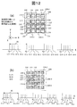
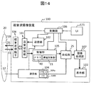
本発明の第一実施形態の超音波撮像装置の全体構成を示す図。1 is a diagram illustrating an overall configuration of an ultrasonic imaging apparatus according to a first embodiment of the present invention. 超音波探触子の超音波送受信面の概略構成を示す図。The figure which shows schematic structure of the ultrasonic transmission / reception surface of an ultrasonic probe. 第一実施形態の(a)送信開口の照射領域を示す説明図、(b)整相範囲と受信焦点を示す説明図、(c)合成後の受信焦点の範囲を示す説明図。(A) Explanatory drawing which shows irradiation area | region of transmission aperture of 1st embodiment, (b) Explanatory drawing which shows a phasing range and a receiving focus, (c) Explanatory drawing which shows the range of the receiving focal point after a synthesis | combination. 第一実施形態の超音波探触子の送信開口のグループと撮像すべき範囲の各領域との対応を示す説明図。Explanatory drawing which shows a response | compatibility with each area | region of the range which should be imaged, and the group of the transmission opening of the ultrasonic probe of 1st embodiment. 異なる心拍の同一時相t1のタイミングで送信開口から超音波を送信することを説明する図。The figure explaining transmitting an ultrasonic wave from a transmission opening at the timing of the same time phase t1 of a different heartbeat. 第一実施形態の撮像対象の動きを表す信号(心電信号)を説明する図。The figure explaining the signal (electrocardiogram signal) showing the motion of the imaging target of 1st embodiment. 第一実施形態の撮像対象の動きを表す信号(血流速度信号)を説明する図。The figure explaining the signal (blood-flow velocity signal) showing the motion of the imaging target of 1st embodiment. 第一実施形態の心拍周期に複数時相t1〜t4を設定した例を示す説明図。Explanatory drawing which shows the example which set multiple time phases t1-t4 to the heartbeat period of 1st embodiment. 撮像すべき範囲に設定した受信走査線を示す説明図。Explanatory drawing which shows the receiving scanning line set to the range which should be imaged. (a)〜(c)一次元に配列された送信開口に設定したグループのパターン(マップ)の例と、心拍周期に設定した時相との対応を示す図。(A)-(c) The figure which shows the response | compatibility with the example of the pattern (map) of the group set to the transmission opening arranged in one dimension, and the time phase set to the heartbeat period. (a)二次元に配列した送信開口と、撮像すべき範囲との関係を示す説明図、(b)撮像すべき範囲の各領域と、送信開口との関係を示す説明図。(A) Explanatory drawing which shows the relationship between the transmission aperture arranged in two dimensions, and the range which should be imaged, (b) Explanatory drawing which shows the relationship between each area | region of the range which should be imaged, and a transmission aperture. (a)、(b)二次元に配列された送信開口に設定したグループのパターン(マップ)の例と、心拍周期に設定した時相との対応を示す図。(A), (b) The figure which shows a response | compatibility with the example of the pattern (map) of the group set to the transmission opening arranged in two dimensions, and the time phase set to the heartbeat period. (a)、(b)二次元に配列された送信開口に設定したグループのパターン(マップ)の例と、心拍周期に設定した時相との対応を示す図。(A), (b) The figure which shows a response | compatibility with the example of the pattern (map) of the group set to the transmission opening arranged in two dimensions, and the time phase set to the heartbeat period. 第二実施形態の超音波撮像装置の全体構成を示す図。The figure which shows the whole structure of the ultrasonic imaging device of 2nd embodiment. 図14の超音波撮像装置の設定部と合成部の動作を示すフローチャート。15 is a flowchart showing operations of a setting unit and a combining unit of the ultrasonic imaging apparatus in FIG. 第二実施形態の送信開口とその整相範囲と整相範囲の合成との関係を示す説明図。Explanatory drawing which shows the relationship between the transmission opening of 2nd embodiment, its phasing range, and the synthesis | combination of a phasing range.

<<第一実施形態>>
第一実施形態の超音波撮像装置(超音波送受信装置)について図面を用いて説明する。図1は、第一実施形態の超音波撮像装置100の全体構成を示す図であり、図2は、超音波探触子108の超音波送受信面の概略構成(送信開口の配置例)を示す図である。図3は、第一実施形態の(a)送信開口の照射領域33を示す説明図、(b)整相範囲35と受信焦点を示す説明図、(c)合成後の受信焦点の範囲を示す説明図である。図4は、第一実施形態の超音波探触子108の送信開口のグループと撮像すべき範囲219の各領域との対応を示す説明図である。図5は、異なる心拍の同一時相t1のタイミングで送信開口110〜113等から超音波を送信することを説明する図である。
<< First Embodiment >>
An ultrasonic imaging apparatus (ultrasonic transmission / reception apparatus) according to a first embodiment will be described with reference to the drawings. FIG. 1 is a diagram illustrating an overall configuration of the ultrasonic imaging apparatus 100 according to the first embodiment, and FIG. 2 illustrates a schematic configuration of an ultrasonic transmission / reception surface of the ultrasonic probe 108 (an arrangement example of transmission openings). FIG. 3A is an explanatory diagram showing the irradiation area 33 of the transmission aperture in the first embodiment, FIG. 3B is an explanatory diagram showing the phasing range 35 and the reception focus, and FIG. 3C is a range of the reception focus after synthesis. It is explanatory drawing. FIG. 4 is an explanatory diagram showing a correspondence between a group of transmission apertures of the ultrasonic probe 108 of the first embodiment and each region of the range 219 to be imaged. FIG. 5 is a diagram for explaining that ultrasonic waves are transmitted from the transmission openings 110 to 113 at the same time phase t1 of different heartbeats.

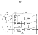
図1のように、超音波撮像装置100は、超音波探触子108と、送信部102と、受信部105と、設定部104と、合成部25とを有している。   As illustrated in FIG. 1, the ultrasonic imaging apparatus 100 includes an ultrasonic probe 108, a transmission unit 102, a reception unit 105, a setting unit 104, and a synthesis unit 25.

超音波探触子108は、図2のように、複数の所定の方向へ超音波を照射する超音波振動子の領域である送信開口110〜113等と、1以上の受信領域130を有する。複数の送信開口110〜113等および受信領域130は、それぞれ1以上の超音波振動子(トランスデューサ)によって構成される。超音波振動子は、電気信号を音波へ、音波を電気信号へと変換する機能を持つ。図2の例では、受信領域130は、一以上の超音波振動子の集合であるチャネル109によって構成され、送信開口110〜113等は、複数のチャネル109によって構成されている。また、超音波振動子は、複数(P個)のチャネル109〜109に仮想的もしくは物理的に分割されている。各チャネル109〜109は、1つもしくは複数の超音波振動子によって構成されている。 As shown in FIG. 2, the ultrasonic probe 108 has transmission openings 110 to 113 that are areas of ultrasonic transducers that irradiate ultrasonic waves in a plurality of predetermined directions, and one or more reception areas 130. The plurality of transmission openings 110 to 113 and the like and the reception area 130 are each configured by one or more ultrasonic transducers (transducers). The ultrasonic transducer has a function of converting an electric signal into a sound wave and a sound wave into an electric signal. In the example of FIG. 2, the reception region 130 is configured by a channel 109 that is a set of one or more ultrasonic transducers, and the transmission openings 110 to 113 and the like are configured by a plurality of channels 109. In addition, the ultrasonic transducer is virtually or physically divided into a plurality (P) of channels 109 1 to 109 P. Each of the channels 109 1 to 109 P is composed of one or a plurality of ultrasonic transducers.

なお、この構成に限らず、送信開口110〜113等がそれぞれ一つのチャネルによって構成されていてもよい。また、複数の送信開口110〜113等が、互いに重なりあっていてもよい。さらに、図2の超音波探触子は、一つのチャネル109が、送信および受信の両方を行う構成であるが、この構成に限らず、送信開口110〜113等と受信領域130のチャネルを分離してもよい。   Not limited to this configuration, each of the transmission apertures 110 to 113 may be configured by one channel. A plurality of transmission openings 110 to 113 may be overlapped with each other. In addition, the ultrasonic probe of FIG. 2 has a configuration in which one channel 109 performs both transmission and reception. However, the configuration is not limited to this, and the channels of the transmission apertures 110 to 113 and the reception area 130 are separated. May be.

送信部102は、送信開口110、111等ごとに、被検体の撮像対象20の撮像すべき範囲(撮像範囲)219に向かって超音波31を送信させる動作を行わせる。超音波31は、撮像対象20の所定の送信焦点に向かってフォーカス送信されてもよいし、図3(a)のように拡散送信されてもよい。これにより、送信開口ごとに、撮像すべき範囲219の照射領域33に超音波が照射される。   The transmission unit 102 performs an operation of transmitting the ultrasonic wave 31 toward the range (imaging range) 219 to be imaged of the imaging target 20 of the subject for each of the transmission apertures 110 and 111 and the like. The ultrasonic wave 31 may be focus-transmitted toward a predetermined transmission focus of the imaging target 20, or may be diffusely transmitted as shown in FIG. Thereby, an ultrasonic wave is irradiated to the irradiation area 33 of the range 219 to be imaged for each transmission aperture.

受信領域130は、撮像対象20からの超音波のエコーを受信し、電気的な受信信号を出力する。受信部105は、受信領域130の出力に対して整相処理を適用し、図3(b)のように照射領域33内に設定した整相範囲35の受信焦点(例えば52)についての受信信号(以下、焦点データ)を得る。合成部25は、図3(c)のように、同一の受信焦点52について、異なる送信開口(例えば、110、111)から異なる送信タイミングで送信された超音波のエコーから得た焦点データを、加算処理(送信間合成)する。例えば、送信開口110の位置に対応した整相範囲35−110と送信開口110の隣の送信開口111の位置に対応した整相範囲35−111とが重なる範囲135−nにおいて、画像を構築するための複数の点が集合した線である受信走査線241および画像を構築するための各点である受信焦点(以下、「撮像点」とも呼ぶ。)52が重なる。合成部25は135−nの範囲について,35−110と35−111それぞれの焦点データ同士を加算する。   The reception area 130 receives an ultrasonic echo from the imaging target 20 and outputs an electrical reception signal. The receiving unit 105 applies a phasing process to the output of the reception area 130, and receives a received signal for the reception focus (for example, 52) in the phasing range 35 set in the irradiation area 33 as shown in FIG. (Focus data) is obtained. As shown in FIG. 3C, the synthesizer 25 obtains focus data obtained from ultrasonic echoes transmitted at different transmission timings from different transmission apertures (for example, 110 and 111) with respect to the same reception focus 52. Addition processing (combination between transmissions) is performed. For example, an image is constructed in a range 135-n where a phasing range 35-110 corresponding to the position of the transmission opening 110 and a phasing range 35-111 corresponding to the position of the transmission opening 111 adjacent to the transmission opening 110 overlap. A reception scanning line 241 that is a line in which a plurality of points are collected and a reception focal point (hereinafter also referred to as “imaging point”) 52 that is each point for constructing an image overlap. The combining unit 25 adds the respective focus data of 35-110 and 35-111 for the range of 135-n.

このとき、設定部104は、撮像対象20の撮像範囲219を、図4のように複数の領域219−1〜219−4等に分割する。そして、設定部104は、同一の領域(例えば219−1)に対して、撮像対象20の動きに応じて撮像対象20における受信焦点52等の空間位置が所定の範囲内で一致するタイミング(例えば図5の時相t1)で、異なる複数の送信開口110〜113から、図5のように順に超音波を送信させる。なお、所定の範囲内で一致するタイミングには、完全に一致するタイミングのみならず、撮像対象の有する特徴的なゆらぎや,信号を検知する計測系の誤差等によって所定の範囲内でずれたタイミングも含まれる。   At this time, the setting unit 104 divides the imaging range 219 of the imaging target 20 into a plurality of areas 219-1 to 219-4 as shown in FIG. The setting unit 104 then sets the timing (for example, the spatial position of the reception focus 52 or the like on the imaging target 20 within a predetermined range in accordance with the movement of the imaging target 20 with respect to the same region (for example, 219-1) (for example, At time t1) in FIG. 5, ultrasonic waves are transmitted in order from a plurality of different transmission openings 110 to 113 as shown in FIG. Note that the timing that matches within the predetermined range is not only the timing that completely matches, but also the timing that deviates within the predetermined range due to characteristic fluctuations of the imaging target, errors in the measurement system that detects the signal, and the like. Is also included.

これにより、合成部25は、領域(例えば219−1)内の受信焦点52の空間位置が一致するタイミングで送信された超音波のエコーから得た焦点データを送信間で開口合成することができる。よって、撮像対象20に動きがあり、超音波の送信を繰り返している間に撮像対象20が動く場合であっても、撮像対象20の空間的位置が一致しているため、開口合成時に像ブレなどを起こすことなく、開口合成による高画質化の効果を得ることができる。   Thereby, the synthetic | combination part 25 can carry out aperture composition between the transmissions of the focus data obtained from the echo of the ultrasonic wave transmitted at the timing when the spatial position of the reception focus 52 in the region (for example, 219-1) matches. . Therefore, even when the imaging target 20 moves and the imaging target 20 moves while repeating the transmission of ultrasonic waves, the spatial position of the imaging target 20 matches, so image blurring occurs during aperture synthesis. The effect of high image quality by aperture synthesis can be obtained without causing any problems.

例えば、設定部104は、図1および図5のように、撮像対象20の周期的な動きに対応した信号12を受け取って、受け取った信号12に対して同一時相(例えばt1)となるタイミングで超音波の送信を行うよう指示する信号と、超音波の送信に用いる送信開口を指示する信号を送信部102に出力する。これにより、送信部102は、設定部140から指示された超音波探触子108の送信開口から、指示されたタイミングで、撮像範囲219の同一の領域219−1等に対して超音波を送信させる。   For example, as illustrated in FIGS. 1 and 5, the setting unit 104 receives the signal 12 corresponding to the periodic movement of the imaging target 20 and has the same time phase (for example, t1) with respect to the received signal 12. And outputs a signal instructing to transmit ultrasonic waves and a signal instructing a transmission aperture used for transmitting ultrasonic waves to the transmitting unit 102. As a result, the transmission unit 102 transmits ultrasonic waves from the transmission opening of the ultrasonic probe 108 instructed by the setting unit 140 to the same region 219-1 in the imaging range 219 at the instructed timing. Let

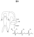
図6は、第一実施形態の撮像対象20の動きを表す信号(心電信号)を説明する図である。図7は、第一実施形態の撮像対象20の動きを表す信号(血流速度信号)を説明する図である。   FIG. 6 is a diagram illustrating a signal (electrocardiogram signal) representing the movement of the imaging target 20 according to the first embodiment. FIG. 7 is a diagram illustrating a signal (blood flow velocity signal) representing the movement of the imaging target 20 according to the first embodiment.

撮像対象20の周期的な動きに対応した信号12は、心電信号や、血流速度を示す信号や、呼吸動を示す信号を用いることができる。具体的には例えば、図6のように、心電計(心電図モニタ)60によって得られた撮像対象20の心電信号(心電波形)61を信号12として用いることが可能である。また、例えば、図7のように、超音波ドプラー血流計(血流速度モニタ)70によって撮像対象20の持つ血管73の血流速度を測定し、得られた血流速度信号62を信号12として用いることができる。   As the signal 12 corresponding to the periodic movement of the imaging target 20, an electrocardiogram signal, a signal indicating blood flow velocity, or a signal indicating respiratory motion can be used. Specifically, for example, as shown in FIG. 6, an electrocardiogram signal (electrocardiogram waveform) 61 of the imaging target 20 obtained by an electrocardiograph (electrocardiogram monitor) 60 can be used as the signal 12. Further, for example, as shown in FIG. 7, the blood flow velocity of the blood vessel 73 of the imaging target 20 is measured by an ultrasonic Doppler blood flow meter (blood flow velocity monitor) 70, and the obtained blood flow velocity signal 62 is obtained as a signal 12. Can be used as

同一時相のタイミングを判定する基準としては、信号周期を示す信号を検出して用いる。心電波形61の場合、例えばR波71を用いることができる。また、血流速度信号62の場合、拍動に同期した立上り時間72を用いることができる。   As a reference for determining the timing of the temporary phase, a signal indicating a signal period is detected and used. In the case of the electrocardiographic waveform 61, for example, an R wave 71 can be used. In the case of the blood flow velocity signal 62, the rise time 72 synchronized with the pulsation can be used.

なお,R波71や立上り時間72の時刻は,撮像対象の有する特徴的なゆらぎや,信号を検知する計測系の誤差等により完全に周期的な信号とならないことがある。このような場合においても,複数の信号12を用いた開口合成をおこなうことで,ゆらぎや誤差の範囲内で一致したタイミング(すなわち所定の範囲内で一致するタイミング)で送信させたことに等しくなる。   Note that the time of the R wave 71 and the rise time 72 may not be a completely periodic signal due to characteristic fluctuations of the imaging target, errors in the measurement system that detects the signal, and the like. Even in such a case, performing aperture synthesis using a plurality of signals 12 is equivalent to transmitting at a timing that matches within a range of fluctuation or error (that is, a timing that matches within a predetermined range). .

なお、図4のように、撮像範囲219内の同一の領域(例えば219−1)に対して超音波を送信する複数の送信開口110〜113は、送信順に互いに隣り合っていることが望ましい。これにより、超音波31の照射領域33の広い範囲を互いに重ね合わせることができるため、重なり合う照射領域33内の受信焦点52の焦点データを開口合成することができる。   As shown in FIG. 4, the plurality of transmission openings 110 to 113 that transmit ultrasonic waves to the same region (for example, 219-1) in the imaging range 219 are preferably adjacent to each other in the transmission order. Thereby, since the wide range of the irradiation region 33 of the ultrasonic wave 31 can be overlapped with each other, the focus data of the reception focus 52 in the overlapping irradiation region 33 can be aperture-synthesized.

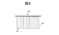
また、図8は、第一実施形態の心拍周期に複数時相t1〜t4を設定した例を示す説明図である。図9は、撮像範囲219に設定した受信走査線241を示す説明図である。図8のように、設定部104は、撮像対象20からの信号12の周期81−1〜81−4等に基づいて、同一の周期(例えば81−1)内に、複数の異なる時相t1、t2、t3、t4を設定することも可能である。この場合、異なる時相ごとに、異なる領域に対して異なる送信開口から順に超音波を送信させる。例えば、図4のように、時相t1では、撮像対象20の領域219−1に異なる4つの送信開口110〜113からそれぞれ超音波31を送信し、時相t2では、領域219−2に異なる4つの送信開口114〜117からそれぞれ超音波31を送信し、時相t3では領域219−3に4つの送信開口118〜121からそれぞれ超音波31を送信し、時相t4では領域219−4に送信開口122〜125からそれぞれ超音波31を送信する。このように、同一の周期内の異なる複数の時相から超音波を送信することにより、図9のように、撮像範囲219全体の受信走査線241についての受信焦点の焦点データ(すなわち画像)が得られるまでの時間を短縮することができる。   Moreover, FIG. 8 is explanatory drawing which shows the example which set multiple time phases t1-t4 to the heartbeat period of 1st embodiment. FIG. 9 is an explanatory diagram showing the reception scanning line 241 set in the imaging range 219. As shown in FIG. 8, the setting unit 104 has a plurality of different time phases t1 within the same period (for example, 81-1) based on the periods 81-1 to 81-4 of the signal 12 from the imaging target 20. , T2, t3, and t4 can be set. In this case, ultrasonic waves are transmitted in order from different transmission openings to different regions for different time phases. For example, as illustrated in FIG. 4, in the time phase t1, the ultrasonic waves 31 are transmitted from the four different transmission openings 110 to 113 to the region 219-1 of the imaging target 20, respectively, and in the time phase t2, the ultrasonic waves 31 are different to the region 219-2. The ultrasonic waves 31 are transmitted from the four transmission openings 114 to 117, respectively, and at the time phase t3, the ultrasonic waves 31 are transmitted from the four transmission openings 118 to 121 to the area 219-4, respectively, and to the area 219-4 at the time phase t4. The ultrasonic waves 31 are transmitted from the transmission openings 122 to 125, respectively. As described above, by transmitting ultrasonic waves from a plurality of different time phases within the same period, the focus data (that is, the image) of the reception focus for the reception scanning line 241 in the entire imaging range 219 is obtained as shown in FIG. Time until it can be obtained can be shortened.

同一の周期内の複数の時相から超音波を送信する場合、複数の領域219−1〜219−4のうち隣接する領域(例えば領域219−1と219−2)には、複数の異なる時相t1〜t4のうち連続する時相(例えばt1とt2)のタイミングで、超音波31が送信されることが望ましい。その理由は、隣接する領域の境界付近においても、開口合成による解像度の向上の効果が得られからである。隣接する領域219−1と219−2との境界付近の受信走査線241上の受信焦点52の焦点データを合成部25が合成する場合に、時相t1で送信された超音波31のエコーで得られた焦点データと、時相t2で送信された超音波31のエコーで得られた焦点データとを合成するため、撮像対象20の動きによって受信焦点52の位置は完全には一致しないが、連続する時相t1とt2であるため、撮像対象20の体動による位置ずれ量は最小である。よって、隣接する領域の境界付近における受信焦点52の位置ずれ量を最小限に抑制しながら開口合成することができ、隣接する領域219−1と領域219−2との境界付近における解像度の乱れを抑制しながら、開口合成による解像度の向上の効果を得ることができる。   When transmitting ultrasonic waves from a plurality of time phases within the same cycle, adjacent regions (for example, the regions 219-1 and 219-2) among the plurality of regions 219-1 to 219-4 have a plurality of different times. It is desirable that the ultrasonic wave 31 is transmitted at the timing of successive time phases (for example, t1 and t2) among the phases t1 to t4. This is because the effect of improving the resolution by aperture synthesis is obtained even in the vicinity of the boundary between adjacent regions. When the synthesizing unit 25 synthesizes the focus data of the reception focus 52 on the reception scanning line 241 near the boundary between the adjacent regions 219-1 and 219-2, the echo of the ultrasonic wave 31 transmitted at the time phase t1 is used. In order to synthesize the obtained focus data and the focus data obtained by the echo of the ultrasonic wave 31 transmitted at the time phase t2, the position of the reception focus 52 is not completely matched by the movement of the imaging target 20, Since the time phases t1 and t2 are continuous, the amount of displacement due to the body movement of the imaging target 20 is minimal. Therefore, aperture synthesis can be performed while minimizing the amount of positional deviation of the reception focal point 52 in the vicinity of the boundary between adjacent areas, and the disturbance in resolution near the boundary between the adjacent areas 219-1 and 219-2 can be reduced. While suppressing, the effect of improving the resolution by aperture synthesis can be obtained.

また、図10は、一次元に配列された送信開口に設定したグループのパターン(マップ)の例と、心拍周期に設定した時相との対応を示す図である。   FIG. 10 is a diagram showing a correspondence between an example of a group pattern (map) set in the transmission openings arranged in one dimension and a time phase set in the heartbeat cycle.

設定部104は、例えば図10(a)〜(c)のように、信号12の周期81の長さに応じて、同一周期81内に設定する時相の数を定めてもよい。これにより、例えば、撮像対象20の信号12の周期81に応じて、開口合成を行うことができる。   For example, as illustrated in FIGS. 10A to 10C, the setting unit 104 may determine the number of time phases to be set in the same period 81 according to the length of the period 81 of the signal 12. Thereby, for example, aperture synthesis can be performed according to the period 81 of the signal 12 of the imaging target 20.

また、設定部104は、同一の周期81内に設定した時相の数に応じて、撮像範囲219の領域219−1〜219−4のパターン(形状および配置)を設定する構成にしてもよい。具体的には、例えば、設定部104は、同一周期81内に設定する時相の数ごとに予め定めておいた、1以上の領域のパターン(領域パターン)を記憶するメモリ104aを有するように構成する。メモリ104aは、領域パターンを例えばマップとして記憶するがこれに限られない。設定部104は、同一の周期81内に設定した時相の数に基づいて、メモリ104aから対応する領域パターンを読み出して設定することができる。   The setting unit 104 may be configured to set the patterns (shape and arrangement) of the regions 219-1 to 219-4 of the imaging range 219 according to the number of time phases set within the same period 81. . Specifically, for example, the setting unit 104 includes a memory 104a that stores a pattern (region pattern) of one or more regions that are predetermined for each number of time phases set in the same period 81. Configure. The memory 104a stores the area pattern as a map, for example, but is not limited thereto. The setting unit 104 can read and set the corresponding area pattern from the memory 104a based on the number of time phases set within the same period 81.

例えば、設定部104は、複数の領域219−1〜219−4の形状に対応させて、超音波探触子108の複数の送信開口を、複数のグループに分割し、同一の領域(例えば219−1)には、その領域に対応するグループに含まれる複数の送信開口から同一時相で順に超音波31を送信させるように構成することが可能である。超音波探触子108の送信開口が一次元に配列された一次元アレイであり、信号12が心電信号61である場合の具体例を、図10(a)〜(c)に示す。一つの領域219−1〜219−4に送信する超音波31の数に対応する数の送信開口を含むグループ220−1〜220−6が、超音波探触子108に設定された複数のパターンが図10(a)〜(c)のように予め用意され、設定部104内のメモリ104aに格納されている。   For example, the setting unit 104 divides the plurality of transmission apertures of the ultrasound probe 108 into a plurality of groups corresponding to the shapes of the plurality of regions 219-1 to 219-4, and the same region (for example, 219). In (1), the ultrasonic waves 31 can be transmitted in order at the same time phase from a plurality of transmission apertures included in the group corresponding to the region. FIGS. 10A to 10C show specific examples when the transmission apertures of the ultrasonic probe 108 are a one-dimensional array in which the transmission apertures are arranged one-dimensionally and the signal 12 is an electrocardiogram signal 61. FIG. A plurality of patterns in which the groups 220-1 to 220-6 including the number of transmission apertures corresponding to the number of the ultrasonic waves 31 transmitted to one region 219-1 to 219-4 are set in the ultrasonic probe 108. Are prepared in advance as shown in FIGS. 10A to 10C and stored in the memory 104 a in the setting unit 104.

図10(a)のパターンは、心電信号12の周期81が長く、同一周期81内に6つの時相t1〜t6が設定可能な場合のパターンである。送信開口110〜125を備える超音波探触子108に6つのグループ220−1〜220−6が設定され、各グループはそれぞれ3つの送信開口を含み、3心拍の期間で超音波探触子108の全ての送信開口110〜125から送信を完了し、グループ220−1〜220−6に対応する撮像対象20の領域219−1〜219−6の受信走査線241についての焦点データを取得する。   The pattern of FIG. 10A is a pattern when the period 81 of the electrocardiogram signal 12 is long and six time phases t1 to t6 can be set in the same period 81. Six groups 220-1 to 220-6 are set in the ultrasound probe 108 having the transmission apertures 110 to 125, and each group includes three transmission apertures, and the ultrasound probe 108 in a period of 3 heartbeats. The transmission is completed from all the transmission apertures 110 to 125, and the focus data for the reception scanning lines 241 in the areas 219-1 to 219-6 of the imaging target 20 corresponding to the groups 220-1 to 220-6 is acquired.

なお、グループ220−6には、1つの送信開口125が含まれているが、これは、超音波探触子108に各グループを設定した結果、余った送信開口125が1つのグループを構成していることを示す。この場合、時相t6−2と時相t6−3には、超音波31を送信する送信開口が存在しないため、超音波31の送信は行われない。   The group 220-6 includes one transmission aperture 125. As a result of setting each group in the ultrasonic probe 108, the remaining transmission apertures 125 constitute one group. Indicates that In this case, since the transmission opening for transmitting the ultrasonic wave 31 does not exist in the time phase t6-2 and the time phase t6-3, the ultrasonic wave 31 is not transmitted.

図10(b)のパターンは、心電信号12の周期が図10(a)よりも短く、同一周期81内に4つの時相t1〜t4が設定可能な場合のパターンである。超音波探触子108に4つのグループ220−1〜220−4が設定され、各グループは、4つの送信開口を含み、4心拍の期間で超音波探触子108の全ての送信開口110〜125から送信を完了し、グループ220−1〜220−4に対応する領域219−1〜219−4の全ての受信走査線241についての焦点データを取得する。   The pattern of FIG. 10B is a pattern when the period of the electrocardiogram signal 12 is shorter than that of FIG. 10A and four time phases t1 to t4 can be set within the same period 81. Four groups 220-1 to 220-4 are set in the ultrasound probe 108, and each group includes four transmission apertures. All the transmission apertures 110 to 110 of the ultrasound probe 108 in a period of four heartbeats. The transmission is completed from 125, and the focus data for all the reception scanning lines 241 in the areas 219-1 to 219-4 corresponding to the groups 220-1 to 220-4 is acquired.

一方、図10(c)のパターンは、心電信号12の周期が図10(b)よりもさらに短く、同一周期81内に3つの時相t1〜t3が設定可能な場合のパターンである。超音波探触子108に3つのグループ220−1〜220−3が設定され、各グループは、6つの送信開口を含み、3心拍の期間で超音波探触子108の全ての送信開口110〜125から送信を完了し、グループ220−1〜220−3に対応する領域219−1〜219−3の全ての受信走査線241についての焦点データを取得する。   On the other hand, the pattern of FIG. 10C is a pattern when the period of the electrocardiogram signal 12 is further shorter than that of FIG. 10B and three time phases t1 to t3 can be set in the same period 81. Three groups 220-1 to 220-3 are set in the ultrasound probe 108, each group including six transmission apertures, and all the transmission apertures 110 to 110 of the ultrasound probe 108 in a period of three heartbeats. The transmission is completed from 125, and the focus data for all the reception scanning lines 241 in the areas 219-1 to 219-3 corresponding to the groups 220-1 to 220-3 is acquired.

なお、図10(a)と同様に、グループ220−3には、4つの送信開口122〜125が含まれる。   As in FIG. 10A, the group 220-3 includes four transmission openings 122 to 125.

なお、図10(b)のように、各周期内で送信する回数が一定である方が、送信を行えない待ち時間が発生しないため、撮像効率を上げられる。このように、設定部104は待ち時間が発生しないようなパターン図10(b)を自動的に選択してもよい。   Note that as shown in FIG. 10B, when the number of times of transmission is constant within each period, a waiting time during which transmission cannot be performed does not occur, so that imaging efficiency can be increased. As described above, the setting unit 104 may automatically select a pattern diagram 10 (b) that does not generate a waiting time.

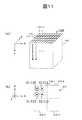
また、図11は、(a)二次元に配列した送信開口と、撮像範囲219との関係を示す説明図、(b)撮像範囲219の各領域と、送信開口との関係を示す説明図である。図12と図13は、二次元に配列された送信開口に設定したグループのパターン(マップ)の例と、心拍周期に設定した時相との対応を示す図である。   FIGS. 11A and 11B are (a) an explanatory diagram showing a relationship between two-dimensionally arranged transmission apertures and the imaging range 219, and (b) an explanatory diagram showing a relationship between each region of the imaging range 219 and the transmission apertures. is there. FIG. 12 and FIG. 13 are diagrams showing a correspondence between an example of a group pattern (map) set for two-dimensionally arranged transmission apertures and a time phase set for a heartbeat cycle.

図11(a)は、送信開口はx−y軸方向に二次元配置され、送信開口から三次元空間設定される撮像範囲219に向かって超音波が送信される関係を示す。図11(b)は、図11(a)のx−y軸断面を示し、4つに設定された撮像範囲219の、219−1に送信開口110〜113によって照射された超音波31−110等の位置関係を示す。   FIG. 11A shows a relationship in which the transmission aperture is two-dimensionally arranged in the xy axis direction, and ultrasonic waves are transmitted from the transmission aperture toward the imaging range 219 set in a three-dimensional space. FIG. 11B shows an xy-axis cross section of FIG. 11A, and the ultrasonic waves 31-110 irradiated to the transmission apertures 110 to 113 in the image pickup range 219 set to four are set to 219-1. The positional relationship of etc. is shown.

超音波探触子108の送信開口が、図11のように二次元に配列された二次元アレイである場合に、超音波探触子108に設定するグループ220−1等のパターンの例を図12(a)、(b)および図13(a)、(b)に示す。図12(a)のパターンは、同一周期81内に4つの時相t1〜t4が設定可能な場合のパターンである。16個の送信開口110〜125を備える超音波探触子108に4つのグループ220−1〜220−4が設定され、各グループはそれぞれ4つの送信開口を含み、4心拍の期間で超音波探触子108の全ての送信開口110〜125から超音波31の送信を完了し、図11(b)のようにグループ220−1〜220−4に対応する領域219−1〜219−4の焦点データを取得する。   When the transmission aperture of the ultrasonic probe 108 is a two-dimensional array arranged two-dimensionally as shown in FIG. 11, an example of a pattern such as a group 220-1 set in the ultrasonic probe 108 is illustrated. 12 (a) and 12 (b) and FIGS. 13 (a) and 13 (b). The pattern of FIG. 12A is a pattern when four time phases t1 to t4 can be set in the same period 81. Four groups 220-1 to 220-4 are set in the ultrasonic probe 108 having 16 transmission apertures 110 to 125, and each group includes four transmission apertures, and the ultrasonic probe is in a period of 4 heartbeats. The transmission of the ultrasonic wave 31 is completed from all the transmission openings 110 to 125 of the touch element 108, and the focal points of the regions 219-1 to 219-4 corresponding to the groups 220-1 to 220-4 as shown in FIG. Get the data.

図12(b)のパターンは、同一周期81内に5つの時相t1〜t5が設定可能な場合のパターンである。25個の送信開口110等を備える超音波探触子108に5つのグループ220−1〜220−5が設定され、各グループはそれぞれ5つの送信開口を含み、5心拍の期間で超音波探触子108の25個全ての送信開口110等から超音波31の送信を完了し、グループ220−1〜220−5に対応する領域219−1〜219−5の焦点データを取得する。   The pattern of FIG. 12B is a pattern when five time phases t1 to t5 can be set in the same period 81. Five groups 220-1 to 220-5 are set in the ultrasonic probe 108 having 25 transmission apertures 110 and the like, and each group includes five transmission apertures, and the ultrasonic probe is performed in a period of 5 heartbeats. The transmission of the ultrasonic waves 31 is completed from all 25 transmission apertures 110 and the like of the child 108, and the focus data of the areas 219-1 to 219-5 corresponding to the groups 220-1 to 220-5 are acquired.

図13(a)のパターンは、同一周期81内に6つの時相t1〜t6が設定可能な場合のパターンである。24個の送信開口110等を備える超音波探触子108に6つのグループ220−1〜220−6が設定され、各グループはそれぞれ4つの送信開口を含み、4心拍の期間で超音波探触子108の24個全ての送信開口110等から超音波31の送信を完了し、グループ220−1〜220−6に対応する領域219−1〜219−6の焦点データを取得する。   The pattern of FIG. 13A is a pattern when six time phases t1 to t6 can be set in the same period 81. Six groups 220-1 to 220-6 are set in the ultrasonic probe 108 having 24 transmission apertures 110 and the like, and each group includes four transmission apertures, and the ultrasonic probe in a period of 4 heartbeats. The transmission of the ultrasonic wave 31 is completed from all 24 transmission apertures 110 and the like of the child 108, and the focus data of the areas 219-1 to 219-6 corresponding to the groups 220-1 to 220-6 are acquired.

図13(b)のパターンは、同一周期81内に8つの時相t1〜t8が設定可能な場合のパターンである。24個の送信開口110等を備える超音波探触子108に8つのグループ220−1〜220−8が設定され、各グループはそれぞれ3つの送信開口を含み、3心拍の期間で超音波探触子108の24個全ての送信開口110等から超音波31の送信を完了し、グループ220−1〜220−8に対応する領域219−1〜219−8の焦点データを取得する。   The pattern of FIG. 13B is a pattern when eight time phases t1 to t8 can be set in the same period 81. Eight groups 220-1 to 220-8 are set in the ultrasonic probe 108 having 24 transmission apertures 110 and the like, and each group includes three transmission apertures, and the ultrasonic probe is performed in a period of 3 heartbeats. The transmission of the ultrasonic wave 31 is completed from all 24 transmission apertures 110 and the like of the child 108, and the focus data of the regions 219-1 to 219-8 corresponding to the groups 220-1 to 220-8 are acquired.

設定部104は、撮像対象20の動きに対応する信号12の周期を検出し、周期の長さに応じて、1周期内に設定する時相数を設定し、時相数に応じて、図10または図12〜図13のパターンの中から送信開口のグループのパターンを選択することができる。   The setting unit 104 detects the period of the signal 12 corresponding to the movement of the imaging target 20, sets the number of time phases set within one period according to the length of the period, and sets the number of time phases according to the number of time phases. The pattern of the group of transmission apertures can be selected from the patterns of 10 or FIGS.

設定部104は、グループ220−1内の複数の送信開口110、111、112等のうち、隣り合う送信開口の順に超音波を送信させることが望ましい。隣り合う送信開口の順に超音波を送信させることにより、超音波の照射領域を大きく重ねることが可能になり、送信のたびに重なり合う広い範囲で開口合成をすることが可能になるためである。   The setting unit 104 preferably transmits ultrasonic waves in the order of adjacent transmission apertures among the plurality of transmission apertures 110, 111, 112, and the like in the group 220-1. This is because by transmitting ultrasonic waves in the order of adjacent transmission apertures, it is possible to largely overlap ultrasonic irradiation regions, and it is possible to synthesize apertures in a wide range that overlaps each time transmission is performed.

このように、第1の実施形態の超音波撮像装置を用いることにより、撮像対象に動きがある場合であっても、動きの影響を抑制して、開口合成による解像度の高い画像を得ることができる。例えば、生体の撮像において、自発的に動く臓器である心臓が撮像対象である場合はもちろん、その他の部位、頸動脈や肝臓のように心臓の拍動の影響を受けて動く部位を撮像対象とする場合にも、開口合成により解像度の高い画像を得ることができる。   As described above, by using the ultrasonic imaging apparatus according to the first embodiment, even when there is a motion in the imaging target, it is possible to suppress the influence of the motion and obtain an image with high resolution by aperture synthesis. it can. For example, in living body imaging, not only the heart, which is a spontaneously moving organ, is the imaging target, but also other parts, such as the carotid artery and liver, which are affected by the heartbeat, are considered as imaging targets. In this case, a high resolution image can be obtained by aperture synthesis.

<<第二実施形態>>
第二実施形態の超音波撮像装置の具体的な構成例について説明する。
<< Second Embodiment >>
A specific configuration example of the ultrasonic imaging apparatus according to the second embodiment will be described.

<装置の全体構成>
図14は、第二実施形態の超音波撮像装置100の全体構成を示す図である。図14において、第一実施形態の図1の構成と同様の構成は、同じ符号を付している。超音波撮像装置100は、第1の実施形態と同様に、超音波探触子108と送信部102と受信部105と合成部25と設定部104とを備え、これらに加えて、第二実施形態では、制御部106と、ユーザインタフェース(UI)121と、送受切替部101と、画像処理部107と、表示部122と、を備えている。
<Overall configuration of device>
FIG. 14 is a diagram illustrating an overall configuration of the ultrasonic imaging apparatus 100 according to the second embodiment. In FIG. 14, the same components as those of the first embodiment shown in FIG. Similar to the first embodiment, the ultrasonic imaging apparatus 100 includes an ultrasonic probe 108, a transmission unit 102, a reception unit 105, a synthesis unit 25, and a setting unit 104. The embodiment includes a control unit 106, a user interface (UI) 121, a transmission / reception switching unit 101, an image processing unit 107, and a display unit 122.

制御部106は、超音波撮像装置100全体の動作を制御する。UI121は、超音波撮像装置100を使用するユーザからの指示、各種パラメータの入力等を受け付けるインタフェースである。送受切替部101は、超音波探触子108を超音波送信時には送信部102と接続し、超音波受信時には受信部105と接続するように、超音波探触子108の接続先を選択する切り替えを制御部106の制御下で行う。画像処理部107は、合成部25が開口合成した後の焦点データを用いて、超音波画像を生成する。表示部122は、超音波画像を表示する。   The control unit 106 controls the overall operation of the ultrasonic imaging apparatus 100. The UI 121 is an interface that accepts an instruction from a user who uses the ultrasonic imaging apparatus 100, input of various parameters, and the like. The transmission / reception switching unit 101 is a switch for selecting the connection destination of the ultrasonic probe 108 so that the ultrasonic probe 108 is connected to the transmission unit 102 at the time of ultrasonic transmission and to the reception unit 105 at the time of ultrasonic reception. Is performed under the control of the control unit 106. The image processing unit 107 generates an ultrasonic image using the focus data after the synthesis unit 25 performs aperture synthesis. The display unit 122 displays an ultrasonic image.

超音波探触子108は、所定の配列で一次元または二次元に配列された超音波振動子(トランスデューサ)を複数個備える。超音波探触子108は、超音波振動子が配置された面(超音波送受面)を撮像対象20に接触させて使用するのに適した外形に仕立てられている。   The ultrasonic probe 108 includes a plurality of ultrasonic transducers (transducers) arranged one-dimensionally or two-dimensionally in a predetermined arrangement. The ultrasonic probe 108 is tailored to have an outer shape suitable for use by bringing the surface on which the ultrasonic transducer is disposed (ultrasonic transmission / reception surface) into contact with the imaging target 20.

送信開口110等は、一つのチャネル109等と同じ大きさであってもよいし、図2のように複数のチャネルによって一つの送信開口を構成してもよい。以下の説明では、一つの送信開口110として、隣り合う複数(図2では4個)のチャネルを用いる例について説明する。なお複数の送信開口(110、111、112、113)は、一部が重なるように設定してもよい。 Etc. transmit aperture 110 can be the same size as the one channel 109 1, such as may constitute a single transmit aperture by a plurality of channels as shown in FIG. In the following description, an example in which a plurality of adjacent channels (four in FIG. 2) are used as one transmission aperture 110 will be described. The plurality of transmission apertures (110, 111, 112, 113) may be set so as to partially overlap.

また、以下の説明ではチャネル109〜109の一つ一つを受信領域109として用いる。なお、2以上のチャネルを一つの受信領域109として用いることももちろん可能である。 In the following description, each of the channels 109 1 to 109 P is used as the reception area 109. Of course, it is possible to use two or more channels as one reception area 109.

<撮像範囲219>
超音波撮像装置100は、UI121からの指定もしくはUI121からの入力パラメータに基づいて自動的に撮像対象20の撮像範囲219を決定する。
<Imaging range 219>
The ultrasonic imaging apparatus 100 automatically determines the imaging range 219 of the imaging target 20 based on designation from the UI 121 or input parameters from the UI 121.

<送信部102>
送信部102は、設定部104からの指示に従って、超音波探触子108の予め定めた送信開口(例えば110)を選択し、選択した送信開口110に超音波31を送信させる送信信号を生成する。具体的には、波形種類、遅延時間、振幅変調、重み付け等を決定し、それに応じた送信信号を生成する。送信部102は、生成した送信信号を、送信開口110を構成するチャネルの超音波振動子のそれぞれに受け渡し、送信開口110から、照射領域33に超音波31を例えば図3(a)のように送信させる。送信部102は、この動作を、後述する設定部104が設定したタイミングで、送信開口110〜113等にそれぞれ実行させる。
<Transmitter 102>
The transmission unit 102 selects a predetermined transmission opening (for example, 110) of the ultrasonic probe 108 in accordance with an instruction from the setting unit 104, and generates a transmission signal for transmitting the ultrasonic wave 31 to the selected transmission opening 110. . Specifically, the waveform type, delay time, amplitude modulation, weighting, and the like are determined, and a transmission signal corresponding to the waveform type is generated. The transmission unit 102 delivers the generated transmission signal to each of the ultrasonic transducers of the channels constituting the transmission opening 110, and the ultrasonic wave 31 is transmitted from the transmission opening 110 to the irradiation region 33 as shown in FIG. 3A, for example. Send it. The transmission unit 102 causes the transmission openings 110 to 113 to execute this operation at the timing set by the setting unit 104 described later.

<受信部105>
送信開口110〜113等のいずれかから撮像範囲219に超音波31が送信されると、撮像範囲219ではエコーが生じる。超音波探触子108の受信開口(チャネル)109は、エコーを受信し、電気信号に変換する。受信部105は、図14に示すように、メモリ40と、遅延加算部21とを備えている。送信のたび得られた受信信号は、メモリ40に一旦格納される。遅延加算部21は、メモリ40から受信信号を読み出し、チャネルごとに所定の遅延値だけ遅延させた後、合算処理することにより、所定の撮像点52に焦点を結んだ焦点データを生成する(受信ビームフォーミング)。受信部105は、生成した焦点データを合成部25に受け渡す。受信ビームフォーミングには、超音波探触子108のすべてのチャネル109〜109の受信信号を用いてもよいし、所定の受信開口(アクティブチャネル)内のチャネルの受信信号のみを用いてもよい。
<Receiving unit 105>
When the ultrasonic wave 31 is transmitted to the imaging range 219 from any one of the transmission openings 110 to 113, an echo is generated in the imaging range 219. The reception aperture (channel) 109 of the ultrasonic probe 108 receives the echo and converts it into an electrical signal. As illustrated in FIG. 14, the reception unit 105 includes a memory 40 and a delay addition unit 21. The received signal obtained each time transmission is temporarily stored in the memory 40. The delay adder 21 reads out the received signal from the memory 40, delays it by a predetermined delay value for each channel, and then performs addition processing to generate focus data focused on a predetermined imaging point 52 (reception). Beam forming). The receiving unit 105 passes the generated focus data to the synthesizing unit 25. For reception beam forming, reception signals of all the channels 109 1 to 109 P of the ultrasonic probe 108 may be used, or only reception signals of channels within a predetermined reception aperture (active channel) may be used. Good.

なお、制御部106は、図9のように撮像範囲219の予め定めた位置に複数の受信走査線241を設定する。また、制御部106は、受信部105に対して、送信時の送信開口110の位置に対応した所定の整相範囲35−110を図3(b)のように設定し、この整相範囲35に含まれる複数の受信走査線241上のすべての受信焦点52について、焦点データを生成させる。これにより、少なくとも隣接する送信開口111に対応した整相範囲35−111と、送信開口110に対応した整相範囲35−110と、が重なる範囲135−nにおいては、受信走査線241および撮像点52が重なるため、合成部25が焦点データを加算することができる。   Note that the control unit 106 sets a plurality of reception scanning lines 241 at predetermined positions in the imaging range 219 as shown in FIG. Further, the control unit 106 sets a predetermined phasing range 35-110 corresponding to the position of the transmission opening 110 at the time of transmission to the receiving unit 105 as shown in FIG. Focus data is generated for all the reception focal points 52 on the plurality of reception scanning lines 241 included in. Thus, at least in the range 135-n where the phasing range 35-111 corresponding to the adjacent transmission aperture 111 and the phasing range 35-110 corresponding to the transmission aperture 110 overlap, the reception scanning line 241 and the imaging point Since 52 overlaps, the synthesizing unit 25 can add the focus data.

<合成部25>
合成部25は、図3(c)のように、受け渡された同じ座標の複数の焦点データを加算することにより合成する。このとき、設定部104から設定された範囲に応じて合成する焦点データを選択する。図9のように、撮像範囲219のすべての領域の受信走査線241の合成後の焦点データがそろった後、合成後のデータは画像処理部107に受け渡され、画像処理部107は、表示用の画像データとして受け取ったデータを加工処理し、表示部122に受け渡し、表示部122に表示させる。
<Synthesis unit 25>
As shown in FIG. 3C, the synthesizer 25 synthesizes by adding a plurality of pieces of focus data having the same coordinates transferred. At this time, the focus data to be combined is selected according to the range set by the setting unit 104. As shown in FIG. 9, after the combined focus data of the reception scanning lines 241 in all the areas of the imaging range 219 are collected, the combined data is transferred to the image processing unit 107, and the image processing unit 107 Data received as image data for processing is processed, transferred to the display unit 122, and displayed on the display unit 122.

<設定部104>
設定部104は、撮像対象20の撮像範囲219を複数の領域に分割し、同一の領域に対して撮像対象20の動きに応じて撮像対象における受信焦点の空間位置が一致するタイミングで、複数の送信開口から順に超音波31を送信させる動作をする。これをソフトウエアで実現するために、設定部104は、メモリ104aとCPU(Central Processing Unit)104bとを有し、CPU104bがメモリ104aに予め格納されたプログラムを読み込んで実行することにより、図15のように動作する。なお、設定部104の動作の一部または全部を、ASIC(Application Specific Integrated Circuit)やFPGA(Field−Programmable Gate Array)等のハードウエアにより実現することももちろん可能である。
<Setting unit 104>
The setting unit 104 divides the imaging range 219 of the imaging target 20 into a plurality of areas, and at a timing when the spatial position of the reception focus in the imaging target matches the same area according to the movement of the imaging target 20. The operation of transmitting the ultrasonic waves 31 in order from the transmission opening is performed. In order to realize this by software, the setting unit 104 includes a memory 104a and a CPU (Central Processing Unit) 104b. The CPU 104b reads and executes a program stored in advance in the memory 104a, so that FIG. Behaves like Of course, part or all of the operation of the setting unit 104 may be realized by hardware such as ASIC (Application Specific Integrated Circuit) or FPGA (Field-Programmable Gate Array).

図15および図16を用いて、設定部104と合成部25の動作を説明する。図15は、図14の超音波撮像装置の設定部と合成部の動作を示すフローチャートであり、図16は、第二実施形態の送信開口とその整相範囲と整相範囲の合成との関係を示す説明図である。ここでは、一例として、撮像対象20の心電信号61を信号12として用いる。メモリ104a内には、送信開口のグループ220のパターン(配置パターン)を定めるマップ(例えば、図10(a)〜(c)ならびに図12(a)、(b)および図13(a)、(b)のようなマップ)が、ユーザが入力可能な、1心拍周期81中の送信回数(時相数N)および1枚の画像の生成に用いる総心拍数Mの組み合わせごとに、予め格納されている。   The operations of the setting unit 104 and the combining unit 25 will be described with reference to FIGS. 15 and 16. FIG. 15 is a flowchart showing the operations of the setting unit and the synthesizing unit of the ultrasonic imaging apparatus of FIG. 14, and FIG. 16 shows the relationship between the transmission aperture, its phasing range, and the phasing range synthesis of the second embodiment. It is explanatory drawing which shows. Here, as an example, the electrocardiogram signal 61 of the imaging target 20 is used as the signal 12. In the memory 104a, maps (for example, FIGS. 10 (a) to 10 (c) and FIGS. 12 (a), 12 (b) and 13 (a), (a), which define a pattern (arrangement pattern) of the transmission aperture group 220, b) is stored in advance for each combination of the number of transmissions (number of time phases N) during one heartbeat period 81 and the total heart rate M used for generating one image, which can be input by the user. ing.

まず、設定部104は、ユーザから撮像条件の入力を受け付けるための予め定めた入力画面を表示部122に表示させ、この入力画面上で、撮像パラメータを受け付ける(ステップ140)。具体的には、設定部104は、撮像範囲219、撮像深度D、1画像を構築するために用いる送信開口数S、画像更新(1枚の画像生成)までに用いる総心拍数M、ならびに、撮像に用いる超音波探触子108が一次元アレイか二次元アレイかの選択の入力を撮像パラメータとして受け付ける(ステップ140)。なお、撮像範囲219、撮像深度Dおよび送信開口数Sは、予め定めておいた値を用いてもよく、他の撮像条件に基づいて予め定めた演算方法によって設定部104が算出してもよい。また、超音波探触子108が、一次元アレイか二次元アレイかは、制御部106が超音波探触子108の種類の判別機能を有する場合には、制御部106から判別結果を設定部104が受け取ることにより把握してもよい。   First, the setting unit 104 causes the display unit 122 to display a predetermined input screen for accepting input of imaging conditions from the user, and accepts imaging parameters on the input screen (step 140). Specifically, the setting unit 104 includes an imaging range 219, an imaging depth D, a transmission numerical aperture S used to construct an image, a total heart rate M used until image update (one image generation), and An input for selecting whether the ultrasonic probe 108 used for imaging is a one-dimensional array or a two-dimensional array is received as an imaging parameter (step 140). The imaging range 219, the imaging depth D, and the transmission numerical aperture S may use predetermined values, or may be calculated by the setting unit 104 by a predetermined calculation method based on other imaging conditions. . Whether the ultrasonic probe 108 is a one-dimensional array or a two-dimensional array, when the control unit 106 has a function of discriminating the type of the ultrasonic probe 108, a determination result is set from the control unit 106. You may grasp | ascertain by 104 receiving.

設定部104は、撮像対象20の心電計60から心電信号12を受け取り、1心拍の周期Tを算出する(ステップ141)。設定部104は、算出した心拍の周期Tを予め定めておいた超音波を送信可能な最小時間間隔で除し、1心拍周期Tから1心拍中に送信可能な送信回数(時相数)である最大送信回数Nmaxを算出する(ステップ142)。具体的には例えば、ステップ140で受け付けた撮像深度がD[mm]、媒質の音速がC[mm/s]、予め定められた送受信号の受け渡し等の処理に要する時間がα[s]の場合、最大送信回数Nmax=T/(2*D/C+α)となる。   The setting unit 104 receives the electrocardiogram signal 12 from the electrocardiograph 60 of the imaging target 20 and calculates a cycle T of one heartbeat (step 141). The setting unit 104 divides the calculated heartbeat period T by a predetermined minimum time interval at which ultrasound can be transmitted, and the number of transmissions (number of time phases) that can be transmitted during one heartbeat from one heartbeat period T. A certain maximum number of transmissions Nmax is calculated (step 142). Specifically, for example, the imaging depth received in step 140 is D [mm], the sound speed of the medium is C [mm / s], and the time required for processing such as delivery of a predetermined transmission / reception signal is α [s]. In this case, the maximum number of transmissions Nmax = T / (2 * D / C + α).

次に、設定部104は、ステップ140で受け付けた、1画像を構築するために用いる送信開口数Sと、画像更新(1枚の画像生成)までに用いる総心拍数Mを受け取り、1心拍中に送信する送信回数Nを、N=S/M(ただし、N≦Nmaxとする)により算出する。設定部104は、算出した送信回数Nと、Nmaxとを表示部122に表示する。ユーザは、表示されたNmaxの値を確認し、N≦Nmaxの制約下で、高画質を重視するなら1画像を構築するために用いる送信開口の数Sを大きくし、リアルタイム性を重視するならMを下げるなどの調整を行い、設定部104はこの調整を受け付ける。これにより、設定部104は、1心拍中に送信する送信回数Nと、画像更新(1枚の画像生成、画像化)までに用いる総心拍数Mを設定する(ステップ143)。   Next, the setting unit 104 receives the transmission numerical aperture S used for constructing one image received in step 140 and the total heart rate M used until image update (one image generation). The number N of times of transmission to be transmitted is calculated by N = S / M (where N ≦ Nmax). The setting unit 104 displays the calculated number of transmissions N and Nmax on the display unit 122. The user confirms the displayed value of Nmax, and under the constraint of N ≦ Nmax, if importance is attached to high image quality, the number S of transmission apertures used for constructing one image is increased, and real-time characteristics are emphasized. Adjustment such as lowering M is performed, and the setting unit 104 accepts this adjustment. Thereby, the setting unit 104 sets the number N of transmissions transmitted during one heartbeat and the total heart rate M used until image update (one image generation, imaging) (step 143).

つぎに、設定部104は、送信回数(時相数)N、総心拍数M、ならびに、超音波探触子108が一次元アレイか二次元アレイか、に応じて、送信開口110等のグループ220−1等の配置パターン(マップ)を、メモリ104a内に格納されているマップの中から選択する(ステップ144)。   Next, the setting unit 104 selects a group such as the transmission aperture 110 according to the number of transmissions (number of time phases) N, the total heart rate M, and whether the ultrasonic probe 108 is a one-dimensional array or a two-dimensional array. An arrangement pattern (map) such as 220-1 is selected from the maps stored in the memory 104a (step 144).

UI121を介してスキャン開始の指示を設定部104が受けたならば、設定部104は、i枚目(撮像画像番号i)の画像を生成するため、心電信号12の例えばR波を検出し、その時刻をt0とし、心拍数m、送信回数nをカウントし、時刻t0を基準として予め定めた時相tn-mのタイミングで、選択したマップにおいて時刻tn-mで超音波31を送信するよう定められている送信開口から超音波31を送信するように送信部102に指示する信号を出力する(ステップ145〜148)。具体的には例えば、図12(a)に示す、N=4、M=4のマップがステップ144で選択されている場合、設定部104は、1枚目の画像を生成するために、撮像画像番号i=1を設定し(ステップ145)、心電信号12の例えばR波を検出し、その時刻t0とし、スキャンを開始して心拍数m=1をカウントする(ステップ146)。設定部104は、送信回数n=1をカウントし(ステップ147)、ステップ144で選択されたマップの時相tn-m=t1-1において、時刻t1-1で超音波31送信するよう設定された送信開口110(グループ220−1)から超音波31を送信するよう送信部102に指示する(ステップ148)。これにより、送信部102は、超音波探触子108の送信開口110aから超音波31を送信させる。被検体からのエコーは、超音波探触子108の複数の受信領域109〜109により受信される。受信部105は、図3(b)、図16のように、送信開口110を中心に所定の整相範囲35−110を設定し、整相範囲35−110内の受信走査線上の受信焦点の焦点データを生成し、内蔵するメモリ40に心拍数m=1と対応させて格納する。メモリ40内には、送信開口ごとに、その送信開口からの送信で得られた焦点データを格納する領域が用意されている。 When the setting unit 104 receives a scan start instruction via the UI 121, the setting unit 104 detects, for example, an R wave of the electrocardiogram signal 12 in order to generate an i-th image (captured image number i). The time is t0, the heart rate m and the number of transmissions n are counted, and the ultrasonic wave 31 is transmitted at the time tn-m in the selected map at the timing of the time phase tn-m determined in advance with respect to the time t0. A signal instructing the transmitting unit 102 to transmit the ultrasonic wave 31 from the transmission aperture determined to be output is output (steps 145 to 148). Specifically, for example, when the map of N = 4 and M = 4 shown in FIG. 12A is selected in step 144, the setting unit 104 takes an image to generate the first image. An image number i = 1 is set (step 145), for example, an R wave of the electrocardiogram signal 12 is detected, and at time t0, scanning is started and a heart rate m = 1 is counted (step 146). The setting unit 104 counts the number of transmissions n = 1 (step 147), and is set to transmit the ultrasonic wave 31 at time t1-1 in the time phase tn-m = t1-1 of the map selected in step 144. The transmission unit 102 is instructed to transmit the ultrasonic wave 31 from the transmission aperture 110 (group 220-1) (step 148). Thereby, the transmission unit 102 transmits the ultrasonic waves 31 from the transmission opening 110a of the ultrasonic probe 108. Echoes from the subject are received by the plurality of receiving areas 109 1 to 109 P of the ultrasonic probe 108. As shown in FIGS. 3B and 16, the receiving unit 105 sets a predetermined phasing range 35-110 around the transmission aperture 110, and sets the reception focus on the reception scanning line in the phasing range 35-110. Focus data is generated and stored in the built-in memory 40 in association with heart rate m = 1. In the memory 40, for each transmission aperture, an area for storing focus data obtained by transmission from the transmission aperture is prepared.

つぎに、設定部104は、送信回数nが上位N(=4)に達したか(n=Nであるか)を判定し(ステップ149)、達していない場合、送信回数nをインクリメントし(n=2)(ステップ150)、ステップ144で選択されたマップの時相tn-m=t2-1において、時刻t2-1で超音波31を送信するよう設定された送信開口114(グループ220−2)から超音波31を送信するよう送信部102に指示する(ステップ148)。同様に、設定部104は、時相t3-1では送信開口118(グループ220−3)、時相t4-1では送信開口122(グループ220−4)から超音波31を送信するよう送信部102に指示する。これにより、送信部102は指示されたタイミングで指示された送信開口から超音波31を送信させる。送信の都度、受信部105は、送信開口を中心に所定の整相範囲35の焦点データを生成し、メモリ40に心拍数m=1と対応させて格納する。   Next, the setting unit 104 determines whether the number of transmissions n has reached the upper N (= 4) (whether n = N) (step 149), and if not, increments the number of transmissions n ( n = 2) (step 150), and at the time phase tn-m = t2-1 of the map selected in step 144, the transmission aperture 114 (group 220-) set to transmit the ultrasonic wave 31 at time t2-1. The transmitting unit 102 is instructed to transmit the ultrasonic wave 31 from 2) (step 148). Similarly, the setting unit 104 transmits the ultrasonic wave 31 from the transmission opening 118 (group 220-3) at the time phase t3-1 and from the transmission opening 122 (group 220-4) at the time phase t4-1. To instruct. Thereby, the transmission unit 102 transmits the ultrasonic wave 31 from the designated transmission opening at the designated timing. Each time transmission is performed, the receiving unit 105 generates focus data of a predetermined phasing range 35 around the transmission aperture, and stores the focus data in the memory 40 in association with the heart rate m = 1.

ステップ149において、送信回数nが上位N(=4)に達したならば、設定部104は、心拍数mが総心拍数Mに達したか(m≧Mであるか)を判定し(ステップ151)、達していない場合、心拍数mをインクリメントし(m=2)(ステップ152)、心電信号12の次のR波を検出したならば、その時刻をt0とし、送信回数n=1をカウントする(ステップ147)。そして、ステップ148〜150を繰り返す。これによりt1-2、t2-2、t3-2、t4-2のタイミングでそれぞれグループ220−1〜4の送信開口111、115、119、123から超音波31を送信するよう送信部102に指示し、受信部105は、その都度の所定の整相範囲35の焦点データをメモリ40に心拍数=2と対応させて格納する。この動作を、心拍数mが、総心拍数Mに達するまで繰り返す(ステップ151)。これにより、図16に示すように、心拍数mごとにその心拍において送信した送信開口に対応する整相範囲35の焦点データがメモリ40に心拍数mと対応して格納される。   If the number of transmissions n reaches the upper N (= 4) in step 149, the setting unit 104 determines whether the heart rate m has reached the total heart rate M (whether m ≧ M) (step 149). 151) If not reached, the heart rate m is incremented (m = 2) (step 152), and if the next R wave of the electrocardiogram signal 12 is detected, the time is set to t0 and the number of transmissions n = 1 Is counted (step 147). Then, steps 148 to 150 are repeated. As a result, the transmitter 102 is instructed to transmit the ultrasonic waves 31 from the transmission apertures 111, 115, 119, and 123 of the groups 220-1 to 220-4 at the timings t1-2, t2-2, t3-2, and t4-2, respectively. Then, the receiving unit 105 stores the focus data of the predetermined phasing range 35 each time in the memory 40 in association with the heart rate = 2. This operation is repeated until the heart rate m reaches the total heart rate M (step 151). As a result, as shown in FIG. 16, the focus data of the phasing range 35 corresponding to the transmission aperture transmitted at the heart rate for each heart rate m is stored in the memory 40 in correspondence with the heart rate m.

心拍数mが総心拍数Mに達したならば、合成部25は、メモリ40に格納されている焦点データ(m=1〜M)を全て受け取り(ステップ154)、同一の受信焦点52の焦点データを加算し、開口合成する(ステップ155)。これにより、図16に示すように、合成部25は、撮像範囲219について1枚の画像データを生成する(ステップ156)。ステップ156で生成された画像データは、表示部122に画像として表示される。   If the heart rate m reaches the total heart rate M, the synthesizer 25 receives all the focus data (m = 1 to M) stored in the memory 40 (step 154), and the focus of the same reception focus 52 The data is added and aperture synthesis is performed (step 155). Thereby, as shown in FIG. 16, the composition unit 25 generates one piece of image data for the imaging range 219 (step 156). The image data generated in step 156 is displayed as an image on the display unit 122.

このとき、同じグループ220−1等から対応する領域219−1等に送信される超音波は、同じ時相において送信されているため、撮像対象20の体動の影響を受けず、受信焦点は一致している。よって、体動による位置ずれの影響を受けず、焦点データを位置精度よく合成することができるため、開口合成による解像度向上の効果を得ることができる。また、隣接するグループ(例えば、220−1と220−2)は、連続する時相で送信されるため、その時相差は、1PRT(pulse−repetition−time)程度の時間となる。これは、心臓振動一周期に対しては非常に小さい時間であるため、撮像対象の全体の動きとしては無視できるほど非常に小さい。したがって、連続する時相で超音波の送信を行う隣接グループの境界における体動による位置ずれ量は最少であり、合成処理において像ブレを最小限にし、高画質化効果が得られる。   At this time, since the ultrasonic waves transmitted from the same group 220-1 or the like to the corresponding region 219-1 or the like are transmitted in the same time phase, the reception focus is not affected by the body movement of the imaging target 20. Match. Therefore, the focus data can be synthesized with high positional accuracy without being affected by the position shift due to the body movement, so that the effect of improving the resolution by aperture synthesis can be obtained. Moreover, since adjacent groups (for example, 220-1 and 220-2) are transmitted in continuous time phases, the time difference is about 1 PRT (pulse-repetition-time). Since this is a very small time for one cycle of cardiac vibration, the entire movement of the imaging target is so small that it can be ignored. Therefore, the amount of displacement due to body movement at the boundary between adjacent groups that transmit ultrasonic waves in successive time phases is minimal, and image blurring is minimized in the synthesis process, and an image quality improving effect is obtained.

なお、図10(a)〜(c)ならびに図12(a)、(b)および図13(a)、(b)に示す各送信開口のグループ内で送信を行う順番は、図に示すものに限らない。前述したように、同じグループ220−1等から対応する領域219−1等に送信される超音波は、同じ時相において送信されているため、総心拍数Mに達する時間までにグループ220−1等内に配置されたすべての送信開口から送信が行われればよく、どの時相でどの送信開口から送信されても(すなわち、ひとつのグループ内で順に送信を行う送信開口の配置は,ランダムに配置されても)解像度向上の効果を得ることができる。また、グループの配置も同様である。   10 (a) to 10 (c) and FIGS. 12 (a), 12 (b) and FIGS. 13 (a) and 13 (b), the order in which transmission is performed within the groups of the transmission openings is shown in the figure. Not limited to. As described above, since the ultrasonic waves transmitted from the same group 220-1 and the like to the corresponding region 219-1 and the like are transmitted in the same time phase, the group 220-1 is reached by the time when the total heart rate M is reached. It is only necessary that transmission is performed from all transmission apertures arranged in the same position, and any transmission aperture is transmitted at any time phase (that is, the arrangement of transmission apertures that perform transmission sequentially within one group is randomly selected). The effect of improving the resolution can be obtained even if it is arranged. The arrangement of groups is the same.

ただし、近い心拍のタイミングで得られる焦点データと合成させることで、より高画質化が可能となる場合は、各送信開口のグループ内で送信を行う順番は隣接させた方が有用である。例えば、順に行う送信開口の配置は時計回りなどがある。このような決まった配置の場合、隣接グループ間との開口合成のばらつきを避けるため、隣接グループ間で順に行う送信開口の配置は同一にするか、線対称、もしくは点対称の配置にしてもよい。また、グループの配置も同様である。   However, when it is possible to improve the image quality by synthesizing with the focus data obtained at close heartbeat timings, it is useful to make the transmission order adjacent to each other in the group of transmission apertures. For example, the arrangement of the transmission openings performed in order includes clockwise rotation. In the case of such a fixed arrangement, in order to avoid variation in aperture synthesis between adjacent groups, the arrangement of transmission apertures performed in order between adjacent groups may be the same, or may be arranged in line symmetry or point symmetry. . The arrangement of groups is the same.

1枚の画像が生成されたならば、設定部104は、心拍数mをインクリメントし(m=m+1)、撮像画像番号iもインクリメントし(i=i+1)、次の画像を生成するため、ステップ147に戻る。そして、設定部104は、n=Nに達するまでステップ147〜150を繰り返して、時相t1-(m+1)、t2-(m+1)、t3-(m+1)、t4-(m+1)で送信を行い、それぞれの整相範囲35の焦点データを得て、メモリ40内の対応する送信開口用のメモリ領域の焦点データを上書きする。ステップ151において、現在の心拍数m+1は、総心拍数Mを超えているので、ステップ154に進み、合成部25は、受信部105のメモリ40に現状から焦点データを全て受け取り(ステップ154)、開口合成する(ステップ155)。これにより、今回の心拍数(m+1)で時相t1-(m+1)、t2-(m+1)、t3-(m+1)、t4-(m+1)で送信を行って得た焦点データと、それ以前の3回(=M−1回)の心拍数で得た焦点データとを合成して1枚の画像を生成する(ステップ156)。心拍数mをインクリメント(m=m+1)(ステップ157)するごとに行うことにより、1心拍ごとに、その心拍において送信した送信開口に対応する領域の焦点データに基づいて更新した画像を生成することができる。   If one image is generated, the setting unit 104 increments the heart rate m (m = m + 1), increments the captured image number i (i = i + 1), and generates the next image. Return to 147. Then, the setting unit 104 repeats steps 147 to 150 until n = N is reached, and the time phases t1- (m + 1), t2- (m + 1), t3- (m + 1), t4- ( Transmission is performed at m + 1), focus data of each phasing range 35 is obtained, and focus data in the memory area for the corresponding transmission aperture in the memory 40 is overwritten. In step 151, since the current heart rate m + 1 exceeds the total heart rate M, the process proceeds to step 154, and the synthesis unit 25 receives all focus data from the current state in the memory 40 of the reception unit 105 (step 154), Aperture synthesis is performed (step 155). As a result, transmission is performed with the current heart rate (m + 1) at the time phases t1- (m + 1), t2- (m + 1), t3- (m + 1), t4- (m + 1). The focus data and the focus data obtained at the previous three (= M-1) heart rates are combined to generate one image (step 156). Every time the heart rate m is incremented (m = m + 1) (step 157), an updated image is generated for each heartbeat based on the focus data of the region corresponding to the transmission aperture transmitted in that heartbeat. Can do.

なお、図15のフローでは、ステップ143で設定された送信開口数Sと総心拍数Mに基づいて送信開口のグループのパターン(マップ)をステップ144において選択する構成であったが、送信開口のグループのパターンを先にユーザが選択し、設定部104が、そのパターンに適応する送信開口数Sと総心拍数Mと時相数Nを決定し、N≦Nmaxを満たすかどうか判定する構成にすることも可能である。   In the flow of FIG. 15, the transmission aperture group pattern (map) is selected in step 144 based on the transmission numerical aperture S and the total heart rate M set in step 143. The user selects a group pattern first, and the setting unit 104 determines a transmission numerical aperture S, a total heart rate M, and a time phase number N that are adapted to the pattern, and determines whether N ≦ Nmax is satisfied. It is also possible to do.

なお、上述の説明では、隣接するグループ(例えば、220−1と220−2)の境界においても、同一の受信焦点については合成部25が合成を行う構成であったが、この構成に限られるものではなく、合成部25は、同じグループの送信開口からの送信で得られた焦点データだけを合成してもよい。また、隣接するグループ(例えば、220−1と220−2)の送信する時相が、連続している(例えば時相t1-mとt2-m)場合には、境界においても合成を行い、隣接するグループ(例えば、220−1と220−3)の送信する時相が連続していない(例えば時相t1-mとt3-m)場合には、境界において合成を行わないようにしてもよい。   In the above description, the composition unit 25 performs composition for the same reception focus even at the boundary between adjacent groups (for example, 220-1 and 220-2). However, the present invention is limited to this structure. Instead, the combining unit 25 may combine only the focus data obtained by transmission from the transmission aperture of the same group. In addition, when the time phases transmitted by adjacent groups (for example, 220-1 and 220-2) are continuous (for example, the time phases t1-m and t2-m), synthesis is performed at the boundary, When the time phases transmitted by adjacent groups (for example, 220-1 and 220-3) are not continuous (for example, the time phases t1-m and t3-m), the synthesis may not be performed at the boundary. Good.

図16では、設定部104がカウントした心拍数m毎の送信開口110〜117(送信開口118〜125は不図示)とその整相範囲35−110〜35−117(整相範囲35−118〜35−125は不図示)との対応、および、総心拍数M=4における整相範囲の合成である撮像範囲219を示している。   In FIG. 16, transmission openings 110 to 117 (transmission openings 118 to 125 are not shown) for each heart rate m counted by the setting unit 104 and their phasing ranges 35-110 to 35-117 (phasing ranges 35-118 to 35-125 indicates an imaging range 219 that is a combination of a phasing range at a total heart rate M = 4.

上述してきたように、第一および第二実施形態の超音波撮像装置によれば、撮像対象に動きがある場合であっても、撮像対象の空間的な位置関係を一致させることができるため、開口合成によって高画質化の効果を得ることができる。   As described above, according to the ultrasonic imaging devices of the first and second embodiments, the spatial positional relationship of the imaging target can be matched even when the imaging target has a movement. The effect of high image quality can be obtained by aperture synthesis.

12…信号、20…撮像対象、25…合成部、31…超音波、33…照射領域、35…整相範囲、100…超音波撮像装置、102…送信部、104…設定部、104a…メモリ、104b…CPU、105…受信部、108…超音波探触子、109…受信領域、110〜125…送信開口、219…撮像範囲、219−1〜219−4…領域、220−1〜220−4…グループ DESCRIPTION OF SYMBOLS 12 ... Signal, 20 ... Imaging object, 25 ... Synthesis | combination part, 31 ... Ultrasound, 33 ... Irradiation area | region, 35 ... Phase adjustment range, 100 ... Ultrasonic imaging device, 102 ... Transmission part, 104 ... Setting part, 104a ... Memory 104b ... CPU 105 ... receiving unit 108 ... ultrasonic probe 109 ... reception area 110-125 ... transmission aperture 219 ... imaging range 219-1 to 219-4 ... area 220-1 to 220 -4 ... Group

Claims (11)

複数の送信開口と、1以上の受信領域とを有する超音波探触子と、
前記送信開口から撮像対象の撮像すべき範囲に向かって超音波を送信させる動作を行わせる送信部と、
前記撮像対象からの前記超音波のエコーを受信した前記受信領域の出力に対して、整相処理を施して、前記撮像対象の所望の受信焦点についての受信信号を得る受信部と、
異なる前記送信開口から異なる送信タイミングで送信された前記超音波のエコーから前記受信部がそれぞれ得た、同一の前記受信焦点についての複数の前記受信信号を加算処理する合成部と、
前記送信部に超音波の前記送信タイミングを設定する設定部と、を有し、
前記設定部は、前記撮像対象の前記撮像すべき範囲を複数の領域に分割し、同一の前記領域に対して、前記撮像対象の動きに応じて前記撮像対象における前記受信焦点の空間位置が所定の範囲内で一致するタイミングで、異なる複数の前記送信開口から順に前記超音波を送信させる、
ことを特徴とする超音波撮像装置。
An ultrasound probe having a plurality of transmission apertures and one or more receiving areas;
A transmission unit that performs an operation of transmitting ultrasonic waves from the transmission opening toward a range to be imaged of the imaging target;
A receiving unit that performs a phasing process on the output of the reception area that has received the ultrasonic echo from the imaging target, and obtains a reception signal for a desired reception focus of the imaging target;
A synthesizing unit that adds the plurality of reception signals for the same reception focus obtained by the reception unit from echoes of the ultrasonic waves transmitted at different transmission timings from different transmission apertures;
A setting unit for setting the transmission timing of the ultrasonic wave in the transmission unit,
The setting unit divides the imaging range of the imaging target into a plurality of areas, and a spatial position of the reception focus in the imaging target is predetermined for the same area according to the movement of the imaging target. The ultrasonic waves are transmitted in order from a plurality of different transmission apertures at the same timing within the range of
An ultrasonic imaging apparatus.
請求項1に記載の超音波撮像装置であって、前記設定部は、前記複数の領域の形状に対応させて前記超音波探触子の複数の前記送信開口を複数のグループに分割し、同一の領域には、その領域に対応する前記グループに含まれる複数の前記送信開口から順に前記超音波を送信させる、
ことを特徴とする超音波撮像装置。
2. The ultrasonic imaging apparatus according to claim 1, wherein the setting unit divides the plurality of transmission openings of the ultrasonic probe into a plurality of groups corresponding to the shapes of the plurality of regions, and the same. In the region, the ultrasonic waves are transmitted in order from the plurality of transmission apertures included in the group corresponding to the region,
An ultrasonic imaging apparatus.
請求項1に記載の超音波撮像装置であって、前記設定部は、前記撮像対象の周期的な動きに対応した信号を受け取って、受け取った信号に対して同一時相となるタイミングで、同一の領域に対して異なる複数の前記送信開口から順に前記超音波を送信させる、
ことを特徴とする超音波撮像装置。
2. The ultrasonic imaging apparatus according to claim 1, wherein the setting unit receives a signal corresponding to a periodic movement of the imaging target, and is the same at a timing that is in the same time phase with respect to the received signal. The ultrasonic waves are transmitted in order from a plurality of different transmission openings with respect to the region of
An ultrasonic imaging apparatus.
請求項3に記載の超音波撮像装置であって、前記設定部が、前記同一の領域に対して超音波を送信させる前記複数の前記送信開口は、送信を行う順に互いに隣り合っており、隣り合う前記送信開口は、前記超音波の照射領域が一部重なり合っている、
ことを特徴とする超音波撮像装置。
The ultrasonic imaging apparatus according to claim 3, wherein the plurality of transmission apertures that allow the setting unit to transmit ultrasonic waves to the same region are adjacent to each other in the order of transmission. In the transmitting aperture that fits, the irradiation area of the ultrasonic wave partially overlaps,
An ultrasonic imaging apparatus.
請求項3に記載の超音波撮像装置であって、前記設定部は、前記受け取った信号の周期を検出し、同一の前記周期内に、複数の異なる時相を設定し、前記異なる時相ごとに、異なる前記領域に対して異なる前記送信開口から順に前記超音波を送信させる、
ことを特徴とする超音波撮像装置。
The ultrasonic imaging apparatus according to claim 3, wherein the setting unit detects a period of the received signal, sets a plurality of different time phases within the same period, and sets each different time phase. To transmit the ultrasonic waves sequentially from the different transmission openings to the different regions,
An ultrasonic imaging apparatus.
請求項5に記載の超音波撮像装置であって、前記設定部は、複数の前記領域のうち、少なくとも一つの方向において隣接する領域には、前記同一の周期内の前記複数の異なる時相のうち、連続する前記時相のタイミングで、前記超音波を送信させる、
ことを特徴とする超音波撮像装置。
The ultrasonic imaging apparatus according to claim 5, wherein the setting unit includes a plurality of different time phases in the same period in a region adjacent in at least one direction among the plurality of regions. Among them, the ultrasonic wave is transmitted at the timing of the continuous time phase.
An ultrasonic imaging apparatus.
請求項5に記載の超音波撮像装置であって、前記設定部は、前記信号の周期の長さに応じて、同一の周期内に設定する前記時相の数を定める、
ことを特徴とする超音波撮像装置。
The ultrasonic imaging apparatus according to claim 5, wherein the setting unit determines the number of the time phases to be set in the same cycle according to a length of a cycle of the signal.
An ultrasonic imaging apparatus.
請求項7に記載の超音波撮像装置であって、前記設定部は、前記同一の周期内に設定した前記時相の数に応じて、前記撮像すべき範囲の前記領域のパターンを設定する、
ことを特徴とする超音波撮像装置。
The ultrasonic imaging apparatus according to claim 7, wherein the setting unit sets a pattern of the region in the range to be imaged according to the number of time phases set in the same cycle.
An ultrasonic imaging apparatus.
請求項8に記載の超音波撮像装置であって、前記設定部は、前記時相の数ごとに予め定めておいた、1以上の前記領域のパターンを記憶する記憶部を有し、前記同一の周期内に設定する前記時相の数に応じて、前記記憶部から対応する前記領域のパターンを読み出して設定する、
ことを特徴とする超音波撮像装置。
9. The ultrasonic imaging apparatus according to claim 8, wherein the setting unit includes a storage unit that stores a pattern of one or more of the regions that is predetermined for each number of time phases. In accordance with the number of time phases set within the period, the corresponding pattern of the region is read from the storage unit and set.
An ultrasonic imaging apparatus.
請求項3に記載の超音波撮像装置であって、前記撮像対象の周期的な動きに対応した信号は、心電波形を示す信号である、
ことを特徴とする超音波撮像装置。
The ultrasonic imaging apparatus according to claim 3, wherein the signal corresponding to the periodic movement of the imaging target is a signal indicating an electrocardiographic waveform.
An ultrasonic imaging apparatus.
超音波探触子の送信開口から撮像対象の撮像すべき範囲に向かって超音波を送信するステップと、
前記撮像対象からの前記超音波のエコーを前記超音波探触子の受信領域によって受信し、前記受信領域の出力に対して整相処理を施して、前記撮像対象の所望の受信焦点についての受信信号を得るステップと、
異なる前記送信開口から異なる送信タイミングで送信された前記超音波のエコーから前記受信部がそれぞれ得た、同一の前記受信焦点についての複数の前記受信信号を加算処理するステップと、を有し、
前記超音波を送信するステップは、前記撮像対象の撮像すべき範囲を分割した複数の領域のうち同一の領域に対して、前記撮像対象の動きに応じて前記撮像対象における前記受信焦点の空間位置が所定の範囲内で一致するタイミングで、異なる複数の前記送信開口から順に前記超音波を送信する、
ことを特徴とする超音波撮像方法。
Transmitting ultrasonic waves from the transmission opening of the ultrasonic probe toward the imaging range of the imaging target;
The ultrasonic echo from the imaging object is received by the reception area of the ultrasonic probe, and the phasing process is performed on the output of the reception area to receive the desired reception focus of the imaging object. Obtaining a signal;
A step of adding a plurality of received signals for the same reception focus obtained by the receiving unit from echoes of the ultrasonic waves transmitted at different transmission timings from different transmission apertures, and
In the step of transmitting the ultrasonic wave, the spatial position of the reception focus in the imaging target according to the movement of the imaging target with respect to the same area among a plurality of areas obtained by dividing the imaging range of the imaging target. Transmitting the ultrasonic waves in order from a plurality of different transmission apertures at a timing that coincides within a predetermined range,
And an ultrasonic imaging method.
JP2016020059A 2016-02-04 2016-02-04 Ultrasonic imaging apparatus and ultrasonic imaging method Active JP6595360B2 (en)

Priority Applications (1)

Application Number Priority Date Filing Date Title
JP2016020059A JP6595360B2 (en) 2016-02-04 2016-02-04 Ultrasonic imaging apparatus and ultrasonic imaging method

Applications Claiming Priority (1)

Application Number Priority Date Filing Date Title
JP2016020059A JP6595360B2 (en) 2016-02-04 2016-02-04 Ultrasonic imaging apparatus and ultrasonic imaging method

Publications (2)

Publication Number Publication Date
JP2017136251A true JP2017136251A (en) 2017-08-10
JP6595360B2 JP6595360B2 (en) 2019-10-23

Family

ID=59564343

Family Applications (1)

Application Number Title Priority Date Filing Date
JP2016020059A Active JP6595360B2 (en) 2016-02-04 2016-02-04 Ultrasonic imaging apparatus and ultrasonic imaging method

Country Status (1)

Country Link
JP (1) JP6595360B2 (en)

Cited By (3)

* Cited by examiner, † Cited by third party
Publication number Priority date Publication date Assignee Title
JP2020018845A (en) * 2018-07-20 2020-02-06 キヤノンメディカルシステムズ株式会社 Ultrasonic diagnostic apparatus and control program
JP2021513879A (en) * 2018-02-15 2021-06-03 コーニンクレッカ フィリップス エヌ ヴェKoninklijke Philips N.V. Ultrasound imaging system and imaging method using an array of transducer elements
US11690598B2 (en) 2018-07-20 2023-07-04 Canon Medical Systems Corporation Ultrasound diagnostic apparatus and non-transitory storage medium

Citations (4)

* Cited by examiner, † Cited by third party
Publication number Priority date Publication date Assignee Title
JPH11221214A (en) * 1997-11-10 1999-08-17 Medison Co Ltd Ultrasonic signal focusing method and apparatus for ultrasonic imaging system
JP2009142600A (en) * 2007-12-18 2009-07-02 Toshiba Corp Ultrasonic diagnostic apparatus and control method thereof
JP2013000414A (en) * 2011-06-17 2013-01-07 Toshiba Corp Ultrasonic diagnosis apparatus, ultrasonic image processing apparatus, and ultrasonic image capturing program
WO2016009544A1 (en) * 2014-07-17 2016-01-21 株式会社日立製作所 Ultrasound imaging apparatus

Patent Citations (4)

* Cited by examiner, † Cited by third party
Publication number Priority date Publication date Assignee Title
JPH11221214A (en) * 1997-11-10 1999-08-17 Medison Co Ltd Ultrasonic signal focusing method and apparatus for ultrasonic imaging system
JP2009142600A (en) * 2007-12-18 2009-07-02 Toshiba Corp Ultrasonic diagnostic apparatus and control method thereof
JP2013000414A (en) * 2011-06-17 2013-01-07 Toshiba Corp Ultrasonic diagnosis apparatus, ultrasonic image processing apparatus, and ultrasonic image capturing program
WO2016009544A1 (en) * 2014-07-17 2016-01-21 株式会社日立製作所 Ultrasound imaging apparatus

Cited By (5)

* Cited by examiner, † Cited by third party
Publication number Priority date Publication date Assignee Title
JP2021513879A (en) * 2018-02-15 2021-06-03 コーニンクレッカ フィリップス エヌ ヴェKoninklijke Philips N.V. Ultrasound imaging system and imaging method using an array of transducer elements
JP7330199B2 (en) 2018-02-15 2023-08-21 コーニンクレッカ フィリップス エヌ ヴェ Ultrasound imaging system and imaging method using an array of transducer elements
JP2020018845A (en) * 2018-07-20 2020-02-06 キヤノンメディカルシステムズ株式会社 Ultrasonic diagnostic apparatus and control program
US11690598B2 (en) 2018-07-20 2023-07-04 Canon Medical Systems Corporation Ultrasound diagnostic apparatus and non-transitory storage medium
JP7309498B2 (en) 2018-07-20 2023-07-18 キヤノンメディカルシステムズ株式会社 Ultrasound diagnostic equipment and control program

Also Published As

Publication number Publication date
JP6595360B2 (en) 2019-10-23

Similar Documents

Publication Publication Date Title
JP4610719B2 (en) Ultrasound imaging device
US9364152B2 (en) Object information acquiring apparatus
JP4969985B2 (en) Ultrasonic diagnostic apparatus and control program for ultrasonic diagnostic apparatus
JP5416499B2 (en) Ultrasonic diagnostic equipment
JP6006249B2 (en) Acoustic wave processing device, signal processing method and program for acoustic wave processing device
JP2009240667A (en) Ultrasonic imaging apparatus and ultrasonic imaging method
JP6000196B2 (en) Ultrasonic diagnostic apparatus, sound speed determination method and program
US10231709B2 (en) Ultrasound diagnostic apparatus, signal processing method for ultrasound diagnostic apparatus, and recording medium
CN1907229B (en) Ultrasonic image acquisition device and ultrasonic image acquisition method
JP2017159028A (en) Ultrasound diagnostic apparatus
JP5481334B2 (en) Ultrasonic diagnostic equipment
JP6165089B2 (en) Acoustic wave processing device, signal processing method and program for acoustic wave processing device
JP6595360B2 (en) Ultrasonic imaging apparatus and ultrasonic imaging method
JP5714221B2 (en) Ultrasonic diagnostic apparatus and ultrasonic transmission / reception method
CN104349720A (en) Ultrasonic signal processing device and ultrasonic signal processing method
US10299762B2 (en) Ultrasound diagnostic apparatus, signal processing method for ultrasound diagnostic apparatus, and recording medium
JP6285241B2 (en) Acoustic wave processing device, signal processing method and program for acoustic wave processing device
JP5873412B2 (en) Ultrasonic diagnostic apparatus, sound speed determination method and program
JP6129108B2 (en) Acoustic wave processing device, signal processing method and program for acoustic wave processing device
JP2015186494A (en) Ultrasonic diagnostic equipment
JP2012135523A (en) Ultrasonic diagnostic apparatus
JP2014183922A (en) Ultrasonic diagnostic apparatus, and signal processing method and program in ultrasonic diagnostic apparatus
JP2011239906A (en) Ultrasonograph
JP2009136445A (en) Ultrasonic diagnostic apparatus and ultrasonic image acquisition program
JP2010158473A (en) Ultrasonic image diagnostic apparatus

Legal Events

Date Code Title Description
A711 Notification of change in applicant

Free format text: JAPANESE INTERMEDIATE CODE: A712

Effective date: 20160629

A621 Written request for application examination

Free format text: JAPANESE INTERMEDIATE CODE: A621

Effective date: 20180227

A977 Report on retrieval

Free format text: JAPANESE INTERMEDIATE CODE: A971007

Effective date: 20181226

A131 Notification of reasons for refusal

Free format text: JAPANESE INTERMEDIATE CODE: A131

Effective date: 20190115

A521 Request for written amendment filed

Free format text: JAPANESE INTERMEDIATE CODE: A523

Effective date: 20190304

A131 Notification of reasons for refusal

Free format text: JAPANESE INTERMEDIATE CODE: A131

Effective date: 20190319

A521 Request for written amendment filed

Free format text: JAPANESE INTERMEDIATE CODE: A523

Effective date: 20190426

TRDD Decision of grant or rejection written
A01 Written decision to grant a patent or to grant a registration (utility model)

Free format text: JAPANESE INTERMEDIATE CODE: A01

Effective date: 20190903

A61 First payment of annual fees (during grant procedure)

Free format text: JAPANESE INTERMEDIATE CODE: A61

Effective date: 20190926

R150 Certificate of patent or registration of utility model

Ref document number: 6595360

Country of ref document: JP

Free format text: JAPANESE INTERMEDIATE CODE: R150

S111 Request for change of ownership or part of ownership

Free format text: JAPANESE INTERMEDIATE CODE: R313111

R350 Written notification of registration of transfer

Free format text: JAPANESE INTERMEDIATE CODE: R350

R250 Receipt of annual fees

Free format text: JAPANESE INTERMEDIATE CODE: R250

R250 Receipt of annual fees

Free format text: JAPANESE INTERMEDIATE CODE: R250

S111 Request for change of ownership or part of ownership

Free format text: JAPANESE INTERMEDIATE CODE: R313111

R350 Written notification of registration of transfer

Free format text: JAPANESE INTERMEDIATE CODE: R350

R250 Receipt of annual fees

Free format text: JAPANESE INTERMEDIATE CODE: R250

R250 Receipt of annual fees

Free format text: JAPANESE INTERMEDIATE CODE: R250