JP2017137799A - Water supply device and method for operating the same - Google Patents
Water supply device and method for operating the same Download PDFInfo
- Publication number
- JP2017137799A JP2017137799A JP2016018495A JP2016018495A JP2017137799A JP 2017137799 A JP2017137799 A JP 2017137799A JP 2016018495 A JP2016018495 A JP 2016018495A JP 2016018495 A JP2016018495 A JP 2016018495A JP 2017137799 A JP2017137799 A JP 2017137799A
- Authority
- JP
- Japan
- Prior art keywords
- pump
- flow rate
- rate detector
- control unit
- water
- Prior art date
- Legal status (The legal status is an assumption and is not a legal conclusion. Google has not performed a legal analysis and makes no representation as to the accuracy of the status listed.)
- Granted
Links
Images







Landscapes
- Control Of Non-Positive-Displacement Pumps (AREA)
- Control Of Positive-Displacement Pumps (AREA)
- Measuring Volume Flow (AREA)
Abstract
Description
本発明は、建物に水を供給する給水装置に関し、特に、流量検出器の一時的な異常では警報を出力せずに、流量検出器の故障を確実に検出することができる給水装置に関する。また、本発明は、このような給水装置の運転方法に関する。 The present invention relates to a water supply apparatus that supplies water to a building, and more particularly, to a water supply apparatus that can reliably detect a failure of a flow rate detector without outputting an alarm in the event of a temporary abnormality of the flow rate detector. Moreover, this invention relates to the operating method of such a water supply apparatus.
オフィスビルやマンションなどの建物に水(水道水)を供給するための装置として給水装置が広く使用されている。この給水装置は、一般に、水を圧送するためのポンプと、このポンプを駆動するための電動機(モータ)と、この電動機の運転を制御する制御部とを備えている。給水装置は、水道本管に直接、または受水槽を介して接続され、水道本管を流れる水を建物内の給水器具(例えば、蛇口)に供給する。 Water supply devices are widely used as devices for supplying water (tap water) to buildings such as office buildings and apartment buildings. This water supply apparatus generally includes a pump for pumping water, an electric motor (motor) for driving the pump, and a control unit for controlling the operation of the electric motor. The water supply device is connected directly to the water main or via a water receiving tank, and supplies water flowing through the water main to a water supply device (for example, a faucet) in the building.
給水装置の制御部には、流量検出器、圧力センサ、および電動機が接続される。建物内での水の使用が停止されると、ポンプから吐き出される水の流量が低下する。流量検出器により水の流量が所定の値にまで低下したことが検出されると、制御部はポンプの運転速度を一時的に上げるよう電動機に指令を出し、圧力タンクに蓄圧してからポンプの運転を停止させる。 A flow rate detector, a pressure sensor, and an electric motor are connected to the controller of the water supply apparatus. When the use of water in the building is stopped, the flow rate of water discharged from the pump decreases. When the flow rate detector detects that the flow rate of water has dropped to a predetermined value, the controller issues a command to the motor to temporarily increase the pump operating speed, accumulates pressure in the pressure tank, and then Stop operation.
流量検出器が故障すると、制御部は、給水装置を流れる水の流量の低下を検出することができない。その結果、建物内での水の使用が停止されているにも拘わらず、ポンプの運転が継続される。この場合、ポンプは締切運転となり、過熱状態となったポンプが非常停止に至る場合がある。ポンプが過熱により停止すると、このポンプの温度が自然冷却により復帰温度に低下するまで、ポンプの運転を再開することができない。そのため、ポンプの温度を温度センサで監視し、ポンプの温度が非常停止温度まで上昇する前にポンプを停止させていた(例えば、特許文献1および特許文献2参照)。 When the flow rate detector fails, the control unit cannot detect a decrease in the flow rate of the water flowing through the water supply device. As a result, the operation of the pump is continued even though the use of water in the building is stopped. In this case, the pump is shut off, and the pump that is overheated may reach an emergency stop. When the pump stops due to overheating, the pump cannot be restarted until the temperature of the pump is reduced to the return temperature by natural cooling. Therefore, the temperature of the pump is monitored by a temperature sensor, and the pump is stopped before the pump temperature rises to the emergency stop temperature (see, for example, Patent Document 1 and Patent Document 2).
しかしながら、特許文献1および特許文献2には、流量検出器の異常をユーザーに報せる具体的な方法が記載されていない。したがって、ポンプの過熱の原因が流量検出器の故障であることをユーザーが認識できない。
However, Patent Literature 1 and
さらに、特許文献1に開示される給水装置は、ポンプの温度が非常停止温度よりも低い所定値に到達したときに、ポンプの運転を停止させてしまう。建物内での断水および水の圧力変動を避けるために、ポンプの温度が非常停止温度に到達するまで、ユーザーが給水装置の継続使用を望むことがある。特許文献2に開示される給水装置は、ポンプの吐出側と吸込側に配置される2つの温度センサが必要であり、給水装置の構成が複雑となる。
Furthermore, the water supply apparatus disclosed in Patent Document 1 stops the operation of the pump when the temperature of the pump reaches a predetermined value lower than the emergency stop temperature. To avoid water breaks and water pressure fluctuations in the building, the user may wish to continue using the water supply until the temperature of the pump reaches the emergency stop temperature. The water supply apparatus disclosed in
流量検出器に異物が付着すると、流量検出器が水量の低下信号を制御部に出力できない場合がある。流量検出器から異物が取り除かれると、流量検出器は、水量の低下信号を正常に制御部に出力する。異物の付着などの外的要因による動作不良は、一時的な異常であり、流量検出器を交換する必要がない。 If a foreign substance adheres to the flow rate detector, the flow rate detector may not be able to output a water amount decrease signal to the control unit. When the foreign matter is removed from the flow rate detector, the flow rate detector normally outputs a water amount decrease signal to the control unit. A malfunction due to an external factor such as adhesion of a foreign object is a temporary abnormality, and it is not necessary to replace the flow rate detector.
特許文献3に開示される給水装置は、ポンプの運転中に流量検出器に異常が発生したときに警報を出力し、その後、この給水装置は、ポンプを停止させた後に、ポンプを再始動(リトライ)させる。ポンプのリトライ動作により、流量検出器から異物が取り除かれる場合がある。この場合、流量検出器の異常は解消されているので、流量検出器をメンテナンスおよび/または交換する必要がない。
The water supply device disclosed in
しかしながら、ユーザーは流量検出器の異常に関する警報を既に受け取っているので、ユーザーは流量検出器のメンテナンスおよび/または交換を検討することになる。したがって、流量検出器のメンテナンスおよび/または交換の頻度を低減するために、流量検出器の一時的な動作不良に対しては、警報を出力しないのが好ましい。一方で、流量検出器の破損などの故障が発生している場合には、流量検出器のメンテナンスおよび/または交換を促すために、警報を出力する必要がある。 However, since the user has already received an alarm regarding the malfunction of the flow detector, the user will consider maintenance and / or replacement of the flow detector. Therefore, in order to reduce the frequency of maintenance and / or replacement of the flow rate detector, it is preferable not to output an alarm for a temporary malfunction of the flow rate detector. On the other hand, when a failure such as breakage of the flow rate detector occurs, it is necessary to output an alarm in order to promote maintenance and / or replacement of the flow rate detector.
本発明は、上述した事情に鑑みてなされたもので、流量検出器の一時的な異常では警報を出力せずに、流量検出器の故障を確実に検出することができる給水装置を提供することを目的とする。また、本発明は、このような給水装置の運転方法を提供することを目的とする。 The present invention has been made in view of the above-described circumstances, and provides a water supply device that can reliably detect a failure of a flow rate detector without outputting an alarm in the case of a temporary abnormality of the flow rate detector. With the goal. Moreover, an object of this invention is to provide the operating method of such a water supply apparatus.
本発明の一態様は、ポンプと、前記ポンプを駆動するための電動機と、前記ポンプの吐出側圧力を測定する圧力センサと、前記ポンプから吐出される水の流量が所定の小水量以下である小水量状態を検出する流量検出器と、前記ポンプの温度を測定する温度センサと、前記ポンプの運転を制御する制御部と、を備え、前記制御部は、前記ポンプの測定温度が、前記ポンプを非常停止させる第1のしきい値よりも低い第2のしきい値以上であり、かつ前記ポンプから吐出される水の流量が大水量状態ではないときに、前記ポンプを停止させる温度停止を実行し、前記温度停止の後で、前記流量検出器が前記小水量状態を検出せず、かつ前記吐出側圧力が低下しない場合は、前記流量検出器の異常カウント値に1を加算し、前記異常カウント値が設定値に到達した場合は、前記流量検出器の故障の警報を出力することを特徴とする給水装置である。 In one embodiment of the present invention, a pump, an electric motor for driving the pump, a pressure sensor that measures a discharge-side pressure of the pump, and a flow rate of water discharged from the pump is equal to or less than a predetermined small amount of water A flow rate detector for detecting a small amount of water, a temperature sensor for measuring the temperature of the pump, and a control unit for controlling the operation of the pump, wherein the control unit is configured such that the measured temperature of the pump is the pump A temperature stop for stopping the pump when the flow rate of water discharged from the pump is not in a large water amount state, and is equal to or higher than a second threshold value that is lower than the first threshold value for emergency stop. And after the temperature stop, if the flow rate detector does not detect the small water amount state and the discharge side pressure does not decrease, add 1 to the abnormal count value of the flow rate detector, Abnormal count value is If it reaches the value, which is the water supply device and outputting an alarm of the failure of the flow detector.
本発明の好ましい態様は、前記異常カウント値が前記設定値に到達する前に、前記流量検出器が前記小水量状態を検出した場合は、前記制御部は、前記異常カウント値を0に戻すことを特徴とする。
本発明の好ましい態様は、前記電動機を変速可能とするインバータをさらに備え、前記制御部は、前記インバータの電流値が所定の電流値以下であるか、前記インバータの消費電力が所定の電力値以下であるか、または前記インバータの運転周波数が所定の周波数以下である場合か、または推定末端圧力一定制御時の現在の目標圧力が所定の圧力以下である場合は、前記ポンプから吐出される水の流量が前記大水量状態ではないと決定することを特徴とする。
In a preferred aspect of the present invention, when the flow rate detector detects the small water amount state before the abnormal count value reaches the set value, the control unit returns the abnormal count value to zero. It is characterized by.
A preferred aspect of the present invention further includes an inverter that enables the electric motor to shift, and the control unit has a current value of the inverter equal to or lower than a predetermined current value or a power consumption of the inverter equal to or lower than a predetermined power value. If the operation frequency of the inverter is equal to or lower than the predetermined frequency, or the current target pressure at the time of the estimated terminal pressure constant control is equal to or lower than the predetermined pressure, the water discharged from the pump It is determined that the flow rate is not the large water amount state.
本発明の他の態様は、第1のポンプおよび第2のポンプと、前記第1のポンプを駆動するための第1の電動機、および前記第2のポンプを駆動するための第2の電動機と、前記第1のポンプおよび第2のポンプの吐出側圧力を測定する圧力センサと、前記第1のポンプから吐出される水の流量が所定の小水量以下である小水量状態を検出する第1の流量検出器、および前記第2のポンプから吐出される水の流量が所定の小水量以下である小水量状態を検出する第2の流量検出器と、前記第1のポンプの温度を測定する温度センサと、前記第1のポンプおよび前記第2のポンプの運転を制御する制御部と、を備え、前記制御部は、前記第1のポンプの測定温度が前記第1のポンプを非常停止させる第1のしきい値よりも低い第2のしきい値以上であり、かつ前記第1のポンプから吐出される水の流量が大水量状態ではないときに、前記第1のポンプを停止させる温度停止を実行し、前記温度停止の前、または前記温度停止と同時に、前記第2のポンプを始動させ、前記第2のポンプを始動させた後で、前記第1の流量検出器が前記小水量状態を検出せず、かつ前記第2の流量検出器が前記小水量状態を検出した場合は、前記第1の流量検出器の異常カウント値に1を加算し、前記異常カウント値が設定値に到達した場合は、前記第1の流量検出器の故障の警報を出力することを特徴とする給水装置である。 Another aspect of the present invention includes a first pump and a second pump, a first electric motor for driving the first pump, and a second electric motor for driving the second pump. , A pressure sensor for measuring discharge side pressures of the first pump and the second pump, and a first for detecting a small water amount state in which a flow rate of water discharged from the first pump is equal to or less than a predetermined small water amount. A flow rate detector of the first, a second flow rate detector for detecting a small water amount state in which a flow rate of water discharged from the second pump is equal to or less than a predetermined small water amount, and the temperature of the first pump is measured. A temperature sensor; and a control unit that controls operation of the first pump and the second pump, wherein the control unit causes the measured temperature of the first pump to stop the first pump in an emergency. Greater than or equal to a second threshold lower than the first threshold And when the flow rate of water discharged from the first pump is not in a large water amount state, a temperature stop is performed to stop the first pump, and before the temperature stop or simultaneously with the temperature stop. After the second pump is started and the second pump is started, the first flow rate detector does not detect the small water amount state, and the second flow rate detector When a water amount state is detected, 1 is added to the abnormal count value of the first flow rate detector, and when the abnormal count value reaches a set value, a failure warning of the first flow rate detector is issued. It is a water supply apparatus characterized by outputting.
本発明の好ましい態様は、前記異常カウント値が前記設定値に到達する前に、前記第1の流量検出器が前記小水量状態を検出した場合は、前記制御部は、前記異常カウント値を0に戻すことを特徴とする。
本発明の好ましい態様は、前記第1の電動機を変速可能とするインバータをさらに備え、前記制御部は、前記インバータの電流値が所定の電流値以下であるか、前記インバータの消費電力が所定の電力値以下であるか、または前記インバータの運転周波数が所定の周波数以下である場合か、または推定末端圧力一定制御時の現在の目標圧力が所定の圧力以下である場合は、前記第1のポンプから吐出される水の流量が前記大水量状態ではないと決定することを特徴とする。
In a preferred aspect of the present invention, when the first flow rate detector detects the small water amount state before the abnormal count value reaches the set value, the control unit sets the abnormal count value to 0. It is characterized by returning to.
A preferred aspect of the present invention further includes an inverter that allows the first electric motor to change gears, and the control unit has a current value of the inverter equal to or lower than a predetermined current value, or power consumption of the inverter is predetermined. The first pump is lower than the power value, or when the operation frequency of the inverter is lower than a predetermined frequency, or when the current target pressure at the time of constant control of the estimated terminal pressure is lower than the predetermined pressure. It is determined that the flow rate of water discharged from is not in the large water amount state.
本発明の好ましい態様は、前記温度停止が実行されていること、および/または前記流量検出器が故障していることを表示する表示器をさらに備えていることを特徴とする。
本発明の好ましい態様は、前記制御部は、外部表示器と有線通信または無線通信で接続することができることを特徴とする。
本発明の好ましい態様は、前記制御部は、近距離無線通信(NFC)によって前記外部表示器に接続できることを特徴とする。
本発明の好ましい態様は、前記制御部は、前記外部表示器からの電波を受信して該電波を電力に変換する制御部側アンテナ部と、前記電力によって駆動される集積回路および記憶部とを備えることを特徴とする。
本発明の好ましい態様は、前記制御部は、前記温度停止の実行履歴および/または前記流量検出器の故障履歴を示すデータを前記記憶部に記憶し、前記集積回路は、前記記憶部から前記データを読み取り、前記制御部側アンテナ部は前記データを前記外部表示器に送信することを特徴とする。
A preferred aspect of the present invention is characterized by further comprising a display for indicating that the temperature stop is being performed and / or that the flow rate detector is malfunctioning.
In a preferred aspect of the present invention, the control unit can be connected to an external display device by wired communication or wireless communication.
In a preferred aspect of the present invention, the control unit can be connected to the external display device by near field communication (NFC).
In a preferred aspect of the present invention, the control unit includes a control unit side antenna unit that receives a radio wave from the external display and converts the radio wave into electric power, and an integrated circuit and a storage unit that are driven by the electric power. It is characterized by providing.
In a preferred aspect of the present invention, the control unit stores data indicating an execution history of the temperature stop and / or a failure history of the flow rate detector in the storage unit, and the integrated circuit receives the data from the storage unit. The control unit side antenna unit transmits the data to the external display.
本発明の他の態様は、ポンプの運転中に、前記ポンプの測定温度が前記ポンプを非常停止させる第1のしきい値よりも低い第2のしきい値以上であり、かつ前記ポンプから吐出される水の流量が大水量状態ではないときに、前記ポンプを停止させる温度停止を実行し、前記温度停止の後で、前記ポンプから吐出される水の流量が所定の小水量値以下である小水量状態を検出する流量検出器が前記小水量状態を検出せず、かつ圧力センサによって測定される前記ポンプの吐出側圧力が低下しない場合は、前記流量検出器の異常カウント値に1を加算し、前記異常カウント値が設定値に到達した場合は、前記流量検出器の故障の警報を出力することを特徴とする給水装置の運転方法である。 According to another aspect of the present invention, during the operation of the pump, the measured temperature of the pump is equal to or higher than a second threshold value that is lower than the first threshold value for emergency stop of the pump, and discharge from the pump is performed. When the flow rate of the water to be discharged is not a large water amount state, a temperature stop is performed to stop the pump, and after the temperature stop, the flow rate of water discharged from the pump is equal to or less than a predetermined small water amount value When the flow rate detector for detecting the small water amount state does not detect the small water amount state and the discharge pressure of the pump measured by the pressure sensor does not decrease, 1 is added to the abnormal count value of the flow rate detector. Then, when the abnormal count value reaches a set value, an alarm for failure of the flow rate detector is output.
本発明によれば、流量検出器の異常カウント値が設定値に到達するまで、流量検出器の故障の警報を出力せずに、ポンプの始動と停止とを繰り返す。このポンプの始動と停止の繰り返しにより、流量検出器に付着した異物などが取り除かれた場合は、流量検出器の故障の警報はユーザーに伝わらないので、流量検出器のメンテナンスおよび/または交換の頻度を低減することができる。一方で、流量検出器の異常カウント値が設定値に到達した場合は、流量検出器の故障の警報が出力されるので、流量検出器の故障を確実に検出することができる。 According to the present invention, until the abnormal count value of the flow rate detector reaches the set value, the pump is started and stopped repeatedly without outputting an alarm for failure of the flow rate detector. If foreign matter adhering to the flow detector is removed by repeating the start and stop of this pump, the flow detector failure alarm will not be transmitted to the user, so the frequency detector maintenance and / or replacement frequency Can be reduced. On the other hand, when the abnormal count value of the flow rate detector reaches the set value, a failure alarm of the flow rate detector is output, so that the failure of the flow rate detector can be reliably detected.
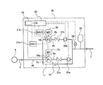
以下、本発明の実施形態について図面を参照して説明する。図1乃至図12において、同一または相当する構成要素には、同一の符号を付して重複した説明を省略する。図1は、本発明の一実施形態に係る給水装置を示す模式図である。この給水装置は、オフィスビルやマンションなどの建物に使用される直結式の給水装置である。図1に示すように、給水装置の吸込口は、導入管5を介して水道本管4に接続されている。給水装置の吐出口には配水管7が接続されており、この配水管7は、建物の内部に配置された給水器具(例えば蛇口)に連通している。給水装置は、水道本管4からの水を増圧して建物の各給水器具に水を供給する。
Embodiments of the present invention will be described below with reference to the drawings. 1 to 12, the same or corresponding components are denoted by the same reference numerals, and redundant description is omitted. FIG. 1 is a schematic view showing a water supply apparatus according to an embodiment of the present invention. This water supply apparatus is a directly connected water supply apparatus used in buildings such as office buildings and apartment buildings. As shown in FIG. 1, the suction port of the water supply apparatus is connected to the water
図1に示すように、給水装置は、導入管5を介して水道本管4に連結されるポンプ2と、このポンプ2を駆動する駆動源としての電動機(モータ)3と、ポンプ2の温度を測定する温度センサ18と、電動機3を変速可能とするインバータ21と、給水装置の給水動作(すなわちポンプ2の運転)を制御する制御部20と、ポンプ2の下流側に配置された逆止弁22と、逆止弁22の下流側に配置された流量検出器(フロースイッチ)24、吐出側圧力センサ26、および圧力タンク28と、運転情報を表示する表示器49とを備えている。本実施形態では、これら構成要素は、キャビネット30内に収容されている。一実施形態では、上記構成要素のうちいくつかのみ(例えば、制御部20およびインバータ21のみ)をキャビネット30内に収容してもよい。
As shown in FIG. 1, the water supply apparatus includes a
逆止弁22は、ポンプ2の吐出口に接続された吐出管8に設けられており、ポンプ2が停止したときの水の逆流を防止するための弁である。流量検出器24は吐出管8を流れる水の流量が所定の小水量以下であることを検出する装置である。流量検出器24は、例えば、フラップが接点と接触したことにより、水の流量が所定の小水量以下であることを検出するフラップ式流量検出器である。あるいは、流量検出器24は、例えば、フロートが接点と接触したことにより、水の流量が所定の小水量以下であることを検出するフロート式流量検出器であってもよい。吐出側圧力センサ26は、ポンプ2の吐出側圧力を測定するための水圧測定器である。圧力タンク28は、ポンプ2が停止している間の吐出側圧力を保持するための圧力保持器である。配水管7は吐出管8に接続されている。
The
ポンプ2の吸込口には吸込管9の一端が接続されており、吸込管9の他端は導入管5に接続されている。吸込管9には、図示しない逆流防止器と吸込側圧力センサが取り付けられている。逆流防止器は、水道本管4への水の逆流を確実に防止するために設置されている。
One end of the
給水装置は、ポンプ2を迂回するバイパス管11を備えている。バイパス管11の上流側端部は吸込管9に接続され、バイパス管11の下流側端部は吐出管8に接続されている。バイパス管11には逆止弁16が取り付けられており、バイパス管11内での水の逆流を防止している。このバイパス管11は、ポンプ2が停止しているときでも、流入圧のみで給水を可能とするために設けられている。
The water supply apparatus includes a
インバータ21、流量検出器24、吐出側圧力センサ26、および温度センサ18は、制御部20に信号線を介して接続されている。水の流量が所定の小水量以下になったことが流量検出器24により検出されると、制御部20はポンプ2の運転速度を一時的に上げるようインバータ21に指令を出し、圧力タンク28に蓄圧してからポンプ2の運転を停止させるようになっている(小水量停止)。一方、吐出側圧力(吐出管8内の水圧)が所定の値(始動圧力)まで低下すると、制御部20はポンプ2の運転を開始するようインバータ21に指令を出す。
The
制御部20は、インバータ21および電動機3の動作を制御することによって、ポンプ2の動作を制御する。より具体的には、制御部20は、吐出側圧力センサ26の出力信号に基づいて、ポンプ2の運転速度(すなわち回転速度)を制御する。一般的には、吐出側圧力センサ26により測定された圧力信号が設定された目標圧力と一致するようにポンプ2の運転速度を制御してポンプ2の吐出圧力が一定になるように制御する吐出圧力一定制御や、ポンプ2の吐出圧力の目標値を適切に変化させることにより給水栓における水圧を一定に制御する推定末端圧力一定制御などが行われる。
The
流量検出器24が故障すると、制御部20は、給水装置を流れる水の流量の低下を検出することができない。その結果、建物内での水の使用が停止されているにも拘わらず、ポンプ2の運転が継続される。この場合、ポンプ2は締切運転となり、過熱状態となったポンプ2が非常停止に至る場合がある。制御部20は、過熱によりポンプ2を非常停止させるための第1のしきい値を記憶しており、ポンプ2に取り付けられた温度センサ18から出力されたポンプ温度の測定値がこの第1のしきい値以上になった場合は、ポンプ2を非常停止させる。
When the
流量検出器24に異物などが付着した場合も、制御部20が給水装置を流れる水の流量の低下を検出することができないことがある。例えば、流量検出器24がフラップ式流量検出器である場合、フラップと接点との間に異物が付着すると、流量検出器24は、制御部20に水の流量の低下の検出信号を送信できない。また、フラップが接点に対してずれてしまった場合も、流量検出器24は、制御部20に水の流量の低下の検出信号を送信できない場合がある。同様に、流量検出器24がフロート式流量検出器である場合、フロートと接点との間に異物が付着すると、流量検出器24は、制御部20に水の流量の低下の検出信号を送信できない。このような流量検出器24の動作不良は、一時的な異常である。すなわち、異物が取り除かれるか、またはフラップが接点に対して正常な姿勢に戻った場合、流量検出器24は、制御部20に水の流量の低下の検出信号を送信することができる。したがって、流量検出器24をメンテナンスおよび/または交換する必要はない。
Even when foreign matter or the like adheres to the
一方で、流量検出器24の破損などの故障が発生している場合は、流量検出器24のメンテナンスおよび/または交換を促すために、流量検出器24の故障の警報を出力する必要がある。そこで、本実施形態の制御部20は、流量検出器24に異常が発生したときは、以下に説明する給水装置の運転動作を実行する。図2は、図1に示される給水装置の流量検出器24に異常が発生したときの、給水装置の運転動作を説明するためのフロー図である。
On the other hand, when a failure such as breakage of the
図2に示されるように、制御部20は、ポンプ2が運転されている間は、流量検出器24からの出力信号により、ポンプ2から吐出される水の流量が所定の小水量以下である小水量状態であるか否かを監視している(ステップ1)。流量検出器24が小水量状態を検出した場合、制御部20は、ポンプ2の運転速度を一時的に上げるようインバータ21に指令を出し、圧力タンク28に蓄圧してからポンプ2の運転を停止させる小水量停止動作を実行する(ステップ2)。流量検出器24が小水量状態を検出していない場合、ポンプ2の運転が継続される。
As shown in FIG. 2, while the
次に、制御部20は、温度センサ18により測定されたポンプ2の温度を、第1のしきい値よりも低い第2のしきい値と比較する(ステップ3)。第1のしきい値は、ポンプ2が過熱により非常停止されるポンプ2の温度であり、例えば、60℃である。第2のしきい値は、この第1のしきい値よりも低く、例えば、50℃に設定される。制御部20は、第1のしきい値および第2のしきい値を予め記憶している。ポンプ2の温度が第2のしきい値よりも低い場合、制御部20は、ステップ1に戻り流量検出器24が小水量状態を検出しているか否かを監視する。すなわち、流量検出器24が小水量状態を検出せず、かつポンプ2の温度が第2のしきい値よりも低い場合は、ポンプ2は正常に運転されていると制御部20は判断する。
Next, the
ステップ3で、ポンプ2の温度が第2のしきい値以上である場合、制御部20は、ポンプ2から吐出される水の流量が大水量状態であるか否かを決定する(ステップ4)。本明細書において、大水量状態は、ポンプ2から吐出される水の流量が所定の大水量以上である状態を意味する。制御部20は、インバータ21の電流値を監視しており、ポンプ2から吐出される水の流量が大水量状態であるか否かを決定するために、インバータ21の現在の電流値と制御部20が予め記憶している所定の電流値とを比較する。この所定の電流値は、例えば、インバータ21の定格電流値に対して70%の電流値である。インバータ21の現在の電流値が所定の電流値よりも大きい場合、制御部20は、ポンプ2から吐出される水の流量が大水量状態にあると決定し、ステップ1に戻る。インバータ21の現在の電流値が所定の電流値以下である場合、制御部20は、ポンプ2から吐出される水の流量が大水量状態にはないと決定し、ポンプ2を停止する(ステップ5)。本実施形態の以下の説明では、ステップ5でポンプ2を停止させる動作を、温度停止と称する。
When the temperature of the
ポンプ2から吐出される水の流量が大水量状態であるか否かを決定するために、制御部20は、インバータ21の現在の電力値と制御部20が予め記憶している所定の電力値とを比較してもよい。この所定の電力値は、例えば、インバータ21の定格電力値に対して70%の電力値である。さらに、ポンプ2から吐出される水の流量が大水量状態であるか否かを決定するために、制御部20は、インバータ21の現在の運転周波数と制御部20が予め記憶している所定の周波数とを比較してもよい。この所定の周波数は、例えば、インバータ21の定格周波数に対して70%の周波数である。あるいは、制御部20がポンプ2の運転速度を推定末端圧力一定制御で制御している場合は、ポンプ2から吐出される水の流量が大水量状態であるか否かを決定するために、制御部20は、現在の目標圧力と制御部20が予め記憶している所定の圧力とを比較してもよい。この所定の圧力は、例えば、大水量状態でポンプ2を運転する際の目標圧力に対して70%の圧力である。現在の目標圧力が所定の圧力以下である場合、制御部20は、ポンプ2から吐出される水の流量が大水量状態にはないと決定する。
In order to determine whether or not the flow rate of the water discharged from the
温度停止の後で、制御部20は、流量検出器24が小水量状態を検出したか否かを確認する(ステップ6)。ステップ6で、流量検出器24が小水量状態を検出した場合は、制御部20は、流量検出器24の異常カウント値を0に戻す(ステップ7)。流量検出器24が小水量状態を検出しない場合は、制御部20は、圧力センサ26により測定されているポンプ2の吐出側圧力が低下するか否かを確認する(ステップ8)。ポンプ2が停止されている状態でポンプ2の吐出側圧力が低下しないということは、水が給水装置内を流れていない(すなわち、建物で水が使用されていない)ことを示している。したがって、制御部20は、流量検出器24に異常が発生していると判断し、流量検出器24の異常カウント値に1を加算する(ステップ9)。
After the temperature stop, the
次に、制御部20は、該制御部20に予め記憶された設定値と流量検出器24の異常カウント値とを比較する(ステップ10)。この設定値は、好ましくは、5から10の間の数値に設定される。流量検出器24の異常カウント値が設定値に到達した場合、制御部20は、流量検出器24の故障の警報を出力する(ステップ11)。流量検出器24の故障の警報が出力されていても、制御部20は、ポンプ2の吐出側圧力が始動圧力まで低下したとき(すなわち、ポンプ2の始動条件が成立したとき:ステップ12)に、ポンプ2の運転を開始する(ステップ13)。さらに、ステップ8で、ポンプ2の吐出側圧力が低下した場合と、ステップ10で、流量検出器24の異常カウント値が設定値に到達していない場合も、制御部20は、ポンプ2の吐出側圧力が始動圧力まで低下したときに、ポンプ2の運転を開始する。ステップ13でポンプ2の運転が開始されると、制御部20は、流量検出器24からの出力信号に基づいて、ポンプ2から吐出される水の流量が所定の小水量以下であるか否かを監視する(ステップ1)。
Next, the
このように、本実施形態では、流量検出器24の異常カウント値が設定値に到達するまで、流量検出器24の故障の警報を出力せずに、ポンプ2の始動と停止とを繰り返す。このポンプ2の始動と停止の繰り返しにより、流量検出器24に付着した異物などが取り除かれた場合は、流量検出器24はステップ1で正常に小水量状態を検出し、ステップ7で流量検出器24の異常カウント値が0に戻される。したがって、流量検出器24の一時的な動作不良は、流量検出器24の故障としてユーザーに伝わらないので、流量検出器24のメンテナンスおよび/または交換の頻度を低減することができる。一方で、流量検出器24の異常カウント値が設定値に到達したときには、流量検出器24に破損などの故障が発生していると考えられる。したがって、制御部20は、流量検出器24の故障の警報を出力し、ユーザーに流量検出器24のメンテナンスおよび/または交換を促す。このように、本実施形態によれば、流量検出器24の故障を確実に検出することができる。
Thus, in the present embodiment, the
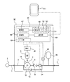
図3は、本発明の他の実施形態に係る給水装置を示す模式図である。図3に示される給水装置は、2組のポンプ2a,2b、電動機3a,3b、温度センサ18a,18b、インバータ21a,21b、逆止弁22a,22b、および流量検出器24a,24bを備えている。本実施形態では、給水装置は、2組のポンプ2a,2b、電動機3a,3b、温度センサ18a,18b、インバータ21a,21b、逆止弁22a,22b、および流量検出器24a,24bを備えているが、3組以上のポンプ、電動機、温度センサ、インバータ、逆止弁、および流量検出器を備えてもよい。特に説明しない本実施形態の構成は、図1に示される実施形態の構成と同一であるため、その重複する説明を省略する。
FIG. 3 is a schematic view showing a water supply apparatus according to another embodiment of the present invention. The water supply apparatus shown in FIG. 3 includes two sets of
図3に示される給水装置は、第1のポンプ2aおよび第2のポンプ2bと、第1のポンプ2aを駆動するための第1の電動機3a、および第2のポンプ2aを駆動するための第2の電動機3bと、第1の電動機3aを変速可能とする第1のインバータ21a、および第2の電動機3bを変速可能とする第2のインバータ21bと、第1のポンプ2aおよび第2のポンプ2bの吐出側圧力を測定する圧力センサ26と、第1のポンプ2aから吐出される水の流量が所定の小水量以下である小水量状態を検出する第1の流量検出器24a、および第2のポンプ2bから吐出される水の流量が所定の小水量以下である小水量状態を検出する第2の流量検出器24bと、第1のポンプ2aの温度を測定する温度センサ18a、および第2のポンプ2bの温度を測定する温度センサ18bと、第1のポンプ2aおよび第2のポンプ2bの運転を制御する制御部20と、を備える。インバータ21a,21b、流量検出器24a,24b、吐出側圧力センサ26、および温度センサ18a,18bは、制御部20に信号線を介して接続されている。
The water supply device shown in FIG. 3 includes a
第1のポンプ2aおよび第2のポンプ2bが停止している状態で、建物内で水が使用されると、第1のポンプ2aおよび第2のポンプ2bの吐出側圧力が低下する。この吐出側圧力、すなわち吐出側圧力センサ26の出力値が所定の始動圧力にまで低下すると、制御部20はポンプ2a,2bのうちのいずれか一方を始動させる。以下では、第1のポンプ2aが始動される実施形態が説明される。第1のポンプ2aの運転中は、吐出側圧力センサ26の出力値に基づいて推定末端圧力一定制御または吐出圧力一定制御が行われる。
When water is used in the building in a state where the
建物での水の使用が停止されると、第1のポンプ2aから吐き出される水の流量が低下する。第1のポンプ2aからの水の流量が所定の小水量以下になったことが第1の流量検出器24aにより検出されると、制御部20は第1のポンプ2aの運転速度を一時的に上げるように第1のインバータ21aに指令を出し、圧力タンク28に蓄圧してから第1のポンプ2aの運転を停止させるようになっている(小水量停止)。一方、吐出側圧力が所定の始動圧力まで低下すると、制御部20は第2のポンプ2bの運転を開始するよう第2のインバータ21bに指令を出す。第2のポンプ2bの運転中は、吐出側圧力センサ26の出力値に基づいて推定末端圧力一定制御または吐出圧力一定制御が行われる。
When the use of water in the building is stopped, the flow rate of water discharged from the
図4は、図3に示される給水装置の一方の流量検出器24aに異常が発生したときの、給水装置の運転動作を説明するためのフロー図である。図4に示されるように、制御部20は、第1のポンプ2aが運転されている間は、第1の流量検出器24aからの出力信号により、第1のポンプ2aから吐出される水の流量が所定の小水量以下である小水量状態であるか否かを監視している(ステップ1)。第1の流量検出器24aが小水量状態を検出した場合、制御部20は、第1のポンプ2aの運転速度を一時的に上げるよう第1のインバータ21aに指令を出し、圧力タンク28に蓄圧してから第1のポンプ2aの運転を停止させる小水量停止動作を実行する(ステップ2)。第1の流量検出器24aが小水量状態を検出していない場合、第1のポンプ2aの運転が継続される。
FIG. 4 is a flowchart for explaining the operation of the water supply apparatus when an abnormality occurs in one
次に、制御部20は、第1の温度センサ18aにより測定された第1のポンプ2aの温度を、第1のしきい値よりも低い第2のしきい値と比較する(ステップ3)。第1のしきい値は、第1のポンプ2aが過熱により非常停止されるポンプ2の温度であり、例えば、60℃である。第2のしきい値は、この第1のしきい値よりも低く、例えば、50℃に設定される。制御部20は、第1のしきい値および第2のしきい値を予め記憶している。第1のポンプ2aの温度が第2のしきい値よりも低い場合、制御部20は、ステップ1に戻り、第1の流量検出器24aが小水量状態を検出しているか否かを監視する。すなわち、第1の流量検出器24aが小水量状態を検出せず、かつ第1のポンプ2aの温度が第2のしきい値よりも低い場合は、第1のポンプ2aは正常に運転されていると制御部20は判断する。
Next, the
ステップ3で、第1のポンプ2aの温度が第2のしきい値以上である場合、制御部20は、第1のポンプ2aから吐出される水の流量が大水量状態であるか否かを決定する(ステップ4)。上述した実施形態と同様に、大水量状態は、第1のポンプ2aから吐出される水の流量が所定の大水量以上である状態を意味する。制御部20は、第1のインバータ21aの電流値を監視しており、第1のポンプ2aから吐出される水の流量が大水量状態であるか否かを決定するために、第1のインバータ21aの現在の電流値と制御部20が予め記憶している所定の電流値とを比較する。この所定の電流値は、例えば、第1のインバータ21aの定格電流値に対して70%の電流値である。第1のインバータ21aの現在の電流値が所定の電流値よりも大きい場合、制御部20は、第1のポンプ2aから吐出される水の流量が大水量状態にあると決定し、ステップ1に戻る。第1のインバータ21aの現在の電流値が所定の電流値以下である場合、制御部20は、第1のポンプ2aから吐出される水の流量が大水量状態にはないと決定し、待機中の第2のポンプ2bを始動させ(ステップ5)、第1のポンプ2aを停止する(ステップ6)。第2のポンプ2bを始動させるのと同時に、第1のポンプ2aを停止させてもよい。本実施形態の以下の説明では、ステップ6で第1のポンプ2aを停止させる動作を、温度停止と称する。
In
第1のポンプ2aから吐出される水の流量が大水量状態であるか否かを決定するために、制御部20は、第1のインバータ21aの現在の電力値と制御部20が予め記憶している所定の電力値とを比較してもよい。この所定の電力値は、例えば、第1のインバータ21aの定格電力値に対して70%の電力値である。さらに、第1のポンプ2aから吐出される水の流量が大水量状態であるか否かを決定するために、制御部20は、第1のインバータ21aの現在の運転周波数と制御部20が予め記憶している所定の周波数とを比較してもよい。この所定の周波数は、例えば、第1のインバータ21aの定格周波数に対して70%の周波数値である。あるいは、制御部20が第1のポンプ2aの運転速度を推定末端圧力一定制御で制御している場合は、第1のポンプ2aから吐出される水の流量が大水量状態であるか否かを決定するために、制御部20は、現在の目標圧力と制御部20が予め記憶している所定の圧力とを比較してもよい。この所定の圧力は、例えば、大水量状態で第1のポンプ2aを運転する際の目標圧力に対して70%の圧力である。現在の目標圧力が所定の圧力以下である場合、制御部20は、第1のポンプ2aから吐出される水の流量が大水量状態にはないと決定する。
In order to determine whether or not the flow rate of the water discharged from the
温度停止の後で、制御部20は、第1の流量検出器24aが小水量状態を検出したか否かを確認する(ステップ7)。ステップ7で、第1の流量検出器24aが小水量状態を検出した場合は、制御部20は、第1の流量検出器24aの異常カウント値を0に戻す(ステップ8)。第1の流量検出器24aが小水量状態を検出しない場合は、制御部20は、第2の流量検出器24bが第2のポンプ2bから吐出される水の流量が所定の小水量以下である小水量状態を検出しているか否かを確認する(ステップ9)。第2の流量検出器24bが小水量状態を検出したということは、水が給水装置内を流れていない(すなわち、建物で水が使用されていない)ことを示している。したがって、制御部20は、第1の流量検出器24aに異常が発生していると判断し、第1の流量検出器24aの異常カウント値に1を加算する(ステップ10)。
After the temperature stop, the
次に、制御部20は、該制御部20に予め記憶された設定値と第1の流量検出器24aの異常カウント値とを比較する(ステップ11)。この設定値は、好ましくは、5から10の間の数値に設定される。第1の流量検出器24aの異常カウント値が設定値に到達した場合、制御部20は、第1の流量検出器24aの故障の警報を出力する(ステップ12)。第1の流量検出器24aの故障の警報が出力されていても、制御部20は、ポンプ2aの吐出側圧力が所定の始動圧力まで低下したとき(すなわち、第1ポンプ2aの始動条件が成立したとき:ステップ13)に、第1のポンプ2aの運転を開始する(ステップ14)。さらに、ステップ9で、第2の流量検出器24bが小水量状態を検出しなかった場合と、ステップ11で、第1の流量検出器24aの異常カウント値が設定値に到達していない場合も、制御部20は、第1のポンプ2aの吐出側圧力が所定の始動圧力まで低下したときに、第1のポンプ2aの運転を開始する。ステップ14で第1のポンプ2aの運転が開始されると、制御部20は、流量検出器24からの出力信号に基づいて、第1のポンプ2aから吐出される水の流量が所定の小水量以下であるか否かを監視する(ステップ1)。
Next, the
このように、本実施形態では、第1の流量検出器24aの異常カウント値が設定値に到達するまで、第1の流量検出器24aの故障の警報を出力せずに、第1のポンプ2aの始動と停止とを繰り返す。この第1のポンプ2aの始動と停止の繰り返しにより、第1の流量検出器24aに付着した異物などが取り除かれた場合は、第1の流量検出器24aはステップ1で正常に小水量状態を検出し、ステップ8で第1の流量検出器24aの異常カウント値が0に戻される。したがって、第1の流量検出器24aの一時的な動作不良は、第1の流量検出器24aの故障としてユーザーに伝わらないので、第1の流量検出器24aのメンテナンスおよび/または交換の頻度を低減することができる。一方で、第1の流量検出器24aの異常カウント値が設定値に到達したときには、第1の流量検出器24aに破損などの故障が発生していると考えられる。したがって、制御部20は、第1の流量検出器24aの故障の警報を出力し、ユーザーに第1の流量検出器24aのメンテナンスおよび/または交換を促す。このように、本実施形態によれば、第1の流量検出器24aの故障を確実に検出することができる。
As described above, in this embodiment, the
次に、図1に示される給水装置の制御部20のより詳細な構成について図5を参照して説明する。図5に示すように、給水装置は、温度停止が実行されていること、および/または流量検出器24が故障していることを含む運転情報を表示する表示器49をさらに備えている。制御部20は、設定部46、記憶部47、演算部48、I/O部50、および運転パネル51を備えている。運転パネル51は、ヒューマンインターフェースとして機能する。設定部46には、ポンプ2の運転制御に関する各種設定値が入力される。設定部46および表示器49は、運転パネル51に設けられている。表示器49は液晶パネルであり、設定部46はタッチパネル式操作器でもよい。本実施形態では、表示器49は制御部20に取り付けられているが、表示器49は制御部20から離れて配置されてもよい。また、表示器49は液晶パネルと7セグメントLEDや表示灯を組み合わせた構成でもよい。
Next, the more detailed structure of the
記憶部47は、温度停止の実行の履歴、および/または流量検出器24の故障の履歴などを記憶する。演算部48としては、CPUが使用される。表示器49は、ヒューマンインターフェースとして機能し、温度停止が実行されていること、および/または流量検出器24が故障していることを含む運転情報を表示する。ユーザーは、設定部46上のクリアボタン53を押すことにより、表示器49での表示を消去することができる。
The
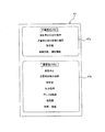
図6は記憶部47の詳細を示す図である。図6に示すように、記憶部47は、不揮発性メモリから構成された不揮発性記憶領域47aと、揮発性メモリから構成された揮発性記憶領域47bを備えている。不揮発性記憶領域47aは、温度停止の実行の履歴、流量検出器24の故障の履歴、ポンプ2の運転に必要な各種設定値、故障履歴、運転履歴などを記憶する領域である。揮発性記憶領域47bは、温度停止の実行、および/または流量検出器24の故障だけでなく、圧力信号、ポンプ回転数、電流値、故障、警報などを記憶する領域である。
FIG. 6 is a diagram showing details of the
図7は給水装置の他の実施形態を示す図である。本実施形態では、表示器49に加えて、外部表示器61がさらに設けられている。図7に示すように、制御部20は通信部60をさらに備えている。制御部20は有線通信または無線通信によって外部表示器61に接続されている。外部表示器61として、例えばスマートフォンや携帯電話、パソコン、タブレットの汎用端末機器または遠隔監視器などの専用端末機器が採用される。本実施形態では、表示器49は7セグメントLEDや表示灯などの簡易な表示器であり、外部表示器61は液晶画面と液晶画面のタッチ入力方式や押圧ボタン方式用いた高機能表示器である。簡易な表示器49に比べて外部表示器61は表示できる情報量が格段に多いため、外部表示器61に温度停止が実行されていること、および/または流量検出器24が故障していることを表示することによって、給水装置に不慣れなユーザーは誤解することなく、温度停止が実行されていること、および/または流量検出器24が故障していることを認識することが出来る。
FIG. 7 is a view showing another embodiment of the water supply apparatus. In the present embodiment, in addition to the
給水装置は機械室やポンプ室などの電気的なノイズの多い環境に設置されることがある。本実施形態によれば、給水装置に組み込まれる表示器49として、液晶表示やタッチパネルよりも電気的ノイズに強い7セグメントLEDや表示灯、機械的な押圧ボタンなどにて構成された表示器を使用することにより、外部環境から発生される電気的なノイズにより外部表示器61の液晶表示やタッチパネル操作に異常が発生した場合でも、表示器49により給水装置の運転に必要な最低限度の表示や操作を行うことが可能なため、給水装置を電気的ノイズの多い環境下にも設置することができる。さらに、外部表示器61として、スマートフォン、携帯電話、パソコン、タブレットなどの汎用端末機器を使用すると、ユーザーは専用のアプリケーションソフトウエアを用いて、温度停止が実行されていること、および/または流量検出器24が故障していることを表示させることができるため、専用のアプリケーションソフトウエアを複数用意し使い分けることによりユーザーのレベルに沿った温度停止の実行、および/または流量検出器24の故障の表示を提供することが可能である。
The water supply apparatus may be installed in an environment with a lot of electrical noise such as a machine room or a pump room. According to the present embodiment, as the
図8は給水装置のさらに他の実施形態を示す図である。本実施形態では、制御部20に表示器49は設けられていなく、代わりに外部表示器(高機能表示器)61のみが設けられる。その他の構成は、図7に示す実施形態と同様である。図8に示す実施形態によれば、給水装置には表示器自体を設ける必要がなくなるので、給水装置全体のコストを更に下げることが可能である。
FIG. 8 is a view showing still another embodiment of the water supply apparatus. In the present embodiment, the
図9は給水装置のさらに他の実施形態を示す図である。図9において、表示器49は7セグメントLEDや表示灯などの簡易な表示器である。通信部60は公衆回線を介して保守管理会社または管理人室に設けられた外部表示器65に接続されている。制御部20は、温度停止が実行されていること、および/または流量検出器24が故障していることを判断し、外部表示器65は制御部20に公衆回線を通じて定期的に通信し、温度停止が実行されているか否か、および/または流量検出器24が故障しているか否かを制御部20に問い合わせる。そして、温度停止が実行されている場合、および/または流量検出器24が故障している場合は、外部表示器65は温度停止が実行されていること、および/または流量検出器24が故障していることを表示する。外部表示器65は温度停止が実行されていること、および/または流量検出器24が故障していることを他の情報に追加的に表示してもよい。
FIG. 9 is a view showing still another embodiment of the water supply apparatus. In FIG. 9, the
本実施形態の制御部20は、図5に示すクリアボタン53を備えていなく、代わりに、外部表示器65は、図9に示すように、クリアボタン66を備えている。ユーザーがこのクリアボタン66を押すと、外部表示器65上に表示されている温度停止の実行、および/または流量検出器24の故障の表示が消去される。
The
図10は給水装置のさらに他の実施形態を示す図である。本実施形態の制御部20の基本的構成は図8に示す実施形態の制御部20の構成と同じであるが、制御部20が通信部60に代えて、制御部側アンテナ部67を備えている点、および制御部側アンテナ部67に接続された集積回路68を備えている点で異なっている。集積回路68は、不揮発性記憶領域47a、揮発性記憶領域47bを有する記憶部47に電気的に接続されている。なお、本実施形態の制御部20は表示器49を備えていないが、制御部20に表示器49を設けてもよい。
FIG. 10 is a view showing still another embodiment of the water supply apparatus. The basic configuration of the
外部表示器70は、電波を送受信する表示器側アンテナ部71と、表示器側アンテナ部71で受信したデータを読み取るデータリーダー74と、データリーダー74によって読み取られたデータ(例えば、温度停止の実行、流量検出器24の故障、ポンプ2の運転状態、吐出し圧力など)を表示する表示部72と、データリーダー74、表示器側アンテナ部71、および表示部72に電力を供給するバッテリー73とを備えている。外部表示器70として、例えばスマートフォンや携帯電話、パソコン、タブレット等の汎用端末機器でもよく、遠隔監視器などの専用の端末機器でもよい。特に、スマートフォンなどの汎用端末機器を外部表示器として使用すれば、専用の表示器を制作するコストが削減できるので、給水装置のコストを下げることができる。また、複数のユーザーが個々の汎用端末機器に温度停止の実行、および/または流量検出器24の故障を表示させることができるので、マンションやビルの管理人のような給水装置に関する専門知識のないユーザーに対しても、温度停止が実行されていること、および/または流量検出器24が故障していることを分かり易く知らせることができる給水装置を安価に提供することができる。
The
外部表示器70は、近距離無線通信(NFC:Near Field Communication)の技術によって制御部20と接続される。より具体的には、外部表示器70を制御部20に近づけた状態で、表示器側アンテナ部71が電波を発生すると、その電波を制御部側アンテナ部67が受け取り、制御部側アンテナ部67は電波を電力に変換する。この電力は集積回路68および記憶部47に供給されてこれら集積回路68および記憶部47を駆動する。集積回路68は記憶部47に記憶されている上記データを読み取り、制御部側アンテナ部67にデータを送る。制御部側アンテナ部67は、データとともに電波を表示器側アンテナ部71に送信する。データリーダー74は、表示器側アンテナ部71が受信したデータを読み取り、そのデータを表示部72に表示させる。
The
外部表示器70は、温度停止の実行、および/または流量検出器24の故障の表示を消去するためのクリアボタン66を備えている。ユーザーがこのクリアボタン66を押すと、表示部72に表示されている温度停止の実行、および/または流量検出器24の故障の表示が消去される。本実施形態のクリアボタン66は、表示部72の画面上に現れる仮想的なボタンであるが、クリアボタン66は表示部72の外に設けられた機械的なボタンであってもよい。本実施形態の制御部20はクリアボタンを備えていないが、制御部20にクリアボタンを設けてもよい。なお、これらの操作には、操作制限を設けてもよい。具体的には、ユーザーが主に使用する外部表示器70にクリアボタン66を設け、メンテナンス員が主に使用する制御部20にリセットボタン52を設ける。このように制御部20にのみリセットボタン52を設けることで、ユーザーのリセットボタン52の誤操作を防ぐことができる。パスワード等の複雑な使用制限の解除方法ではなく、外部表示器70を設けることで、ユーザーの誤操作による温度停止の実行、および/または流量検出器24の故障のクリアを防止することができる。
The
本実施形態では、外部表示器70と制御部20との間で無線通信が行われ、記憶部47に記憶されている温度停止の実行、および/または流量検出器24の故障などを含むデータは、制御部20から外部表示器70に送られる。本実施形態によれば、給水装置の電源が入っていない場合でも、制御部側アンテナ部67は外部表示器70から発せられる電波から電力を発生し、集積回路68および記憶部47を駆動することができる。したがって、給水装置のメンテンナンス中などにおいて制御部20に電力が供給されていないときでも、外部表示器70は、制御部20の記憶部47から温度停止の実行の履歴、および/または流量検出器24の故障の履歴を含むデータを取得し、該データを表示することができる。
In the present embodiment, wireless communication is performed between the
制御部20が故障した場合には新制御部20に交換する必要がある。この制御部20の交換時に、故障した旧制御部20はすでに電源が入らない状態においても、本実施形態では、旧制御部20の温度停止の実行の履歴、および/または流量検出器24の故障の履歴に関するデータを新制御部20の記憶部47に継承することが可能となる。具体的には、旧制御部20の記憶部47の該データを外部表示器70にて表示し、その表示を確認しながらメンテナンス員が新制御部20の操作部より入力し、新制御部20の記憶部47に該データを記憶させてもよいし、旧制御部20の該データを外部表示器70にて取得し、外部表示器70から新しい制御部20の記憶部47へと通信手段にて書き込んでもよい。制御部20が電源が入らない状態で故障しても、不揮発性記憶領域47aに記憶されているデータを新制御部20の記憶部47に継承できるので、温度停止の実行の履歴、および/または流量検出器24の故障の履歴のデータが損失されることない。これは、給水装置が新制御部20にて自動運転を開始した後でも、温度停止の実行の履歴、および/または流量検出器24の故障の履歴を表示することができることを意味する。
When the
本実施形態によれば、給水装置に電力が供給されていないときでも、ユーザーやメンテナンス員が外部表示器70を制御部20に近づけるだけで、記憶部47から温度停止の実行の履歴、および/または流量検出器24の故障の履歴を含む情報を取得することが可能である。
According to the present embodiment, even when power is not supplied to the water supply device, the user or the maintenance staff simply brings the
本実施形態で採用される近距離無線通信(NFC:Near Field Communication)は、数cmの近距離でのみ相互通信が可能な技術である。したがって、外部表示器70に温度停止の実行、および/または流量検出器24の故障やその他の各種情報を表示させるためには、ユーザーやメンテナンス員は外部表示器70を制御部20に近づける必要がある。このことは、外部表示器70を操作するときは、ユーザーやメンテナンス員は給水装置の近くにいることを意味する。したがって、ユーザーやメンテナンス員は給水装置を目視しながら外部表示器70を操作することになり、誤操作に起因した給水装置の予期しない動作を防止することに繋がる。また、複数の給水装置が設置された現場では、温度停止の実行、および/または流量検出器24の故障を表示したい給水装置の近距離でのみ通信可能となる為、無線通信にてよくある意図しない別の給水装置の温度停止の実行、および/または流量検出器24の故障を表示してしまうという誤表示を防止することが出来る。
Near field communication (NFC) employed in the present embodiment is a technology that enables mutual communication only at a short distance of several centimeters. Therefore, in order to display the execution of the temperature stop and / or the failure of the
図11は給水装置のさらに他の実施形態を示す図である。本実施形態では、制御部20は通信部60を備えている。通信部60は、有線通信または無線通信によって外部表示器75の通信部76に接続されている。外部表示器75は制御部80を備えており、制御部80は通信部76、記憶部77、演算部78、および表示部79を備えている。制御部20は、表示器49を備えていてもよい。また、記憶部77は記憶部47と同様に図6の構成とする。
FIG. 11 is a view showing still another embodiment of the water supply apparatus. In the present embodiment, the
図12は給水装置のさらに他の実施形態を示す図である。本実施形態では、制御部20には表示器は設けられておらず、代わりに、外部表示器75に表示部79と設定部82が設けられている。その他の構成は図11に示す実施形態と同様である。本実施形態では、温度停止の実行、および/または流量検出器24の故障の状態は表示部79に表示され、その他各種設定値の入力は、外部表示器75の設定部82を通じて行われる。
FIG. 12 is a view showing still another embodiment of the water supply apparatus. In the present embodiment, the
上述した実施形態に係る給水装置は、水道本管4に直接接続される直結式の給水装置であるが、本発明の給水装置は、受水槽を介して水道本管4に接続される受水槽式の給水装置であってもよい。
Although the water supply apparatus which concerns on embodiment mentioned above is a direct connection type water supply apparatus directly connected to the water
上述した実施形態は、本発明が属する技術分野における通常の知識を有する者が本発明を実施できることを目的として記載されたものである。上記実施形態の種々の変形例は、当業者であれば当然になしうることであり、本発明の技術的思想は他の実施形態にも適用しうる。したがって、本発明は、記載された実施形態に限定されることはなく、特許請求の範囲によって定義される技術的思想に従った最も広い範囲とすべきである。 The embodiment described above is described for the purpose of enabling the person having ordinary knowledge in the technical field to which the present invention belongs to implement the present invention. Various modifications of the above embodiment can be naturally made by those skilled in the art, and the technical idea of the present invention can be applied to other embodiments. Therefore, the present invention should not be limited to the described embodiments, but should be the widest scope according to the technical idea defined by the claims.
2 ポンプ
3 電動機
4 水道本管
5 導入管
7 配水管
8 吐出管
9 吸込管
11 バイパス管
16 逆止弁
18 温度センサ
20 制御部
21 インバータ
22 逆止弁
26 圧力センサ
28 圧力タンク
30 キャビネット
46 設定部
47 記憶部
47a 不揮発性記憶領域
47b 揮発性記憶領域
48 演算部
49 表示部
50 I/O部
51 運転パネル
52 リセットボタン
53,66 クリアボタン
60 通信部
61,65,70,75 外部表示器
67 制御部側アンテナ部
68 集積回路
71 表示器側アンテナ部
72 表示部
73 バッテリー
74 データリーダー
79 表示部
82 設定部
2 pump 3
Claims (12)
前記ポンプを駆動するための電動機と、
前記ポンプの吐出側圧力を測定する圧力センサと、
前記ポンプから吐出される水の流量が所定の小水量以下である小水量状態を検出する流量検出器と、
前記ポンプの温度を測定する温度センサと、
前記ポンプの運転を制御する制御部と、を備え、
前記制御部は、
前記ポンプの測定温度が、前記ポンプを非常停止させる第1のしきい値よりも低い第2のしきい値以上であり、かつ前記ポンプから吐出される水の流量が大水量状態ではないときに、前記ポンプを停止させる温度停止を実行し、
前記温度停止の後で、前記流量検出器が前記小水量状態を検出せず、かつ前記吐出側圧力が低下しない場合は、前記流量検出器の異常カウント値に1を加算し、
前記異常カウント値が設定値に到達した場合は、前記流量検出器の故障の警報を出力することを特徴とする給水装置。 A pump,
An electric motor for driving the pump;
A pressure sensor for measuring the discharge side pressure of the pump;
A flow rate detector for detecting a small water amount state in which a flow rate of water discharged from the pump is equal to or less than a predetermined small water amount;
A temperature sensor for measuring the temperature of the pump;
A control unit for controlling the operation of the pump,
The controller is
When the measured temperature of the pump is equal to or higher than a second threshold value that is lower than the first threshold value for emergency stop of the pump, and the flow rate of water discharged from the pump is not in a large water amount state Perform a temperature stop to stop the pump,
After the temperature stop, when the flow rate detector does not detect the small water amount state and the discharge side pressure does not decrease, add 1 to the abnormal count value of the flow rate detector,
When the abnormal count value reaches a set value, an alarm for failure of the flow rate detector is output.
前記制御部は、前記インバータの電流値が所定の電流値以下であるか、前記インバータの消費電力が所定の電力値以下であるか、または前記インバータの運転周波数が所定の周波数以下である場合か、または推定末端圧力一定制御時の現在の目標圧力が所定の圧力以下である場合は、前記ポンプから吐出される水の流量が前記大水量状態ではないと決定することを特徴とする請求項1または2に記載の給水装置。 Further comprising an inverter that enables the electric motor to shift,
Whether the current value of the inverter is equal to or lower than a predetermined current value, whether the power consumption of the inverter is equal to or lower than a predetermined power value, or whether the operating frequency of the inverter is equal to or lower than a predetermined frequency Or when the current target pressure at the time of constant control of the estimated terminal pressure is equal to or lower than a predetermined pressure, the flow rate of water discharged from the pump is determined not to be in the large water amount state. Or the water supply apparatus of 2.
前記第1のポンプを駆動するための第1の電動機、および前記第2のポンプを駆動するための第2の電動機と、
前記第1のポンプおよび第2のポンプの吐出側圧力を測定する圧力センサと、
前記第1のポンプから吐出される水の流量が所定の小水量以下である小水量状態を検出する第1の流量検出器、および前記第2のポンプから吐出される水の流量が所定の小水量以下である小水量状態を検出する第2の流量検出器と、
前記第1のポンプの温度を測定する温度センサと、
前記第1のポンプおよび前記第2のポンプの運転を制御する制御部と、を備え、
前記制御部は、
前記第1のポンプの測定温度が前記第1のポンプを非常停止させる第1のしきい値よりも低い第2のしきい値以上であり、かつ前記第1のポンプから吐出される水の流量が大水量状態ではないときに、前記第1のポンプを停止させる温度停止を実行し、
前記温度停止の前、または前記温度停止と同時に、前記第2のポンプを始動させ、
前記第2のポンプを始動させた後で、前記第1の流量検出器が前記小水量状態を検出せず、かつ前記第2の流量検出器が前記小水量状態を検出した場合は、前記第1の流量検出器の異常カウント値に1を加算し、
前記異常カウント値が設定値に到達した場合は、前記第1の流量検出器の故障の警報を出力することを特徴とする給水装置。 A first pump and a second pump;
A first electric motor for driving the first pump, and a second electric motor for driving the second pump;
A pressure sensor for measuring a discharge side pressure of the first pump and the second pump;
A first flow rate detector for detecting a small water amount state in which a flow rate of water discharged from the first pump is equal to or less than a predetermined small water amount, and a flow rate of water discharged from the second pump is a predetermined small amount A second flow rate detector that detects a small water volume state that is less than or equal to the water volume;
A temperature sensor for measuring the temperature of the first pump;
A controller that controls the operation of the first pump and the second pump,
The controller is
The measured temperature of the first pump is equal to or higher than a second threshold value that is lower than the first threshold value for emergency stop of the first pump, and the flow rate of water discharged from the first pump. A temperature stop to stop the first pump when
Starting the second pump before or simultaneously with the temperature stop,
If the first flow rate detector does not detect the small water amount state after the second pump is started, and the second flow rate detector detects the small water amount state, 1 is added to the abnormal count value of the flow rate detector of 1,
When the abnormal count value reaches a set value, the water supply device outputs a warning of failure of the first flow rate detector.
前記制御部は、前記インバータの電流値が所定の電流値以下であるか、前記インバータの消費電力が所定の電力値以下であるか、または前記インバータの運転周波数が所定の周波数以下である場合か、または推定末端圧力一定制御時の現在の目標圧力が所定の圧力以下である場合は、前記第1のポンプから吐出される水の流量が前記大水量状態ではないと決定することを特徴とする請求項4または5に記載の給水装置。 An inverter that enables the first electric motor to shift,
Whether the current value of the inverter is equal to or lower than a predetermined current value, whether the power consumption of the inverter is equal to or lower than a predetermined power value, or whether the operating frequency of the inverter is equal to or lower than a predetermined frequency Or, when the current target pressure at the time of constant control of the estimated terminal pressure is equal to or lower than a predetermined pressure, it is determined that the flow rate of water discharged from the first pump is not in the large water amount state. The water supply apparatus of Claim 4 or 5.
前記集積回路は、前記記憶部から前記データを読み取り、前記制御部側アンテナ部は前記データを前記外部表示器に送信することを特徴とする請求項10に記載の給水装置。 The control unit stores data indicating an execution history of the temperature stop and / or a failure history of the flow rate detector in the storage unit,
The water supply device according to claim 10, wherein the integrated circuit reads the data from the storage unit, and the control unit side antenna unit transmits the data to the external display.
前記温度停止の後で、前記ポンプから吐出される水の流量が所定の小水量値以下である小水量状態を検出する流量検出器が前記小水量状態を検出せず、かつ圧力センサによって測定される前記ポンプの吐出側圧力が低下しない場合は、前記流量検出器の異常カウント値に1を加算し、
前記異常カウント値が設定値に到達した場合は、前記流量検出器の故障の警報を出力することを特徴とする給水装置の運転方法。 During the operation of the pump, the measured temperature of the pump is equal to or higher than a second threshold value that is lower than the first threshold value for emergency stop of the pump, and the flow rate of water discharged from the pump is large. Perform a temperature stop to stop the pump when not in a state;
After the temperature stop, a flow rate detector that detects a small water amount state in which the flow rate of water discharged from the pump is equal to or less than a predetermined small water amount value does not detect the small water amount state and is measured by a pressure sensor. When the discharge side pressure of the pump does not decrease, 1 is added to the abnormal count value of the flow rate detector,
When the abnormal count value reaches a set value, an alarm for failure of the flow rate detector is output.
Priority Applications (1)
| Application Number | Priority Date | Filing Date | Title |
|---|---|---|---|
| JP2016018495A JP6643117B2 (en) | 2016-02-03 | 2016-02-03 | Water supply device and method of operating water supply device |
Applications Claiming Priority (1)
| Application Number | Priority Date | Filing Date | Title |
|---|---|---|---|
| JP2016018495A JP6643117B2 (en) | 2016-02-03 | 2016-02-03 | Water supply device and method of operating water supply device |
Publications (2)
| Publication Number | Publication Date |
|---|---|
| JP2017137799A true JP2017137799A (en) | 2017-08-10 |
| JP6643117B2 JP6643117B2 (en) | 2020-02-12 |
Family
ID=59565613
Family Applications (1)
| Application Number | Title | Priority Date | Filing Date |
|---|---|---|---|
| JP2016018495A Active JP6643117B2 (en) | 2016-02-03 | 2016-02-03 | Water supply device and method of operating water supply device |
Country Status (1)
| Country | Link |
|---|---|
| JP (1) | JP6643117B2 (en) |
Cited By (4)
| Publication number | Priority date | Publication date | Assignee | Title |
|---|---|---|---|---|
| JP2021093821A (en) * | 2019-12-10 | 2021-06-17 | 株式会社荏原製作所 | Water supply device, control device, and inverter |
| JP2021183816A (en) * | 2020-05-21 | 2021-12-02 | 株式会社川本製作所 | Feed water supply system |
| US11768929B2 (en) | 2019-09-04 | 2023-09-26 | Blue-White Industries, Ltd. | Lockout system for metering pump |
| JP2024176538A (en) * | 2023-06-08 | 2024-12-19 | 株式会社日立産機システム | Water supply device and water supply method |
Citations (6)
| Publication number | Priority date | Publication date | Assignee | Title |
|---|---|---|---|---|
| JPH02183819A (en) * | 1989-01-11 | 1990-07-18 | Nec Corp | Detecting mechanism for flow rate abnormality of cooling device |
| JPH09268978A (en) * | 1996-04-01 | 1997-10-14 | Ebara Corp | Variable speed water supply |
| JP2005291180A (en) * | 2004-04-05 | 2005-10-20 | Ebara Corp | Pump device |
| JP2006169962A (en) * | 2004-12-10 | 2006-06-29 | Ebara Corp | Pump start frequency abnormality detection method and water supply device |
| JP2009008035A (en) * | 2007-06-29 | 2009-01-15 | Ebara Corp | Variable speed water supply device |
| JP2015025427A (en) * | 2013-07-26 | 2015-02-05 | 株式会社荏原製作所 | Water supply equipment |
-
2016
- 2016-02-03 JP JP2016018495A patent/JP6643117B2/en active Active
Patent Citations (6)
| Publication number | Priority date | Publication date | Assignee | Title |
|---|---|---|---|---|
| JPH02183819A (en) * | 1989-01-11 | 1990-07-18 | Nec Corp | Detecting mechanism for flow rate abnormality of cooling device |
| JPH09268978A (en) * | 1996-04-01 | 1997-10-14 | Ebara Corp | Variable speed water supply |
| JP2005291180A (en) * | 2004-04-05 | 2005-10-20 | Ebara Corp | Pump device |
| JP2006169962A (en) * | 2004-12-10 | 2006-06-29 | Ebara Corp | Pump start frequency abnormality detection method and water supply device |
| JP2009008035A (en) * | 2007-06-29 | 2009-01-15 | Ebara Corp | Variable speed water supply device |
| JP2015025427A (en) * | 2013-07-26 | 2015-02-05 | 株式会社荏原製作所 | Water supply equipment |
Cited By (7)
| Publication number | Priority date | Publication date | Assignee | Title |
|---|---|---|---|---|
| US11768929B2 (en) | 2019-09-04 | 2023-09-26 | Blue-White Industries, Ltd. | Lockout system for metering pump |
| GB2589953B (en) * | 2019-09-04 | 2023-12-27 | Blue White Ind Ltd | Lockout system for metering pump |
| US12353539B2 (en) | 2019-09-04 | 2025-07-08 | Blue-White Industries, Ltd. | Lockout system for metering pump |
| JP2021093821A (en) * | 2019-12-10 | 2021-06-17 | 株式会社荏原製作所 | Water supply device, control device, and inverter |
| JP7286523B2 (en) | 2019-12-10 | 2023-06-05 | 株式会社荏原製作所 | Water supply device, control device and inverter |
| JP2021183816A (en) * | 2020-05-21 | 2021-12-02 | 株式会社川本製作所 | Feed water supply system |
| JP2024176538A (en) * | 2023-06-08 | 2024-12-19 | 株式会社日立産機システム | Water supply device and water supply method |
Also Published As
| Publication number | Publication date |
|---|---|
| JP6643117B2 (en) | 2020-02-12 |
Similar Documents
| Publication | Publication Date | Title |
|---|---|---|
| WO2017090420A1 (en) | Information processing system, information processing method, information processing device, terminal device, water supply device, and control method for water supply device | |
| JP6793484B2 (en) | Pump device | |
| JP6814550B2 (en) | Pump device | |
| JP6643117B2 (en) | Water supply device and method of operating water supply device | |
| JP2018055150A (en) | Notification device, monitoring system and notification method | |
| JP7007082B2 (en) | Water supply device | |
| JP2017141771A (en) | Feed water device and control method of feed water device | |
| JP2017137801A (en) | Water supply device and method for operating the same | |
| JP6643118B2 (en) | Water supply device and method of operating water supply device | |
| JP6845648B2 (en) | Water supply device | |
| JP7202144B2 (en) | PUMP DEVICE, PUMP SYSTEM, AND WIRELESS COMMUNICATION METHOD | |
| JP6683462B2 (en) | Pump device | |
| JP6587528B2 (en) | Water supply system | |
| JP6563319B2 (en) | Pump device | |
| JP6935549B2 (en) | Water supply device and how to operate the water supply device | |
| JP2011163298A (en) | Water feeding pump control device and water feeding pump control method | |
| JP6840823B2 (en) | Water supply device | |
| JP2017198161A (en) | Water supply equipment and control method for water supply equipment | |
| JP6625818B2 (en) | Water supply device and replacement display guidance method | |
| JP7426079B2 (en) | pump system | |
| JP2018053888A (en) | Feed water supply system | |
| JP6726031B2 (en) | Pumping unit | |
| JP2019049230A (en) | Water supply apparatus and test operation method of water supply apparatus | |
| JP2021076104A (en) | Control system and pump device | |
| JP7586489B2 (en) | Program, pump device and apparatus |
Legal Events
| Date | Code | Title | Description |
|---|---|---|---|
| A621 | Written request for application examination |
Free format text: JAPANESE INTERMEDIATE CODE: A621 Effective date: 20190129 |
|
| A977 | Report on retrieval |
Free format text: JAPANESE INTERMEDIATE CODE: A971007 Effective date: 20191024 |
|
| A131 | Notification of reasons for refusal |
Free format text: JAPANESE INTERMEDIATE CODE: A131 Effective date: 20191029 |
|
| A521 | Request for written amendment filed |
Free format text: JAPANESE INTERMEDIATE CODE: A523 Effective date: 20191211 |
|
| TRDD | Decision of grant or rejection written | ||
| A01 | Written decision to grant a patent or to grant a registration (utility model) |
Free format text: JAPANESE INTERMEDIATE CODE: A01 Effective date: 20191224 |
|
| A61 | First payment of annual fees (during grant procedure) |
Free format text: JAPANESE INTERMEDIATE CODE: A61 Effective date: 20200106 |
|
| R150 | Certificate of patent or registration of utility model |
Ref document number: 6643117 Country of ref document: JP Free format text: JAPANESE INTERMEDIATE CODE: R150 |
|
| R250 | Receipt of annual fees |
Free format text: JAPANESE INTERMEDIATE CODE: R250 |
|
| R250 | Receipt of annual fees |
Free format text: JAPANESE INTERMEDIATE CODE: R250 |
|
| R250 | Receipt of annual fees |
Free format text: JAPANESE INTERMEDIATE CODE: R250 |
|
| R250 | Receipt of annual fees |
Free format text: JAPANESE INTERMEDIATE CODE: R250 |