JP2017138032A - Furnace bottom structure of low carbon type shaft furnace - Google Patents
Furnace bottom structure of low carbon type shaft furnace Download PDFInfo
- Publication number
- JP2017138032A JP2017138032A JP2016017985A JP2016017985A JP2017138032A JP 2017138032 A JP2017138032 A JP 2017138032A JP 2016017985 A JP2016017985 A JP 2016017985A JP 2016017985 A JP2016017985 A JP 2016017985A JP 2017138032 A JP2017138032 A JP 2017138032A
- Authority
- JP
- Japan
- Prior art keywords
- furnace
- hole
- melt
- peripheral surface
- inner peripheral
- Prior art date
- Legal status (The legal status is an assumption and is not a legal conclusion. Google has not performed a legal analysis and makes no representation as to the accuracy of the status listed.)
- Granted
Links
Images


Landscapes
- Furnace Charging Or Discharging (AREA)
- Gasification And Melting Of Waste (AREA)
- Incineration Of Waste (AREA)
- Vertical, Hearth, Or Arc Furnaces (AREA)
- Furnace Housings, Linings, Walls, And Ceilings (AREA)
Abstract
【課題】低炭素型シャフト炉の炉底部から溶融物を排出するための貫通孔を有する炉底部構造であって、優れた耐久性を有し且つ貫通孔を定常的に開放した状態で低炭素型シャフト炉を十分に高い熱効率で運転するのに有用な炉底部構造を提供する。【解決手段】本発明は、酸化性ガスを含むバーナ排ガスを低炭素型シャフト炉の炉外から炉内に流入させるとともに炉内から炉外に溶融物を排出するための貫通孔を有する炉底部構造に関する。この炉底部構造は、貫通孔の内周面のうちバーナ排ガスと接する上側内周面を構成するアルミナ系耐火物ブロックと、貫通孔の内周面のうち溶融物と接する底面を含む下側内周面を構成する炭化珪素質耐火物ブロックと、貫通孔の周りに埋設された、冷却用流体を流すための少なくとも一つの管路とを備える。【選択図】図5A furnace bottom part structure having a through hole for discharging a melt from a furnace bottom part of a low carbon type shaft furnace, having excellent durability and a low carbon in a state where the through hole is constantly opened. A furnace bottom structure useful for operating a mold shaft furnace with sufficiently high thermal efficiency is provided. The present invention provides a furnace bottom portion having a through hole for allowing burner exhaust gas containing an oxidizing gas to flow into the furnace from the outside of the low carbon shaft furnace and discharging the melt from the inside of the furnace to the outside of the furnace. Concerning structure. This furnace bottom part structure includes an alumina-based refractory block constituting an upper inner peripheral surface in contact with the burner exhaust gas in an inner peripheral surface of the through hole, and a lower inner side including a bottom surface in contact with a melt in the inner peripheral surface of the through hole. A silicon carbide refractory block constituting the peripheral surface, and at least one pipe for flowing a cooling fluid embedded around the through hole. [Selection] Figure 5
Description
本発明は、低炭素型シャフト炉の炉底部から溶融物を炉外に排出するための貫通孔を有する炉底部構造に関する。本発明でいう「低炭素型シャフト炉」は、内部に充填された廃棄物を乾燥及び熱分解させるシャフト部と、シャフト部の上部側に設けられた廃棄物装入口及び炉内ガス排出口と、シャフト部よりも下方に設けられており、シャフト部の炉心の位置から横方向にずれた位置に炉心を有する溶融炉部と、シャフト部の底部側と溶融炉部の上部側とを連結する連通部と、連通部に設けられており、シャフト部からの廃棄物を溶融炉部に向けて移送するとともに廃棄物を炭化させる炭化火格子部とを備える廃棄物ガス化溶融炉を意味する。 The present invention relates to a furnace bottom structure having a through hole for discharging a melt from the furnace bottom of a low carbon shaft furnace to the outside of the furnace. The “low carbon type shaft furnace” referred to in the present invention includes a shaft portion for drying and thermally decomposing waste filled therein, a waste charging inlet and an in-furnace gas discharge port provided on the upper side of the shaft portion. The melting furnace part is provided below the shaft part and has a core at a position shifted laterally from the position of the core of the shaft part, and connects the bottom side of the shaft part and the upper side of the melting furnace part. It means a waste gasification and melting furnace provided with a communication part and a carbonization grate part that transfers waste from the shaft part toward the melting furnace part and carbonizes the waste.
廃棄物ガス化溶融炉は、炉内で生じた溶融物(例えば溶融スラグ)を排出するための貫通孔を炉底部に有する。溶融物を排出するための貫通孔は廃棄物ガス化溶融炉の分野において出湯口や出滓口とも称される。貫通孔及びその近傍領域は高温の溶融物が流れるとともに、溶融物の温度低下を防ぐためのバーナ火炎に曝されることもある。このような過酷な雰囲気に曝される貫通孔及びその周辺は耐火物によって構成されている。特許文献1の図3に図示された出滓口1は排出孔2を通る高温ガス又は火炎に接触する上方部分が耐高温ガス性に優れた酸化物系耐火物3aで構成され、排出孔2を通る溶融スラグに接触する下方部分が耐溶融スラグ性に優れた炭化珪素系耐火物3bで構成されている(特許文献1の段落[0022]−[0024]参照)。
The waste gasification melting furnace has a through hole at the bottom of the furnace for discharging a melt (for example, molten slag) generated in the furnace. The through-hole for discharging the melt is also called a tap and a tap in the waste gasification melting furnace field. A high temperature melt flows through the through-hole and the vicinity thereof, and it may be exposed to a burner flame for preventing a temperature drop of the melt. The through hole exposed to such a harsh atmosphere and its periphery are made of a refractory. The
ところで、廃棄物ガス化溶融炉の操業形態として、溶融炉の底部から溶融物を間欠的に排出する形態(「間欠出湯」と称される。)と、連続的に排出する形態(「連続出湯」と称される。)が知られている。間欠出湯の場合、溶融物を排出するための貫通孔を耐熱材料で塞いだ状態とし、所定時間の経過ごとに貫通孔を開放することによって溶融物を排出させ、その後、再び貫通孔を耐熱材料で塞ぐ。この作業は人手に頼らざるを得ないため、本発明者らは連続出湯による安定的な操業の実現に向けて検討を重ねた。その結果、連続出湯による安定的な操業には以下の課題があることが判明した。 By the way, as an operation form of the waste gasification melting furnace, a form in which the melt is intermittently discharged from the bottom of the melting furnace (referred to as “intermittent hot water”) and a form in which the melt is continuously discharged (“continuous hot water”). ") Is known. In the case of intermittent hot water, the through-hole for discharging the melt is closed with a heat-resistant material, and the melt is discharged by opening the through-hole every predetermined time. Close with. Since this work has to be relied upon manually, the present inventors have repeatedly studied to realize a stable operation by continuous hot water. As a result, it was found that stable operation by continuous hot water has the following problems.
第一に、開放されている貫通孔からは溶融物だけでなく高温の炉内ガスも炉外へと排出される。このため、炉内温度を所定の温度に維持するには、炉内に導入する燃料を増加させる必要がある。 First, not only the melt but also high-temperature furnace gas is discharged from the open through-hole to the outside of the furnace. For this reason, in order to maintain the furnace temperature at a predetermined temperature, it is necessary to increase the amount of fuel introduced into the furnace.
第二に、貫通孔及びその周辺における溶融物の温度低下を十分に抑制しないと、比較的短時間のうちに溶融物の固化物によって貫通孔が閉塞されてしまう。間欠出湯の場合、炉底に溜まった比較的多量の溶融物が短時間のうちに排出されるため、溶融物の温度の低下に伴う問題は顕在化していなかった。これに対し、連続出湯の場合、少量の溶融物が連続的(場合によっては間欠的)に貫通孔から排出されるため、貫通孔及びその周辺において溶融物の温度が低下しやすい。温度低下に伴う溶融物の高粘性化又は固化によって貫通孔の下部から徐々に塞がれていき、その状態が続くと最終的には貫通孔全体が閉塞されるおそれがある。 Secondly, unless the temperature drop of the melt in the through hole and its periphery is not sufficiently suppressed, the through hole is blocked by the solidified product of the melt in a relatively short time. In the case of intermittent hot water, a relatively large amount of melt accumulated in the bottom of the furnace is discharged within a short period of time, so the problem associated with a decrease in the temperature of the melt has not become apparent. On the other hand, in the case of continuous hot water, a small amount of the melt is discharged continuously (intermittently in some cases) from the through hole, so that the temperature of the melt is likely to decrease in the through hole and its surroundings. When the melt is made highly viscous or solidified due to the temperature decrease, it is gradually closed from the lower part of the through hole, and if this state continues, the entire through hole may eventually be closed.
これらの課題を解決すべく、本発明者らは溶融物を排出するための貫通孔の外側に保圧室を設け且つこの保圧室内に貫通孔及びその周辺を加熱するためのバーナを配置するとともに、炉内の圧力よりも保圧室内の圧力を高く維持することにより、貫通孔を通じて保圧室内に高温のバーナ排ガスを炉内に逆流させた状態で低炭素型シャフト炉を運転した。かかる運転方法によって上記二つの課題を解決できたものの、貫通孔の内周面を構成する耐火物が本発明者らの想定よりも短期間のうちに損耗する場合があることが判明した。 In order to solve these problems, the present inventors provide a pressure holding chamber outside the through hole for discharging the melt, and arrange a burner for heating the through hole and its periphery in the pressure holding chamber. At the same time, by maintaining the pressure in the holding chamber higher than the pressure in the furnace, the low-carbon shaft furnace was operated in a state where the high-temperature burner exhaust gas was allowed to flow back into the holding chamber through the through hole. Although the above two problems could be solved by this operation method, it has been found that the refractory constituting the inner peripheral surface of the through hole may be worn out in a shorter period of time than the inventors have assumed.
本発明は、上記課題を解決すべくなされたものであり、低炭素型シャフト炉の炉底部から溶融物を排出するための貫通孔を有する炉底部構造であって、優れた耐久性を有し且つ貫通孔を定常的に開放した状態で低炭素型シャフト炉を十分に高い熱効率で運転するのに有用な炉底部構造を提供することを目的とする。 The present invention has been made to solve the above problems, and has a furnace bottom portion structure having a through hole for discharging a melt from a furnace bottom portion of a low carbon shaft furnace, and has excellent durability. It is another object of the present invention to provide a furnace bottom structure useful for operating a low carbon shaft furnace with sufficiently high thermal efficiency in a state where the through holes are constantly opened.
本発明は、低炭素型シャフト炉の炉底部の側壁を厚さ方向に貫通しており酸化性ガスを含むバーナ排ガスを炉外から炉内に流入させるとともに炉内から炉外に溶融物を排出するための貫通孔を有する炉底部構造に関する。本発明に係る炉底部構造は、貫通孔の内周面のうちバーナ排ガスと接する上側内周面を炉底部側壁の外側から内側にかけて構成するアルミナ系耐火物ブロックと、貫通孔の内周面のうち溶融物と接する底面を含む下側内周面を炉底部側壁の内側から外側にかけて構成する炭化珪素質耐火物ブロックと、貫通孔の周りに埋設された、冷却用流体を流すための少なくとも一つの管路とを備える。 The present invention allows the burner exhaust gas containing oxidizing gas to flow into the furnace from the outside of the furnace through the side wall of the bottom portion of the low carbon shaft furnace in the thickness direction and to discharge the melt from the inside of the furnace to the outside of the furnace. The present invention relates to a furnace bottom portion structure having a through hole. The furnace bottom structure according to the present invention includes an alumina-based refractory block configured such that an upper inner peripheral surface in contact with a burner exhaust gas from an inner peripheral surface of a through hole is formed from the outer side to the inner side of the furnace bottom side wall, and an inner peripheral surface of the through hole. Among them, a silicon carbide refractory block having a lower inner peripheral surface including a bottom surface in contact with the melt extending from the inside to the outside of the furnace bottom side wall, and at least one for flowing a cooling fluid embedded around the through hole With two conduits.
本発明の炉底部構造は、溶融炉部の外側の圧力を溶融炉部内の圧力よりも高くし、高温のバーナ排ガスが貫通孔を通じて炉内に逆流する状態で低炭素型シャフト炉を運転するためのものである。貫通孔における溶融物とバーナ排ガスの流れに着目すると、貫通孔において溶融物とバーナ排ガスは対向流となっている。かかる条件下においては、貫通孔の内周面のうち上側内周面の上流側から下流側の全体(炉底部の側壁の外側から内側)にわたって酸化性ガス(特に余剰酸素)を含むバーナ排ガスに曝され、場合によっては貫通孔内に侵入したバーナ火炎にも曝されることになる。このことから、本発明の炉底部構造においては、バーナ排ガス及び火炎に曝される貫通孔の上側内周面の全体を優れた耐高温酸化性及び耐熱衝撃性を有するアルミナ系耐火物ブロックで構成している。 The furnace bottom structure of the present invention operates the low carbon shaft furnace in a state where the pressure outside the melting furnace is higher than the pressure in the melting furnace and the high-temperature burner exhaust gas flows back into the furnace through the through hole. belongs to. Focusing on the flow of the melt and burner exhaust gas in the through hole, the melt and burner exhaust gas are counterflowing in the through hole. Under such conditions, the burner exhaust gas containing oxidizing gas (especially surplus oxygen) over the whole of the inner peripheral surface of the through hole from the upstream side to the downstream side (outside to the inner side of the side wall of the furnace bottom). In some cases, it is also exposed to a burner flame that has entered the through hole. Therefore, in the furnace bottom structure of the present invention, the entire upper inner peripheral surface of the through hole exposed to the burner exhaust gas and the flame is composed of an alumina refractory block having excellent high temperature oxidation resistance and thermal shock resistance. doing.
貫通孔の下側内周面は、溶融物が流れる底部を有し、溶融物に対する優れた耐性を有する炭化珪素質耐火物ブロックによって構成されている。下側内周面は主に溶融物と接する部分であるが、下側内周面における上側領域はバーナ排ガスに曝される可能性がある。本発明に係る炉底部構造においては、貫通孔の周りに管路が埋設されており、これに冷却用流体(例えば水、空気)を流すことができるように構成されている。これにより、高温条件下において炭化珪素質耐火物ブロックがバーナ排ガスに曝されることによって損耗することを十分に抑制することができる。 The lower inner peripheral surface of the through hole has a bottom portion through which the melt flows, and is configured by a silicon carbide refractory block having excellent resistance to the melt. The lower inner peripheral surface is a part mainly in contact with the melt, but the upper region of the lower inner peripheral surface may be exposed to the burner exhaust gas. In the furnace bottom structure according to the present invention, a pipe line is embedded around the through hole, and a cooling fluid (for example, water or air) can be flowed through the pipe line. Thereby, it can fully suppress that the silicon carbide refractory block is worn out by being exposed to the burner exhaust gas under high temperature conditions.
貫通孔の下側内周面を構成する炭化珪素質耐火物ブロックは、1000℃における熱伝導率が10〜15W/m・Kの範囲であることが好ましい。熱伝導率が比較的高い耐火物ブロックを使用することで、埋設された管路から下側内周面までの距離(炭化珪素質耐火物ブロックの残厚)を十分に確保することができる。具体的には、管路を流れる冷却流体の冷却効果によって固化した溶融物の膜が下側内周面を覆うように形成され、この膜によって炭化珪素質耐火物ブロックの損耗が抑制される。これにより、管路から下側内周面までの耐火物ブロックの残厚を十分に確保することができる。上記残厚は厚さ30mm以上の状態で安定的に維持されることが好ましい。貫通孔の上側内周面を構成するアルミナ系耐火物ブロックは、過冷却によって溶融物が固化することを抑制する観点から、1000℃における熱伝導率が1.5〜2.5W/m・Kの範囲であればよい。 The silicon carbide refractory block constituting the lower inner peripheral surface of the through hole preferably has a thermal conductivity at 1000 ° C. of 10 to 15 W / m · K. By using a refractory block having a relatively high thermal conductivity, a sufficient distance from the buried pipe line to the lower inner peripheral surface (residual thickness of the silicon carbide refractory block) can be secured. Specifically, a film of the melt solidified by the cooling effect of the cooling fluid flowing through the pipe line is formed so as to cover the lower inner peripheral surface, and wear of the silicon carbide refractory block is suppressed by this film. Thereby, the remaining thickness of the refractory block from the pipe line to the lower inner peripheral surface can be sufficiently ensured. The remaining thickness is preferably stably maintained in a state where the thickness is 30 mm or more. The alumina-based refractory block constituting the upper inner peripheral surface of the through hole has a thermal conductivity at 1000 ° C. of 1.5 to 2.5 W / m · K from the viewpoint of suppressing the solidification of the melt due to supercooling. It may be in the range.
冷却用流体を流すための管路は、金属管と、金属管の表面に形成されたニッケルクロム合金層からなる肉盛部とを有することが好ましい。かかる構成の管路を採用することで、炭化珪素質耐火物ブロック又はアルミナ系耐火物ブロックの損耗によって管路が露出しても一定の期間にわたって耐久性を保持することができる。 The conduit for flowing the cooling fluid preferably has a metal tube and a built-up portion made of a nickel chromium alloy layer formed on the surface of the metal tube. By adopting such a pipe line, even if the pipe line is exposed due to wear of the silicon carbide refractory block or the alumina-based refractory block, durability can be maintained for a certain period.
貫通孔の底面は、炉底部からの溶融物が炉外に向けて流れ落ちるように傾斜していることが好ましい。この場合、少なくとも一つの管路は、底面の先端側の位置において底面に沿うように炭化珪素質耐火物ブロックに埋設されており且つ底面上の溶融物の流れ方向と交差する方向に延在していることが好ましい。底面の先端側の位置に管路を埋設することで、溶融物の流れによって底面の先端側が浸食されることをより一層確実に抑制できる。 The bottom surface of the through hole is preferably inclined so that the melt from the bottom of the furnace flows down toward the outside of the furnace. In this case, at least one pipe line is embedded in the silicon carbide refractory block along the bottom surface at a position on the tip side of the bottom surface, and extends in a direction intersecting the flow direction of the melt on the bottom surface. It is preferable. By burying the pipe line at the position on the tip side of the bottom surface, it is possible to further reliably prevent the tip side of the bottom surface from being eroded by the flow of the melt.
貫通孔の下側内周面は、炭化珪素質耐火物ブロックに形成された縦長の略長方形の溝によって構成されていることが好ましい。この場合、溶融物の出口を構成する貫通孔の外側開口は、縦長の略長方形の溝によって構成されるスリット部を有する。本発明においては、スリット部の両側にスリット部に沿って縦方向に延びる一対の張り出し部が設けられており、張り出し部は貫通孔の下側内周面から炉外の方向に連続して延びている第1の面と、第1の面とともに鋭角部を構成する第2の面とを有することが好ましい。溶融物の出口をなすスリット部の両側に鋭角部を有する張り出し部をそれぞれ設けることで、この鋭角部を超えて溶融物がスリット部の左右方向に広がることを十分に抑制でき、これにより、溶融物の出口近傍に溶融物が付着し、それが徐々に堆積することによって貫通孔の出口が閉塞されることを十分に抑制できる。溶融物の出口近傍における溶融物の付着をより一層確実に抑制する観点から、張り出し部は第2の面上に設けられた複数の突起部を更に有することが好ましい。 It is preferable that the lower inner peripheral surface of the through hole is constituted by a vertically long, substantially rectangular groove formed in the silicon carbide refractory block. In this case, the outer opening of the through-hole constituting the melt outlet has a slit portion constituted by a vertically long, substantially rectangular groove. In the present invention, a pair of overhanging portions extending in the vertical direction along the slit portion is provided on both sides of the slit portion, and the overhanging portion extends continuously from the lower inner peripheral surface of the through hole in the direction outside the furnace. It is preferable to have the 1st surface which has, and the 2nd surface which comprises an acute angle part with a 1st surface. By providing each of the overhanging portions having acute angle portions on both sides of the slit portion forming the outlet of the melt, it is possible to sufficiently suppress the spread of the melt in the left-right direction of the slit portion beyond the acute angle portion. It is possible to sufficiently prevent the melt from adhering to the vicinity of the product outlet and gradually depositing it, thereby closing the outlet of the through hole. From the viewpoint of more reliably suppressing adhesion of the melt in the vicinity of the melt outlet, it is preferable that the projecting portion further includes a plurality of protrusions provided on the second surface.
本発明によれば、低炭素型シャフト炉の炉底部から溶融物を排出するための貫通孔を有する炉底部構造であって、優れた耐久性を有し且つ貫通孔を定常的に開放した状態で低炭素型シャフト炉を十分に高い熱効率で運転するのに有用な炉底部構造が提供される。 According to the present invention, a furnace bottom part structure having a through hole for discharging a melt from a furnace bottom part of a low carbon type shaft furnace, having excellent durability and a state in which the through hole is constantly opened A furnace bottom structure useful for operating a low carbon shaft furnace with sufficiently high thermal efficiency is provided.
以下、図面を参照しながら本発明の実施形態について説明する。なお、説明において、同一要素又は同一機能を有する要素には同一符号を用いることとし、重複する説明は省略する。 Hereinafter, embodiments of the present invention will be described with reference to the drawings. In the description, the same reference numerals are used for the same elements or elements having the same function, and a duplicate description is omitted.
<廃棄物ガス化溶融炉>
図1に示す廃棄物ガス化溶融炉(低炭素型シャフト炉)10は、主な構成として、シャフト部1と、連通部2と、炭化火格子部3と、溶融炉部4と、保圧室6と、バーナ7と、水槽8とを備える。シャフト部1は還元雰囲気下で廃棄物を乾燥させるとともに熱分解する。連通部2は、シャフト部1と溶融炉部4とを連結している。炭化火格子部3はシャフト部1からの廃棄物を更に熱分解して、廃棄物を炭化させる。溶融炉部4は炭化された廃棄物を燃焼させるとともに融解する。溶融炉部4で生じた溶融物Mは貫通孔5を通じて保圧室6側に排出される。保圧室6は貫通孔5の外側の空間の圧力を維持するためのものである。バーナ7は保圧室6内に配置されており、貫通孔5の方向に向けられている。水槽8は保圧室6の下部を水封するとともに貫通孔5から排出される溶融物Mを冷却する水を収容する。以下、各構成について説明する。
<Waste gasification melting furnace>
A waste gasification melting furnace (low carbon type shaft furnace) 10 shown in FIG. 1 mainly includes a
シャフト部1は、還元雰囲気下で廃棄物を乾燥させるとともに熱分解するためのものである。シャフト部1の横断面形状は、例えば円筒形である。シャフト部1の上部には、廃棄物を炉内に装入するための廃棄物装入口11が形成されている。シャフト部1の上部側には、廃棄物が乾燥・燃焼・熱分解する際に発生するガスを排出する炉内ガス排出口12が形成されている。シャフト部1の下端には開口部13が形成されており、自重でシャフト部1内を降下した廃棄物が開口部13から連通部2へと排出される。シャフト部1の内径及び高さは、炉の処理能力等に応じて適宜決定することができる。例えば、シャフト部1の高さは、シャフト部1内の廃棄物の充填高さを少なくとも下端面から1m以上で管理することのできる高さであることが好ましい。充填高さを1m以上に確保することによって、シャフト部1内において炉内ガスの吹き抜け現象を抑制できる。
The
連通部2は、シャフト部1の底部側開口部13と溶融炉部4の上部側開口部46とを連結している。連通部2の縦断面形状は、例えば矩形であり、その底面に沿って炭化火格子部3が配置されている。炭化火格子部3は、シャフト部1で乾燥及び熱分解された廃棄物を更に熱分解する。
The
連通部2の底面は、炭化火格子部3によって構成されている。炭化火格子部3は、上記のとおり、廃棄物を熱分解(乾留)するための機能のみならず、炭化した廃棄物を溶融炉部4に供給する供給装置としての機能をも有する。炭化火格子部3は、可動炭化火格子と固定炭化火格子とを交互に階段状又は傾斜状に組み合せることによって形成されている。各可動炭化火格子は、流体圧シリンダ等の駆動装置31a,31bによって横方向に一定のピッチで往復動するように構成されている(図1の両矢印参照)。かかる可動炭化火格子と固定炭化火格子との組み合わせによって炭化火格子部3の上の廃棄物を撹拌しながら上流側から下流側へ向けて押し出すことができる。なお、炭化火格子部3を固定炭化火格子のみで構成し、供給装置を別に設けてもよい。供給装置の一例として、プッシャーが挙げられる。連通部2の底面は、複数の炭化火格子で構成されており、全体が平坦面であるわけではないが、全体としてはシャフト部1側から溶融炉部4側に向けて低くなるように傾斜している。
The bottom surface of the
炭化火格子部3は、上段側の供給炭化火格子3Aと、下段側の乾留炭化火格子3Bとによる二段構造になっている。供給炭化火格子3Aは、シャフト部1の真下に位置しており、シャフト部1内に充填された廃棄物の荷重を直接的に受ける。供給炭化火格子3Aは、シャフト部1で乾燥及び熱分解された廃棄物の炭化が進むように当該廃棄物を更に熱分解するとともに乾留炭化火格子3Bへと押し出して供給する。炭化火格子部3の幅、特に供給炭化火格子3Aの幅は、シャフト部1の内径と同程度であることが好ましい。シャフト部1から炭化火格子部3に切り替わる箇所において炭化火格子部3の幅とシャフト部1の内径を同程度とすることによって、廃棄物の荷下がりを安定化できる。
The
乾留炭化火格子3Bは、供給炭化火格子3Aに隣接して設けられている。乾留炭化火格子3Bは、供給炭化火格子3Aからの廃棄物を更に熱分解して炭化物を生成し、炭化された廃棄物を溶融炉部4へと押し出して供給する。乾留炭化火格子3Bは、供給炭化火格子3Aと同様の構成を有する。なお、乾留炭化火格子3Bは、供給炭化火格子3Aと同じ幅であってもよく、異なる幅であってもよい。乾燥及び熱分解の進行に伴って廃棄物は減容化するので、シャフト部1の内径や連通部2の幅に比べて溶融炉部4の炉底内径は小さくてもよい。乾留炭化火格子3Bの幅は、上流側から下流側に向かうにつれて徐々に小さくなるように設定されていてもよい。
The dry
供給炭化火格子3Aの可動炭化火格子は第1駆動装置31aによって駆動され、乾留炭化火格子3Bの可動炭化火格子は第2駆動装置31bによって駆動される。このように第1及び第2駆動装置31a、31bを互いに独立して設ければ、炭化火格子3A,3Bの駆動、停止及び駆動速度を独立して制御でき、その結果、炭化火格子3A,3Bによる廃棄物の供給速度も独立して制御できる。
The movable carbonization grate of the
炭化火格子部3は、炭化火格子間の隙間及び/又は炭化火格子に形成した送風孔(不図示)を通じて表面全体から空気を炉内に吹き込むことができる構成となっている。すなわち、炭化火格子部3は、廃棄物の乾燥及び熱分解用の空気を炉内に吹き込む機能も有する。
The
供給炭化火格子3A及び乾留炭化火格子3Bの裏面側には、炭化した廃棄物のうちの微細なものが炭化火格子間の隙間から落下した場合にそれを回収するための回収室32がそれぞれ配置されている。各回収室32には空気供給管L1を通じて送風装置33からそれぞれ所定量の空気を供給できるように構成されている。炭化火格子間の隙間及び/又は炭化火格子に形成した送風孔は、例えば400mmピッチ以下であることが好ましい。供給炭化火格子3A及び乾留炭化火格子3Bから供給する空気は、常温であってもよく、例えば200℃程度にまで予熱されていてもよい。空気の予熱は、例えば炉内ガス排出口12から排出される高温ガスとの熱交換によって行うことができる。
On the back side of the
溶融炉部4は、炭化された廃棄物を燃焼させるとともに融解するためのものである。溶融炉部4は、上述のシャフト部1に対して横方向に炉心をずらすように配置されている。シャフト部1及び溶融炉部4はそれぞれ鉛直方向に延びている。かかる構成を採用することにより、溶融炉部4に対してコークス(炭素系固形燃料)を直接導入することができる。溶融炉部4の横断面形状は、例えば円筒形である。溶融炉部4の上方には、コークス等を溶融炉部4内に装入するための副資材装入口41が設けられている。本実施形態において、副資材装入口41は連通部2の上面に形成されている(図1参照)。副資材装入口41から、コークスとともにコークス以外の炭素系可燃性物質を装入してもよく、塩基度調整剤としての石灰石やスラグを装入してもよい。なお、コークスは、廃棄物とともに廃棄物装入口11から装入してもよい。
The
図2に示すとおり、溶融炉部4の炉底側には、四本の羽口42a,42b,42c,42dが周方向に配置されている。羽口42a,42b,42c,42dから溶融炉部4内に燃焼用の酸素がそれぞれ供給される。なお、酸素は窒素等とともに空気又は酸素富化空気の状態で供給されてもよいし、高い純度の酸素が供給されてもよい。酸素富化空気とは、通常の空気よりも酸素濃度が高められた空気を意味する。溶融炉部4内に酸素を供給することで、廃棄物の熱分解残渣及びコークスCが燃焼する。溶融炉部4は羽口42a,42b,42c,42dよりも上側に複数の羽口(不図示)を更に備えてもよい。
As shown in FIG. 2, four
溶融炉部4の炉底には、溶融物M(溶融スラグと溶融メタルとを含む混合物)を排出する貫通孔5が形成されている。貫通孔5は溶融炉部4の内面から外面にかけて形成されており、定常的に開放されている。これにより、貫通孔5から溶融物Mを連続出湯させることができる。貫通孔5から排出された溶融物Mは水槽8に収容された水に落下する。なお、溶融炉部4の炉底部において貫通孔5を構成する炉底部構造50については後で詳しく説明する。
A through
保圧室6は、貫通孔5の外側の空間の圧力を維持するためのものである。図1に示すように保圧室6は溶融炉部4の外に配置されており、貫通孔5と連通する内部空間6Sを有する。内部空間6Sは上下方向に延びる筒状部材6aと、筒状部材6aの上側開口を塞ぐ上板6bと、筒状部材6aの下側開口を水封する水面Wとによって形成されている。筒状部材6a及び上板6bは例えば鋼鉄製の板材からなる。筒状部材6aの縦断面形状は、例えば互いに離隔して配置された二つの半円と、これらの半円の端部同士を結ぶ二本の直線とによって画成される形状である。なお、本実施形態では水封によって保圧室6の圧力を維持する場合を例示したが、水封以外の圧力保持手段を採用してもよい。また、保圧室6内に酸素含有ガス(例えば空気)を供給する開口(不図示)を設けてもよい。この開口を通じて保圧室6内に酸素含有ガスを供給することで、保圧室6から溶融炉部4に流入させるガスの酸素濃度を調整してもよい。
The pressure holding chamber 6 is for maintaining the pressure in the space outside the through
内部空間6Sにはバーナ7が配置されている。具体的には、バーナ7は貫通孔5に向けて配置されており、バーナ7の火炎によって貫通孔5及びその周辺が加熱される。バーナ7の種類は特に制限はなく、プロパン、灯油などを燃料とするものを使用すればよい。保圧室6には内部空間6Sを保温するための断熱材6cが配置されている(水に浸る下部を除く)。保圧室6を構成する鋼板(鉄皮)の内面を断熱材6cで覆うことでバーナ7からの燃焼ガスの温度が低下することを抑制できる。これにより、保圧室6内の圧力が溶融炉部4内の圧力よりも高い場合には貫通孔5を通じて高温の燃焼ガスを溶融炉部4内に流入させることができる。
A
保圧室6は、内部空間6S内のガスを排出するための開口6dを有する。開口6dにはガス移送管L2が接続されている。開口6dから排出されたガスはガス移送管L2を介してガス燃焼炉9に導入される。ガス移送管L2の途中には弁Vが設けられている。弁Vの開度を調整することで、保圧室6内の圧力を調節することができる。例えば、通常時において、保圧室6内の圧力を溶融炉部4内の圧力よりも高く維持することにより、貫通孔5を通じて保圧室6内のガス(バーナ排ガス)を溶融炉部4内に流入させることができる。なお、異常時において、保圧室6内の圧力を溶融炉部4内の圧力よりも低くなるように、弁Vを操作してもよい。ここでいう異常時の具体例として、保圧室6内の圧力が何らかの原因で過度に高くなり、保圧室6の水封状態を維持できなくなったとき又はそのような事態になりそうなとき、溶融物Mの組成又は温度に起因して溶融物Mの粘性が上昇する傾向にあって溶融炉部4内からのガス流出とともに溶融物Mを強制的に排出させたいときなどが挙げられる。廃棄物ガス化溶融炉10内の複数箇所の圧力(差圧)及び温度のデータ、並びに、溶融物Mの温度及び粘性のデータに基づき、廃棄物ガス化溶融炉10の運転を緊急停止できるようにしてもよい。
The pressure holding chamber 6 has an
弁Vは、保圧室6内の圧力が閾値以上となったとき自動的に開くように構成されていてもよい。この閾値は例えば水槽8による水封高さに基づいて設定すればよい。 The valve V may be configured to automatically open when the pressure in the pressure holding chamber 6 becomes equal to or higher than a threshold value. This threshold value may be set based on, for example, the height of the water seal by the water tank 8.
水槽8は、保圧室6の下部を水封するとともに貫通孔5から排出される溶融物Mを冷却する水を収容する。図1に示すとおり、筒状部材6aの下側開口が水面下まで延びている。貫通孔5から落下した溶融物Mは水槽8内の水で急冷される。これによりスラグ(「水砕スラグ」とも称される。)とメタルとが得られる。水槽8の底部にはスラグ及びメタルを水槽8の外に搬送するコンベア8aが設置されている。なお、スラグ(水砕スラグ)は、溶融物の冷却によって得られる混合物を磁選処理して得られる非磁性成分である。
The water tank 8 seals the lower part of the pressure holding chamber 6 and contains water for cooling the melt M discharged from the through
図3〜5を参照しながら、貫通孔5を有する炉底部構造50について説明する。炉底部構造50は溶融炉部4の本体部に対して着脱自在であり、使用中の炉底部構造50が損耗したときには新たなものに交換できるように構成されている。なお、図1、2においては図面の簡略化のため、炉底部構造50を図示していない。
The
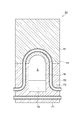
図3〜5に示すとおり、炉底部構造50の中央部に貫通孔5が設けられている。溶融炉部4内の圧力よりも保圧室6内の圧力を高く設定したときには、溶融炉部4の酸化性ガスを含むバーナ排ガスが貫通孔5を通じて炉外から炉内に流入するとともに炉内から炉外に溶融物Mが排出される。炉底部構造50は、貫通孔5の上側内周面5aを構成するアルミナ系耐火物ブロックB1と、下側内周面5bを構成する炭化珪素質耐火物ブロックB2と、貫通孔5の周りに埋設された複数の管路P1〜P4とを備える。
As shown in FIGS. 3 to 5, the through
アルミナ系耐火物ブロックB1は、溶融炉部4の炉底部の側壁4wの外面F1から内面F2にかけて貫通孔5の上側内周面5aを構成している。アルミナ系耐火物ブロックB1は高温(例えば1500〜1800℃)の酸化性ガスに対して耐性を有するものが好ましく、溶融物Mの飛沫が付着する可能性もあるため、溶融物Mに対してもある程度の耐性を有するものが好ましい。アルミナ系耐火物ブロックB1の具体例としては、高アルミナ質耐火キャスタブル(アルミナ含有率:90質量%以上)などが挙げられる。アルミナ系耐火物ブロックB1は、過冷却によって溶融物が固化することを抑制する観点から、1000℃における熱伝導率が好ましくは1.5〜2.5W/m・Kであり、より好ましくは1.5〜2.0W/m・Kである。
The alumina-based refractory block B1 constitutes the upper inner
炭化珪素質耐火物ブロックB2は、溶融炉部4の炉底部の側壁4wの内面F2から外面F1にかけて貫通孔5の下側内周面5bを構成している。下側内周面5bは、溶融物Mが炉外に向けて流れ落ちるように傾斜している底面5dを有する。炭化珪素質耐火物ブロックB2は高温(例えば1600℃程度)の溶融物Mに対して耐性を有するものが好ましく、酸化性ガスを含むバーナ排ガスに曝される可能性もあるため、酸化性ガスに対してもある程度の耐性を有するものが好ましい。炭化珪素質耐火物ブロックB2の具体例としては、SiC耐火キャスタブル(SiC含有量:67〜95質量%)などが挙げられる。炭化珪素質耐火物ブロックB2は、1000℃における熱伝導率が好ましくは10〜15W/m・Kであり、より好ましくは12〜15W/m・Kである。炭化珪素質耐火物ブロックB2の熱伝導率が上記範囲であると、管路P1による冷却効果と溶融物Mの熱とをバランスさせることによって炭化珪素質耐火物ブロックB2の残厚を十分に確保しやすい。
The silicon carbide refractory block B2 constitutes the lower inner
図3に示すように、貫通孔5の上側内周面5aは、アルミナ系耐火物ブロックB1に形成された溝であって外面F1に平行な断面の形状が略半円状である溝によって構成されている。他方、貫通孔5の下側内周面5bは、炭化珪素質耐火物ブロックB2に形成された溝であって外面F1に平行な断面の形状が縦長の略長方形である溝によって構成されている。この縦長の略長方形の溝は、溶融物出口をなす貫通孔5の外側開口において、縦長の略長方形の溝からなるスリット部5sを構成する。
As shown in FIG. 3, the upper inner
スリット部5sの開口幅は、未燃焼(炉内に装入前)のコークスCが通過しないサイズに設定されていることが好ましく、65〜130mm程度であればよい。かかる構成を採用することで、炉内に装入したコークスCが貫通孔5から排出されるのを抑制できる。貫通孔5の開口面積は使用するコークスCのサイズ、廃棄物ガス化溶融炉10の規模などに応じて設定すればよく、例えば50〜500cm2程度であればよい。
The opening width of the
本実施形態においては、溶融物出口を構成するスリット部5sの両側にスリット部5sに沿って縦方向に延びる一対の張り出し部5h,5hが設けられている。張り出し部5h,5hは、溶融物出口の近傍に溶融物Mが付着し、それが徐々に堆積することによって溶融物出口が閉塞されることを防止するためのものである。
In the present embodiment, a pair of projecting
図3に示すように、張り出し部5hは貫通孔5の下側内周面5bから炉外の方向に連続して延びている第1の面F5aと、第1の面F5aとともに鋭角部5jを構成する第2の面F5bとを有する。スリット部5sの両側に鋭角部5jを有する張り出し部5hをそれぞれ設けることで、鋭角部5jを超えて溶融物Mがスリット部5sの左右方向に広がることを十分に抑制でき、これにより、溶融物出口の近傍における溶融物Mの付着を抑制することができる。鋭角部5jの角度は20〜60°(より好ましくは20〜45°)程度であればよい。
As shown in FIG. 3, the overhanging
溶融物Mの付着抑制効果をより高めるため、張り出し部5hの第2の面F5b上及び外面F1に複数の突起部5pを設けてもよい。本実施形態においては、図3に示すように、第2の面F5b上に横方向に延びる複数段(五段)の突起部5pを設けた場合を例示したが、突起部の態様はこれに限定されるものではない。第2の面F5bに溶融物が付着するのを防止するには、第2の面F5bが平坦面ではなく凹凸を有していればよく、例えば、第2の面F5bに複数の突起部を設ける代わりに複数の凹部を設けてもよい。
In order to further enhance the adhesion suppressing effect of the melt M, a plurality of
管路P1〜P4は、冷却用流体(例えば水、空気)を流すためのものである。図4,5に示すように、管路P1,P2は、炉底部構造50のうち溶融物出口側に埋設されている。管路P3,P4は、炉底部構造50のうち溶融炉部4側に埋設されている。なお、管路の本数は五本に限定されるものではない。炉底部構造50の溶融物出口側は、炉底部構造50の溶融炉部4側に対して分離可能に構成されていてもよい。かかる構成により、炉底部構造50の溶融物出口側のみを交換することができる。
The pipes P1 to P4 are for flowing a cooling fluid (for example, water or air). As shown in FIGS. 4 and 5, the pipes P <b> 1 and P <b> 2 are embedded in the melt outlet side of the
管路P1は、底面5dの先端側(炉外側)の位置において底面5dに沿うように炭化珪素質耐火物ブロックB2に埋設されており且つ底面5d上の溶融物Mの流れ方向と交差する方向に延在している。底面5dの先端側の位置に管路P1を埋設することで、溶融物Mの流れによって炭化珪素質耐火物ブロックB2の先端側が浸食されることをより一層確実に抑制できる。
Pipe line P1 is embedded in silicon carbide refractory block B2 along
管路P2は、図5に示すように、管路P1の上方に位置し且つ貫通孔5の内周面(底面5dを除く。)に沿うように埋設されている。すなわち、管路P2は、管路P1と同様、まず、炭化珪素質耐火物ブロックB2内において横方向に延び、貫通孔5の近傍で上方に曲がって貫通孔5の側面に沿って上方に延びている。そして、アルミナ系耐火物ブロックB1内おいて貫通孔5の上側内周面5aに沿って半円を描くように延び、炭化珪素質耐火物ブロックB2内において貫通孔5の側面に沿って下方に延びている。そして、管路P1の手前で横方向に曲がっている。
As shown in FIG. 5, the pipe line P <b> 2 is embedded above the pipe line P <b> 1 and along the inner peripheral surface (excluding the
管路P3,P4は、炉底部構造50のうち溶融炉部4側に埋設されており、溶融炉部4側の位置において図5に示す管路P2と同様、貫通孔5の内周面(底面5dを除く。)に沿うように埋設されている。
The pipes P3 and P4 are embedded in the
管路P1から貫通孔5の底面5dまでの距離(炭化珪素質耐火物ブロックB2の施工時の初期厚さ)は好ましくは1〜100mmであり、より好ましくは30〜60mmである。管路P2、管路P3及び管路P4から貫通孔5の上側内周面5aまでの距離(アルミナ系耐火物ブロックB1の施工時の初期厚さ)は好ましくは1〜100mmであり、より好ましくは30〜60mmである。
The distance from the pipe line P1 to the
管路P1〜P4は、金属管(例えば銅管)と、金属管の表面に形成されたニッケルクロム合金層からなる肉盛部とを有することが好ましい。かかる構成の管路を採用することで、アルミナ系耐火物ブロックB1又は炭化珪素質耐火物ブロックB2の損耗によって管路が露出しても一定の期間にわたって耐久性を保持することができる。ニッケルクロム合金層の厚さは1〜10mm(より好ましくは3〜5mm)程度とすればよい。 The pipes P1 to P4 preferably have a metal pipe (for example, a copper pipe) and a built-up portion made of a nickel-chrome alloy layer formed on the surface of the metal pipe. By adopting such a pipeline, durability can be maintained for a certain period even if the pipeline is exposed due to wear of the alumina-based refractory block B1 or the silicon carbide refractory block B2. The thickness of the nickel chromium alloy layer may be about 1 to 10 mm (more preferably 3 to 5 mm).
本実施形態に係る炉底部構造50は、優れた耐久性を有し且つ貫通孔5を定常的に開放した状態で廃棄物ガス化溶融炉10を十分に高い熱効率で運転するのに有用である。
The
<廃棄物ガス化溶融炉の運転方法>
廃棄物ガス化溶融炉10の運転方法について説明する。処理すべき廃棄物を廃棄物装入口11からシャフト部1に装入する。廃棄物の種類は、特に限定されることはなく、一般廃棄物及び産業廃棄物のいずれであってもよい。シュレッダーダスト(ASR)、掘り起こしごみ、焼却灰などの単体又は混合物、あるいはこれらと可燃性ごみの混合物なども処理することが可能である。廃棄物によってシャフト部1内に廃棄物充填層100が形成される。廃棄物装入口11から乾留された廃棄物やチャーを廃棄物とともに投入してもよい。
<Operation method of waste gasification melting furnace>
An operation method of the waste
シャフト部1内においては、炭化火格子部3及び溶融炉部4から吹き込まれた空気や炉内で発生したガスが廃棄物充填層100を通過するときの熱交換によって、廃棄物の乾燥及び熱分解が進行する。廃棄物の乾燥及び熱分解には廃棄物自身が発する熱も利用される。廃棄物は、シャフト部1内を徐々に降下し、供給炭化火格子3A上に到達し、供給炭化火格子3Aで更に熱分解され、その後、乾留炭化火格子3Bへと送られる。廃棄物は、乾留炭化火格子3Bで更に熱分解されて炭化が進行し、上部側開口部46から落下して溶融炉部4に供給される。
In the
連通部2から炭化された廃棄物が溶融炉部4に供給される。炭化された廃棄物によって溶融炉部4内に充填層101が形成される。溶融炉部4内には副資材装入口41からコークスCと、必要に応じて塩基度調整剤(例えば石灰石)とを装入する。また、羽口42a,42b,42c,42dから酸素富化空気を吹き込むことによってコークスC及び廃棄物の固定炭素を燃焼させる。これにより炉底に高温のコークスベッドBcが形成され、その熱で廃棄物に含まれる灰分や不燃成分を溶融する。一方、炉内ガス排出口12から排出された高温ガスは、ボイラー等の装置で廃熱を回収した後、無害化処理をして放出する。なお、溶融炉部4内にコークスベッドBcを形成することで、溶融炉部4内を高温状態(例えば1700℃超)に安定的に維持できる。ここでは溶融炉部4内にコークスベッドBcを形成する場合を例示したが、溶融炉部4にコークスベッドBcが形成されなくてもよい。
Waste carbonized from the
操業時における溶融炉部4内の廃棄物の充填高さは、羽口42a,42b,42c,42dより上方向+0.5m〜炭化火格子部3の最下端部までの範囲内に維持することが好ましい。この範囲内に維持することによって、充填層101の層厚が薄くなることに起因する炉底からの酸素リークを抑制することができる。更に、充填し過ぎに起因する炭化火格子部3の熱分解効率低下や溶融炉部4内における物流停滞の発生を抑制できる。
The filling height of the waste in the
溶融炉部4内の廃棄物の充填高さの制御は、炭化火格子部3が溶融炉部4に廃棄物を供給する速度を調節することによって行うことができる。例えば、溶融炉部4に充填層101の高さを検知するためのセンサー(不図示)を配置し、センサーが検知する充填層101の高さに基づいて炭化火格子部3の供給速度を制御してもよい。あるいは、例えばオペレーターが充填高さを監視し、監視結果に基づいて供給速度を制御してもよい。
The filling height of the waste in the
供給炭化火格子3Aの供給速度(V1)と乾留炭化火格子3Bの供給速度(V2)は、相対的に異なるように設定してもよく、あるいは同じに設定してもよい。供給速度を相対的に異なるように設定する場合、乾留炭化火格子3Bの供給速度(V2)が供給炭化火格子3Aの供給速度(V1)よりも大きくなるように設定することが好ましい。更に、乾留炭化火格子3Bの供給速度(V2)を一定にして、供給炭化火格子3Aの供給速度(V1)を可変制御することがより好ましい。供給速度V2を供給速度V1よりも大きくすることで、供給炭化火格子3Aから送られてきた廃棄物が乾留炭化火格子3B上において比較的薄い層をなすように広げることができる。これにより、廃棄物の層の全体に乾留炭化火格子3Bからの熱を加えることができ、廃棄物全体の炭化状態を十分に良好にできる。
The supply rate (V1) of the
廃棄物の装入は、廃棄物装入口11のみからではなく、例えば副資材装入口41から装入してもよい。例えば、水分量が多い廃棄物は廃棄物装入口11から装入して、シャフト部1及び炭化火格子部3における処理を経た後に溶融炉部4に供給することが好ましい。他方、灰分量が多くて水分が少ない廃棄物は、副資材装入口41から装入することで、シャフト部1及び炭化火格子部3における乾燥及び熱分解の負荷を軽減できる。水分量が多い廃棄物の一例として汚泥が挙げられ、灰分量が多い廃棄物の一例として焼却灰が挙げられる。なお、廃棄物の装入口は廃棄物装入口11及び副資材装入口41以外の場所にも設けてもよい。廃棄物の性状に基づいて廃棄物を炉内に装入する位置を適宜変えることで、結果として炉全体の負荷を軽減できる。
For example, the waste material may be charged not only from the waste material inlet 11 but also from the auxiliary
次に、貫通孔5を定常的に開放した状態で廃棄物ガス化溶融炉10を運転することに関し、本実施形態に係る運転方法について具体的に説明する。この運転方法によれば、廃棄物ガス化溶融炉10を十分に高い熱効率で運転できる。本実施形態に係る運転方法は以下の工程を含む。
溶融炉部4内の圧力よりも保圧室6内の圧力を高く維持することにより、貫通孔5を通じて保圧室6内のガスを溶融炉部4内に流入させること。
溶融炉部4内の溶融物Mを貫通孔5から保圧室6側に排出すること。
貫通孔5から排出される溶融物Mに対してバーナ7によって熱を加えること。
炉底部構造50が著しく損耗したり溶融物出口が閉塞したりした場合に炉底部構造50を新たな炉底部構造50に交換すること。
Next, regarding the operation of the waste
The gas in the pressure holding chamber 6 is caused to flow into the
The molten material M in the
Heat is applied to the melt M discharged from the through
Replacing the
この運転方法によれば、貫通孔5から排出される溶融物Mをバーナ7の火炎で加熱することができる。これにより溶融物Mの粘性上昇を抑制でき、貫通孔5の閉塞を抑制できる。更に、バーナ7から発生する燃焼ガスによって保圧室6内の圧力(例えば1.5〜2.5kPa(ゲージ圧))を溶融炉部4内の圧力(例えば1.0〜2.0kPa(ゲージ圧))よりも高い状態にすることができる。この差圧は好ましくは0.5〜2.0kPaである。この差圧により貫通孔5を通じて燃焼ガスが溶融炉部4に流入する。すなわち、保圧室6内の圧力を溶融炉部4内の圧力よりも高くすることで、高温の炉内ガスが貫通孔5を通じて炉外に排出されるのを防止するとともに、十分に高い温度の燃焼ガスを保圧室6から溶融炉部4へと貫通孔5を通じて流入させることができる。その結果、溶融炉部4内の温度(炉内温度)の低下を抑えることができ、炉内に導入すべき燃料の増加を十分に抑制できる。なお、貫通孔5を通過する燃焼ガスの温度が1200℃以上(より好ましくは1300℃程度)であれば、貫通孔5周辺で溶融物Mが固化することを十分に抑制できる。溶融物Mに含まれるスラグの融点はその組成に依存するが1175℃程度である。
According to this operation method, the melt M discharged from the through
貫通孔5における溶融物Mと燃焼ガスの流れに着目すると、貫通孔5において溶融物Mとガスは対向流となっている。貫通孔5から溶融物Mを安定的に排出するには、貫通孔5内において溶融物Mの流れが燃焼ガスの流れと十分に分離していることが好ましい。つまり、貫通孔5内の流体の流れを対向気液二相流とみなした場合、溶融物Mが分離流(層状流又は波状流)を形成していることが好ましい。かかる観点から、貫通孔5の開口面積、コークスCのサイズ及び保圧室6から溶融炉部4に流入するガス流量などを設定すればよい。例えば、貫通孔5を通過する燃焼ガスの流速は好ましくは0〜20Bm/sであり、より好ましくは3〜10Bm/sである。なお、流速の単位「Bm/s」はその場の温度及び圧力条件下での流速を意味する。
When attention is paid to the flow of the melt M and the combustion gas in the through
新たな炉底部構造50への交換は、損耗によって管路が露出したり、溶融物出口が閉塞したりした場合に実施すればよい。これらの現象が認められない場合であっても、所定の期間が経過したら定期的に交換するようにしてもよい。
The replacement to the new
以上、本発明の実施形態について詳細に説明したが、形式や細部についての種々の置換、変形、変更等が、特許請求の範囲の記載により規定されるような本発明の精神及び範囲から逸脱することなく行われることが可能であることは、当該技術分野における通常の知識を有する者には明らかである。従って、本発明の範囲は、上記実施形態及び添付図面に限定されるものではなく、特許請求の範囲の記載及びこれと均等なものに基づいて定められるべきである。 As mentioned above, although embodiment of this invention was described in detail, various substitution, a deformation | transformation, a change, etc. about a form and detail deviate from the mind and range of this invention as prescribed | regulated by description of a claim. It is clear to those having ordinary knowledge in the art that it can be done without any problems. Therefore, the scope of the present invention should not be limited to the above-described embodiment and the accompanying drawings, but should be determined based on the description of the claims and equivalents thereof.
例えば、上記実施形態においては、溶融物出口の両側に一対の張り出し部5h,5hを設ける場合を例示したが、溶融物Mの性状等によっては張り出し部5h,5hを設けなくてもよい。また、上記実施形態においては、縦長の略長方形の溝によって構成される溶融物出口を例示したが、溶融物出口の形状は必ずしも略長方形でなくてもよく、例えば縦長の楕円や多角形状などであってもよい。
For example, in the above-described embodiment, the case where the pair of
1…シャフト部、2…連通部、3…炭化火格子部、4…溶融炉部、4w…側壁、5…貫通孔、5a…上側内周面、5b…下側内周面、5d…底面、5h…張り出し部、5j…鋭角部、5p…突起部、5s…スリット部、6…保圧室、7…バーナ、10…廃棄物ガス化溶融炉(低炭素型シャフト炉)、11…廃棄物装入口、12…炉内ガス排出口、50…炉底部構造、M…溶融物、B1…アルミナ系耐火物ブロック、B2…炭化珪素質耐火物ブロック、F5a…第1の面、F5b…第2の面、P1〜P4…管路。
DESCRIPTION OF
Claims (9)
前記貫通孔の内周面のうち、前記バーナ排ガスと接する上側内周面を前記側壁の外側から内側にかけて構成するアルミナ系耐火物ブロックと、
前記貫通孔の内周面のうち、前記溶融物と接する底面を含む下側内周面を前記側壁の内側から外側にかけて構成する炭化珪素質耐火物ブロックと、
前記貫通孔の周りに埋設された、冷却用流体を流すための少なくとも一つの管路と、
を備える炉底部構造。 Penetration through which the burner exhaust gas containing oxidizing gas flows from the outside of the furnace into the furnace and discharges the melt from the inside of the furnace to the outside of the furnace through the thickness of the bottom wall of the low carbon shaft furnace. A furnace bottom structure having holes,
Of the inner peripheral surface of the through hole, an alumina-based refractory block that configures an upper inner peripheral surface in contact with the burner exhaust gas from the outside to the inside of the side wall;
Of the inner peripheral surface of the through hole, a silicon carbide refractory block that configures a lower inner peripheral surface including a bottom surface in contact with the melt from the inner side to the outer side of the side wall,
At least one conduit for flowing a cooling fluid embedded around the through hole;
A furnace bottom structure comprising:
前記スリット部の両側に前記スリット部に沿って縦方向に延びる一対の張り出し部が設けられており、
前記張り出し部は、前記貫通孔の前記下側内周面から炉外の方向に連続して延びている第1の面と、前記第1の面とともに鋭角部を構成する第2の面とを有する、請求項7に記載の炉底部構造。 The outer opening of the through-hole constituting the outlet of the melt has a slit portion constituted by the vertically long, substantially rectangular groove,
A pair of overhang portions extending in the vertical direction along the slit portion are provided on both sides of the slit portion,
The projecting portion includes a first surface continuously extending in a direction outside the furnace from the lower inner peripheral surface of the through hole, and a second surface constituting an acute angle portion together with the first surface. The furnace bottom structure according to claim 7, comprising:
Priority Applications (1)
| Application Number | Priority Date | Filing Date | Title |
|---|---|---|---|
| JP2016017985A JP6643116B2 (en) | 2016-02-02 | 2016-02-02 | Furnace bottom structure of low carbon shaft furnace |
Applications Claiming Priority (1)
| Application Number | Priority Date | Filing Date | Title |
|---|---|---|---|
| JP2016017985A JP6643116B2 (en) | 2016-02-02 | 2016-02-02 | Furnace bottom structure of low carbon shaft furnace |
Publications (2)
| Publication Number | Publication Date |
|---|---|
| JP2017138032A true JP2017138032A (en) | 2017-08-10 |
| JP6643116B2 JP6643116B2 (en) | 2020-02-12 |
Family
ID=59566354
Family Applications (1)
| Application Number | Title | Priority Date | Filing Date |
|---|---|---|---|
| JP2016017985A Active JP6643116B2 (en) | 2016-02-02 | 2016-02-02 | Furnace bottom structure of low carbon shaft furnace |
Country Status (1)
| Country | Link |
|---|---|
| JP (1) | JP6643116B2 (en) |
Cited By (1)
| Publication number | Priority date | Publication date | Assignee | Title |
|---|---|---|---|---|
| JP2020098088A (en) * | 2018-12-13 | 2020-06-25 | 日鉄エンジニアリング株式会社 | Cooling structure of tapping port section of melting furnace and manufacturing method of metallic plate block used therefor |
Citations (13)
| Publication number | Priority date | Publication date | Assignee | Title |
|---|---|---|---|---|
| JPS4932174B1 (en) * | 1969-11-27 | 1974-08-28 | ||
| JPH05106826A (en) * | 1991-10-14 | 1993-04-27 | Nippon Steel Corp | Waste melting furnace |
| JPH08121739A (en) * | 1994-10-27 | 1996-05-17 | Takuma Co Ltd | Electric melting furnace |
| JP2000283447A (en) * | 1999-03-31 | 2000-10-13 | Nkk Corp | Slag outlet of melting furnace |
| JP2000283425A (en) * | 1999-03-31 | 2000-10-13 | Nkk Corp | Outlet |
| JP2001164227A (en) * | 1999-11-29 | 2001-06-19 | Vantico Ag | Adhesive composition |
| JP2003065683A (en) * | 2001-06-11 | 2003-03-05 | Nkk Corp | Slag outlet, waste gasification / melting furnace equipped with the slag outlet, and method of replacing the slag outlet |
| JP2003294215A (en) * | 2002-04-01 | 2003-10-15 | Fuji Heavy Ind Ltd | Outlet structure of horizontal rotary furnace |
| JP2008249317A (en) * | 2007-03-08 | 2008-10-16 | Nippon Steel Engineering Co Ltd | Waste bottom furnace bottom structure |
| JP2009008313A (en) * | 2007-06-27 | 2009-01-15 | Nippon Steel Engineering Co Ltd | Continuous hot water supply system for waste melting furnace |
| JP2010043840A (en) * | 2008-07-15 | 2010-02-25 | Nippon Steel Engineering Co Ltd | Method and apparatus for melting waste |
| KR101288387B1 (en) * | 2012-07-30 | 2013-07-22 | 지에스플라텍 주식회사 | Tapping device and gasification melting furnace comprinsing the same |
| JP2017032189A (en) * | 2015-07-30 | 2017-02-09 | 新日鉄住金エンジニアリング株式会社 | Operation method of waste gasification melting furnace |
-
2016
- 2016-02-02 JP JP2016017985A patent/JP6643116B2/en active Active
Patent Citations (13)
| Publication number | Priority date | Publication date | Assignee | Title |
|---|---|---|---|---|
| JPS4932174B1 (en) * | 1969-11-27 | 1974-08-28 | ||
| JPH05106826A (en) * | 1991-10-14 | 1993-04-27 | Nippon Steel Corp | Waste melting furnace |
| JPH08121739A (en) * | 1994-10-27 | 1996-05-17 | Takuma Co Ltd | Electric melting furnace |
| JP2000283447A (en) * | 1999-03-31 | 2000-10-13 | Nkk Corp | Slag outlet of melting furnace |
| JP2000283425A (en) * | 1999-03-31 | 2000-10-13 | Nkk Corp | Outlet |
| JP2001164227A (en) * | 1999-11-29 | 2001-06-19 | Vantico Ag | Adhesive composition |
| JP2003065683A (en) * | 2001-06-11 | 2003-03-05 | Nkk Corp | Slag outlet, waste gasification / melting furnace equipped with the slag outlet, and method of replacing the slag outlet |
| JP2003294215A (en) * | 2002-04-01 | 2003-10-15 | Fuji Heavy Ind Ltd | Outlet structure of horizontal rotary furnace |
| JP2008249317A (en) * | 2007-03-08 | 2008-10-16 | Nippon Steel Engineering Co Ltd | Waste bottom furnace bottom structure |
| JP2009008313A (en) * | 2007-06-27 | 2009-01-15 | Nippon Steel Engineering Co Ltd | Continuous hot water supply system for waste melting furnace |
| JP2010043840A (en) * | 2008-07-15 | 2010-02-25 | Nippon Steel Engineering Co Ltd | Method and apparatus for melting waste |
| KR101288387B1 (en) * | 2012-07-30 | 2013-07-22 | 지에스플라텍 주식회사 | Tapping device and gasification melting furnace comprinsing the same |
| JP2017032189A (en) * | 2015-07-30 | 2017-02-09 | 新日鉄住金エンジニアリング株式会社 | Operation method of waste gasification melting furnace |
Cited By (2)
| Publication number | Priority date | Publication date | Assignee | Title |
|---|---|---|---|---|
| JP2020098088A (en) * | 2018-12-13 | 2020-06-25 | 日鉄エンジニアリング株式会社 | Cooling structure of tapping port section of melting furnace and manufacturing method of metallic plate block used therefor |
| JP7294830B2 (en) | 2018-12-13 | 2023-06-20 | 日鉄エンジニアリング株式会社 | A cooling structure for the outlet of a melting furnace and a method for manufacturing a metal plate block used in the cooling structure. |
Also Published As
| Publication number | Publication date |
|---|---|
| JP6643116B2 (en) | 2020-02-12 |
Similar Documents
| Publication | Publication Date | Title |
|---|---|---|
| WO2013128524A1 (en) | Waste gasification and melting furnace | |
| JP6611626B2 (en) | Operation method of waste gasification melting furnace | |
| JP2008201852A (en) | Cyclone-type solid-gas separator and carbonizing apparatus equipped with the solid-gas separator | |
| US7384263B2 (en) | Process for burning lumps of material with lean gas | |
| CN102056850B (en) | Glass melting furnace | |
| JP6643116B2 (en) | Furnace bottom structure of low carbon shaft furnace | |
| JP5855785B1 (en) | Operation method of waste gasification melting furnace | |
| JP5855786B1 (en) | Operation method of waste gasification melting furnace | |
| JP4685671B2 (en) | Waste melting processing equipment | |
| JP5909583B1 (en) | Operation method of waste gasification melting furnace | |
| JP5909584B1 (en) | Operation method of waste gasification melting furnace | |
| EA027331B1 (en) | Heating apparatus and gas distributor for use therein | |
| JP5855784B1 (en) | Wet wall structure | |
| US6571721B1 (en) | Ash melting apparatus | |
| JPH0346723B2 (en) | ||
| CN219735326U (en) | Wear-resisting structure of water-cooled wall of garbage incinerator | |
| JPS6023714A (en) | Fusing method of industrial waste | |
| JP2019066110A (en) | Melting treatment equipment of incineration ash | |
| JP2004169999A (en) | Incineration and melting furnace | |
| JP5886144B2 (en) | Waste treatment equipment | |
| US896937A (en) | Furnace-port-cooling means. | |
| JP2004125203A (en) | Ash melting device and operation method | |
| JP2000283447A (en) | Slag outlet of melting furnace | |
| JP2007085562A (en) | Shaft furnace type gasification melting furnace | |
| JPH0372889B2 (en) |
Legal Events
| Date | Code | Title | Description |
|---|---|---|---|
| A621 | Written request for application examination |
Free format text: JAPANESE INTERMEDIATE CODE: A621 Effective date: 20181002 |
|
| A977 | Report on retrieval |
Free format text: JAPANESE INTERMEDIATE CODE: A971007 Effective date: 20190619 |
|
| A131 | Notification of reasons for refusal |
Free format text: JAPANESE INTERMEDIATE CODE: A131 Effective date: 20190625 |
|
| TRDD | Decision of grant or rejection written | ||
| A01 | Written decision to grant a patent or to grant a registration (utility model) |
Free format text: JAPANESE INTERMEDIATE CODE: A01 Effective date: 20191210 |
|
| A61 | First payment of annual fees (during grant procedure) |
Free format text: JAPANESE INTERMEDIATE CODE: A61 Effective date: 20200106 |
|
| R150 | Certificate of patent or registration of utility model |
Ref document number: 6643116 Country of ref document: JP Free format text: JAPANESE INTERMEDIATE CODE: R150 |
|
| S111 | Request for change of ownership or part of ownership |
Free format text: JAPANESE INTERMEDIATE CODE: R313115 |
|
| R350 | Written notification of registration of transfer |
Free format text: JAPANESE INTERMEDIATE CODE: R350 |
|
| R250 | Receipt of annual fees |
Free format text: JAPANESE INTERMEDIATE CODE: R250 |
|
| R250 | Receipt of annual fees |
Free format text: JAPANESE INTERMEDIATE CODE: R250 |
|
| R250 | Receipt of annual fees |
Free format text: JAPANESE INTERMEDIATE CODE: R250 |
|
| R250 | Receipt of annual fees |
Free format text: JAPANESE INTERMEDIATE CODE: R250 |