JP2017138068A - 航空部品及び航空用ガスタービンエンジン - Google Patents
航空部品及び航空用ガスタービンエンジン Download PDFInfo
- Publication number
- JP2017138068A JP2017138068A JP2016019997A JP2016019997A JP2017138068A JP 2017138068 A JP2017138068 A JP 2017138068A JP 2016019997 A JP2016019997 A JP 2016019997A JP 2016019997 A JP2016019997 A JP 2016019997A JP 2017138068 A JP2017138068 A JP 2017138068A
- Authority
- JP
- Japan
- Prior art keywords
- boss
- aviation
- flange
- annular
- axial direction
- Prior art date
- Legal status (The legal status is an assumption and is not a legal conclusion. Google has not performed a legal analysis and makes no representation as to the accuracy of the status listed.)
- Granted
Links
Images


Classifications
-
- F—MECHANICAL ENGINEERING; LIGHTING; HEATING; WEAPONS; BLASTING
- F23—COMBUSTION APPARATUS; COMBUSTION PROCESSES
- F23R—GENERATING COMBUSTION PRODUCTS OF HIGH PRESSURE OR HIGH VELOCITY, e.g. GAS-TURBINE COMBUSTION CHAMBERS
- F23R3/00—Continuous combustion chambers using liquid or gaseous fuel
- F23R3/002—Wall structures
-
- F—MECHANICAL ENGINEERING; LIGHTING; HEATING; WEAPONS; BLASTING
- F23—COMBUSTION APPARATUS; COMBUSTION PROCESSES
- F23R—GENERATING COMBUSTION PRODUCTS OF HIGH PRESSURE OR HIGH VELOCITY, e.g. GAS-TURBINE COMBUSTION CHAMBERS
- F23R3/00—Continuous combustion chambers using liquid or gaseous fuel
- F23R3/28—Continuous combustion chambers using liquid or gaseous fuel characterised by the fuel supply
-
- B—PERFORMING OPERATIONS; TRANSPORTING
- B64—AIRCRAFT; AVIATION; COSMONAUTICS
- B64D—EQUIPMENT FOR FITTING IN OR TO AIRCRAFT; FLIGHT SUITS; PARACHUTES; ARRANGEMENT OR MOUNTING OF POWER PLANTS OR PROPULSION TRANSMISSIONS IN AIRCRAFT
- B64D27/00—Arrangement or mounting of power plants in aircraft; Aircraft characterised by the type or position of power plants
- B64D27/02—Aircraft characterised by the type or position of power plants
- B64D27/10—Aircraft characterised by the type or position of power plants of gas-turbine type
-
- F—MECHANICAL ENGINEERING; LIGHTING; HEATING; WEAPONS; BLASTING
- F23—COMBUSTION APPARATUS; COMBUSTION PROCESSES
- F23R—GENERATING COMBUSTION PRODUCTS OF HIGH PRESSURE OR HIGH VELOCITY, e.g. GAS-TURBINE COMBUSTION CHAMBERS
- F23R3/00—Continuous combustion chambers using liquid or gaseous fuel
- F23R3/28—Continuous combustion chambers using liquid or gaseous fuel characterised by the fuel supply
- F23R3/283—Attaching or cooling of fuel injecting means including supports for fuel injectors, stems, or lances
-
- F—MECHANICAL ENGINEERING; LIGHTING; HEATING; WEAPONS; BLASTING
- F23—COMBUSTION APPARATUS; COMBUSTION PROCESSES
- F23R—GENERATING COMBUSTION PRODUCTS OF HIGH PRESSURE OR HIGH VELOCITY, e.g. GAS-TURBINE COMBUSTION CHAMBERS
- F23R3/00—Continuous combustion chambers using liquid or gaseous fuel
- F23R3/42—Continuous combustion chambers using liquid or gaseous fuel characterised by the arrangement or form of the flame tubes or combustion chambers
-
- F—MECHANICAL ENGINEERING; LIGHTING; HEATING; WEAPONS; BLASTING
- F23—COMBUSTION APPARATUS; COMBUSTION PROCESSES
- F23R—GENERATING COMBUSTION PRODUCTS OF HIGH PRESSURE OR HIGH VELOCITY, e.g. GAS-TURBINE COMBUSTION CHAMBERS
- F23R2900/00—Special features of, or arrangements for continuous combustion chambers; Combustion processes therefor
- F23R2900/00005—Preventing fatigue failures or reducing mechanical stress in gas turbine components
Landscapes
- Engineering & Computer Science (AREA)
- Chemical & Material Sciences (AREA)
- Combustion & Propulsion (AREA)
- Mechanical Engineering (AREA)
- General Engineering & Computer Science (AREA)
- Aviation & Aerospace Engineering (AREA)
- Structures Of Non-Positive Displacement Pumps (AREA)
- Turbine Rotor Nozzle Sealing (AREA)
Abstract
【解決手段】航空用ガスタービンエンジンに用いられる航空部品1において、外周面を有する円環部5と、円環部5の軸方向の一方の端部に形成されるフランジ部6と、円環部5の外周面から径方向に突出するボス部7と、を備え、円環部5の軸方向に沿って切った断面において、フランジ部6とボス部7との間における円環部5の外周面の形状は、フランジ部6からボス部7に向かって板厚が厚くなるテーパ形状に形成されたテーパ部15となっている。
【選択図】図2
Description
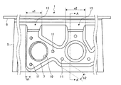
本実施形態に係る航空部品は、航空用ガスタービンエンジンに用いられるものであり、例えば、燃焼器のケーシングを構成する部品となっている。ここで、図1は、本実施形態に係る航空部品を示す図である。図2は、本実施形態に係る航空部品を軸方向に沿って切ったときの断面図である。図3及び図4は、本実施形態に係る航空部品と従来の航空部品との熱応力を比較した一例の説明図である。以下の説明では、航空部品として、燃焼器のケーシングに適用する場合について説明するが、特に限定されず、いずれの航空部品に適用してもよい。
5 円環部
6 フランジ部
7 ボス部
10 貫通孔
11 ボルト孔
15 テーパ部
Claims (6)
- 航空用ガスタービンエンジンに用いられる航空部品において、
外周面を有する円環部と、
前記円環部の軸方向の一方の端部に形成されるフランジ部と、
前記円環部の外周面から径方向に突出するボス部と、を備え、
前記円環部の軸方向に沿って切った断面において、前記フランジ部と前記ボス部との間における前記円環部の前記外周面の形状は、前記フランジ部から前記ボス部に向かって板厚が厚くなるテーパ形状に形成されたテーパ部となっていることを特徴とする航空部品。 - 前記円環部の軸方向における前記フランジ部と前記ボス部との間の距離をdとし、
前記円環部の軸方向における前記テーパ部の長さをd’とすると、
前記テーパ部の長さd’は、0.5d≦d’ ≦dの範囲となっていることを特徴とする請求項1に記載の航空部品。 - 前記円環部の軸方向における前記フランジ部と前記ボス部との間の距離をdとし、
前記円環部の軸方向に対する前記テーパ部の傾斜角度をθとし、
前記円環部において最薄となる最薄部の板厚をtとし、
前記ボス部における板厚をhとすると、
前記傾斜角度θは、0.3(h−t)/d≦θ≦(h−t)/dの範囲となっていることを特徴とする請求項1または2に記載の航空部品。 - 前記フランジ部は、前記円環部の周方向に延在して形成され、
前記ボス部は、前記フランジ部と対向する部位が、前記フランジ部と平行に形成されていることを特徴とする請求項1から3のいずれか1項に記載の航空部品。 - 前記フランジ部と平行となる前記ボス部の幅をaとし、
前記ボス部に貫通形成されるボルト孔を中心とする前記ボス部の周縁の曲率半径をbとすると、
前記ボス部の幅aは、b<a<3bの範囲となっていることを特徴とする請求項1から4のいずれか1項に記載の航空部品。 - 請求項1から5のいずれか1項に記載された航空部品を用いたことを特徴とする航空用ガスタービンエンジン。
Priority Applications (5)
| Application Number | Priority Date | Filing Date | Title |
|---|---|---|---|
| JP2016019997A JP6650774B2 (ja) | 2016-02-04 | 2016-02-04 | 航空部品及び航空用ガスタービンエンジン |
| EP16889327.9A EP3399235B8 (en) | 2016-02-04 | 2016-05-17 | Aircraft component and aircraft gas-turbine |
| US16/074,430 US11506385B2 (en) | 2016-02-04 | 2016-05-17 | Aircraft component and aircraft gas-turbine engine |
| CA3013294A CA3013294C (en) | 2016-02-04 | 2016-05-17 | Aircraft component and aircraft gas-turbine engine |
| PCT/JP2016/064603 WO2017134843A1 (ja) | 2016-02-04 | 2016-05-17 | 航空部品及び航空用ガスタービンエンジン |
Applications Claiming Priority (1)
| Application Number | Priority Date | Filing Date | Title |
|---|---|---|---|
| JP2016019997A JP6650774B2 (ja) | 2016-02-04 | 2016-02-04 | 航空部品及び航空用ガスタービンエンジン |
Publications (2)
| Publication Number | Publication Date |
|---|---|
| JP2017138068A true JP2017138068A (ja) | 2017-08-10 |
| JP6650774B2 JP6650774B2 (ja) | 2020-02-19 |
Family
ID=59499523
Family Applications (1)
| Application Number | Title | Priority Date | Filing Date |
|---|---|---|---|
| JP2016019997A Active JP6650774B2 (ja) | 2016-02-04 | 2016-02-04 | 航空部品及び航空用ガスタービンエンジン |
Country Status (5)
| Country | Link |
|---|---|
| US (1) | US11506385B2 (ja) |
| EP (1) | EP3399235B8 (ja) |
| JP (1) | JP6650774B2 (ja) |
| CA (1) | CA3013294C (ja) |
| WO (1) | WO2017134843A1 (ja) |
Families Citing this family (3)
| Publication number | Priority date | Publication date | Assignee | Title |
|---|---|---|---|---|
| JP6650774B2 (ja) * | 2016-02-04 | 2020-02-19 | 三菱重工航空エンジン株式会社 | 航空部品及び航空用ガスタービンエンジン |
| US10605169B2 (en) * | 2017-04-18 | 2020-03-31 | United Technologies Corporation | Combustor panel cooling arrangements |
| US12467387B1 (en) | 2024-08-29 | 2025-11-11 | Pratt & Whitney Canada Corp. | Turbine exhaust case structural flange |
Citations (7)
| Publication number | Priority date | Publication date | Assignee | Title |
|---|---|---|---|---|
| JPS4956018A (ja) * | 1972-06-01 | 1974-05-30 | ||
| JPS6414519A (en) * | 1987-06-18 | 1989-01-18 | Snecma | Combustion chamber casing for turbo jet engine containing air intake hole |
| US6314739B1 (en) * | 2000-01-13 | 2001-11-13 | General Electric Company | Brazeless combustor dome assembly |
| JP2008031871A (ja) * | 2006-07-26 | 2008-02-14 | Mitsubishi Heavy Ind Ltd | ストラット構造及びガスタービン |
| JP2008121685A (ja) * | 2006-11-15 | 2008-05-29 | General Electric Co <Ge> | 浸出間隙制御タービン |
| JP2013142533A (ja) * | 2012-01-09 | 2013-07-22 | General Electric Co <Ge> | 遅延希薄噴射システムトランジションピース |
| JP2013185588A (ja) * | 2012-03-05 | 2013-09-19 | General Electric Co <Ge> | ガスタービンフレーム補強レール |
Family Cites Families (6)
| Publication number | Priority date | Publication date | Assignee | Title |
|---|---|---|---|---|
| US6681577B2 (en) * | 2002-01-16 | 2004-01-27 | General Electric Company | Method and apparatus for relieving stress in a combustion case in a gas turbine engine |
| DE602004014154D1 (de) * | 2003-07-29 | 2008-07-10 | Pratt & Whitney Canada | Turbofan-Triebwerksgehäuse, Turbofantriebwerk und entsprechendes Verfahren |
| US20150240662A1 (en) * | 2012-09-28 | 2015-08-27 | United Technologies Corporation | Case assembly for a gas turbine engine |
| US9828880B2 (en) * | 2013-03-15 | 2017-11-28 | General Electric Company | Method and apparatus to improve heat transfer in turbine sections of gas turbines |
| US20160146052A1 (en) * | 2014-11-25 | 2016-05-26 | United Technologies Corporation | Forged cast forged outer case for a gas turbine engine |
| JP6650774B2 (ja) * | 2016-02-04 | 2020-02-19 | 三菱重工航空エンジン株式会社 | 航空部品及び航空用ガスタービンエンジン |
-
2016
- 2016-02-04 JP JP2016019997A patent/JP6650774B2/ja active Active
- 2016-05-17 EP EP16889327.9A patent/EP3399235B8/en active Active
- 2016-05-17 US US16/074,430 patent/US11506385B2/en active Active
- 2016-05-17 CA CA3013294A patent/CA3013294C/en active Active
- 2016-05-17 WO PCT/JP2016/064603 patent/WO2017134843A1/ja not_active Ceased
Patent Citations (7)
| Publication number | Priority date | Publication date | Assignee | Title |
|---|---|---|---|---|
| JPS4956018A (ja) * | 1972-06-01 | 1974-05-30 | ||
| JPS6414519A (en) * | 1987-06-18 | 1989-01-18 | Snecma | Combustion chamber casing for turbo jet engine containing air intake hole |
| US6314739B1 (en) * | 2000-01-13 | 2001-11-13 | General Electric Company | Brazeless combustor dome assembly |
| JP2008031871A (ja) * | 2006-07-26 | 2008-02-14 | Mitsubishi Heavy Ind Ltd | ストラット構造及びガスタービン |
| JP2008121685A (ja) * | 2006-11-15 | 2008-05-29 | General Electric Co <Ge> | 浸出間隙制御タービン |
| JP2013142533A (ja) * | 2012-01-09 | 2013-07-22 | General Electric Co <Ge> | 遅延希薄噴射システムトランジションピース |
| JP2013185588A (ja) * | 2012-03-05 | 2013-09-19 | General Electric Co <Ge> | ガスタービンフレーム補強レール |
Also Published As
| Publication number | Publication date |
|---|---|
| WO2017134843A1 (ja) | 2017-08-10 |
| EP3399235B8 (en) | 2020-08-26 |
| US11506385B2 (en) | 2022-11-22 |
| CA3013294A1 (en) | 2017-08-10 |
| JP6650774B2 (ja) | 2020-02-19 |
| EP3399235A1 (en) | 2018-11-07 |
| US20190032918A1 (en) | 2019-01-31 |
| CA3013294C (en) | 2020-06-09 |
| EP3399235B1 (en) | 2020-07-15 |
| EP3399235A4 (en) | 2018-11-21 |
Similar Documents
| Publication | Publication Date | Title |
|---|---|---|
| US9874101B2 (en) | Platform with curved edges | |
| US10731564B2 (en) | Transition structure | |
| EP3343002B1 (en) | Casing for gas turbine and gas turbine | |
| CA2897284C (en) | GAS TURBINE EXHAUST EJECTOR/MIXER | |
| US10012390B2 (en) | Combustion chamber of a gas turbine with bolted combustion chamber head | |
| JP2017138068A (ja) | 航空部品及び航空用ガスタービンエンジン | |
| JP2018525558A (ja) | 後付けファンブレードプラットフォームを備える航空ターボ機械の回転アセンブリ | |
| US10273904B2 (en) | Fairing for a mixer of a nozzle of a dual-flow turbomachine | |
| US11834957B2 (en) | Strut cover, exhaust casing, and gas turbine | |
| EP2980393B1 (en) | Gas turbine engine | |
| US7971439B2 (en) | Annular turbomachine combustion chamber | |
| US9879550B2 (en) | Outer shroud with gusset | |
| US10767484B2 (en) | Rotor disk comprising a variable thickness web | |
| US10920598B2 (en) | Rotor assembly cover plate | |
| US10294961B2 (en) | Cylindrical case | |
| US9097142B2 (en) | Alignment of static parts in a gas turbine engine | |
| JP5881877B2 (ja) | 圧力測定構造 | |
| EP3399170A1 (en) | Aircraft component and gas turbine engine for aircraft | |
| US12180858B2 (en) | Guide vane assembly for an aircraft turbine engine | |
| JP2018155201A (ja) | シール支持リングおよびシール構造 | |
| JP6071456B2 (ja) | タービン及びガスタービンエンジン | |
| US20180258778A1 (en) | Non-axially symmetric transition ducts for combustors |
Legal Events
| Date | Code | Title | Description |
|---|---|---|---|
| A625 | Written request for application examination (by other person) |
Free format text: JAPANESE INTERMEDIATE CODE: A625 Effective date: 20181119 |
|
| A131 | Notification of reasons for refusal |
Free format text: JAPANESE INTERMEDIATE CODE: A131 Effective date: 20190730 |
|
| A521 | Request for written amendment filed |
Free format text: JAPANESE INTERMEDIATE CODE: A523 Effective date: 20190925 |
|
| TRDD | Decision of grant or rejection written | ||
| A01 | Written decision to grant a patent or to grant a registration (utility model) |
Free format text: JAPANESE INTERMEDIATE CODE: A01 Effective date: 20191224 |
|
| A61 | First payment of annual fees (during grant procedure) |
Free format text: JAPANESE INTERMEDIATE CODE: A61 Effective date: 20200121 |
|
| R150 | Certificate of patent or registration of utility model |
Ref document number: 6650774 Country of ref document: JP Free format text: JAPANESE INTERMEDIATE CODE: R150 |