JP2017139742A - Imaging apparatus, imaging system, imaging method, and program - Google Patents
Imaging apparatus, imaging system, imaging method, and program Download PDFInfo
- Publication number
- JP2017139742A JP2017139742A JP2016240147A JP2016240147A JP2017139742A JP 2017139742 A JP2017139742 A JP 2017139742A JP 2016240147 A JP2016240147 A JP 2016240147A JP 2016240147 A JP2016240147 A JP 2016240147A JP 2017139742 A JP2017139742 A JP 2017139742A
- Authority
- JP
- Japan
- Prior art keywords
- pixel
- light transmittance
- pixels
- electrical signal
- wavelength
- Prior art date
- Legal status (The legal status is an assumption and is not a legal conclusion. Google has not performed a legal analysis and makes no representation as to the accuracy of the status listed.)
- Pending
Links
Images







Classifications
-
- G—PHYSICS
- G06—COMPUTING OR CALCULATING; COUNTING
- G06T—IMAGE DATA PROCESSING OR GENERATION, IN GENERAL
- G06T3/00—Geometric image transformations in the plane of the image
- G06T3/40—Scaling of whole images or parts thereof, e.g. expanding or contracting
- G06T3/4015—Image demosaicing, e.g. colour filter arrays [CFA] or Bayer patterns
-
- H—ELECTRICITY
- H04—ELECTRIC COMMUNICATION TECHNIQUE
- H04N—PICTORIAL COMMUNICATION, e.g. TELEVISION
- H04N25/00—Circuitry of solid-state image sensors [SSIS]; Control thereof
-
- H—ELECTRICITY
- H04—ELECTRIC COMMUNICATION TECHNIQUE
- H04N—PICTORIAL COMMUNICATION, e.g. TELEVISION
- H04N25/00—Circuitry of solid-state image sensors [SSIS]; Control thereof
- H04N25/10—Circuitry of solid-state image sensors [SSIS]; Control thereof for transforming different wavelengths into image signals
- H04N25/11—Arrangement of colour filter arrays [CFA]; Filter mosaics
Landscapes
- Engineering & Computer Science (AREA)
- Multimedia (AREA)
- Signal Processing (AREA)
- Physics & Mathematics (AREA)
- General Physics & Mathematics (AREA)
- Theoretical Computer Science (AREA)
- Color Television Image Signal Generators (AREA)
- Studio Devices (AREA)
Abstract
【課題】解像度の低下や偽色の発生を抑制しつつ、伝送圧縮効率を向上させる撮像装置等を提供する。【解決手段】撮像装置1は、被写体111からの光を集光する結像光学系101と、複数の画素を有し、集光された光を受光して電気信号に変換する撮像素子103と、結像光学系101及び撮像素子103の間に配置され、異なる光透過率特性を有する複数のカラーフィルタを含むフィルターユニット102と、電気信号を符号化する送信データ圧縮回路104と、を備え、フィルターユニット102全体の光透過率特性は、撮像素子103の画素単位でランダムに異なり、送信データ圧縮回路104は、撮像素子103の複数の画素の中の各画素に対応するフィルターユニット102全体の光透過率特性の、各画素間で共通な波長特性に対する割合の逆数を用いて、各画素の電気信号を重み付けして符号化する、ものである。【選択図】図2An imaging apparatus and the like that improve transmission compression efficiency while suppressing a decrease in resolution and occurrence of false colors. An imaging apparatus includes an imaging optical system that collects light from a subject, an imaging element that includes a plurality of pixels and receives the collected light and converts the light into an electrical signal. A filter unit 102 that is disposed between the imaging optical system 101 and the image sensor 103 and includes a plurality of color filters having different light transmittance characteristics, and a transmission data compression circuit 104 that encodes an electrical signal. The light transmittance characteristics of the entire filter unit 102 are randomly different for each pixel of the image sensor 103, and the transmission data compression circuit 104 uses the light of the entire filter unit 102 corresponding to each pixel among the plurality of pixels of the image sensor 103. Using the reciprocal of the ratio of the transmittance characteristic to the wavelength characteristic common to each pixel, the electrical signal of each pixel is weighted and encoded. [Selection] Figure 2
Description
本開示は、圧縮センシング技術を用いた撮像装置、撮像システム、撮像方法及びプログラムに関する。 The present disclosure relates to an imaging apparatus, an imaging system, an imaging method, and a program using a compressed sensing technique.
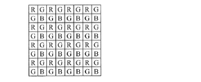
カラー画像の撮像には、光の三原色に相当する赤(R)、緑(G)及び青(B)の3つの異なる波長情報が必要となる。一方、撮像装置は、一つの撮像素子によりカラー画像を撮像する。従来技術では、撮像装置は、単一のカラーフィルタを使用して、一つの撮像素子によりカラー画像を撮像する。本特許では、可視光のうち特定の波長域を通過させ特定の波長域を阻止するフィルタ、および、可視光のすべての波長域を通過させるフィルタをカラーフィルタとよぶ。前記単一のカラーフィルタは、撮像素子の各画素に対応する領域を有する。前記各画素に対応する領域は、赤(R)、緑(G)又は青(B)のいずれか一つの波長域の光を透過する。前記単一のカラーフィルタにおける赤(R)、緑(G)及び青(B)の分布パターンとしては図20に示すベイヤー配列が広く利用されてきた。ベイヤー配列では、人間の視覚特性に近いG画素を全体の画素の1/2、R画素およびB画素をそれぞれ全体の画素の1/4となるようにカラーフィルタが配置されている。撮像装置は、前記単一のカラーフィルタを使用して、撮像素子の画素毎に赤(R)、緑(G)又は青(B)のいずれか一つの波長情報を取得する。そして、カラー画像生成装置は、前記撮像装置から受信した波長情報をデモザイキングという処理により、カラー画像に復元する。 In order to capture a color image, three different wavelength information of red (R), green (G), and blue (B) corresponding to the three primary colors of light are required. On the other hand, the imaging device captures a color image with one imaging element. In the prior art, the imaging device captures a color image with a single image sensor using a single color filter. In this patent, a filter that passes a specific wavelength range of visible light and blocks a specific wavelength range, and a filter that passes all the wavelength ranges of visible light are called color filters. The single color filter has a region corresponding to each pixel of the image sensor. The region corresponding to each pixel transmits light in any one wavelength region of red (R), green (G), and blue (B). As a distribution pattern of red (R), green (G), and blue (B) in the single color filter, the Bayer arrangement shown in FIG. 20 has been widely used. In the Bayer array, color filters are arranged such that G pixels close to human visual characteristics are ½ of all pixels, and R pixels and B pixels are each ¼ of all pixels. The imaging device acquires any one wavelength information of red (R), green (G), and blue (B) for each pixel of the imaging device using the single color filter. Then, the color image generation apparatus restores the wavelength information received from the imaging apparatus into a color image by a process called demosaicing.
特許文献1は、上記のベイヤー配列のカラーフィルタを備えた撮像システムを開示する(コラム2の52行目から57行目)。特許文献1の撮像システムの入力部は、撮像素子の各画素に対して赤(R)、緑(G)又は青(B)のいずれかの一つの波長情報しか取得できない。そのため、特許文献1の撮像システムのデータ補間及び記録部は、デジタル信号プロセッサーにおいてカラー画像を復元する際に、波長情報のデータ補間を行う(コラム1の54行目から60行目、コラム4の15行目から33行目)。しかし、前記データ補間により取得していない色の情報を、別の色情報から擬似的に補間するため、偽色が発生し得る。
特許文献2は、単一のカラーフィルタを使用した画像処理システムを開示する。前記単一のカラーフィルタでは、撮像素子の各画素に対応する領域において赤(R)、緑(G)又は青(B)がランダムなパターンで分布している(段落0032、段落0042、図13)。このため、撮像素子の各画素に対して赤(R)、緑(G)又は青(B)のいずれかの一つの波長情報しか取得できない。特許文献2の画像処理システムの光変換器は、画像センサで得られた原画像の光特性を変換してサンプリングすることにより、サンプルデータ集合を生成する(段落0027から0028)。そして、特許文献2の画像処理システムのデータ処理装置は、サンプルデータ集合に対して圧縮センシング技術を適用してカラー画像の復元を行う(段落0030)。特許文献2でも、特許文献1と同様に、取得していない色の情報を、別の色情報から擬似的に補間する必要があるため、偽色が発生し得る。
前述の従来技術では、上記のように更なる改善が必要とされていた。 In the above-described prior art, further improvement is required as described above.
本開示の一態様の撮像装置は、
被写体からの光を集光する結像光学系と、
複数の画素を有し、前記集光された光を受光して電気信号に変換する撮像素子と、
前記結像光学系及び前記撮像素子の間に配置され、異なる光透過率特性を有する複数のカラーフィルタと、
前記電気信号を符号化する送信データ圧縮回路と、を備え、
前記複数のカラーフィルタの全体の光透過率特性は、前記撮像素子の画素単位でランダムに異なり、
前記送信データ圧縮回路は、前記撮像素子の前記複数の画素の中の各画素に対応する前記複数のカラーフィルタの全体の光透過率特性の、各画素間で共通な波長特性に対する割合の逆数を用いて、前記各画素の電気信号を重み付けして符号化する、
撮像装置である。
An imaging device according to one embodiment of the present disclosure is provided.
An imaging optical system that collects light from the subject;
An image sensor having a plurality of pixels, receiving the collected light and converting it into an electrical signal;
A plurality of color filters disposed between the imaging optical system and the imaging device and having different light transmittance characteristics;
A transmission data compression circuit for encoding the electrical signal,
The overall light transmittance characteristics of the plurality of color filters are randomly different in pixel units of the image sensor,
The transmission data compression circuit calculates a reciprocal of a ratio of a total light transmittance characteristic of the plurality of color filters corresponding to each pixel of the plurality of pixels of the image sensor to a wavelength characteristic common to the pixels. And weighting and encoding the electrical signal of each pixel,
An imaging device.
なお、これらの包括的または具体的な態様は、システム、方法、集積回路、コンピュータプログラムまたはコンピュータ読み取り可能な記録媒体で実現されてもよく、装置、システム、方法、集積回路、コンピュータプログラムおよびコンピュータ読み取り可能な記録媒体の任意な組み合わせで実現されてもよい。コンピュータ読み取り可能な記録媒体は、例えばCD−ROM(Compact Disc−Read Only Memory)などの不揮発性の記録媒体を含む。 Note that these comprehensive or specific aspects may be realized by a system, a method, an integrated circuit, a computer program, or a computer-readable recording medium, and an apparatus, a system, a method, an integrated circuit, a computer program, and a computer readable medium. It may be realized by any combination of possible recording media. The computer-readable recording medium includes a non-volatile recording medium such as a CD-ROM (Compact Disc-Read Only Memory).
本開示によれば、更なる改善を実現できる。本開示の一態様の付加的な恩恵及び有利な点は本明細書及び図面から明らかとなる。この恩恵及び/又は有利な点は、本明細書及び図面に開示した様々な態様及び特徴により個別に提供され得るものであり、その1以上を得るために全てが必要ではない。 According to the present disclosure, further improvements can be realized. Additional benefits and advantages of one aspect of the present disclosure will become apparent from the specification and drawings. This benefit and / or advantage may be provided individually by the various aspects and features disclosed in the specification and drawings, and not all are required to obtain one or more thereof.
(本開示に係る一態様を想到するに至った経緯)
まず、図1Aから図1Dを参照しながら、本開示の一態様の着眼点について説明する。
(Background to coming up with one aspect of the present disclosure)
First, the point of focus of one aspect of the present disclosure will be described with reference to FIGS. 1A to 1D.
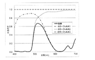
図1Aは、前記撮像素子の第1の画素に対応する複数のカラーフィルタ1から3の個々の光透過率特性及び前記撮像素子の第1の画素に対応する前記複数のカラーフィルタ1から3の全体の光透過率特性を示す図である。図1Bは、前記第1の画素とは異なる第2の画素に対応する前記複数のカラーフィルタ1から3の個々の光透過率特性及び前記撮像素子の第2の画素に対応する前記複数のカラーフィルタ1から3の全体の光透過率特性を示す図である。なお、第1画素に対応するカラーフィルタ1の厚さと第2画素に対応するカラーフィルタ1の厚さは異なり、かつ、第1画素に対応するカラーフィルタ2の厚さと第2画素に対応するカラーフィルタ2の厚さは異なり、かつ、第1画素に対応するカラーフィルタ3の厚さと第2画素に対応するカラーフィルタ3の厚さは異なる。また、「撮像素子の第1の画素に対応する複数のカラーフィルタ1から3の全体の光透過率特性」とは、例えば「光が撮像素子の第1の画素に対応する複数のカラーフィルタ1、カラーフィルタ2、カラーフィルタ3を透過した場合の光透過率特性」である。ここで、図1Aが示す前記第1の画素に対応する前記複数のカラーフィルタ1から3の全体の光透過率特性は、全波長域におけるいずれかの波長域において、図1Bが示す前記第2の画素に対応する前記複数のカラーフィルタ1から3の全体の光透過率特性と異なる。即ち、本態様では、前記複数のカラーフィルタ1から3の全体の光透過率特性は画素単位及び波長単位でランダムに異なっている。
FIG. 1A shows individual light transmittance characteristics of the plurality of
同様に、図1Aが示す前記第1の画素に対応する前記複数のカラーフィルタ1から3の中の各々の光透過率特性は、全波長域におけるいずれかの波長域において、図1Bが示す前記第2の画素に対応する前記複数のカラーフィルタ1から3の中の各々の光透過率特性と異なる。即ち、本態様では、前記複数のカラーフィルタ1から3の光透過率特性は画素単位及び波長単位でランダムに異なっている。上述のように、前記複数のカラーフィルタ1から3の全体の光透過率特性が画素単位及び波長単位でランダムに異なっているのは、このような光透過率特性を有する前記複数のカラーフィルタ1から3を組み合わせているからである。図1Aは前記第1の画素に対応し、図1Bは前記第2の画素に対応するが、これらは一例であり、前記第1の画素及び前記第2の画素以外の他の画素においても前記複数のカラーフィルタ1から3の全体の光透過率特性は画素単位及び波長単位でランダムに異なっている。
Similarly, the light transmittance characteristics of each of the plurality of
このように、前記複数のカラーフィルタ1から3の全体の光透過率特性のランダム性を画素単位及び波長単位で高めているのは、本態様の撮像装置から前記符号化された電気信号を入力した画像生成装置において、圧縮センシング技術を用いて元のカラー画像を再現する際に、前記ランダム性が高いほど元のカラー画像をより正確に再現することが可能となるからである。
As described above, the randomness of the overall light transmittance characteristics of the plurality of
続いて、前記被写体からの光は、前記複数のカラーフィルタ1から3を透過し、前記撮像素子において受光される。そして、前記受光された光の光強度は、前記撮像素子において前記電気信号に変換される。
Subsequently, light from the subject passes through the plurality of
ここで、特許文献1及び2の従来技術は、本態様とは異なり、一つの画素に対して赤(R)、緑(G)又は青(B)のいずれか一つの波長域の光を透過させる単一のカラーフィルタを用いる。そのため、前記単一のカラーフィルタの中でRの波長域の光を透過させる画素間では光透過率特性は等しい。同様に、前記単一のカラーフィルタの中でGの波長域の光を透過させる画素間、及び、前記単一のカラーフィルタの中でBの波長域の光を透過させる画素間でも光透過率特性は等しい。また、被写体が自然物の場合、前記被写体からの光の強度は一般的には急激に変化しないと仮定できる。その結果、前記単一のカラーフィルタの中の赤(R)と同一の波長域を透過した光を受光した近傍の画素同士の光強度の差分は、前記透過するカラーフィルタの光透過率特性が等しく、且つ、近傍の光同士では光強度が急激に変化しないため、小さくなる。同様に、緑(G)と同一の波長域を透過した光を受光した近傍の画素同士の光強度の差分、又は、青(B)と同一の波長域を透過した光を受光した近傍の画素同士の光強度の差分も、それぞれ、緑(G)又は青(B)の各々の光透過率特性が等しく、且つ、近傍の光同士では光強度が急激に変化しないため、小さくなる。このことを利用して、従来技術は、赤(R)、緑(G)又は青(B)の波長域毎に電気信号の差分を計算し、圧縮している。このように、従来技術では、前記カラーフィルタの光透過率特性の単位で電気信号を圧縮し、圧縮効率を上げようとしていると考えられる。
Here, the prior arts of
これに対して、本態様の撮像装置では、まず、カラー画像の再現性を高めるため、前記撮像素子の各画素に対応させて前記複数のカラーフィルタ1から3を設けている。ここで、前記複数のカラーフィルタ1から3の全体の光透過率特性は、画素単位でランダムに異なっている。このため、前記被写体からの光を前記複数のカラーフィルタ1から3に透過させることにより、前記被写体からの光の光強度は画素単位でランダムに変化する。従って、前述の従来技術のように、前記カラーフィルタの光透過率特性の単位で電気信号を圧縮することはできない。従って、カラー画像の再現性を高めつつ、圧縮効率を向上させ、伝送効率を改善するための工夫が必要となる。
On the other hand, in the imaging apparatus of this aspect, first, in order to improve the reproducibility of a color image, the plurality of
そこで、次に、本発明者は、前記撮像素子の前記複数の画素の中の各画素に対応する前記複数のカラーフィルタの全体の光透過率特性の、前記各画素間で共通な波長特性に対する割合の逆数を用いて、前記各画素の前記電気信号を重み付けすることを想到した。これにより、前記各画素に対応する前記電気信号を前記各画素間で共通な波長特性を基準とした値に変換している。 Therefore, next, the present inventor relates to the wavelength characteristic common to the pixels of the overall light transmittance characteristics of the plurality of color filters corresponding to the pixels of the plurality of pixels of the image sensor. It has been conceived that the electrical signal of each pixel is weighted using the reciprocal of the ratio. Thereby, the electric signal corresponding to each pixel is converted into a value based on a wavelength characteristic common to the pixels.
前記各画素に対応する前記複数のカラーフィルタの全体の光透過率特性の、前記各画素間で共通な波長特性に対する割合の逆数を用いて、前記複数のカラーフィルタを透過した各画素に対応する前記電気信号に前記重み付けする、ことの技術的意義を説明する。 The reciprocal of the ratio of the overall light transmittance characteristics of the plurality of color filters corresponding to the pixels to the wavelength characteristics common to the pixels is used to correspond to the pixels transmitted through the plurality of color filters. The technical significance of the weighting of the electrical signal will be described.
ここで、前記各画素間で共通な波長特性とは、前記重み付けの際に前記撮像素子のいずれの画素に対しても共通して用いられる基準としての波長特性であり、各波長域と光透過率等の値との関係で示される。 Here, the wavelength characteristic common to the respective pixels is a wavelength characteristic as a reference that is commonly used for all the pixels of the image sensor at the time of the weighting. It is shown in relation to values such as rate.
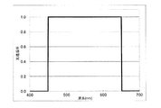
例えば、前記各画素間で共通な波長特性として、赤(R)、緑(G)及び青(B)に対応する全波長域において光透過率が等しい光透過率特性を用いることが考えられる。ここで、「赤(R)、緑(G)及び青(B)に対応する全波長域において光透過率が等しい」とは「赤色光の波長域における光透過率、緑色光の波長域における光透過率、青色光の波長域における光透過率が等しい」であることを意味してもよい。図1Cは、赤(R)、緑(G)及び青(B)に対応する全波長域において光透過率が等しい、仮想のカラーフィルタの光透過率特性の一例を示す図である。図1Cでは、横軸は波長を表し、縦軸は光透過率を表し、例えば、450nmから650nmの波長域において光透過率が「1」となっている。より具体的には、赤(R)の波長域(例えば、610nm〜650nm)の一部、緑(G)の波長域(例えば、500nm〜560nm)、及び、青(B)の波長域(例えば、450nm〜480nm)の各々において光透過率が「1」となっている。 For example, it is conceivable to use a light transmittance characteristic having the same light transmittance in all wavelength ranges corresponding to red (R), green (G), and blue (B) as a wavelength characteristic common to the respective pixels. Here, “the light transmittance is the same in all wavelength ranges corresponding to red (R), green (G) and blue (B)” means “the light transmittance in the wavelength range of red light and the wavelength range of green light”. It may mean that the light transmittance is equal to the light transmittance in the wavelength range of blue light. FIG. 1C is a diagram illustrating an example of the light transmittance characteristics of a virtual color filter having the same light transmittance in all wavelength ranges corresponding to red (R), green (G), and blue (B). In FIG. 1C, the horizontal axis represents the wavelength, and the vertical axis represents the light transmittance. For example, the light transmittance is “1” in the wavelength region of 450 nm to 650 nm. More specifically, a part of a red (R) wavelength range (for example, 610 nm to 650 nm), a green (G) wavelength range (for example, 500 nm to 560 nm), and a blue (B) wavelength range (for example, , 450 nm to 480 nm), the light transmittance is “1”.
また、前記各画素に対応する前記複数のカラーフィルタの全体の光透過率特性の、前記各画素間で共通な波長特性に対する割合は、各画素に対応する位置における前記複数のカラーフィルタの全体の波長特性と前記各画素間で共通な波長特性との積和演算で計算される。 The ratio of the overall light transmittance characteristics of the plurality of color filters corresponding to the pixels to the wavelength characteristics common to the pixels is the total of the plurality of color filters at the position corresponding to the pixels. Calculation is performed by the product-sum operation of the wavelength characteristic and the wavelength characteristic common to the pixels.
例えば、図1Aに示す前記第1の画素に対応する前記複数のカラーフィルタの全体の光透過率特性と図1Cに示す前記各画素間で共通な波長特性との積和は、上記のように図1Cでは、例えば、450nmから650nmの波長域において光透過率が「1」であるため、450nmから650nm波長の領域内で図1Aに示す前記複数のカラーフィルタの全体の光透過率特性を積分した値となる。図1Dは、図1Cに示す光透過率特性を用いて図1Aに示す前記複数のカラーフィルタの全体の光透過率特性を積和演算して得られた積分値を面積で示した図である。図1Dにおいて、前記積分値は斜線部の面積に対応する。 For example, the product sum of the overall light transmittance characteristics of the plurality of color filters corresponding to the first pixel shown in FIG. 1A and the wavelength characteristics common to the pixels shown in FIG. 1C is as described above. In FIG. 1C, for example, since the light transmittance is “1” in the wavelength region of 450 nm to 650 nm, the entire light transmittance characteristics of the plurality of color filters shown in FIG. 1A are integrated within the wavelength region of 450 nm to 650 nm. It becomes the value. FIG. 1D is a diagram showing an area of an integrated value obtained by multiply-accumulating the light transmittance characteristics of the plurality of color filters shown in FIG. 1A using the light transmittance characteristics shown in FIG. 1C. . In FIG. 1D, the integral value corresponds to the area of the shaded area.
上述したことを前提に、まず、各画素に対応する前記複数のカラーフィルタの全体の光透過率特性のすべてに対して、前記各画素に対応する前記複数のカラーフィルタの全体の光透過率特性の、前記各画素間で共通な波長特性に対する割合を算出する。 On the premise of the above, first, the entire light transmittance characteristics of the plurality of color filters corresponding to each pixel with respect to all the light transmittance characteristics of the plurality of color filters corresponding to each pixel. The ratio to the wavelength characteristic common to the pixels is calculated.
具体的には、例えば、前記各画素間で共通な波長特性として図1Cに示す波長特性を用いる場合、図1Aに示す前記第1の画素に対応する前記複数のカラーフィルタの全体の光透過率特性に対しては、図1Aに示す前記第1の画素に対応する前記複数のカラーフィルタの全体の光透過率特性の、図1Cに示す前記各画素間で共通な波長特性に対する割合が算出される。また、図1Bに示す前記第2の画素に対応する前記複数のカラーフィルタの全体の光透過率特性に対しては、図1Bに示す前記第2の画素に対応する前記複数のカラーフィルタの全体の光透過率特性の、図1Cに示す前記各画素間で共通な波長特性に対する割合が算出される。同様に、前記第1の画素及び前記第2の画素以外の各画素に対応する前記複数のカラーフィルタの全体の光透過率特性に対しても、前記各画素に対応する前記複数のカラーフィルタの全体の光透過率特性の、図1Cに示す前記各画素間で共通な波長特性に対する割合が算出される。 Specifically, for example, when the wavelength characteristic shown in FIG. 1C is used as the wavelength characteristic common to the pixels, the entire light transmittance of the plurality of color filters corresponding to the first pixel shown in FIG. 1A is used. For the characteristics, the ratio of the overall light transmittance characteristics of the plurality of color filters corresponding to the first pixel shown in FIG. 1A to the wavelength characteristics common to the pixels shown in FIG. 1C is calculated. The In addition, for the entire light transmittance characteristics of the plurality of color filters corresponding to the second pixels shown in FIG. 1B, the whole of the plurality of color filters corresponding to the second pixels shown in FIG. The ratio of the light transmittance characteristics to the wavelength characteristics common to the pixels shown in FIG. 1C is calculated. Similarly, with respect to the overall light transmittance characteristics of the plurality of color filters corresponding to the pixels other than the first pixel and the second pixel, the plurality of color filters corresponding to the pixels are also included. The ratio of the overall light transmittance characteristic to the wavelength characteristic common to the pixels shown in FIG. 1C is calculated.
「第1画素に対応にする複数のカラーフィルタの全体の光透過率特性の、各画素間で共通な波長特性に対する割合」とは、例えば、「図1Dに示す斜線部の面積」である。ただし、「第1画素に対応にする複数のカラーフィルタの全体の光透過率特性」とは、図1Aにおいて「全体、つまり実線の太字」で表された特性であり、「各画素間で共通な波長特性」は図1Cで示された特性である。 The “ratio of the overall light transmittance characteristics of the plurality of color filters corresponding to the first pixel to the wavelength characteristics common to the respective pixels” is, for example, “the area of the hatched portion shown in FIG. 1D”. However, “the entire light transmittance characteristic of the plurality of color filters corresponding to the first pixel” is a characteristic represented by “whole, that is, a bold bold line” in FIG. "Wave wavelength characteristic" is the characteristic shown in FIG. 1C.
これにより、前記各画素に対応する前記複数のカラーフィルタの全体の光透過率特性という前記各画素に個別の特性を、前記各画素間で共通な波長特性という前記各画素に共通の特性との関係で相対的に把握することができる。 Accordingly, the individual characteristics of the pixels, that is, the overall light transmittance characteristics of the plurality of color filters corresponding to the pixels, and the characteristics that are common to the pixels, that is, the wavelength characteristics that are common among the pixels. It can be grasped relatively by relationship.
しかし、これだけでは不十分である。なぜなら、前記各画素に対応する前記電気信号は、依然として、画素単位でランダムに異なる前記複数のカラーフィルタの全体の光透過率特性を基準として取得された電気信号のままだからである。そのため、本態様では、前記各画素に個別の特性を基準として取得された電気信号を、前記各画素間で共通な波長特性という前記各画素に共通の特性を基準とした値に変換している。 However, this is not enough. This is because the electrical signal corresponding to each pixel is still an electrical signal acquired on the basis of the entire light transmittance characteristics of the plurality of color filters that are randomly different for each pixel. Therefore, in this aspect, the electrical signal acquired based on the individual characteristics of each pixel is converted to a value based on the characteristics common to the pixels, which is a wavelength characteristic common to the pixels. .
即ち、本態様では、前記各画素に対応する前記複数のカラーフィルタの全体の光透過率特性の、前記各画素間で共通な波長特性に対する割合の逆数を算出している。ここで、前記各画素に対応する前記複数のカラーフィルタの全体の光透過率特性の、前記各画素間で共通な波長特性に対する割合は、前記各画素間で共通な波長特性に対して、前記各画素に対応する前記複数のカラーフィルタの全体の光透過率特性が占める割合を示す。従って、前記各画素に対応する前記複数のカラーフィルタの全体の光透過率特性の、前記各画素間で共通な波長特性に対する割合の逆数は、前記各画素に対応する前記複数のカラーフィルタの全体の光透過率特性に対して、前記各画素間で共通な波長特性が占める割合を示す。このため、前記各画素に対応する前記複数のカラーフィルタの全体の光透過率特性を基準として取得された前記電気信号に対して、前記各画素に対応する前記複数のカラーフィルタの全体の光透過率特性の、前記各画素間で共通な波長特性に対する割合の逆数を掛けること、即ち、前記重み付けをすることにより、前記各画素間で共通な波長特性を基準とした値に前記各画素に対応する前記電気信号を変換することができる。 That is, in this aspect, the reciprocal of the ratio of the overall light transmittance characteristics of the plurality of color filters corresponding to the pixels to the wavelength characteristics common to the pixels is calculated. Here, the ratio of the overall light transmittance characteristics of the plurality of color filters corresponding to the pixels to the wavelength characteristics common to the pixels is the wavelength characteristics common to the pixels. The ratio of the entire light transmittance characteristic of the plurality of color filters corresponding to each pixel is shown. Therefore, the reciprocal of the ratio of the overall light transmittance characteristics of the plurality of color filters corresponding to the pixels to the wavelength characteristics common to the pixels is the whole of the plurality of color filters corresponding to the pixels. The ratio of the wavelength characteristics common to the respective pixels to the light transmittance characteristics is shown. For this reason, the entire light transmission of the plurality of color filters corresponding to each pixel with respect to the electrical signal acquired with reference to the entire light transmittance characteristics of the plurality of color filters corresponding to the pixels. By multiplying the ratio of the rate characteristic with respect to the wavelength characteristic common to the pixels by the inverse of the ratio, that is, by applying the weighting, the value corresponding to the wavelength characteristic common to the pixels corresponds to each pixel. The electrical signal can be converted.
具体的には、例えば、前記各画素間で共通な波長特性として図1Cに示す光透過率特性を用いる場合、図1A及び図1Bに例示的に示すように、前記各画素に対応する前記複数のカラーフィルタの全体の光透過率特性をランダムに異ならせて、取得された前記各画素に対応する前記電気信号に対して、前記重み付けをすることにより、図1Cに示す前記各画素間で共通な波長特性を基準とした値に前記各画素に対応する前記電気信号を変換することができる。 Specifically, for example, when the light transmittance characteristic shown in FIG. 1C is used as a wavelength characteristic common to the pixels, the plurality of pixels corresponding to the pixels are exemplarily shown in FIGS. 1A and 1B. Commonly among the pixels shown in FIG. 1C by randomly varying the overall light transmittance characteristics of the color filters and weighting the electrical signals corresponding to the acquired pixels. The electrical signal corresponding to each pixel can be converted into a value based on a proper wavelength characteristic.
これにより、前記重み付けされた電気信号は、前記各画素間で共通な波長特性を有するカラーフィルタを使用して得られる電気信号と近似する。即ち、本態様では、前記重み付けにより、画素単位で異なる前記複数のカラーフィルタの全体の光透過率特性が、すべての画素に対応する位置において等しい波長特性、即ち、前記各画素間で共通な波長特性に変換されたと実質的に見なすことができる。このように、前記各画素に対応する前記重み付けした電気信号は、いずれも前記各画素間で共通な波長特性を基準とした値又はそれに近似した値となる。このため、光透過率特性が等しい画素間で電気信号の差分を計算し、圧縮率を高める従来技術と同程度の圧縮率を実現できる。この結果、本態様によると、前記重み付けした電気信号の差分を取ることにより、カラー画像の再現性を高めつつ、それによる伝送効率の低下を回避することができる。 Thereby, the weighted electrical signal approximates an electrical signal obtained using a color filter having a wavelength characteristic common to the pixels. That is, in this aspect, due to the weighting, the overall light transmittance characteristics of the plurality of color filters that are different in pixel units are equal in the positions corresponding to all the pixels, that is, a wavelength common to the pixels. It can be considered substantially converted to a characteristic. As described above, the weighted electrical signals corresponding to the respective pixels have values based on wavelength characteristics common to the respective pixels or values approximate thereto. For this reason, it is possible to realize a compression rate comparable to that of the conventional technique for calculating the difference of the electric signal between pixels having the same light transmittance characteristics and increasing the compression rate. As a result, according to this aspect, by taking the difference between the weighted electrical signals, it is possible to improve the reproducibility of the color image and avoid a decrease in the transmission efficiency due to this.
以上により、たとえ、カラー画像の再現性を高めるために、画素単位及び波長単位の光透過率特性をランダムに異ならせた複数のカラーフィルタを使用して前記電気信号を取得した場合であっても、解像度の低下及び偽色の発生を防止しつつ、一つの画素に対して赤(R)、緑(G)又は青(B)のいずれか一つの波長域の光を透過させる単一のカラーフィルタを使用する従来技術と同程度にまで伝送圧縮効率を向上させることができる。 As described above, even if the electrical signal is acquired using a plurality of color filters having light transmittance characteristics that are randomly changed in units of pixels and wavelengths in order to improve the reproducibility of a color image. A single color that transmits light in any one wavelength band of red (R), green (G), and blue (B) to one pixel while preventing a decrease in resolution and generation of false color. Transmission compression efficiency can be improved to the same extent as in the prior art using a filter.
以上の考察により、本発明者らは、以下に開示する各態様を想到するに至った。 Based on the above considerations, the present inventors have arrived at each aspect disclosed below.
(本開示の実施の形態の概要)
本開示の一態様の撮像装置は、
被写体からの光を集光する結像光学系と、
複数の画素を有し、前記集光された光を受光して電気信号に変換する撮像素子と、
前記結像光学系及び前記撮像素子の間に配置され、異なる第一群の光透過率特性を有する複数のカラーフィルタを含むフィルターユニットと、
前記電気信号を符号化する送信データ圧縮回路と、を備え、
前記フィルターユニット全体の光透過率特性は、前記撮像素子の画素単位でランダムに異なり、
前記送信データ圧縮回路は、前記撮像素子の前記複数の画素の中の各画素に対応する前記フィルターユニット全体の光透過率特性の、各画素間で共通な波長特性に対する割合の逆数を用いて、前記各画素の電気信号を重み付けして符号化する、ものである。
(Outline of Embodiment of the Present Disclosure)
An imaging device according to one embodiment of the present disclosure is provided.
An imaging optical system that collects light from the subject;
An image sensor having a plurality of pixels, receiving the collected light and converting it into an electrical signal;
A filter unit including a plurality of color filters disposed between the imaging optical system and the imaging device and having different first group light transmittance characteristics;
A transmission data compression circuit for encoding the electrical signal,
The light transmittance characteristic of the entire filter unit is randomly different for each pixel of the image sensor,
The transmission data compression circuit uses the reciprocal of the ratio of the light transmittance characteristic of the entire filter unit corresponding to each pixel of the plurality of pixels of the image sensor to the wavelength characteristic common to the pixels, The electrical signal of each pixel is weighted and encoded.
本開示の一態様によると、異なる第一群の光透過率特性を有する複数のカラーフィルタを含むフィルターユニットを設ける。従来のベイヤー配列などの画素毎に相互に異なる単一のカラーフィルタを使用した場合は、カラー画像を再現する際に取得していない色の情報を別の色情報からデータ補間するため、これに起因して偽色が発生する。一方で、本態様では、被写体からすべての色情報を含んだ光を受光するので、解像度の低下を防止しつつ偽色の発生を防止できる。 According to one aspect of the present disclosure, a filter unit including a plurality of color filters having different first group light transmittance characteristics is provided. When using a single different color filter for each pixel such as a conventional Bayer array, color information not acquired when reproducing a color image is interpolated from other color information. This causes false color. On the other hand, in this aspect, since light including all color information is received from the subject, generation of false colors can be prevented while preventing a decrease in resolution.
また、前記フィルターユニット全体の光透過率特性は、前記撮像素子の画素単位でランダムに異なる。これは、前記フィルターユニットに含まれている前記複数のカラーフィルタの波長単位の光透過率特性を、前記撮像素子の前記複数の画素の各々に対応する位置においてランダムに異ならせているからである。この結果、前記複数のカラーフィルタを含む前記フィルターユニット全体の光透過率特性は、画素単位だけでなく波長単位でもランダムに異なることとなる。これにより、前記被写体からの光の光透過率特性を、画素単位及び波長単位で相乗的にランダムに異ならせている。このようにランダム性を高めているのは、本態様の撮像装置から前記符号化された電気信号を入力した画像生成装置において、前記ランダム性が高いほど元のカラー画像をより正確に再現することが可能となるからである。具体的には、前記画像生成装置において圧縮センシング技術を用いてカラー画像を生成するが、圧縮センシング技術では、データをサンプリングする際によりランダムな状態でサンプリングすることで、復元したデータと元のデータとの差異がより小さくなる。この点に鑑みて、上記のように前記ランダム性を画素単位及び波長単位で相乗的に高めている。 Further, the light transmittance characteristics of the entire filter unit are randomly different for each pixel of the image sensor. This is because the light transmittance characteristics in units of wavelengths of the plurality of color filters included in the filter unit are randomly changed at positions corresponding to the plurality of pixels of the image sensor. . As a result, the light transmittance characteristics of the entire filter unit including the plurality of color filters are randomly different not only in pixel units but also in wavelength units. As a result, the light transmittance characteristics of light from the subject are changed synergistically and randomly at the pixel unit and the wavelength unit. The reason why the randomness is increased in this way is that the higher the randomness is, the more accurately the original color image is reproduced in the image generation apparatus that receives the encoded electrical signal from the imaging apparatus of this aspect. This is because it becomes possible. Specifically, a color image is generated by using the compressed sensing technology in the image generation device. In the compressed sensing technology, the restored data and the original data are sampled by sampling in a more random state when sampling the data. And the difference is smaller. In view of this point, the randomness is synergistically improved in units of pixels and wavelengths as described above.
さらに、前記送信データ圧縮回路は、前記撮像素子の前記複数の画素の中の各画素に対応する前記フィルターユニット全体の光透過率特性の、各画素間で共通な波長特性に対する割合の逆数を用いて、前記各画素の電気信号を重み付けして符号化する。これにより、前記重み付けされた電気信号は、前記各画素間で共通な波長特性を有するカラーフィルタを使用して得られる電気信号と近似する。このように、前記各画素に対応する前記重み付けした電気信号は、いずれも前記各画素間で共通な波長特性を基準とした値である。このため、光透過率特性が等しい画素間で電気信号の差分を計算し、圧縮率を高める従来技術と同程度の圧縮率を実現できる。これにより、たとえ、カラー画像の再現性を高めるために、画素単位及び波長単位の光透過率特性をランダムに異ならせたフィルターユニットを使用して前記電気信号を取得した場合であっても、解像度の低下及び偽色の発生を防止しつつ、一つの画素に対して赤(R)、緑(G)又は青(B)のいずれか一つの波長域の光を透過させる単一のカラーフィルタを使用する従来技術と同程度にまで伝送圧縮効率を向上させることができる。 Further, the transmission data compression circuit uses a reciprocal of a ratio of a light transmittance characteristic of the entire filter unit corresponding to each pixel of the plurality of pixels of the image sensor to a wavelength characteristic common to the pixels. Thus, the electric signals of the respective pixels are weighted and encoded. Thereby, the weighted electrical signal approximates an electrical signal obtained using a color filter having a wavelength characteristic common to the pixels. As described above, the weighted electrical signals corresponding to the respective pixels are values based on wavelength characteristics common to the respective pixels. For this reason, it is possible to realize a compression rate comparable to that of the conventional technique for calculating the difference of the electric signal between pixels having the same light transmittance characteristics and increasing the compression rate. Thereby, in order to improve the reproducibility of the color image, even when the electrical signal is acquired using a filter unit in which the light transmittance characteristics of the pixel unit and the wavelength unit are randomly changed, the resolution is improved. A single color filter that transmits light in any one wavelength band of red (R), green (G), and blue (B) to one pixel while preventing a decrease in color and generation of false color Transmission compression efficiency can be improved to the same extent as the conventional technology used.
一方で、本態様の撮像装置から前記符号化された電気信号を入力した画像生成装置において、前記撮像素子の前記複数の画素の中の各画素に対応する前記フィルターユニット全体の光透過率特性の、各画素間で共通な波長特性に対する割合の逆数を入手していれば、前記符号化された電気信号を元の重み付けされていない電気信号に再現できる。その結果、たとえ、カラー画像の再現性を高めるために、画素単位及び波長単位の光透過率特性をランダムに異ならせたフィルターユニットを使用して前記電気信号を取得した場合であっても、解像度の低下及び偽色の発生を防止しつつ、一つの画素に対して赤(R)、緑(G)又は青(B)のいずれか一つの波長域の光を透過させる単一のカラーフィルタを使用する従来技術と同程度にまで伝送圧縮効率を向上させることができる。 On the other hand, in the image generation device that receives the encoded electrical signal from the imaging device of this aspect, the light transmittance characteristics of the entire filter unit corresponding to each pixel of the plurality of pixels of the imaging device. If the reciprocal of the ratio with respect to the wavelength characteristic common to the respective pixels is obtained, the encoded electric signal can be reproduced as the original unweighted electric signal. As a result, in order to improve the reproducibility of the color image, even when the electrical signal is acquired using a filter unit in which the light transmittance characteristics of the pixel unit and the wavelength unit are randomly changed, the resolution is improved. A single color filter that transmits light in any one wavelength band of red (R), green (G), and blue (B) to one pixel while preventing a decrease in color and generation of false color Transmission compression efficiency can be improved to the same extent as the conventional technology used.
(実施の形態)
以下本開示の各実施の形態について、図面を参照しながら説明する。なお、各図面において、同じ構成要素については同じ符号が用いられている。
(Embodiment)
Hereinafter, each embodiment of the present disclosure will be described with reference to the drawings. In the drawings, the same reference numerals are used for the same components.
(第1の実施の形態)
(全体構成)
図2は、本開示の第1の実施の形態に係る撮像装置を示す概略ブロック図を示す。図2に示すように、撮像装置1は、結像光学系101、フィルターユニット102、撮像素子103、送信データ圧縮回路104及び送信回路105を備えている。撮像装置1は、被写体111からの光を受光する。「被写体111からの光」とは、被写体111から反射された光、又は、被写体111から発光された光を意味する。
(First embodiment)
(overall structure)
FIG. 2 is a schematic block diagram illustrating the imaging device according to the first embodiment of the present disclosure. As illustrated in FIG. 2, the
(結像光学系101)
結像光学系101は、少なくとも、レンズと、レンズ位置調整機構とを有する。図2において、レンズは、被写体111からの光を集光して、被写体111の像を撮像素子103において結像する。結像光学系101は、1枚のレンズを有していてもよいし、複数のレンズを有していてもよい。
(Imaging optical system 101)
The imaging
レンズ位置調整機構は、図示しないが、レンズの結像位置を調整するための機構である。レンズ位置調整機構として、例えば、レンズ位置を調整するアクチュエータ及びアクチュエータの駆動量を制御する制御回路(コントローラ)を用いることができる。 Although not shown, the lens position adjusting mechanism is a mechanism for adjusting the imaging position of the lens. As the lens position adjusting mechanism, for example, an actuator for adjusting the lens position and a control circuit (controller) for controlling the driving amount of the actuator can be used.
(フィルターユニット102)
図2に示すように、フィルターユニット102は、異なる光透過率特性を有する複数のカラーフィルタ、即ち、カラーフィルタ102a、カラーフィルタ102b及びカラーフィルタ102cを含む。なお、フィルターユニット102は、カラーフィルタ102a、カラーフィルタ102b及びカラーフィルタ102c以外の光学要素を含んでいてもよい。フィルターユニット102は、結像光学系101から入射した光が撮像素子103に至るまでの光路上に配置される。典型的には、フィルターユニット102は、撮像素子103の前面に接して配置される。なお、ここで「撮像素子103の前面」とは、撮像素子103の上面、又は撮像素子103の受光面としても規定されうる。
(Filter unit 102)
As shown in FIG. 2, the
フィルターユニット102は、撮像素子103に入射する光を波長的にも空間的にもランダムに受光するために用いられる。カラーフィルタ102aから102cは、例えば、色材の三原色に対応する3枚のカラーフィルタ、即ち、シアン(C)の波長域に対応するカラーフィルタ、マゼンダ(M)の波長域に対応するカラーフィルタ、及び、イエロー(Y)の波長域に対応するカラーフィルタに対応している。
The
また、図2に示すように、カラーフィルタ102aから102cはそれぞれカットフィルムを有している。ここで、カットフィルムとは、1層あたり所定の光吸収率特性を有する材質を任意の厚さに積層して構成されるフィルムをいう。
As shown in FIG. 2, each of the
カラーフィルタ102aから102cの各々の厚さは、図2に示すように、均一ではない。ここで、「厚さ」は、各カラーフィルタを透過する光の光軸に平行な方向に沿う、各カラーフィルタのカットフィルムの長さに対応する。このように、カラーフィルタ102aから102cの各々の厚さを画素単位でランダムに異ならせることにより、フィルターユニット102全体の光透過率特性は画素単位及び波長単位でランダムに異なることになる。これは、画像生成装置(図7)においてカラー画像の再現性を高めるためである。
The thickness of each of the
このように、本実施態様は、まず、第一フェーズとして、フィルターユニット102全体の光透過率特性を画素単位及び波長単位でランダムに異ならせ、被写体111からの光をフィルターユニット102に透過させることにより、被写体111からの光の光強度を画素単位でランダムに変化させている。これにより、画像生成装置(図7)においてカラー画像の再現性を高めることができる。
As described above, according to the present embodiment, first, as the first phase, the light transmittance characteristics of the
なお、図2では、3枚のカラーフィルタを組み合わせたフィルターユニット102を記載しているが、これは一例である。組み合わせるカラーフィルタの数は3枚に限られない。フィルターユニット102の更なる詳細は後に説明する。
In FIG. 2, the
(撮像素子103)
図2において、撮像素子103は、複数の画素を有し、結像光学系101が集光した光を複数の各画素において受光し、電気信号に変換する。電気信号は画素毎に取得される。以下、撮像素子103において取得された電気信号を「変調画像」とも表記しうる。撮像素子103は、レンズの焦点距離に配置される。
(Image sensor 103)
In FIG. 2, the
(送信データ圧縮回路104)
図2において、送信データ圧縮回路104は、入力部106、メモリ107及び制御部108を備えている。入力部106は、撮像素子103が取得した各画素の電気信号を撮像素子103から受け取る。
(Transmission data compression circuit 104)
In FIG. 2, the transmission
図2において、メモリ107は、各画素に対応するフィルターユニット102全体の光透過率特性の、前記各画素間で共通な波長特性に対する割合の逆数(以下、「重み」と表記しうる)を保持している。この「重み」を示す情報を「変調情報」とする。前記変調情報の更なる詳細は後に説明する。
In FIG. 2, the
図2において、制御部108は、重み付け部109と符号化部110とを備える。重み付け部109は、変調情報を用いて、前記電気信号を重み付けする。符号化部110は、前記重み付けされた電気信号を符号化することでデータ圧縮を行う。
In FIG. 2, the
このように、本実施態様は、第二フェーズとして、各画素に対応する電気信号の値を、前記重み付けすることによって、前記各画素間で共通な波長特性を有するカラーフィルタを使用して得られる電気信号と近似する。これにより、たとえ、カラー画像の再現性を高めるために、画素単位及び波長単位の光透過率特性をランダムに異ならせたフィルターユニット102を使用して前記電気信号を取得した場合であっても、解像度の低下及び偽色の発生を防止しつつ、一つの画素に対して赤(R)、緑(G)又は青(B)のいずれか一つの波長域の光を透過させる単一のカラーフィルタを使用する従来技術と同程度にまで伝送圧縮効率を向上させることができる。
Thus, this embodiment is obtained using the color filter which has a wavelength characteristic common among each said pixel by weighting the value of the electric signal corresponding to each pixel as a 2nd phase. Approximate electrical signal. Thereby, in order to improve the reproducibility of the color image, even when the electrical signal is acquired using the
尚、上記の重み付け及び符号化の更なる詳細は後(図10)に説明する。 Further details of the above weighting and encoding will be described later (FIG. 10).
(送信回路105)
図2において、送信回路105は、変調情報と、送信データ圧縮回路104が符号化した符号化電気信号とを、撮像装置1の外部の画像生成装置(図7)に送信する。送信は有線および無線のいずれでもよい。なお、本実施の形態では、撮像装置1と画像生成装置(図7)間で、概ねリアルタイムで変調情報及び符号化電気信号が送受信されて処理が行われていることを想定している。しかしながら、変調情報を保持するメモリ107以外に、符号化電気信号を保存する記憶装置(例えば、ハードディスクドライブ)をさらに設けることにより、非リアルタイムで処理を行っていてもよい。
(Transmission circuit 105)
In FIG. 2, the
次に、図2から5を参照しながら、フィルターユニット102をより詳細に説明する。
Next, the
図3は、カラーフィルタ102a、カラーフィルタ102b及びカラーフィルタ102cの光透過率特性を例示的に示す図である。図3に示すように、カラーフィルタ102aから102cは異なる光透過率特性を有する。ここで、異なる光透過率特性とは、波長域毎に光透過率が異なることをいう。
FIG. 3 is a diagram exemplarily showing light transmittance characteristics of the
また、図3に示すように、カラーフィルタ102aから102cの各々の光透過率特性は、いずれかの波長において、各カラーフィルタの厚さが変化しても変化しない、即ち、光吸収率が0%であるとしている。具体的には、例えば、図3では、カラーフィルタ102aが光透過率100%となる波長域は波長450nm前後であり、カラーフィルタ102bが光透過率100%となる波長域は波長640nm前後であり、カラーフィルタ102cが光透過率100%となる波長域は波長580nm前後である。また、カラーフィルタ102aから102cの各々の光透過率は、100%、即ち、光吸収率が0%となっている。
Further, as shown in FIG. 3, the light transmittance characteristics of each of the
なお、いずれかの波長において、光吸収率が「0%」であることは理想的である。しかし、カットフィルムは、その光吸収率が数%程度であっても、本実施形態のカットフィルムとして機能し得る。例えば、現実に光吸収率が0から2%の範囲内であれば、光吸収率は0%であるとして取り扱うことができる。同様に、いずれかの波長において、光透過率が「100%」であることは理想的である。しかし、光透過率が98%以上100%以下の範囲内であれば、光透過率は100%であるとして取り扱うことができる。 It is ideal that the light absorption rate is “0%” at any wavelength. However, the cut film can function as the cut film of the present embodiment even if its light absorption rate is about several percent. For example, if the light absorption rate is actually in the range of 0 to 2%, it can be handled that the light absorption rate is 0%. Similarly, it is ideal that the light transmittance is “100%” at any wavelength. However, if the light transmittance is in the range of 98% to 100%, the light transmittance can be handled as 100%.
なお、図2において、カラーフィルタ102aから102cは順に積層して構成されている。例えば、カラーフィルタ102cを例に説明すると、カラーフィルタ102bを積層する際の支持のため、カラーフィルタ102cのカットフィルムが存在しない箇所に、カラーフィルタ102cの光透過率または光吸収率に実質的に影響を与えない光学部材を充填してもよい。他のカラーフィルタ102a及びカラーフィルタ102bについても同様である。よって、各カットフィルムの光学特性が、カラーフィルタ102aから102cの各々の光学特性を決定する。
In FIG. 2, the
次に、フィルターユニット102の光透過率特性と、カラーフィルタ102aから102cの各々の光透過率特性及びカットフィルムの厚さとの関係について説明する。波長λに関する、カラーフィルタ102aのカットフィルムの光透過率特性をC1(λ)、カラーフィルタ102bのカットフィルムの光透過率特性をC2(λ)、カラーフィルタ102cのカットフィルムの光透過率特性をC3(λ)とする。また、画素位置(u,v)に対応するカラーフィルタ102aのカットフィルムの厚さをT1(u,v)、カラーフィルタ102bのカットフィルムの厚さをT2(u,v)、カラーフィルタ102cのカットフィルムの厚さをT3(u,v)とする。この場合、画素位置(u,v)に対応するフィルターユニット102全体の光透過率特性x(λ, u,v)は、次式で表現される。なお、記載の簡潔化のため、カットフィルムの厚さを、便宜的に「カラーフィルタの厚さ」と記述する。

ただし、Φ(C(λ),T(u,v))は、カラーフィルタの光透過率特性C(λ)とカラーフィルタの厚さT(u,v)から決まる、波長λの光透過率を示す関数である。また、Φ(C(λ),T(u,v))は、C(λ)に含まれる光吸収率が0、または、T(u,v)が0のときに固定値をとる関数である。具体的には、通常、カラーフィルタの厚さが増えると、光透過率は低下するが、カラーフィルタの光吸収率が0の場合はカラーフィルタの厚さにかかわらず光透過率が固定値となる。また、カラーフィルタを設置しない(T(u,v)=0)の場合も光透過率が固定値になる。 However, Φ (C (λ), T (u, v)) is the light transmittance of wavelength λ determined by the light transmittance characteristic C (λ) of the color filter and the thickness T (u, v) of the color filter. It is a function which shows. Φ (C (λ), T (u, v)) is a function that takes a fixed value when the light absorption rate included in C (λ) is 0 or T (u, v) is 0. is there. Specifically, normally, as the thickness of the color filter increases, the light transmittance decreases, but when the light absorption rate of the color filter is 0, the light transmittance is a fixed value regardless of the thickness of the color filter. Become. The light transmittance is also a fixed value when no color filter is installed (T (u, v) = 0).
数1から、カラーフィルタ102aから102cの厚さを画素単位でランダムに異ならせることにより、画素単位及び波長単位で光透過率特性がランダムに異なるフィルターユニット102を実現することができる。ここで、「画素単位及び波長単位で光透過率特性がランダムに異なる」とは、撮像素子103の第1の複数の画素に対応する領域及び第1の複数の画素に対応する領域とは異なる第2の複数の画素に対応する領域間における光透過率の相関係数の絶対値が、画素単位及び波長単位のいずれにおいても1未満であることを意味する。前記相関係数の絶対値は、0〜0.2程度であってもよい。
From
ここで、カラーフィルタ102aから102cの各々の厚さは、厚さ0%(フィルタを配置しない)から最大厚さ100%まで一様分布となるように設定する。ここで、「厚み0%から100%まで一様分布」とは、厚み0%から100%までの出現数が等しい分布を意味する。図4は、厚み0%から100%まで一様分布となるように各画素の厚みを設定した各カラーフィルタの一例を示す模式図である。図4(a)は、撮像素子103の各画素に対応する位置におけるカラーフィルタ102aの厚みの一例を示す模式図である。図4(b)は、撮像素子103の各画素に対応する位置におけるカラーフィルタ102bの厚みの一例を示す模式図である。図4(c)は、撮像素子103の各画素に対応する位置におけるカラーフィルタ102cの厚みの一例を示す模式図である。図4(a)から図4(c)に示すように、撮像素子103の各画素に対応する位置における各カラーフィルタの厚みは、画素単位でランダムに異なっている。このように、一様分布に従う乱数、即ち、一様乱数に基づいて、撮像素子103の各画素に対応する位置における各カラーフィルタの厚みを設定することで、数1に従い、画素単位及び波長単位で光透過率特性がランダムに異なるフィルターユニット102を実現することができる。
Here, the thickness of each of the
ここで、特許文献2の従来技術は、赤(R)、緑(G)又は青(B)の各領域がランダムに配置され、かつ、一つの画素に対して赤(R)、緑(G)又は青(B)のいずれか一つの波長域の光を透過させる単一のカラーフィルタを用いる。そのため、前記単一のカラーフィルタの中でRの波長域の光を透過させる画素間では光透過率特性は等しい。同様に、前記単一のカラーフィルタの中でGの波長域の光を透過させる画素間、及び、前記単一のカラーフィルタの中でBの波長域の光を透過させる画素間でも光透過率特性は等しい。従って、特許文献2の従来技術では、画素単位では光透過率特性はランダムに異なるが、波長単位では光透過率特性がランダムに異ならない。
Here, in the prior art of
一方、本態様の実施形態では、上述のようにフィルターユニット102を構成することで、画素単位だけでなく、波長単位にも一様乱数によるランダムサンプリングを実現することができる。
On the other hand, in the embodiment of the present aspect, by configuring the
尚、各カラーフィルタの厚さの設定には、一様分布以外の分布を用いてもよい。例えば、厚さ50%を平均とした正規分布(ガウス分布)で設定してもかまわない。図5は、厚み50%を平均とした正規分布(ガウス分布)となるように各画素の厚みを設定した各カラーフィルタの一例を示す模式図である。図5(a)は、撮像素子103の各画素に対応する位置におけるカラーフィルタ102aの厚みの一例を示す模式図である。図5(b)は、撮像素子103の各画素に対応する位置におけるカラーフィルタ102bの厚みの一例を示す模式図である。図5(c)は、撮像素子103の各画素に対応する位置におけるカラーフィルタ102cの厚みの一例を示す模式図である。図5(a)から図5(c)に示すように、撮像素子103の各画素に対応する位置における各カラーフィルタの厚みは、画素単位でランダムに異なっている。このように、正規分布に従う乱数、即ち、正規乱数に基づいて、撮像素子103の各画素に対応する位置における各カラーフィルタの厚みを設定することで、数1に従い、画素単位及び波長単位で光透過率特性がランダムに異なるフィルターユニット102を実現することができる。これにより、画素単位及び波長単位で正規乱数によるランダムサンプリングを実現することができる。
A distribution other than the uniform distribution may be used for setting the thickness of each color filter. For example, a normal distribution (Gaussian distribution) with an average thickness of 50% may be set. FIG. 5 is a schematic diagram illustrating an example of each color filter in which the thickness of each pixel is set so as to obtain a normal distribution (Gaussian distribution) with an average thickness of 50%. FIG. 5A is a schematic diagram illustrating an example of the thickness of the
次に、電気信号の重み付けの際に基準となる各画素間で共通な波長特性に関して、図1Cに示す赤(R)、緑(G)及び青(B)に対応する全波長域において光透過率が等しい光透過率特性以外の例を説明する。 Next, regarding the wavelength characteristics common among the pixels serving as the reference when the electric signal is weighted, light transmission is performed in all wavelength ranges corresponding to red (R), green (G), and blue (B) shown in FIG. 1C. An example other than the light transmittance characteristics having the same rate will be described.
図6Aは、前記各画素間で共通な波長特性の一例として比視感度を表した波長特性を示す図である。比視感度とは、人間の目が光の波長ごとの明るさを感じる強さを数値で表したものである。前記波長特性においては、図6Aに示すように、緑(G)に対応する550nm近傍の波長域において光強度が大きい。 FIG. 6A is a diagram illustrating wavelength characteristics representing specific luminous efficiency as an example of wavelength characteristics common to the respective pixels. Specific luminous efficiency is a numerical value representing the strength with which the human eye feels the brightness of each wavelength of light. In the wavelength characteristic, as shown in FIG. 6A, the light intensity is high in the wavelength region near 550 nm corresponding to green (G).
図6Bは、赤(R)及び青(B)に対応する波長域においては光透過率が0であり、緑(G)に対応する波長域のみ光透過率が0超である、仮想のカラーフィルタの光透過率特性の一例を示す図である。即ち、前記光透過率特性は、緑(G)に対応する波長域のバンドパスフィルタが有する光透過率特性と同一である。前記光透過率特性においては、図6Cに示すように、緑(G)に対応する550nm近傍の波長域において、光透過率が1であり、それ以外の波長域においては、光透過率が0である。 FIG. 6B shows a virtual color in which the light transmittance is 0 in the wavelength range corresponding to red (R) and blue (B), and the light transmittance is more than 0 only in the wavelength range corresponding to green (G). It is a figure which shows an example of the light transmittance characteristic of a filter. In other words, the light transmittance characteristic is the same as the light transmittance characteristic of the bandpass filter in the wavelength region corresponding to green (G). In the light transmittance characteristic, as shown in FIG. 6C, the light transmittance is 1 in the wavelength region near 550 nm corresponding to green (G), and the light transmittance is 0 in the other wavelength regions. It is.
図6Cは、レッド特性とブルー特性との差分特性を表した波長特性の一例を示す図である。前記波長特性は、レッド特性とブルー特性との差分、即ち、色差を示すものである。前記波長特性においては、図6Cに示すように、約570nm以下の波長域においては値が0より大きく、一方、約570nm以上の波長域においては値が0より小さい。 FIG. 6C is a diagram illustrating an example of a wavelength characteristic representing a difference characteristic between a red characteristic and a blue characteristic. The wavelength characteristic indicates a difference between the red characteristic and the blue characteristic, that is, a color difference. In the wavelength characteristic, as shown in FIG. 6C, the value is larger than 0 in the wavelength region of about 570 nm or less, while the value is smaller than 0 in the wavelength region of about 570 nm or more.
なお、図1C、及び図6Aから図6Cに示す波長特性は例に過ぎず、各画素間で共通な波長特性はこれらに限られない。 The wavelength characteristics shown in FIG. 1C and FIGS. 6A to 6C are merely examples, and the wavelength characteristics common to the respective pixels are not limited to these.
次に、図7を参照しつつ、本開示の一実施の形態に係る撮像システムに用いられる画像生成装置に関して説明する。 Next, an image generation device used in an imaging system according to an embodiment of the present disclosure will be described with reference to FIG.
図7は、本開示の第1の実施の形態に係る撮像システムに用いられる画像生成装置2を示す概略ブロック図である。図7に示すように、画像生成装置2は、受信回路201、受信データ復号回路202、カラー画像生成回路203および出力インターフェース装置204を備えている。
FIG. 7 is a schematic block diagram illustrating the
(受信回路201)
受信回路201は、撮像装置1から出力された変調情報と符号化電気信号とを受け取る。受信回路201と送信回路105との間の通信は、有線でも無線でも構わない。なお、送信回路105が変調情報と符号化電気信号を有線で送信したとしても、有線通信を無線通信に変換する機器を経由することにより、受信回路201がこれらの情報を無線で受信してもよい。その逆も同様である。
(Receiving circuit 201)
The receiving
(受信データ復号回路202)
図7に示すように、受信データ復号回路202は、メモリ205、制御部206及び出力部207を備えている。メモリ205は、受信回路201から受け取った変調情報を保持する。
(Received data decoding circuit 202)
As shown in FIG. 7, the reception
図7に示すように、制御部206は、復号化部208と重み付け除去部209とを備えている。復号化部208は、符号化電気信号を復号化する(第三フェーズ)。重み付け除去部209は、メモリ205から取得した変調情報を利用して、復号化された電気信号から重み付けを除去する(第四フェーズ)。ここで、前記第三フェーズは撮像装置1における前記第二フェーズに対応し、前記第四フェーズは撮像装置1における前記第一フェーズに対応する。即ち、前記第三フェーズにおいて得られた復号化された電気信号は、重み付けされた電気信号、即ち、前記各画素間で共通な波長特性を有するカラーフィルタを使用して得られる電気信号に近似した値に対応する。そのため、このままでは、カラー画像の再現性を高めることはできない。次に、前記第四フェーズにおいて、重み付け除去部209が前記変調情報を用いて前記復号化された電気信号から重み付けを除去することで、被写体111からの光がフィルターユニット102を透過した後の値を得ることができる。
As illustrated in FIG. 7, the
その結果、撮像装置1から符号化電気信号を入力した画像生成装置2において、変調情報を入手していれば、復号化後の電気信号を元の重み付けされていない電気信号に再現できる。このように、たとえ、画像生成装置2が、カラー画像の再現性を高めるために、画素単位及び波長単位の光透過率特性をランダムに異ならせたフィルターユニット102を使用して前記電気信号を撮像装置1から取得した場合であっても、解像度の低下及び偽色の発生を防止しつつ、一つの画素に対して赤(R)、緑(G)又は青(B)のいずれか一つの波長域の光を透過させる単一のカラーフィルタを使用する従来技術と同程度にまで伝送圧縮効率を向上させることができる。
As a result, if the modulation information is obtained in the
尚、上記の復号化及び重み付け除去の更なる詳細は後(図12)に説明する。 Further details of the above decoding and weighting removal will be described later (FIG. 12).
出力部207は、重み付けが除去された電気信号、即ち、変調画像をカラー画像生成回路203に送信する。
The
(カラー画像生成回路203)
図7において、カラー画像生成回路203は、受信データ復号回路202から取得した変調画像に基づいてカラー画像を生成する。また、カラー画像生成回路203は、生成されたカラー画像を出力インターフェース装置204に送る。カラー画像生成回路203の更なる詳細は後に説明する。
(Color image generation circuit 203)
In FIG. 7, the color
(出力インターフェース装置204)
出力インターフェース装置204は、映像出力端子である。出力インターフェース装置204は、カラー画像を、デジタル信号として、又は、アナログ信号として画像生成装置2の外部に出力する。
(Output interface device 204)
The
以上のように構成された本開示の第1実施形態における撮像装置1及び画像生成装置2を含む撮像システムについて、以下、その動作を説明する。
The operation of the imaging system including the
図8は、本開示の一実施の形態に係る撮像装置1及び画像生成装置2の間の処理シーケンスを示すシーケンス図である。
FIG. 8 is a sequence diagram illustrating a processing sequence between the
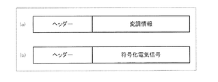
図9は、変調情報および符号化電気信号を伝送するための伝送フォーマットを例示的に示す模式図である。図9(a)は、変調情報が記述された伝送フォーマットを例示的に示す模式図である。また、図9(b)は、符号化電気信号が記述された伝送フォーマットを例示的に示す模式図である。 FIG. 9 is a schematic diagram exemplarily showing a transmission format for transmitting the modulation information and the encoded electric signal. FIG. 9A is a schematic diagram exemplarily showing a transmission format in which modulation information is described. FIG. 9B is a schematic diagram exemplarily showing a transmission format in which an encoded electric signal is described.
まず、撮像装置1の撮像素子103は、結像光学系101が集光した光を複数の各画素において受光し、電気信号に変換する(S801)。
First, the
撮像装置1の送信データ圧縮回路104は、メモリ107から取得した変調情報を用いて前記電気信号を重み付けする(S802)。
The transmission
撮像装置1の送信データ圧縮回路104は、前記重み付けされた電気信号を符号化する(S803)。
The transmission
撮像装置1の送信回路105は、画像生成装置2に接続される1回目の通信では、前記変調情報を図9(a)で表された伝送フォーマットを用いて画像生成装置2に送信し、及び、前記符号化された電気信号を図9(b)で表された伝送フォーマットを用いて画像生成装置2に送信する(S804)。ここで、撮像装置1は、前記変調情報の代わりに、前記変調情報を指定する指定情報を送信してもよい。この場合、画像生成装置2が予め前記変調情報を保持していれば、撮像装置1は、撮像装置1に対応する変調情報を指定できる。
The
画像生成装置2の受信回路201は、送信回路105から送信された前記変調情報及び前記符号化電気信号を受信する(S805)。
The
画像生成装置2のメモリ205は、前記変調情報を保持する(S806)。尚、上述のように、送信回路105が前記指定情報を送信した場合は、画像生成装置2のメモリ205は、前記指定情報を保持する(S806)。
The
画像生成装置2の復号化部208は、前記符号化電気信号を復号化する(S807)。尚、S807は、S806と並行して行ってもよいし、S806より先に行ってもよい。
The
画像生成装置2の重み付け除去部209は、メモリ205から取得した前記変調情報を用いて前記復号化された電気信号から重みを除去する(S808)。
The
また、S801、S802及びS803と同様に、撮像装置1は、結像光学系101が集光した光を電気信号に変換し(S809)、前記変調情報を用いて前記電気信号を重み付けし(S810)、前記重み付けされた電気信号を符号化する(S811)。
Similarly to S801, S802, and S803, the
ここで、撮像装置1の送信回路105は、画像生成装置2に接続される2回目の通信では、前記変調情報を出力せず、前記符号化された電気信号を図9(b)で表された伝送フォーマットを用いて画像生成装置2に送信する(S812)。前記変調情報は、撮像装置1において固有の固定値である。従って、送信回路105は、画像生成装置2に接続される2回目以降の通信では、画像生成装置2に前記変調情報を毎回送る必要はない。同様に、画像生成装置2に接続される1回目の通信において送信回路105が前記指定情報を送信した場合は、送信回路105は、画像生成装置2に接続される2回目以降の通信において、画像生成装置2に前記指定情報を毎回送る必要はない。
Here, the
次に、画像生成装置2は、送信回路105から送信された前記符号化電気信号を受信する(S813)。ここではS805と異なり、画像生成装置2は、前記変調情報は受信しない。これは、前記変調情報は、S806において、画像生成装置2のメモリ205に保持されているからである。続いて、前記符号化電気信号を復号化し(S814)、メモリ205から取得した前記変調情報を用いて前記復号化された電気信号から重みを除去する(S815)。
Next, the
次に、図10及び図11を参照しながら、送信データ圧縮回路104の動作をより詳細に説明する。図10は、本開示の第1の実施の形態に係る撮像装置1における電気信号の符号化処理を示すフローチャートである。
Next, the operation of the transmission
図10において、まず、送信データ圧縮回路104の入力部は、撮像素子103において取得された電気信号を取得する(S1001)。
In FIG. 10, first, the input unit of the transmission
送信データ圧縮回路104の重み付け部109は、メモリ107から変調情報を取得する(S1002)。前記変調情報は、上述のように、各画素に対応するフィルターユニット102全体の光透過率特性の、前記各画素間で共通な波長特性に対する割合の逆数、即ち、「重み」を表す情報である。より具体的には、前記変調情報は、画素位置(u,v)におけるフィルターユニット102全体の光透過率特性x(λ, u,v)と各画素間で共通な波長特性との積和演算の逆数として計算される値である。前記各画素間で共通な波長特性をT(λ)とすると、前記変調情報w(u,v)は、次式で計算できる。
ここで、フィルターユニット102全体の光透過率特性x(λ, u,v)を第二群の光透過率特性である赤(R)、緑(G)及び青(B)の線形和で表現することを考える。ここで、「光透過率特性である赤(R)、緑(G)及び青(B)」とは「仮想的に決定した赤色光の光透過率、仮想的に決定した緑色光の光透過率、仮想的に決定した青色光の光透過率」であることを意味してもよい。画素(u,v)に対応するフィルターユニット102全体のRの波長域に対応する光透過率特性の寄与度をTR(u,v)、画素(u,v)に対応するフィルターユニット102全体のGの波長域に対応する光透過率特性の寄与度をTG(u,v)、画素(u,v)に対応するフィルターユニット102全体のBの波長域に対応する光透過率特性の寄与度をTB(u,v)とすると、上記の数2は次式で表すことができる。
ただし、R(λ)は赤色光の光透過率特性,G(λ)は緑色光の光透過率特性及びB(λ)は青色光の光透過率特性を示している。R(λ)、G(λ)、B(λ)各々はこの装置、方法、システムを開発する開発者が仮想的に決定してもよい。例えば、
・R(λ)=光透過率が1(610nm≦λ≦650nm)、光透過率が0(λ<610nm、λ>650nm)
・G(λ)=光透過率が1(500nm≦λ≦560nm)、光透過率が0(λ<500nm、λ>560nm)
・B(λ)=光透過率が1(450nm≦λ≦480nm)、光透過率が0(λ<450nm、λ>480nm)
であってもよい。
However, R (λ) represents the light transmittance characteristic of red light, G (λ) represents the light transmittance characteristic of green light, and B (λ) represents the light transmittance characteristic of blue light. R (λ), G (λ), and B (λ) may be virtually determined by a developer who develops the apparatus, method, and system. For example,
R (λ) = light transmittance is 1 (610 nm ≦ λ ≦ 650 nm), light transmittance is 0 (λ <610 nm, λ> 650 nm)
G (λ) = light transmittance is 1 (500 nm ≦ λ ≦ 560 nm), light transmittance is 0 (λ <500 nm, λ> 560 nm)
B (λ) = light transmittance is 1 (450 nm ≦ λ ≦ 480 nm), light transmittance is 0 (λ <450 nm, λ> 480 nm)
It may be.
また、αR,αG及びαBは、各画素間で共通な波長特性の種類に応じて定まる定数である。例えば、各画素間で共通な波長特性が、赤(R)、緑(G)及び青(B)に対応する全波長域において光透過率が等しいものである場合、αR,αG及びαBは、以下の数4に示す値となる。
この場合、前記変調情報w(u,v)は、数4に示す係数を数3に示す式に代入して得られた値である。
In this case, the modulation information w (u, v) is a value obtained by substituting the coefficient shown in
また、各画素間で共通な波長特性が、比視感度を示す波長特性である場合、αR,αG及びαBは、以下の数5に示す値となる。
この場合、前記変調情報w(u,v)は、数5に示す係数を数3に示す式に代入して得られた値である。
In this case, the modulation information w (u, v) is a value obtained by substituting the coefficient shown in
また、各画素間で共通な波長特性が、赤(R)及び青(B)に対応する波長域においては光透過率が0であり、緑(G)に対応する波長域のみ光透過率が0超のものである場合、αR,αG及びαBは、以下の数6に示す値となる。
この場合、前記変調情報w(u,v)は、数6に示す係数を数3に示す式に代入して得られた値である。
In this case, the modulation information w (u, v) is a value obtained by substituting the coefficient shown in Equation 6 into the equation shown in
また、各画素間で共通な波長特性が各画素間で共通なレッド特性とブルー特性との差分特性を示すものである場合、αR,αG及びαBは、以下の数7に示す値となる。
この場合、前記変調情報w(u、v)は、数7に示す係数を数3に示す式に代入して得られた値である。
In this case, the modulation information w (u, v) is a value obtained by substituting the coefficient shown in Equation 7 into the equation shown in
続いてS1003に進む。S1003では、送信データ圧縮回路104の重み付け部109は、上述のように得られた前記変調情報w(u,v)を用いて前記電気信号を重み付けする。画素(u,v)に対応する前記電気信号をy(u,v)とすると、画素(u,v)に対応する重み付けした前記電気信号d(u,v)は次式で表現される。
ここで、S1003は、本実施態様の第二フェーズに対応する。このように、各画素に対応する電気信号の値y(u,v)を、前記変調情報w(u,v)を用いて前記重み付けすることによって得られた、重み付けした前記電気信号d(u,v)は、前記各画素間で共通な波長特性T(λ)を有するカラーフィルタを使用して得られる電気信号と近似する。 Here, S1003 corresponds to the second phase of the present embodiment. Thus, the weighted electrical signal d (u) obtained by weighting the value y (u, v) of the electrical signal corresponding to each pixel using the modulation information w (u, v). , v) approximates an electrical signal obtained using a color filter having a wavelength characteristic T (λ) common to the pixels.
即ち、まず、前記変調情報w(u,v)を算出することにより、前記各画素に対応するフィルターユニット102全体の光透過率特性x(λ, u,v)という前記各画素に個別の特性を、前記各画素間で共通な波長特性T(λ)という前記各画素に共通の特性との関係で相対的に把握することができる。ここで、数2の右辺の分母に対応する、画素位置(u,v)に対応するフィルターユニット102全体の光透過率特性x(λ, u,v)と各画素間で共通な波長特性との積和は、前記各画素間で共通な波長特性T(λ)に対して、前記各画素に対応するフィルターユニット102全体の光透過率特性x(λ, u,v)が占める割合を示す。数2に示すように、前記変調情報w(u,v)は前記割合の逆数である。従って、前記変調情報w(u,v)は、前記各画素に対応するフィルターユニット102全体の光透過率特性x(λ, u,v)に対して、前記各画素間で共通な波長特性T(λ)が占める割合を示す。
That is, first, by calculating the modulation information w (u, v), an individual characteristic for each pixel, which is the light transmittance characteristic x (λ, u, v) of the
このため、次に数8に示すように、前記各画素に対応するフィルターユニット102全体の光透過率特性x(λ, u,v)を基準として取得された前記電気信号y(u,v)に対して、前記変調情報w(u,v)を掛けること、即ち、前記重み付けをすることにより、前記各画素に個別の特性x(λ, u,v)を基準として取得された電気信号y(u,v)を、前記各画素間で共通な波長特性T(λ)という前記各画素に共通の特性を基準とした値d(u,v)に変換することができる。このように、前記各画素に対応する前記重み付けした電気信号d(u,v)は、いずれも前記各画素間で共通な波長特性T(λ)を基準とした値である。このため、光透過率特性が等しい画素間で電気信号の差分を計算し、圧縮率を高める従来技術と同程度の圧縮率を実現できる。
Therefore, as shown in the following equation 8, the electric signal y (u, v) acquired based on the light transmittance characteristic x (λ, u, v) of the
これにより、たとえ、カラー画像の再現性を高めるために、画素単位及び波長単位の光透過率特性をランダムに異ならせたフィルターユニット102を使用して前記電気信号を取得した場合であっても、解像度の低下及び偽色の発生を防止しつつ、一つの画素に対して赤(R)、緑(G)又は青(B)のいずれか一つの波長域の光を透過させる単一のカラーフィルタを使用する従来技術と同程度にまで伝送圧縮効率を向上させることができる。
Thereby, in order to improve the reproducibility of the color image, even when the electrical signal is acquired using the
次に、送信データ圧縮回路104の符号化部110は、ラスタスキャンの順序に従って、各画素に対応する前記重み付けした電気信号を順次符号化する(S1004からS1007)。
Next, the
ここで、図11を用いてラスタスキャンについて説明する。図11は、前記重み付けした電気信号を符号化する処理を説明するために用いられる、ラスタスキャンの順序を示す模式図である。尚、図11において、説明を簡略化するために、撮像素子103の画素数はN=16であるとしている。まず、図11のv=1において、左端の画素(u,v)=(1,1)から順次一つずつ右端の画素(u,v)=(4,1)に至るまで画素が選択される。次に、同様にv=2においても、左端の画素(u,v)=(2,1)から順次一つずつ右端の画素(u,v)=(4,2)に至るまで画素が選択される。そして、同様にv=3とその次のv=4においても左端の画素から順次一つずつ右端の画素に至るまで選択される。よって、最後に選択される画素は(u,v)=(4,4)の画素である。このような順序にて、送信データ圧縮回路104の符号化部110は、各画素に対応する前記重み付けした電気信号を順次符号化する。
Here, raster scanning will be described with reference to FIG. FIG. 11 is a schematic diagram showing the order of raster scanning used to describe the process of encoding the weighted electrical signal. In FIG. 11, in order to simplify the description, it is assumed that the number of pixels of the
S1004に戻り、送信データ圧縮回路104の符号化部110は、前記重み付けした電気信号の圧縮方法を選択するために、まず、着目画素に対して近傍画素が存在するか判断する。ここで、「近傍画素」とは、着目画素の左隣の画素を意味する。例えば、図11では、左端の画素である(u,v)=(1,1), (1,2), (1,3)及び(1,4)には近傍画素が存在しない。一方、それ以外の画素には近傍画素が存在する。
Returning to S1004, the
着目画素に対して近傍画素が存在しない場合(S1004において「No」の場合)、即ち、撮像素子103の左端の画素の場合、送信データ圧縮回路104の符号化部110は、着目画素に対応する前記重み付けした電気信号自体を符号化する(S1005)。前記符号化は、エントロピー符号又はハフマン符号によって行えばよい。
When there is no neighboring pixel with respect to the pixel of interest (in the case of “No” in S1004), that is, in the case of the leftmost pixel of the
一方、着目画素に対して近傍画素が存在する場合(S1004において「Yes」の場合)、送信データ圧縮回路104の符号化部110は、着目画素に対応する前記重み付けした電気信号と近傍画素に対応する前記重み付けした電気信号との差分(以下、「差分信号」という)を計算する(S1006)。S1006において、前記差分信号d(u,v)は、例えば、以下のように計算される。
符号化部110は、前記差分信号を符号化する(S1007)。前記符号化は、エントロピー符号又はハフマン符号によって行えばよい。以下、前記符号化された差分信号を符号化電気信号とも表記しうる。
The
送信データ圧縮回路104は、前記変調情報と前記符号化電気信号とを送信回路105から画像生成装置2に送信させる(S1008)。
The transmission
以上のように、第1の実施態様の撮像装置1によると、たとえ、カラー画像の再現性を高めるために、画素単位及び波長単位の光透過率特性をランダムに異ならせたフィルターユニット102を使用して前記電気信号を取得した場合であっても、解像度の低下及び偽色の発生を防止しつつ、一つの画素に対して赤(R)、緑(G)又は青(B)のいずれか一つの波長域の光を透過させる単一のカラーフィルタを使用する従来技術と同程度にまで伝送圧縮効率を向上させることができる。
As described above, according to the
次に、図12を参照しながら、画像生成装置2の動作をより詳細に説明する。
Next, the operation of the
図12は、本開示の第1の実施の形態に係る撮像システムに用いられる画像生成装置2における電気信号の復号化処理を示すフローチャートである。
FIG. 12 is a flowchart illustrating an electrical signal decoding process in the
画像生成装置2の受信回路201は、送信回路105から送信された前記変調情報及び前記符号化電気信号を受信する(S1201)。前記受信は、無線又は有線の通信回線(ネットワーク)を介して行われる。
The
画像生成装置2のメモリ205は、前記変調情報を保持する(S1202)。
The
画像生成装置2の復号化部208は、前記復号化電気信号が前記重み付けした電気信号を符号化したものか、もしくは、前記差分信号を符号化したものかを判断する(S1203)。このことは、着目画素が撮像素子103の左端の画素(u=1)に対応するものか否かによって判断できる。
The
前記復号化電気信号が前記差分信号を符号化したものではない場合(S1203において「No」の場合)、画像生成装置2の復号化部208は、前記符号化電気信号を復号化する(S1204)。S1204は、本実施態様の第三フェーズに対応する。前記復号化電気信号は、数8に示す重み付けした電気信号d(u,v)である。従って、前記復号化電気信号d(u,v)は、重み付けされた電気信号、即ち、前記各画素間で共通な波長特性を有するカラーフィルタを使用して得られる電気信号に近似した値に対応する。そのため、このままでは、カラー画像の再現性を高めることはできない。
When the decoded electric signal is not the encoded difference signal (in the case of “No” in S1203), the
そこで、画像生成装置2の重み付け除去部209は、前記復号化電気信号から重みを除去する(S1205)。これは、次式で計算される。S1205は、本実施態様の第四フェーズに対応する。前記第四フェーズにおいて、重み付け除去部209は、S1202においてメモリ205に保持された前記変調情報w(u,v)を用いて前記復号化電気信号d(u,v)から重み付けを除去する。これにより、被写体111からの光がフィルターユニット102を透過した後の値を得ることができる。
一方、前記復号化電気信号が前記差分信号を符号化したものである場合(S1203において「Yes」の場合)、画像生成装置2の復号化部208は、前記符号化電気信号を復号化する(S1206)。S1206は、本実施態様の第三フェーズに対応する。前記復号化電気信号は、数9に示す差分信号d(u,v)である。従って、前記復号化電気信号は、即ち、前記各画素間で共通な波長特性を有するカラーフィルタを使用して得られる電気信号に近似した値の差分に対応する。そのため、このままでは、カラー画像の再現性を高めることはできない。そこで、以下の、画像生成装置2の重み付け除去部209は、S1207及びS1208の処理を行う。
On the other hand, when the decoded electrical signal is obtained by encoding the difference signal (in the case of “Yes” in S1203), the
画像生成装置2の重み付け除去部209は、前記復号化された電気信号、即ち、差分信号から、重み付けした電気信号を算出する(S1207)。これは、次式で計算される。
画像生成装置2の重み付け除去部209は、前記重み付けした電気信号から重みを除去する(S1208)。これは、次式で計算される。S1208は第四フェーズに対応する。前記第四フェーズにおいて、重み付け除去部209は、S1202においてメモリ205に保持された前記変調情報w(u,v)を用いて前記復号化電気信号d(u,v)から重み付けを除去する。これにより、被写体111からの光がフィルターユニット102を透過した後の値を得ることができる。
画像生成装置2の出力部207は、前記重み付けを除去した電気信号、即ち、変調画像を画像生成装置2のカラー画像生成回路203に出力する(S1209)。
The
以上のように、撮像装置1から符号化電気信号を入力した画像生成装置2において、変調情報w(u,v)を入手していれば、復号化後の電気信号を元の重み付けされていない電気信号y(u,v)に再現できる。このように、たとえ、画像生成装置2が、カラー画像の再現性を高めるために、画素単位及び波長単位の光透過率特性をランダムに異ならせたフィルターユニット102を使用して前記電気信号を撮像装置1から取得した場合であっても、解像度の低下及び偽色の発生を防止しつつ、一つの画素に対して赤(R)、緑(G)又は青(B)のいずれか一つの波長域の光を透過させる単一のカラーフィルタを使用する従来技術と同程度にまで伝送圧縮効率を向上させることができる。
As described above, if the modulation information w (u, v) is obtained in the
以上のS1209までの処理で得られた、元の重み付けされていない電気信号y(u,v)、即ち、変調画像は、モノクロ画像である。 The original unweighted electrical signal y (u, v) obtained by the processing up to S1209, that is, the modulated image is a monochrome image.
次に、カラー画像生成回路203は、モノクロ画像である前記変調画像からカラー画像を生成する(S1210)。ここで、赤(R)、緑(G)及び青(B)の3つの波長情報からなるカラー画像の情報量は、モノクロ画像の情報量の3倍である。カラー画像生成回路203は、圧縮センシング技術を利用して、少ない情報からカラー画像を生成する。
Next, the color
カラー画像の生成処理は、前記変調画像をy、生成されるカラー画像をxとすると、以下のように定式化できる。
ここで、行列Aは、各画素に対応するフィルターユニット102全体の波長単位の光透過率特性によって決まるサンプリング行列である。サンプリング行列Aは、前記変調画像yと、生成されるカラー画像xとの関係を示している。ここで、生成されるカラー画像xは特定の複数の波長特性を有する。このことに着目すると、数13は、フィルターユニット102全体の光透過率特性が、前記特定の複数の光透過率特性の線形和で表現されることを示している。また、フィルターユニット102全体は、画素単位でランダムな光透過率特性を持っているため、行列Aの各要素はランダムに異なる。即ち、行列Aは、生成されるカラー画像xに対するランダム射影となる。ランダム射影は、圧縮センシングにおいて、復元性能の高いサンプリング方法である。カラー画像生成回路203は、圧縮センシング技術を利用しているため、このようなフィルターユニット102を利用することで、カラー画像の再現性を高めることができる。
Here, the matrix A is a sampling matrix determined by the light transmittance characteristics of the
以下、サンプリング行列Aの取得方法を説明する。ここでは、マクベスカラーチェッカーによるカラーキャリブレーションを利用する手法を説明する。マクベスカラーチェッカーは、マンセルカラーシステムに基づいた、24色の色見本である。マクベスカラーチェッカーにおいては、各色見本のXYZ値やsRGB値が既定されている。 Hereinafter, a method for obtaining the sampling matrix A will be described. Here, a method using color calibration by the Macbeth color checker will be described. The Macbeth Color Checker is a 24-color sample based on the Munsell color system. In the Macbeth color checker, XYZ values and sRGB values of each color sample are predetermined.
ここで、この24色の色見本jを本実施形態の撮像装置1で撮影した、ある画素i (i=1,2,3,…,N)において受光した光の光強度をI(j, i) (j=1,2,3,…,24)とし、各色見本のsRGB値をR’(j), G’(j), B’(j)とすると、以下の関係式が成り立つ。
(数14)
c(1,i)・R(j) + c(2,i)・G(j) + c(3,i)・B(j) = I(j,i), j=1,2,…,24.
Here, the light intensity of the light received at a certain pixel i (i = 1, 2, 3,..., N) obtained by photographing the 24-color sample j with the
(Equation 14)
c (1, i) .R (j) + c (2, i) .G (j) + c (3, i) .B (j) = I (j, i), j = 1, 2,. , 24.
ただし、c(x,i) (x=1,2,3)はサンプリング行列Aのi行(3(i−1)+x)列の要素である。サンプリング行列A のi行(3(i−1)+x)列(i=1,2,3,…,N、j=1,2,3,…,24)以外の要素は0である。また、R(j), G(j), B(j)は、R’(j), G’(j), B’(j)をリニアに変換することによって得られる。具体的には以下のような計算によって得られる。
数15は、未知数3に対し、方程式の数が24であるため、最小二乗法により解くことができる。この処理を、すべての画素に対して行うことにより、サンプリング行列Aを取得することが可能である。 Since the number of equations is 24 with respect to the unknown 3, the equation 15 can be solved by the least square method. By performing this process for all pixels, the sampling matrix A can be acquired.
説明を簡略化するために、撮像素子103の画素数はN=16であるとする。図13は、撮像素子の画素数をN=16とした場合の変調画像及び生成画像を例示的に示す模式図である。図13(a)は、撮像素子の画素数をN=16とした場合の変調画像を例示的に示す模式図である。図13(b)は、撮像素子の画素数をN=16とした場合の、生成されたカラー画像の赤(R)チャネルである生成R画像を例示的に示す模式図である。図13(c)は、撮像素子の画素数をN=16とした場合の、生成されたカラー画像の緑(G)チャネルである生成G画像を例示的に示す模式図である。図13(d)は、撮像素子の画素数をN=16とした場合の、生成されたカラー画像の青(B)チャネルである生成B画像を例示的に示す模式図である。数13において、yおよびxは以下のように表される。
数16から明らかなように、数13では、未知数であるxの要素数が48に対して、観測数であるyの要素数が16と少ない。このため、数13は不良設定問題となっている。 As apparent from Equation 16, in Equation 13, the number of elements of x, which is an unknown number, is 48, whereas the number of elements of y, which is the number of observations, is as small as 16. For this reason, Equation 13 is a defect setting problem.
カラー画像生成回路203は、この不良設定問題を解くために、圧縮センシング技術を利用する。圧縮センシング技術とは、信号のセンシング時に加算処理(符号化)することによりデータ量を圧縮し、圧縮したデータを利用して後で復元処理を行うことで元の信号を復号化する技術である。圧縮センシング処理は、不良設定問題を解くために、事前知識を利用する。圧縮センシング処理は、自然画像に対する事前知識として、画像上における近傍との輝度変化の絶対値和であるトータル・バリエーション(Total Variation)(例えば、非特許文献1、非特許文献2)や、ウェーブレット(Wavelet)変換やDCT変換、カーブレット(Curvelet)変換などの線形変換において多くの係数が0になるというスパース性(例えば、非特許文献3)、もしくは、上述の線形変換の変換係数を学習によって取得するディクショナリ・ラーニング(Dictionary Learning)(例えば、非特許文献4)などを利用することができる。
The color
ここでは、トータル・バリエーションの一種に分類される手法である、デ・コリレイテッド・ベクトリアル・トータル・バリエーション(Decorrelated Vectorial Total Varidation)について説明する。この手法は、カラー画像の輝度成分と色差成分の勾配を分離して計算することにより、偽色の発生を抑制するものである。これは、以下の評価関数を最小化することで実現する。
数17の評価関数は、以下の3つの項から成り立っている。
1.Data Fidelity項||Ax−y||2 2:数13を満たすための拘束項
2.Dynamic Range項:(xが[0,255]3×N):画素値が0以上255以下であるための拘束項
3.Decorrelated Vectorial Total Variation項J(x):カラー画像の輝度成分と色差成分の勾配を分離したTotal Variation項
The evaluation function of Equation 17 is composed of the following three terms.
1. Data Fidelity term || Ax−y || 2 2 : Constraint term for satisfying Equation 13 2. Dynamic Range term: (x is [0, 255] 3 × N): Constraint term for pixel value being 0 or more and 255 or less Decorated Vector Total Variation J (x): Total Variation term in which the gradient of the luminance component and the color difference component of the color image is separated.
ここで、以下の式が成り立つ。
以上のようにして、カラー画像生成回路203は、前記変調画像からカラー画像を生成する。
As described above, the color
画像生成装置2の出力インターフェース(I/F)装置204は、カラー画像生成回路203が生成したカラー画像を画像生成装置2の外部、例えば、ディスプレイに出力する(S1211)。
The output interface (I / F)
最後に、本開示の第1の実施の形態における撮像システムによって生成されたカラー画像のサンプルを示す。 Finally, a sample of a color image generated by the imaging system according to the first embodiment of the present disclosure is shown.
図14から図16は、本開示の第1の実施の形態における撮像システムに用いられるカラー画像生成回路203が生成した色ごとのカラー画像の一例である。本願発明者は実際にカラー画像を生成し比較したが、図14から図16は各画像の輝度値を利用して図示している。
14 to 16 are examples of color images for each color generated by the color
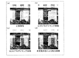
図14は、本開示の第1の実施の形態における撮像システムに用いられるカラー画像生成回路203が生成したRチャネル画像の一例である。図15は、本開示の第1の実施の形態における撮像システムに用いられるカラー画像生成回路203が生成したGチャネル画像の一例である。図16は、本開示の第1の実施の形態における撮像システムに用いられるカラー画像生成回路203が生成したBチャネル画像の一例である。図14から図16において、それぞれ、(a)は3板式カメラで撮影した正解カラー画像、(b)は一般的なデモザイキング手法である特許文献1に記載のAdaptive Color Plane Interpolation法(ACPI法)によるデモザイキング画像、(c)は非特許文献5に記載のMinimized−Laplacian Residual Interpolation法(MLRI法)によるデモザイキング画像及び(d)は第1の実施の形態における撮像システムに用いられるカラー画像生成回路203が生成した復元画像を示している。
FIG. 14 is an example of an R channel image generated by the color
以下では例として図14を参照して説明するが、図15および図16にも同様の説明が適用され得る。 Hereinafter, an example will be described with reference to FIG. 14, but the same description can be applied to FIGS. 15 and 16.
図14(a)の画像の中央部には、格子状のパターンを有する窓が示されている。図14(b)及び(c)の各画像は、図20に示す従来のベイヤー配列のカラーフィルタを用いて撮影された画像である。本発明者は検証を行い、図14(b)に示すACPIによるデモザイキング画像では、エッジ近傍に偽色が存在することを確認した。具体的には、本発明者は、窓のエッジ部分に実際に偽色の存在を確認した。本発明者は、図14(d)に示す本実施形態による復元画像にはこのような偽色が存在していないことも確認した。 A window having a lattice pattern is shown at the center of the image in FIG. Each of the images in FIGS. 14B and 14C is an image photographed using the conventional Bayer color filter shown in FIG. The inventor has verified and confirmed that a false color exists in the vicinity of the edge in the demosaicing image by ACPI shown in FIG. Specifically, the present inventor has actually confirmed the presence of a false color at the edge portion of the window. The inventor has also confirmed that such a false color does not exist in the restored image according to this embodiment shown in FIG.
また、図14(c)に示すMLRI法によるデモザイキング画像では、窓の格子状のパターンなどに対応する高周波成分が復元できていない。一方、図14(d)に示す本実施形態による復元画像では、従来技術に比べ、偽色もなく、高周波成分まで復元できていることがわかる。 Further, in the demosaicing image by the MLRI method shown in FIG. 14C, the high frequency component corresponding to the lattice pattern of the window cannot be restored. On the other hand, it can be seen that the restored image according to the present embodiment shown in FIG. 14 (d) has been restored to the high frequency component without false color compared to the prior art.
図17は、全ての色を含むカラー画像の一例である。図17は、当該カラー画像の輝度値を利用して示されている。窓の格子状のパターンを一見すると明らかなように、本実施の形態による復元画像が正解画像に最も近いと言える。 FIG. 17 is an example of a color image including all colors. FIG. 17 is shown using the luminance value of the color image. As can be seen from a glance at the grid pattern of the window, it can be said that the restored image according to the present embodiment is closest to the correct image.
(第2の実施の形態)
次に、図18を参照して第2の実施の形態について説明する。図18は、本開示の第2の実施の形態における撮像装置1を示す概略ブロック図である。第2の実施の形態の撮像装置1において、第1の実施の形態と異なり、フィルターユニット102は、0mmの厚みの領域を有する複数のカラーフィルタ(102aから102c)及び、空間光変調器112を備えている。ここで、空間光変調器112は、空間的・時間的に光透過率特性を変調させる光学素子のことである。空間光変調器112の光透過率特性は、撮像素子103の画素単位にランダムに異ならせることが可能である。尚、図18において図2と同一の構成要素については、同一の符号を付し、説明を省略する。
(Second Embodiment)
Next, a second embodiment will be described with reference to FIG. FIG. 18 is a schematic block diagram illustrating the
図18に示すように、撮像素子103と複数のカラーフィルタ(102aから102c)との間に、複数のカラーフィルタ(102aから102c)を透過した光の明度を変調させる空間光変調器112を設けている。また、カラーフィルタ102aから102cの各々には、撮像素子103の画素単位でカラーフィルタの厚みが0mmである箇所が存在する。また、カラーフィルタ102aから102cの各々の厚みは、前記カラーフィルタの厚みが0mmである箇所を除くと、一定である。
As shown in FIG. 18, a spatial light modulator 112 that modulates the lightness of light transmitted through the plurality of color filters (102a to 102c) is provided between the
ここで、各画素に対応する位置における各カラーフィルタの厚みが0mmであるかどうかによって、決まった値をとる関数Mを次のように定義する。画素(u,v)に対応する位置において、カラーフィルタ102aの厚みが0mmでない場合はM1(u,v)=1、カラーフィルタ102aの厚みが0mmである場合はM1(u,v)=0とする。同様に、画素(u,v)に対応する位置において、カラーフィルタ102bの厚みが0mmでない場合はM2(u,v)=1、カラーフィルタ2の厚みが0mmである場合はM2(u,v)=0とする。画素(u,v)に対応する位置において、カラーフィルタ102cの厚みが0mmでない場合はM3(u,v)=1、カラーフィルタ3の厚みが0mmである場合はM3(u,v)=0とする。さらに、画素(u,v)に対応する位置における空間光変調器112の光透過率特性をS(u,v)とする。この場合、画素位置(u,v)に対応する位置における複数のカラーフィルタ(102aから102c)及び空間光変調器112の全体の光透過率特性、即ち、フィルターユニット102全体の光透過率特性x(λ, u,v)は、次式で表現される。
ただし、Pは、各カラーフィルタの厚みが0mmであるかどうかによって光透過率特性を決定する関数であり、次式で表現される。
数19及び数20に示すように、複数のカラーフィルタ(102aから102c)の波長単位の光透過率特性C1(λ)、C2(λ)及びC3(λ)を画素位置に依存しないようにして複数のカラーフィルタ(102aから102c)の構造を簡素化したとしても、空間光変調器112を介在させて、フィルターユニット102全体の光透過率特性x(λ, u,v)を、撮像素子103の画素単位にランダムに異ならせることができる。そのため、複数のカラーフィルタ(102aから102c)の構造を簡素化することにより、前記各画素に対応する光透過率特性のパターン数が制限される場合でも、空間光変調器112を用いることで、前記各画素に対応する光透過率特性のパターンを増加させることができる。例えば、上記のように、3つのカラーフィルタを利用すると、複数のカラーフィルタ(102aから102c)の全体の光透過率特性を8種類作り出すことができる。これに、空間光変調器112を加えることで、上述の8種類をさらに増大させることができる。その結果、複数のカラーフィルタ(102aから102c)の構造を簡素化した場合でも、復元画像の再現品質を向上させることができる。
As shown in
(第3の実施の形態)
次に、図19を参照して第3の実施の形態について説明する。図19は、本開示の第3の実施の形態における撮像装置1を示す概略ブロック図である。第3の実施の形態の撮像装置1において、第1の実施の形態と異なり、フィルターユニット102は、複数のカラーフィルタ(102aから102c)以外にも空間光変調器112を備えている。尚、図19において図2および図18と同一の構成要素については、同一の符号を付し、説明を省略する。
(Third embodiment)
Next, a third embodiment will be described with reference to FIG. FIG. 19 is a schematic block diagram illustrating the
図19に示すように、撮像素子103と複数のカラーフィルタ(102aから102c)との間に、複数のカラーフィルタ(102aから102c)を透過した光の明度を変調させる空間光変調器112を設けている。この場合、画素位置(u,v)に対応する位置における光透過率特性x(λ, u,v)は、次式で表現される。
数21において、複数のカラーフィルタ(102aから102c)の全体の光透過率特性、即ち、Φ(C1(λ),T1(u,v))・Φ(C2(λ),T2(u,v))・Φ(C3(λ),T3(u,v))は、画素単位にランダムに異なる。さらに、空間光変調器112の光透過率特性S(u,v)は画素単位にランダムに異なる。この結果、複数のカラーフィルタ(102aから102c)及び空間光変調器112の全体の光透過率特性、即ち、フィルターユニット102全体の光透過率特性x(λ, u,v)を、相乗的にランダムな状態で画素単位に相互に異ならせることができる。加えて、複数のカラーフィルタ(102aから102c)の波長単位の光透過率特性Φ(C1(λ),T1(u,v))、Φ(C2(λ),T2(u,v))及びΦ(C3(λ),T3(u,v))は、画素単位にランダムに異なる。このように、画素単位及び波長単位で相乗的にランダムに異ならせたことにより、画像生成装置2において圧縮センシング技術を用いてカラー画像を生成する際に元のカラー画像をより正確に再現できる。
In Equation 21, the overall light transmittance characteristics of the plurality of color filters (102a to 102c), that is, Φ (C1 (λ), T1 (u, v)) · Φ (C2 (λ), T2 (u, v) )) · Φ (C3 (λ), T3 (u, v)) is randomly different for each pixel. Further, the light transmittance characteristic S (u, v) of the spatial light modulator 112 is randomly different for each pixel. As a result, the overall light transmittance characteristics of the plurality of color filters (102a to 102c) and the spatial light modulator 112, that is, the light transmittance characteristics x (λ, u, v) of the
さらに、複数の画像を撮像する場合、撮像フレーム毎に空間光変調器112の光透過率特性S(u,v)を撮像素子103の画素単位で変化させることによって、フィルターユニット102全体の光透過率特性x(λ, u,v)を撮像フレーム単位でもランダムに異ならせることができる。これにより、ランダム性がさらに高まる結果、前記画像生成装置において圧縮センシング技術を用いてカラー画像を生成する際に元のカラー画像をより一層正確に再現できる。
Further, when a plurality of images are captured, the light transmittance of the
以上、一つまたは複数の態様に係る撮像装置システムについて、実施の形態に基づいて説明したが、本開示は、この実施の形態に限定されるものではない。本開示の主旨を逸脱しない限り、当業者が思いつく各種変形を本実施の形態に施したものや、異なる実施の形態における構成要素を組み合わせて構築される形態も、一つまたは複数の態様の範囲内に含まれてもよい。 As described above, the imaging apparatus system according to one or more aspects has been described based on the embodiment, but the present disclosure is not limited to this embodiment. Unless the scope of the present disclosure is deviated, various modifications conceived by those skilled in the art have been made in the present embodiment, and forms constructed by combining components in different embodiments are also within the scope of one or more aspects. May be included.
(本開示の実施の形態の概要)
本開示の一態様の撮像装置は、
被写体からの光を集光する結像光学系と、
複数の画素を有し、前記集光された光を受光して電気信号に変換する撮像素子と、
前記結像光学系及び前記撮像素子の間に配置され、異なる第一群の光透過率特性を有する複数のカラーフィルタを含むフィルターユニットと、
前記電気信号を符号化する送信データ圧縮回路と、を備え、
前記フィルターユニット全体の光透過率特性は、前記撮像素子の画素単位でランダムに異なり、
前記送信データ圧縮回路は、前記撮像素子の前記複数の画素の中の各画素に対応する前記フィルターユニット全体の光透過率特性の、各画素間で共通な波長特性に対する割合の逆数を用いて、前記各画素の電気信号を重み付けして符号化する、ものである。
(Outline of Embodiment of the Present Disclosure)
An imaging device according to one embodiment of the present disclosure is provided.
An imaging optical system that collects light from the subject;
An image sensor having a plurality of pixels, receiving the collected light and converting it into an electrical signal;
A filter unit including a plurality of color filters disposed between the imaging optical system and the imaging device and having different first group light transmittance characteristics;
A transmission data compression circuit for encoding the electrical signal,
The light transmittance characteristic of the entire filter unit is randomly different for each pixel of the image sensor,
The transmission data compression circuit uses the reciprocal of the ratio of the light transmittance characteristic of the entire filter unit corresponding to each pixel of the plurality of pixels of the image sensor to the wavelength characteristic common to the pixels, The electrical signal of each pixel is weighted and encoded.
本開示の一態様によると、異なる光透過率特性を有する複数のカラーフィルタを含むフィルターユニットを設ける。従来のベイヤー配列などの画素毎に相互に異なる単一のカラーフィルタを使用した場合は、カラー画像を再現する際に取得していない色の情報を別の色情報からデータ補間するため、これに起因して偽色が発生する。一方で、本態様では、被写体からすべての色情報を含んだ光を受光するので、解像度の低下を防止しつつ偽色の発生を防止できる。 According to one aspect of the present disclosure, a filter unit including a plurality of color filters having different light transmittance characteristics is provided. When using a single different color filter for each pixel such as a conventional Bayer array, color information not acquired when reproducing a color image is interpolated from other color information. This causes false color. On the other hand, in this aspect, since light including all color information is received from the subject, generation of false colors can be prevented while preventing a decrease in resolution.
また、前記フィルターユニット全体の光透過率特性は、前記撮像素子の画素単位でランダムに異なる。これは、前記フィルターユニットに含まれている複数のカラーフィルタの波長単位の光透過率特性を、前記撮像素子の前記複数の画素の各々に対応する位置においてランダムに異ならせているからである。この結果、前記複数のカラーフィルタを含む前記フィルターユニット全体の光透過率特性は、画素単位だけでなく波長単位でもランダムに異なることとなる。これにより、前記被写体からの光の光透過率を、画素単位及び波長単位で相乗的にランダムに異ならせている。このようにランダム性を高めているのは、本態様の撮像装置から前記符号化された電気信号を入力した画像生成装置において、前記ランダム性が高いほど元のカラー画像をより正確に再現することが可能となるからである。具体的には、前記画像生成装置において圧縮センシング技術を用いてカラー画像を生成するが、圧縮センシング技術では、データをサンプリングする際によりランダムな状態でサンプリングすることで、復元したデータと元のデータとの差異がより小さくなる。この点に鑑みて、上記のように前記ランダム性を画素単位及び波長単位で相乗的に高めている。 Further, the light transmittance characteristics of the entire filter unit are randomly different for each pixel of the image sensor. This is because the light transmittance characteristics in units of wavelengths of the plurality of color filters included in the filter unit are randomly changed at positions corresponding to the plurality of pixels of the image sensor. As a result, the light transmittance characteristics of the entire filter unit including the plurality of color filters are randomly different not only in pixel units but also in wavelength units. As a result, the light transmittance of the light from the subject is varied in a synergistic and random manner in units of pixels and wavelengths. The reason why the randomness is increased in this way is that the higher the randomness is, the more accurately the original color image is reproduced in the image generation apparatus that receives the encoded electrical signal from the imaging apparatus of this aspect. This is because it becomes possible. Specifically, a color image is generated by using the compressed sensing technology in the image generation device. In the compressed sensing technology, the restored data and the original data are sampled by sampling in a more random state when sampling the data. And the difference is smaller. In view of this point, the randomness is synergistically improved in units of pixels and wavelengths as described above.
さらに、前記送信データ圧縮回路は、前記撮像素子の前記複数の画素の中の各画素に対応する前記フィルターユニット全体の光透過率特性の、各画素間で共通な波長特性に対する割合の逆数を用いて、前記各画素の電気信号を重み付けして符号化する。これにより、前記重み付けされた電気信号は、前記各画素間で共通な波長特性を有するカラーフィルタを使用して得られる電気信号と近似する。このように、前記各画素に対応する前記重み付けした電気信号は、いずれも前記各画素間で共通な波長特性を基準とした値である。このため、光透過率特性が等しい画素間で電気信号の差分を計算し、圧縮率を高める従来技術と同程度の圧縮率を実現できる。これにより、たとえ、カラー画像の再現性を高めるために、画素単位及び波長単位の光透過率特性をランダムに異ならせたフィルターユニットを使用して前記電気信号を取得した場合であっても、解像度の低下及び偽色の発生を防止しつつ、一つの画素に対して赤(R)、緑(G)又は青(B)のいずれか一つの波長域の光を透過させる単一のカラーフィルタを使用する従来技術と同程度にまで伝送圧縮効率を向上させることができる。 Further, the transmission data compression circuit uses a reciprocal of a ratio of a light transmittance characteristic of the entire filter unit corresponding to each pixel of the plurality of pixels of the image sensor to a wavelength characteristic common to the pixels. Thus, the electric signals of the respective pixels are weighted and encoded. Thereby, the weighted electrical signal approximates an electrical signal obtained using a color filter having a wavelength characteristic common to the pixels. As described above, the weighted electrical signals corresponding to the respective pixels are values based on wavelength characteristics common to the respective pixels. For this reason, it is possible to realize a compression rate comparable to that of the conventional technique for calculating the difference of the electric signal between pixels having the same light transmittance characteristics and increasing the compression rate. Thereby, in order to improve the reproducibility of the color image, even when the electrical signal is acquired using a filter unit in which the light transmittance characteristics of the pixel unit and the wavelength unit are randomly changed, the resolution is improved. A single color filter that transmits light in any one wavelength band of red (R), green (G), and blue (B) to one pixel while preventing a decrease in color and generation of false color Transmission compression efficiency can be improved to the same extent as the conventional technology used.
一方で、本態様の撮像装置から前記符号化された電気信号を入力した画像生成装置において、前記撮像素子の前記複数の画素の中の各画素に対応する前記フィルターユニット全体の光透過率特性の、各画素間で共通な波長特性に対する割合の逆数を入手していれば、前記符号化された電気信号を元の重み付けされていない電気信号に再現できる。その結果、たとえ、カラー画像の再現性を高めるために、画素単位及び波長単位の光透過率特性をランダムに異ならせたフィルターユニットを使用して前記電気信号を取得した場合であっても、解像度の低下及び偽色の発生を防止しつつ、一つの画素に対して赤(R)、緑(G)又は青(B)のいずれか一つの波長域の光を透過させる単一のカラーフィルタを使用する従来技術と同程度にまで伝送圧縮効率を向上させることができる。 On the other hand, in the image generation device that receives the encoded electrical signal from the imaging device of this aspect, the light transmittance characteristics of the entire filter unit corresponding to each pixel of the plurality of pixels of the imaging device. If the reciprocal of the ratio with respect to the wavelength characteristic common to the respective pixels is obtained, the encoded electric signal can be reproduced as the original unweighted electric signal. As a result, in order to improve the reproducibility of the color image, even when the electrical signal is acquired using a filter unit in which the light transmittance characteristics of the pixel unit and the wavelength unit are randomly changed, the resolution is improved. A single color filter that transmits light in any one wavelength band of red (R), green (G), and blue (B) to one pixel while preventing a decrease in color and generation of false color Transmission compression efficiency can be improved to the same extent as the conventional technology used.
また、上記態様において、例えば、前記フィルターユニット全体の光透過率特性は、前記第一群とは異なる第二群の異なる光透過率特性の線形和で表現されるものであってもよい。 In the above aspect, for example, the light transmittance characteristics of the entire filter unit may be expressed by a linear sum of different light transmittance characteristics of a second group different from the first group.
上記態様によると、前記フィルターユニットとして、前記フィルターユニット全体の光透過率特性は、前記第一群とは異なる第二群の異なる光透過率特性の線形和で表現されるものを用いることができる。ここで、第二群の異なる光透過率特性は、再現するカラー画像それぞれの光透過率特性である。これにより、たとえ、カラー画像の再現性を高めるために、画素単位で光透過率特性をランダムに異ならせたフィルターユニットを使用して前記電気信号を取得した場合であっても、解像度の低下及び偽色の発生を防止しつつ、一つの画素に対して赤(R)、緑(G)又は青(B)のいずれか一つの波長域の光を透過させる単一のカラーフィルタを使用する従来技術と同程度にまで伝送圧縮効率を向上させることができる。 According to the above aspect, as the filter unit, the light transmittance characteristic of the entire filter unit can be expressed by a linear sum of different light transmittance characteristics of a second group different from the first group. . Here, the different light transmittance characteristics of the second group are the light transmittance characteristics of the respective color images to be reproduced. Thereby, in order to improve the reproducibility of a color image, even when the electrical signal is acquired using a filter unit having light transmittance characteristics that are randomly changed for each pixel, the resolution is reduced and Conventionally, a single color filter that transmits light in any one wavelength range of red (R), green (G), and blue (B) to one pixel while preventing generation of a false color is used. Transmission compression efficiency can be improved to the same extent as technology.
本開示の別の一態様の撮像装置は、
被写体からの光を集光する結像光学系と、
複数の画素を有し、前記集光された光を受光して電気信号に変換する撮像素子と、
前記結像光学系及び前記撮像素子の間に配置され、異なる光透過率特性を有する複数のカラーフィルタと、
前記電気信号を符号化する送信データ圧縮回路と、を備え、
前記複数のカラーフィルタの全体の光透過率特性は、前記撮像素子の画素単位でランダムに異なり、
前記送信データ圧縮回路は、前記撮像素子の前記複数の画素の中の各画素に対応する前記複数のカラーフィルタの全体の光透過率特性の、各画素間で共通な波長特性に対する割合の逆数を用いて、前記各画素の電気信号を重み付けして符号化する、ものである。
An imaging device according to another aspect of the present disclosure is provided.
An imaging optical system that collects light from the subject;
An image sensor having a plurality of pixels, receiving the collected light and converting it into an electrical signal;
A plurality of color filters disposed between the imaging optical system and the imaging device and having different light transmittance characteristics;
A transmission data compression circuit for encoding the electrical signal,
The overall light transmittance characteristics of the plurality of color filters are randomly different in pixel units of the image sensor,
The transmission data compression circuit calculates a reciprocal of a ratio of a total light transmittance characteristic of the plurality of color filters corresponding to each pixel of the plurality of pixels of the image sensor to a wavelength characteristic common to the pixels. The electrical signal of each pixel is weighted and encoded.
本開示の一態様によると、異なる光透過率特性を有する複数のカラーフィルタを設ける。従来のベイヤー配列などの画素毎に相互に異なる単一のカラーフィルタを使用した場合は、カラー画像を再現する際に取得していない色の情報を別の色情報からデータ補間するため、これに起因して偽色が発生する。一方で、本態様では、被写体からすべての色情報を含んだ光を受光するので、解像度の低下を防止しつつ偽色の発生を防止できる。 According to one aspect of the present disclosure, a plurality of color filters having different light transmittance characteristics are provided. When using a single different color filter for each pixel such as a conventional Bayer array, color information not acquired when reproducing a color image is interpolated from other color information. This causes false color. On the other hand, in this aspect, since light including all color information is received from the subject, generation of false colors can be prevented while preventing a decrease in resolution.
また、前記複数のカラーフィルタの全体の光透過率特性は、前記撮像素子の画素単位でランダムに異なる。これは、前記複数のカラーフィルタの波長単位の光透過率特性を前記撮像素子の前記複数の画素の各々に対応する位置においてランダムに異ならせているからである。この結果、前記複数のカラーフィルタの全体の光透過率特性は、画素単位だけでなく波長単位でもランダムに異なることとなる。これにより、前記被写体からの光の光透過率特性を、画素単位及び波長単位で相乗的にランダムに異ならせている。このようにランダム性を高めているのは、本態様の撮像装置から前記符号化された電気信号を入力した画像生成装置において、前記ランダム性が高いほど元のカラー画像をより正確に再現することが可能となるからである。具体的には、前記画像生成装置において圧縮センシング技術を用いてカラー画像を生成するが、圧縮センシング技術では、データをサンプリングする際によりランダムな状態でサンプリングすることで、復元したデータと元のデータとの差異がより小さくなる。この点に鑑みて、上記のように前記ランダム性を画素単位及び波長単位で相乗的に高めている。 Further, the overall light transmittance characteristics of the plurality of color filters are randomly different for each pixel of the image sensor. This is because the light transmittance characteristics in wavelength units of the plurality of color filters are randomly varied at positions corresponding to the plurality of pixels of the image sensor. As a result, the overall light transmittance characteristics of the plurality of color filters are randomly different not only in pixel units but also in wavelength units. As a result, the light transmittance characteristics of light from the subject are changed synergistically and randomly at the pixel unit and the wavelength unit. The reason why the randomness is increased in this way is that the higher the randomness is, the more accurately the original color image is reproduced in the image generation apparatus that receives the encoded electrical signal from the imaging apparatus of this aspect. This is because it becomes possible. Specifically, a color image is generated by using the compressed sensing technology in the image generation device. In the compressed sensing technology, the restored data and the original data are sampled by sampling in a more random state when sampling the data. And the difference is smaller. In view of this point, the randomness is synergistically improved in units of pixels and wavelengths as described above.
さらに、前記送信データ圧縮回路は、前記撮像素子の前記複数の画素の中の各画素に対応する前記複数のカラーフィルタの全体の光透過率特性の、各画素間で共通な波長特性に対する割合の逆数を用いて、前記各画素の電気信号を重み付けして符号化する。これにより、前記重み付けされた電気信号は、前記各画素間で共通な波長特性を有するカラーフィルタを使用して得られる電気信号と近似する。このように、前記各画素に対応する前記重み付けした電気信号は、いずれも前記各画素間で共通な波長特性を基準とした値である。このため、光透過率特性が等しい画素間で電気信号の差分を計算し、圧縮率を高める従来技術と同程度の圧縮率を実現できる。これにより、たとえ、カラー画像の再現性を高めるために、画素単位で光透過率特性をランダムに異ならせた複数のカラーフィルタを使用して前記電気信号を取得した場合であっても、解像度の低下及び偽色の発生を防止しつつ、一つの画素に対して赤(R)、緑(G)又は青(B)のいずれか一つの波長域の光を透過させる単一のカラーフィルタを使用する従来技術と同程度にまで伝送圧縮効率を向上させることができる。 Further, the transmission data compression circuit is configured to obtain a ratio of a total light transmittance characteristic of the plurality of color filters corresponding to each pixel of the plurality of pixels of the image sensor to a wavelength characteristic common to the pixels. Using the reciprocal, the electric signal of each pixel is weighted and encoded. Thereby, the weighted electrical signal approximates an electrical signal obtained using a color filter having a wavelength characteristic common to the pixels. As described above, the weighted electrical signals corresponding to the respective pixels are values based on wavelength characteristics common to the respective pixels. For this reason, it is possible to realize a compression rate comparable to that of the conventional technique for calculating the difference of the electric signal between pixels having the same light transmittance characteristics and increasing the compression rate. Thereby, in order to improve the reproducibility of a color image, even when the electrical signal is acquired using a plurality of color filters whose light transmittance characteristics are randomly changed for each pixel, the resolution of Uses a single color filter that transmits light in one of the red (R), green (G), and blue (B) wavelengths to one pixel while preventing deterioration and false color generation The transmission compression efficiency can be improved to the same extent as in the prior art.
一方で、本態様の撮像装置から前記符号化された電気信号を入力した画像生成装置において、前記撮像素子の前記複数の画素の中の各画素に対応する前記複数のカラーフィルタの全体の光透過率特性の、各画素間で共通な波長特性に対する割合の逆数を入手していれば、前記符号化された電気信号を元の重み付けされていない電気信号に再現できる。その結果、たとえ、カラー画像の再現性を高めるために、画素単位で光透過率特性をランダムに異ならせた複数のカラーフィルタを使用して前記電気信号を取得した場合であっても、解像度の低下及び偽色の発生を防止しつつ、一つの画素に対して赤(R)、緑(G)又は青(B)のいずれか一つの波長域の光を透過させる単一のカラーフィルタを使用する従来技術と同程度にまで伝送圧縮効率を向上させることができる。 On the other hand, in the image generation device that receives the encoded electrical signal from the imaging device of this aspect, the entire light transmission of the plurality of color filters corresponding to each pixel of the plurality of pixels of the imaging device. If the reciprocal of the ratio of the rate characteristic to the wavelength characteristic common to each pixel is obtained, the encoded electric signal can be reproduced as the original unweighted electric signal. As a result, in order to improve the reproducibility of a color image, even when the electrical signal is acquired using a plurality of color filters whose light transmittance characteristics are randomly changed for each pixel, the resolution of Uses a single color filter that transmits light in one of the red (R), green (G), and blue (B) wavelengths to one pixel while preventing deterioration and false color generation The transmission compression efficiency can be improved to the same extent as in the prior art.
また、上記態様において、例えば、前記複数のカラーフィルタの波長単位の光透過率特性は、前記撮像素子の前記複数の画素の各々に対応する位置においてランダムに異なってもよい。 In the above aspect, for example, the light transmittance characteristics in units of wavelengths of the plurality of color filters may be randomly different at positions corresponding to the plurality of pixels of the image sensor.
上記態様によると、前記複数のカラーフィルタの全体の光透過率特性は、前記撮像素子の画素単位でランダムに異なる。また、前記複数のカラーフィルタの波長単位の光透過率特性は、前記撮像素子の前記複数の画素の各々に対応する位置においてランダムに異なる。これにより、前記被写体からの光の光透過率特性を、画素単位及び波長単位で相乗的にランダムに異ならせている。このため、本態様の撮像装置から前記符号化された電気信号を入力した画像生成装置において、圧縮センシングを用いて元のカラー画像を再現する際に、元のカラー画像をより正確に再現することが可能となる。 According to the above aspect, the overall light transmittance characteristics of the plurality of color filters are randomly different for each pixel of the image sensor. Further, the light transmittance characteristics of the plurality of color filters in units of wavelength are randomly different at positions corresponding to the plurality of pixels of the image sensor. As a result, the light transmittance characteristics of light from the subject are changed synergistically and randomly at the pixel unit and the wavelength unit. For this reason, when an original color image is reproduced using compressed sensing in an image generation apparatus that receives the encoded electrical signal from the imaging apparatus according to this aspect, the original color image is more accurately reproduced. Is possible.
また、上記態様において、例えば、前記各画素間で共通な波長特性は、赤(R)、緑(G)及び青(B)に対応する全波長域において光透過率が等しいものであってもよい。 In the above aspect, for example, the wavelength characteristics common to the respective pixels may have the same light transmittance in all wavelength ranges corresponding to red (R), green (G), and blue (B). Good.
上記態様によると、前記波長特性は、赤(R)、緑(G)及び青(B)の各成分の光透過率が均等な光透過率特性である。前記各画素間で共通な波長特性を基準とした前記重み付けにより、前記電気信号は、赤(R)、緑(G)及び青(B)に対応する全波長域において光透過率が等しい光透過率特性を基準とした値に変換される。即ち、前記重み付けされた電気信号は、赤(R)、緑(G)及び青(B)に対応する全波長域において光透過率が等しい光透過率特性を有するカラーフィルタを使用して得られる電気信号と近似する。これにより、解像度の低下及び偽色の発生を防止しつつ、一つの画素に対して赤(R)、緑(G)又は青(B)のいずれか一つの波長域の光を透過させる単一のカラーフィルタを使用する従来技術と同程度にまで伝送圧縮効率を向上させることができる。 According to the said aspect, the said wavelength characteristic is a light transmittance characteristic with the uniform light transmittance of each component of red (R), green (G), and blue (B). Due to the weighting based on the wavelength characteristic common to the pixels, the electrical signal has the same light transmittance in all wavelength ranges corresponding to red (R), green (G), and blue (B). Converted to a value based on rate characteristics. That is, the weighted electrical signal is obtained using a color filter having a light transmittance characteristic that has the same light transmittance in all wavelength ranges corresponding to red (R), green (G), and blue (B). Approximate electrical signal. Thus, a single pixel that transmits light in any one wavelength band of red (R), green (G), and blue (B) to one pixel while preventing a decrease in resolution and generation of false color. The transmission compression efficiency can be improved to the same extent as in the prior art using the color filter.
また、上記態様において、例えば、前記各画素間で共通な波長特性は、比視感度を示すものであってもよい。 In the above aspect, for example, the wavelength characteristic common to the respective pixels may indicate relative luminous sensitivity.
ここで、比視感度とは、人間の目が光の波長ごとの明るさを感じる強さを数値で表したものである。 Here, the relative luminous sensitivity is a numerical value representing the strength with which the human eye feels the brightness of each wavelength of light.
上記態様によると、前記各画素間で共通な波長特性を基準とした前記重み付けにより、前記電気信号は、比視感度を基準とした値に変換される。即ち、前記重み付けされた電気信号は、比視感度を示す波長特性を有するカラーフィルタを使用して得られる電気信号と近似する。これにより、解像度の低下及び偽色の発生を防止しつつ、一つの画素に対して赤(R)、緑(G)又は青(B)のいずれか一つの波長域の光を透過させる単一のカラーフィルタを使用する従来技術と同程度にまで伝送圧縮効率を向上させることができる。 According to the above aspect, the electrical signal is converted into a value based on relative luminous sensitivity by the weighting based on a wavelength characteristic common to the pixels. In other words, the weighted electric signal approximates an electric signal obtained using a color filter having a wavelength characteristic indicating specific visibility. Thus, a single pixel that transmits light in any one wavelength band of red (R), green (G), and blue (B) to one pixel while preventing a decrease in resolution and generation of false color. The transmission compression efficiency can be improved to the same extent as in the prior art using the color filter.
また、上記態様において、例えば、前記各画素間で共通な波長特性は、比視感度に近似したものであってもよい。 In the above aspect, for example, the wavelength characteristic common to the pixels may be approximated to the relative luminous sensitivity.
上記態様によると、前記比視感度を示す波長特性の代わりに前記比視感度に近似した波長特性を、前記各画素間で共通な波長特性として用いることができる。これにより、前記比視感度を示す波長特性に厳密に拘る必要がなくなり、前記各画素間で共通な波長特性の選択肢を増やすことができる。 According to the above aspect, a wavelength characteristic approximate to the specific luminous sensitivity can be used as a wavelength characteristic common to the pixels instead of the wavelength characteristic indicating the specific luminous efficiency. Accordingly, it is not necessary to strictly adhere to the wavelength characteristic indicating the relative luminous sensitivity, and it is possible to increase the choices of wavelength characteristics common to the respective pixels.
また、上記態様において、例えば、前記各画素間で共通な波長特性は、赤(R)及び青(B)に対応する波長域においては光透過率が0であり、緑(G)に対応する波長域のみ光透過率が0超のものであってもよい。 In the above aspect, for example, the wavelength characteristic common to the respective pixels has a light transmittance of 0 in the wavelength range corresponding to red (R) and blue (B), and corresponds to green (G). Only in the wavelength region, the light transmittance may be greater than zero.
ここで、人間の目には、赤(R)、緑(G)及び緑(G)の内、緑(G)に対する感度が最も高い。 Here, human eyes have the highest sensitivity to green (G) among red (R), green (G), and green (G).
上記態様によると、赤(R)及び青(B)に対応する波長域においては光透過率が0であり、緑(G)に対応する波長域においては光透過率が0超である光透過率特性を前記各画素間で共通な波長特性として用いる。その結果、前記各画素間で共通な波長特性を基準とした前記重み付けにより、前記電気信号は、緑(G)の波長域を基準とした値に変換される。即ち、前記重み付けされた電気信号は、赤(R)及び青(B)に対応する波長域においては光透過率が0であり、緑(G)に対応する波長域のみ光透過率が0超である光透過率特性を有するカラーフィルタを使用して得られる電気信号と近似する。これにより、解像度の低下及び偽色の発生を防止しつつ、一つの画素に対して赤(R)、緑(G)又は青(B)のいずれか一つの波長域の光を透過させる単一のカラーフィルタを使用する従来技術と同程度にまで伝送圧縮効率を向上させることができる。 According to the above aspect, the light transmittance is 0 in the wavelength region corresponding to red (R) and blue (B), and the light transmittance is more than 0 in the wavelength region corresponding to green (G). The rate characteristic is used as a wavelength characteristic common to the pixels. As a result, the electrical signal is converted into a value based on the green (G) wavelength region by the weighting based on the wavelength characteristic common to the pixels. That is, the weighted electrical signal has a light transmittance of 0 in the wavelength range corresponding to red (R) and blue (B), and has a light transmittance of more than 0 only in the wavelength range corresponding to green (G). It approximates to an electrical signal obtained using a color filter having a light transmittance characteristic. Thus, a single pixel that transmits light in any one wavelength band of red (R), green (G), and blue (B) to one pixel while preventing a decrease in resolution and generation of false color. The transmission compression efficiency can be improved to the same extent as in the prior art using the color filter.
また、上記態様において、例えば、前記各画素間で共通な波長特性は、各画素間で共通なレッド特性とブルー特性との差分特性を示すものであってもよい。 In the above aspect, for example, the wavelength characteristic common to the pixels may indicate a difference characteristic between a red characteristic and a blue characteristic common to the pixels.
上記態様によると、前記波長特性を基準とした前記重み付けにより、前記電気信号は、レッド特性とブルー特性との差分特性、即ち、色差を基準とした値に変換される。即ち、前記重み付けされた電気信号は、色差を示す波長特性を有するカラーフィルタを使用して得られる電気信号と近似する。これにより、解像度の低下及び偽色の発生を防止しつつ、一つの画素に対して赤(R)、緑(G)又は青(B)のいずれか一つの波長域の光を透過させる単一のカラーフィルタを使用する従来技術と同程度にまで伝送圧縮効率を向上させることができる。 According to the above aspect, the electrical signal is converted into a difference characteristic between the red characteristic and the blue characteristic, that is, a value based on the color difference, by the weighting based on the wavelength characteristic. That is, the weighted electric signal approximates an electric signal obtained using a color filter having a wavelength characteristic indicating a color difference. Thus, a single pixel that transmits light in any one wavelength band of red (R), green (G), and blue (B) to one pixel while preventing a decrease in resolution and generation of false color. The transmission compression efficiency can be improved to the same extent as in the prior art using the color filter.
また、上記態様において、例えば、前記各画素の符号化された電気信号を、前記各画素の符号化された電気信号を復号化する画像生成装置に出力する送信回路を備えてもよい。 In the above aspect, for example, a transmission circuit may be provided that outputs the encoded electrical signal of each pixel to an image generation device that decodes the encoded electrical signal of each pixel.
上記態様によると、前記撮像装置は、前記送信回路を介して前記画像生成装置に、前記各画素の符号化された電気信号を出力できる。 According to the above aspect, the imaging device can output the encoded electrical signal of each pixel to the image generation device via the transmission circuit.
また、上記態様において、例えば、前記送信回路は、前記各画素に対応する前記複数のカラーフィルタの全体の光透過率特性の、前記各画素間で共通な波長特性に対する割合の逆数を示す変調情報を、前記画像生成装置に出力するようにしてもよい。 Further, in the above aspect, for example, the transmission circuit includes modulation information indicating an inverse number of a ratio of the overall light transmittance characteristics of the plurality of color filters corresponding to the pixels to the wavelength characteristics common to the pixels. May be output to the image generating apparatus.
上記態様によると、前記画像生成装置は、本態様の撮像装置から前記各画素に対応する前記複数のカラーフィルタの全体の光透過率特性の、前記各画素間で共通な波長特性に対する割合の逆数を示す変調情報を入手できる。そのため、前記画像生成装置は、前記符号化された各画素の電気信号になされた重み付けを再現できる。 According to the above aspect, the image generation apparatus is the reciprocal of the ratio of the overall light transmittance characteristics of the plurality of color filters corresponding to the pixels from the imaging apparatus of the aspect to the wavelength characteristics common to the pixels. Can be obtained. Therefore, the image generation device can reproduce the weighting applied to the encoded electric signal of each pixel.
また、上記態様において、例えば、前記送信回路は、前記画像生成装置に接続される1回目の通信では、前記変調情報と前記1回目の通信に対応する各画素の符号化された電気信号とを出力し、2回目以降の通信では、前記変調情報を出力することなく前記2回目以降の各通信に対応する各画素の符号化された電気信号を出力するようにしてもよい。 In the above aspect, for example, in the first communication connected to the image generation device, the transmission circuit transmits the modulation information and the encoded electric signal of each pixel corresponding to the first communication. In the second and subsequent communications, the encoded electrical signal of each pixel corresponding to the second and subsequent communications may be output without outputting the modulation information.
上記態様によると、前記各画素に対応する前記複数のカラーフィルタの全体の光透過率特性の、前記各画素間で共通な波長特性に対する割合の逆数は、前記撮像装置において固有の固定値である。従って、前記撮像装置は前記画像生成装置に前記変調情報を毎回送る必要はない。 According to the above aspect, the reciprocal of the ratio of the overall light transmittance characteristics of the plurality of color filters corresponding to the pixels to the wavelength characteristics common to the pixels is a fixed value specific to the imaging device. . Therefore, the imaging device does not need to send the modulation information to the image generation device every time.
そのため、前記撮像装置は前記画像生成装置に接続される1回目の通信において前記画像生成装置に前記変調情報を出力すれば、その後、前記画像生成装置は前記変調情報を保持する。 Therefore, if the imaging apparatus outputs the modulation information to the image generation apparatus in the first communication connected to the image generation apparatus, the image generation apparatus subsequently holds the modulation information.
これにより、前記画像生成装置は、前記符号化された各画素の電気信号になされた重み付けを、前記保持している前記変調情報を用いて再現できる。 Thereby, the image generation apparatus can reproduce the weighting applied to the encoded electric signal of each pixel by using the held modulation information.
また、上記態様において、例えば、前記画像生成装置において、前記符号化された電気信号は復号化され、前記変調情報を用いて前記復号化された電気信号から前記重み付けは除去されるようにしてもよい。 In the above aspect, for example, in the image generation apparatus, the encoded electrical signal is decoded, and the weight is removed from the decoded electrical signal using the modulation information. Good.
上記態様によると、前記画像生成装置は、前記符号化された各画素の電気信号の重み付けを再現できる。そのため、前記変調情報を用いて前記復号化された電気信号から前記重み付けを除去することで、元の重み付けされていない電気信号に再現できる。その結果、たとえ、カラー画像の再現性を高めるために、画素単位及び波長単位の光透過率特性をランダムに異ならせた複数のカラーフィルタを使用して前記電気信号を取得した場合であっても、解像度の低下及び偽色の発生を防止しつつ、一つの画素に対して赤(R)、緑(G)又は青(B)のいずれか一つの波長域の光を透過させる単一のカラーフィルタを使用する従来技術と同程度にまで伝送圧縮効率を向上させることができる。 According to the above aspect, the image generation apparatus can reproduce the weighting of the encoded electric signal of each pixel. Therefore, by removing the weighting from the decoded electrical signal using the modulation information, the original unweighted electrical signal can be reproduced. As a result, even if the electrical signal is acquired using a plurality of color filters having different light transmittance characteristics in units of pixels and wavelengths in order to improve the reproducibility of a color image. A single color that transmits light in any one wavelength band of red (R), green (G), and blue (B) to one pixel while preventing a decrease in resolution and generation of false color. Transmission compression efficiency can be improved to the same extent as in the prior art using a filter.
また、上記態様において、例えば、前記送信回路は、前記各画素に対応する前記複数のカラーフィルタの全体の光透過率特性の、前記各画素間で共通な波長特性に対する割合の逆数を指定する指定情報を、前記画像生成装置に出力するようにしてもよい。 In the above aspect, for example, the transmission circuit designates the reciprocal of the ratio of the overall light transmittance characteristics of the plurality of color filters corresponding to the pixels to the wavelength characteristics common to the pixels. Information may be output to the image generation apparatus.
上記態様によると、前記画像生成装置は、本態様の撮像装置から前記各画素に対応する前記複数のカラーフィルタの全体の光透過率特性の、前記各画素間で共通な波長特性に対する割合の逆数を指定する指定情報を入手できる。そのため、前記画像生成装置は、前記符号化された各画素の電気信号の重み付けを再現できる。 According to the above aspect, the image generation apparatus is the reciprocal of the ratio of the overall light transmittance characteristics of the plurality of color filters corresponding to the pixels from the imaging apparatus of the aspect to the wavelength characteristics common to the pixels. You can get the specification information that specifies. Therefore, the image generation apparatus can reproduce the weighting of the encoded electric signal of each pixel.
ここで、前記指定情報は、前記各画素に対応する前記複数のカラーフィルタの全体の光透過率特性の、前記各画素間で共通な波長特性に対する割合の逆数を示す変調情報そのものではない。前記画像生成装置において、複数種の撮像装置に適用できる場合、予め、前記複数種の撮像装置の各々に対応する変調情報を、保持しておくこともできる。 Here, the designation information is not modulation information itself indicating the reciprocal of the ratio of the overall light transmittance characteristics of the plurality of color filters corresponding to the pixels to the wavelength characteristics common to the pixels. When the image generating apparatus can be applied to a plurality of types of imaging devices, modulation information corresponding to each of the plurality of types of imaging devices can be held in advance.
この場合、前記撮像装置は、前記画像生成装置に前記変調情報そのものを出力する必要はなく、前記画像生成装置において保持されている、前記撮像装置に対応する変調情報を指定すればよい。 In this case, the imaging apparatus does not need to output the modulation information itself to the image generation apparatus, and may simply specify the modulation information corresponding to the imaging apparatus held in the image generation apparatus.
また、上記態様において、例えば、前記送信回路は、前記画像生成装置に接続される1回目の通信では、前記指定情報と前記1回目の通信に対応する各画素の符号化された電気信号とを出力し、2回目以降の通信では、前記指定情報を出力することなく前記2回目以降の各通信に対応する各画素の符号化された電気信号を出力するようにしてもよい。 In the above aspect, for example, in the first communication connected to the image generation device, the transmission circuit receives the designation information and the encoded electric signal of each pixel corresponding to the first communication. In the second and subsequent communications, the encoded electrical signal of each pixel corresponding to each of the second and subsequent communications may be output without outputting the designation information.
上記態様によると、前記各画素に対応する前記複数のカラーフィルタの全体の光透過率特性の、前記各画素間で共通な波長特性に対する割合の逆数は、前記撮像装置において固有の固定値である。従って、前記撮像装置は前記画像生成装置に前記変調情報を指定する前記指定情報を毎回送る必要はない。 According to the above aspect, the reciprocal of the ratio of the overall light transmittance characteristics of the plurality of color filters corresponding to the pixels to the wavelength characteristics common to the pixels is a fixed value specific to the imaging device. . Therefore, the imaging apparatus does not need to send the designation information that designates the modulation information to the image generation apparatus every time.
そのため、前記撮像装置は前記画像生成装置に接続される1回目の通信において前記画像生成装置に前記指定情報を出力すれば、その後、前記画像生成装置は前記指定情報を保持する。前記指定情報に基づいて、前記画像生成装置は、保持している前記変調情報を指定できる。これにより、前記画像生成装置は、前記符号化された各画素の電気信号になされた重み付けを、前記保持している前記変調情報を用いて再現できる。 Therefore, if the imaging device outputs the designation information to the image generation device in the first communication connected to the image generation device, the image generation device then holds the designation information. Based on the designation information, the image generating apparatus can designate the held modulation information. Thereby, the image generation apparatus can reproduce the weighting applied to the encoded electric signal of each pixel by using the held modulation information.
また、上記態様において、例えば、
前記画像生成装置において、
複数種の撮像装置の各々に含まれる撮像素子の各画素に対応する前記複数のカラーフィルタの全体の光透過率特性の、前記各画素間で共通な波長特性に対する割合の逆数を示す変調情報が保持され、
前記符号化された電気信号は復号化され、
前記指定情報に基づき、前記符号化された電気信号を出力した前記撮像装置に対応する変調情報が、前記保持された変調情報の中から選択され、
前記選択された変調情報を用いて前記復号化された電気信号から前記重み付けは除去されるようにしてもよい。
In the above aspect, for example,
In the image generating apparatus,
Modulation information indicating the reciprocal of the ratio of the overall light transmittance characteristics of the plurality of color filters corresponding to the pixels of the image sensor included in each of the plurality of types of imaging devices to the wavelength characteristics common to the pixels. Retained,
The encoded electrical signal is decoded;
Based on the designation information, modulation information corresponding to the imaging device that has output the encoded electrical signal is selected from the held modulation information,
The weighting may be removed from the decoded electrical signal using the selected modulation information.
上記態様によると、前記画像生成装置は、前記符号化された各画素の電気信号の重み付けを再現できる。そのため、前記変調情報を用いて前記復号化された電気信号から前記重み付けを除去することで、元の重み付けされていない電気信号に再現できる。その結果、たとえ、カラー画像の再現性を高めるために、画素単位及び波長単位の光透過率特性をランダムに異ならせた複数のカラーフィルタを使用して前記電気信号を取得した場合であっても、解像度の低下及び偽色の発生を防止しつつ、一つの画素に対して赤(R)、緑(G)又は青(B)のいずれか一つの波長域の光を透過させる単一のカラーフィルタを使用する従来技術と同程度にまで伝送圧縮効率を向上させることができる。 According to the above aspect, the image generation apparatus can reproduce the weighting of the encoded electric signal of each pixel. Therefore, by removing the weighting from the decoded electrical signal using the modulation information, the original unweighted electrical signal can be reproduced. As a result, even if the electrical signal is acquired using a plurality of color filters having different light transmittance characteristics in units of pixels and wavelengths in order to improve the reproducibility of a color image. A single color that transmits light in any one wavelength band of red (R), green (G), and blue (B) to one pixel while preventing a decrease in resolution and generation of false color. Transmission compression efficiency can be improved to the same extent as in the prior art using a filter.
前記複数のカラーフィルタは、シアン(C)の波長域に対応する第1カラーフィルタ、マゼンダ(M)の波長域に対応する第2カラーフィルタ、及び、イエロー(Y)の波長域に対応する第3カラーフィルタを含んでいてもよい。 The plurality of color filters include a first color filter corresponding to the cyan (C) wavelength range, a second color filter corresponding to the magenta (M) wavelength range, and a first color filter corresponding to the yellow (Y) wavelength range. Three color filters may be included.
上記態様によると、前記被写体からの光を、前記第1カラーフィルタ、第2カラーフィルタ、及び、第3カラーフィルタを介して受光する。全ての画素の前記電気信号は、色材の3原色を用いて前記被写体の原色を反映させたものであり、すべての色情報を含んでいる。そのため、解像度の低下を防止しつつ偽色の発生を防止できる。 According to the above aspect, the light from the subject is received through the first color filter, the second color filter, and the third color filter. The electrical signals of all the pixels reflect the primary colors of the subject using the three primary colors of the color material, and include all color information. Therefore, it is possible to prevent the occurrence of false colors while preventing the resolution from being lowered.
本開示の別の一態様の撮像装置は、
被写体からの光を集光する結像光学系と、
複数の画素を有し、前記集光された光を受光して電気信号に変換する撮像素子と、
前記結像光学系及び前記撮像素子の間に配置され、異なる光透過率特性を有する複数のカラーフィルタと、
前記撮像素子と前記複数のカラーフィルタとの間に配置され前記複数のカラーフィルタを透過した光の光透過率特性を変調させる空間光変調器と、
前記電気信号を符号化する送信データ圧縮回路と、を備え、
前記空間光変調器の光透過率特性は、前記撮像素子の画素単位にランダムに異なり、
前記複数のカラーフィルタ及び空間光変調器の全体の光透過率特性は、前記撮像素子の画素単位にランダムに異なり、
前記送信データ圧縮回路は、前記撮像素子の前記複数の画素の中の各画素に対応する前記複数のカラーフィルタ及び空間光変調器の全体の光透過率特性の、各画素間で共通な波長特性に対する割合の逆数を用いて、前記各画素の電気信号を重み付けして符号化する、ものである。
An imaging device according to another aspect of the present disclosure is provided.
An imaging optical system that collects light from the subject;
An image sensor having a plurality of pixels, receiving the collected light and converting it into an electrical signal;
A plurality of color filters disposed between the imaging optical system and the imaging device and having different light transmittance characteristics;
A spatial light modulator that is arranged between the image sensor and the plurality of color filters and modulates light transmittance characteristics of light transmitted through the plurality of color filters;
A transmission data compression circuit for encoding the electrical signal,
The light transmittance characteristic of the spatial light modulator is randomly different for each pixel of the image sensor,
The overall light transmittance characteristics of the plurality of color filters and the spatial light modulator are randomly different for each pixel of the image sensor,
The transmission data compression circuit is a wavelength characteristic common to each pixel of the overall light transmittance characteristics of the plurality of color filters and the spatial light modulator corresponding to each pixel of the plurality of pixels of the image sensor. The electrical signal of each pixel is weighted and encoded using the reciprocal of the ratio to.
本開示の一態様によると、異なる光透過率特性を有する複数のカラーフィルタを設ける。従来のベイヤー配列などの画素毎に相互に異なる単一のカラーフィルタを使用した場合は、カラー画像を再現する際に取得していない色の情報を別の色情報からデータ補間するため、これに起因して偽色が発生する。一方で本態様では、被写体からすべての色情報を含んだ光を受光するので、解像度の低下を防止しつつ偽色の発生を防止できる。 According to one aspect of the present disclosure, a plurality of color filters having different light transmittance characteristics are provided. When using a single different color filter for each pixel such as a conventional Bayer array, color information not acquired when reproducing a color image is interpolated from other color information. This causes false color. On the other hand, in this aspect, since light including all color information is received from the subject, generation of false colors can be prevented while preventing a decrease in resolution.
また、前記撮像素子と前記複数のカラーフィルタとの間に、前記複数のカラーフィルタを透過した光の明度を変調させる空間光変調器を設けている。これにより、前記複数のカラーフィルタの波長単位の光透過率特性をほぼ同じにして前記複数のカラーフィルタの構造を簡素化したとしても、前記空間光変調器を介在させて、前記複数のカラーフィルタ及び空間光変調器の全体の光透過率特性を、前記撮像素子の画素単位にランダムに異ならせることができる。そのため、前記複数のカラーフィルタの構造を簡素化することにより、前記各画素に対応する光透過率特性のパターン数が制限される場合でも、前記空間光変調器を用いることで、前記各画素に対応する光透過率特性のパターンを増加させることができる。その結果、前記複数のカラーフィルタの構造を簡素化した場合でも、復元画像の再現品質を向上させることができる。 In addition, a spatial light modulator is provided between the image pickup device and the plurality of color filters to modulate the lightness of light transmitted through the plurality of color filters. As a result, even if the light transmittance characteristics of the plurality of color filters in the wavelength unit are substantially the same to simplify the structure of the plurality of color filters, the plurality of color filters are interposed via the spatial light modulators. In addition, the entire light transmittance characteristic of the spatial light modulator can be randomly varied for each pixel of the image sensor. Therefore, by simplifying the structure of the plurality of color filters, even when the number of patterns of light transmittance characteristics corresponding to each pixel is limited, the spatial light modulator can be used for each pixel. The corresponding pattern of light transmittance characteristics can be increased. As a result, even when the structures of the plurality of color filters are simplified, the reproduction quality of the restored image can be improved.
さらに、上記態様によると、前記送信データ圧縮回路は、前記撮像素子の前記複数の画素の中の各画素に対応する前記複数のカラーフィルタ及び空間光変調器の全体の光透過率特性の、各画素間で共通な波長特性に対する割合の逆数を用いて、前記各画素の電気信号を重み付けして符号化する。これにより、前記重み付けされた電気信号は、前記各画素間で共通な波長特性を有するカラーフィルタを使用して得られる電気信号と近似する。このように、前記各画素に対応する前記重み付けした電気信号は、いずれも前記各画素間で共通な波長特性を基準とした値である。このため、光透過率特性が等しい画素間で電気信号の差分を計算し、圧縮率を高める従来技術と同程度の圧縮率を実現できる。これにより、たとえ、カラー画像の再現性を高めるために、前記複数のカラーフィルタ及び空間光変調器の全体の光透過率特性を前記撮像素子の画素単位にランダムに異ならせて、前記電気信号を取得した場合であっても、解像度の低下及び偽色の発生を防止しつつ、一つの画素に対して赤(R)、緑(G)又は青(B)のいずれか一つの波長域の光を透過させる単一のカラーフィルタを使用する従来技術と同程度にまで伝送圧縮効率を向上させることができる。 Further, according to the above aspect, the transmission data compression circuit includes each of the plurality of color filters corresponding to each pixel of the plurality of pixels of the image sensor and the overall light transmittance characteristics of the spatial light modulator. The electrical signal of each pixel is weighted and encoded using the reciprocal of the ratio with respect to the wavelength characteristic common to the pixels. Thereby, the weighted electrical signal approximates an electrical signal obtained using a color filter having a wavelength characteristic common to the pixels. As described above, the weighted electrical signals corresponding to the respective pixels are values based on wavelength characteristics common to the respective pixels. For this reason, it is possible to realize a compression rate comparable to that of the conventional technique for calculating the difference of the electric signal between pixels having the same light transmittance characteristics and increasing the compression rate. Thereby, in order to improve the reproducibility of the color image, the entire light transmittance characteristics of the plurality of color filters and the spatial light modulator are randomly changed for each pixel of the image sensor, and the electric signal is changed. Even in the case of acquisition, light in one wavelength range of red (R), green (G), or blue (B) is prevented for one pixel while preventing a decrease in resolution and generation of false color. The transmission compression efficiency can be improved to the same extent as in the prior art using a single color filter that transmits light.
また、上記態様において、例えば、前記複数のカラーフィルタの各々は、厚みが0mmの領域を含んでいてもよい。 In the above aspect, for example, each of the plurality of color filters may include a region having a thickness of 0 mm.
上記態様によると、前記複数のカラーフィルタの各々に、厚みが0mmの領域を含めることで、前記複数のカラーフィルタの全体の光透過率特性を画素単位で異ならせることができる。 According to the above aspect, by including a region having a thickness of 0 mm in each of the plurality of color filters, the entire light transmittance characteristics of the plurality of color filters can be made different for each pixel.
この場合、例えば、3つのカラーフィルタを利用すると、前記複数のカラーフィルタの全体の光透過率特性を8種類作り出すことができる。これに、前記空間光変調器を加えることで、上述の8種類をさらに増大させることができる。 In this case, for example, if three color filters are used, eight types of overall light transmittance characteristics of the plurality of color filters can be created. The above eight types can be further increased by adding the spatial light modulator.
これにより、前記複数のカラーフィルタの構造を簡素化した場合でも、復元画像の再現品質を向上させることができる。 Thereby, even when the structure of the plurality of color filters is simplified, the reproduction quality of the restored image can be improved.
本開示の別の一態様の撮像装置は、
被写体からの光を集光する結像光学系と、
複数の画素を有し、前記集光された光を受光して電気信号に変換する撮像素子と、
前記結像光学系及び前記撮像素子の間に配置され、異なる光透過率特性を有する複数のカラーフィルタと、
前記撮像素子と前記複数のカラーフィルタとの間に配置され前記複数のカラーフィルタを透過した光の光透過率特性を変調させる空間光変調器と、
前記電気信号を符号化する送信データ圧縮回路と、を備え、
前記複数のカラーフィルタの全体の光透過率特性は、前記撮像素子の画素単位にランダムに異なり、
前記複数のカラーフィルタの波長単位の光透過率特性は、前記撮像素子の前記複数の画素の各々に対応する位置においてランダムに異なり、
前記空間光変調器の光透過率特性は、前記撮像素子の画素単位にランダムに異なり、
前記送信データ圧縮回路は、前記撮像素子の前記複数の画素の中の各画素に対応する前記複数のカラーフィルタ及び空間光変調器の全体の光透過率特性の、各画素間で共通な波長特性に対する割合の逆数を用いて、前記各画素の電気信号を重み付けして符号化する、ものである。
An imaging device according to another aspect of the present disclosure is provided.
An imaging optical system that collects light from the subject;
An image sensor having a plurality of pixels, receiving the collected light and converting it into an electrical signal;
A plurality of color filters disposed between the imaging optical system and the imaging device and having different light transmittance characteristics;
A spatial light modulator that is arranged between the image sensor and the plurality of color filters and modulates light transmittance characteristics of light transmitted through the plurality of color filters;
A transmission data compression circuit for encoding the electrical signal,
The overall light transmittance characteristics of the plurality of color filters are randomly different for each pixel of the image sensor,
The light transmittance characteristics in units of wavelengths of the plurality of color filters are randomly different at positions corresponding to the plurality of pixels of the image sensor,
The light transmittance characteristic of the spatial light modulator is randomly different for each pixel of the image sensor,
The transmission data compression circuit is a wavelength characteristic common to each pixel of the overall light transmittance characteristics of the plurality of color filters and the spatial light modulator corresponding to each pixel of the plurality of pixels of the image sensor. The electrical signal of each pixel is weighted and encoded using the reciprocal of the ratio to.
本開示の一態様によると、異なる光透過率特性を有する複数のカラーフィルタを設ける。従来のベイヤー配列などの画素毎に相互に異なる単一のカラーフィルタを使用した場合は、カラー画像を再現する際に取得していない色の情報を別の色情報からデータ補間するため、これに起因して偽色が発生する。一方で本態様では、被写体からすべての色情報を含んだ光を受光するので、解像度の低下を防止しつつ偽色の発生を防止できる。 According to one aspect of the present disclosure, a plurality of color filters having different light transmittance characteristics are provided. When using a single different color filter for each pixel such as a conventional Bayer array, color information not acquired when reproducing a color image is interpolated from other color information. This causes false color. On the other hand, in this aspect, since light including all color information is received from the subject, generation of false colors can be prevented while preventing a decrease in resolution.
また、前記複数のカラーフィルタの全体の光透過率特性は、前記撮像素子の画素単位にランダムに異なる。さらに、前記撮像素子と前記複数のカラーフィルタとの間に、前記複数のカラーフィルタを透過した光の明度を変調させる空間光変調器を設けており、前記空間光変調器の光透過率特性は、前記撮像素子の画素単位にランダムに異なる。これにより、前記複数のカラーフィルタおよび前記空間光変調器の全体の光透過率特性を、相乗的にランダムな状態で前記撮像素子の画素単位に相互に異ならせることができる。加えて、前記複数のカラーフィルタの波長単位の光透過率特性は、前記撮像素子の前記複数の画素の各々に対応する位置においてランダムに異なる。このように、画素単位及び波長単位で相乗的にランダムに異ならせたことにより、前記画像生成装置において圧縮センシング技術を用いてカラー画像を生成する際に元のカラー画像をより正確に再現できる。 Further, the overall light transmittance characteristics of the plurality of color filters are randomly different for each pixel of the image sensor. Furthermore, a spatial light modulator that modulates the lightness of the light transmitted through the plurality of color filters is provided between the imaging element and the plurality of color filters, and the light transmittance characteristic of the spatial light modulator is , And randomly differ in pixel units of the image sensor. As a result, the overall light transmittance characteristics of the plurality of color filters and the spatial light modulator can be different from each other for each pixel of the image sensor in a synergistic random state. In addition, the light transmittance characteristics in units of wavelengths of the plurality of color filters are randomly different at positions corresponding to the plurality of pixels of the image sensor. As described above, since the pixel unit and the wavelength unit are different in a synergistic and random manner, the original color image can be more accurately reproduced when generating a color image using the compression sensing technique in the image generation apparatus.
さらに、複数の画像を撮像する場合、撮像フレーム毎に前記空間光変調器の光透過率特性を前記撮像素子の画素単位で変化させることによって、前記複数のカラーフィルタおよび前記空間光変調器の全体の光透過率特性を撮像フレーム単位でもランダムに異ならせることができる。これにより、ランダム性がさらに高まる結果、前記画像生成装置において圧縮センシング技術を用いてカラー画像を生成する際に元のカラー画像をより一層正確に再現できる。 Further, when capturing a plurality of images, the light transmittance characteristics of the spatial light modulator are changed in units of pixels of the image sensor for each imaging frame, thereby allowing the plurality of color filters and the entire spatial light modulator to be changed. The light transmittance characteristics can be varied randomly even in the imaging frame unit. As a result, the randomness is further increased, and as a result, the original color image can be reproduced more accurately when the image generation device generates a color image using the compression sensing technique.
また、上記態様によると、前記送信データ圧縮回路は、前記撮像素子の前記複数の画素の中の各画素に対応する前記複数のカラーフィルタ及び空間光変調器の全体の光透過率特性の、各画素間で共通な波長特性に対する割合の逆数を用いて、前記各画素の電気信号を重み付けして符号化する。これにより、前記重み付けされた電気信号は、前記各画素間で共通な波長特性を有するカラーフィルタを使用して得られる電気信号と近似する。このように、前記各画素に対応する前記重み付けした電気信号は、いずれも前記各画素間で共通な波長特性を基準とした値である。このため、波長特性が等しい画素間で電気信号の差分を計算し、圧縮率を高める従来技術と同程度の圧縮率を実現できる。これにより、たとえ、カラー画像の再現性を高めるために、画素単位及び波長単位の光透過率特性をランダムに異ならせた複数のカラーフィルタを使用して前記電気信号を取得した場合であっても、解像度の低下及び偽色の発生を防止しつつ、一つの画素に対して赤(R)、緑(G)又は青(B)のいずれか一つの波長域の光を透過させる単一のカラーフィルタを使用する従来技術と同程度にまで伝送圧縮効率を向上させることができる。 Further, according to the above aspect, the transmission data compression circuit is configured so that each of the plurality of color filters and the spatial light modulator corresponding to each pixel of the plurality of pixels of the image sensor has an overall light transmittance characteristic. The electrical signal of each pixel is weighted and encoded using the reciprocal of the ratio with respect to the wavelength characteristic common to the pixels. Thereby, the weighted electrical signal approximates an electrical signal obtained using a color filter having a wavelength characteristic common to the pixels. As described above, the weighted electrical signals corresponding to the respective pixels are values based on wavelength characteristics common to the respective pixels. For this reason, it is possible to realize a compression rate comparable to that of the conventional technique for calculating the difference of the electric signal between pixels having the same wavelength characteristics and increasing the compression rate. Accordingly, even if the electrical signal is acquired using a plurality of color filters having light transmittance characteristics that are randomly changed in units of pixels and wavelengths in order to improve the reproducibility of a color image. A single color that transmits light in any one wavelength band of red (R), green (G), and blue (B) to one pixel while preventing a decrease in resolution and generation of false color. Transmission compression efficiency can be improved to the same extent as in the prior art using a filter.
本開示の別の一態様の撮像システムは、
撮像装置と画像生成装置とを含み、
前記撮像装置は、
被写体からの光を集光する結像光学系と、
複数の画素を有し、前記集光された光を受光して電気信号に変換する撮像素子と、
前記結像光学系及び前記撮像素子の間に配置され、異なる光透過率特性を有する複数のカラーフィルタを含むフィルターユニットと、
前記電気信号を符号化する送信データ圧縮回路と、
前記画像生成装置と接続された送信回路と、を備え、
前記フィルターユニット全体の光透過率特性は、前記撮像素子の画素単位にランダムに異なり、
前記送信データ圧縮回路は、前記撮像素子の前記複数の画素の中の各画素に対応する前記フィルターユニット全体の光透過率特性の、各画素間で共通な波長特性に対する割合の逆数を用いて、前記各画素の電気信号を重み付けして符号化し、
前記送信回路は、前記各画素の符号化された電気信号を前記画像生成装置に出力し、
前記画像生成装置は、
前記各画素に対応する前記フィルターユニット全体の光透過率特性の、各画素間で共通な波長特性に対する割合の逆数を示す変調情報を記憶するメモリと、
前記各画素の符号化された電気信号を受信する受信回路と、
前記各画素の符号化された電気信号を復号化し、前記各画素に対応する前記フィルターユニット全体の光透過率特性の、各画素間で共通な波長特性に対する割合の逆数を用いて前記復号化された電気信号から前記重み付けを除去する受信データ復号回路と、を備えたものである。
An imaging system according to another aspect of the present disclosure is provided.
Including an imaging device and an image generating device;
The imaging device
An imaging optical system that collects light from the subject;
An image sensor having a plurality of pixels, receiving the collected light and converting it into an electrical signal;
A filter unit that is disposed between the imaging optical system and the image sensor and includes a plurality of color filters having different light transmittance characteristics;
A transmission data compression circuit for encoding the electrical signal;
A transmission circuit connected to the image generation device,
The light transmittance characteristics of the entire filter unit are randomly different for each pixel of the image sensor,
The transmission data compression circuit uses the reciprocal of the ratio of the light transmittance characteristic of the entire filter unit corresponding to each pixel of the plurality of pixels of the image sensor to the wavelength characteristic common to the pixels, Weighting and encoding the electrical signal of each pixel,
The transmission circuit outputs the encoded electrical signal of each pixel to the image generation device,
The image generation device includes:
A memory for storing modulation information indicating a reciprocal of a ratio of a light transmittance characteristic of the entire filter unit corresponding to each pixel to a wavelength characteristic common to each pixel;
A receiving circuit for receiving the encoded electrical signal of each pixel;
The encoded electrical signal of each pixel is decoded and decoded using the reciprocal of the ratio of the light transmittance characteristic of the entire filter unit corresponding to each pixel to the wavelength characteristic common to each pixel. And a received data decoding circuit for removing the weighting from the electrical signal.
本開示の一態様によると、前記撮像システムは、本態様の撮像装置から前記符号化された電気信号を入力した画像生成装置において、前記各画素に対応する前記フィルターユニット全体の光透過率特性の、各画素間で共通な波長特性に対する割合の逆数を入手していれば、前記符号化された電気信号を元の重み付けされていない電気信号に再現できる。その結果、たとえ、カラー画像の再現性を高めるために、画素単位及び波長単位の光透過率特性をランダムに異ならせたフィルターユニットを使用して前記電気信号を取得した場合であっても、解像度の低下及び偽色の発生を防止しつつ、一つの画素に対して赤(R)、緑(G)又は青(B)のいずれか一つの波長域の光を透過させる単一のカラーフィルタを使用する従来技術と同程度にまで伝送圧縮効率を向上させることができる。 According to an aspect of the present disclosure, the imaging system includes: an image generation apparatus that receives the encoded electrical signal from the imaging apparatus according to the aspect; and the light transmittance characteristics of the entire filter unit corresponding to the pixels. If the reciprocal of the ratio with respect to the wavelength characteristic common to the respective pixels is obtained, the encoded electric signal can be reproduced as the original unweighted electric signal. As a result, in order to improve the reproducibility of the color image, even when the electrical signal is acquired using a filter unit in which the light transmittance characteristics of the pixel unit and the wavelength unit are randomly changed, the resolution is improved. A single color filter that transmits light in any one wavelength band of red (R), green (G), and blue (B) to one pixel while preventing a decrease in color and generation of false color Transmission compression efficiency can be improved to the same extent as the conventional technology used.
本開示の別の一態様の撮像方法は、
被写体からの光を集光する結像光学系と、
複数の画素を有し、前記集光された光を受光して電気信号に変換する撮像素子と、
前記結像光学系及び前記撮像素子の間に配置され、異なる光透過率特性を有する複数のカラーフィルタを含むフィルターユニットと、
前記電気信号を符号化する送信データ圧縮回路と、を備えた撮像装置を用いた撮像方法であって、
前記フィルターユニット全体の光透過率特性は、前記撮像素子の画素単位にランダムに異なり、
前記送信データ圧縮回路において、
前記撮像素子の前記複数の画素の中の各画素に対応する前記フィルターユニット全体の光透過率特性の、各画素間で共通な波長特性に対する割合の逆数を保持し、
前記撮像素子から前記各画素の電気信号を入力し、
前記各画素に対応する前記フィルターユニット全体の光透過率特性の、各画素間で共通な波長特性に対する割合の逆数を用いて前記各画素の電気信号を重み付けして符号化する、ものである。
An imaging method according to another aspect of the present disclosure includes:
An imaging optical system that collects light from the subject;
An image sensor having a plurality of pixels, receiving the collected light and converting it into an electrical signal;
A filter unit that is disposed between the imaging optical system and the image sensor and includes a plurality of color filters having different light transmittance characteristics;
An imaging method using an imaging device comprising a transmission data compression circuit that encodes the electrical signal,
The light transmittance characteristics of the entire filter unit are randomly different for each pixel of the image sensor,
In the transmission data compression circuit,
Holding the reciprocal of the ratio of the light transmittance characteristics of the entire filter unit corresponding to each pixel of the plurality of pixels of the image sensor to the wavelength characteristics common to the pixels;
Input an electric signal of each pixel from the image sensor,
The electrical signal of each pixel is weighted and encoded using the reciprocal of the ratio of the light transmittance characteristic of the entire filter unit corresponding to each pixel to the wavelength characteristic common to each pixel.
本開示の一態様によると、前記撮像方法では、たとえ、カラー画像の再現性を高めるために、画素単位及び波長単位の光透過率特性をランダムに異ならせたフィルターユニットを使用して前記電気信号を取得した場合であっても、解像度の低下及び偽色の発生を防止しつつ、一つの画素に対して赤(R)、緑(G)又は青(B)のいずれか一つの波長域の光を透過させる単一のカラーフィルタを使用する従来技術と同程度にまで伝送圧縮効率を向上させることができる。 According to an aspect of the present disclosure, in the imaging method, the electrical signal is obtained using a filter unit in which light transmittance characteristics of a pixel unit and a wavelength unit are randomly changed in order to improve reproducibility of a color image. Even in the case of obtaining a pixel, one pixel of red (R), green (G), or blue (B) has a wavelength range while preventing a decrease in resolution and generation of false colors. Transmission compression efficiency can be improved to the same extent as in the prior art that uses a single color filter that transmits light.
本開示の別の一態様のプログラムは、
被写体からの光を集光する結像光学系と、
複数の画素を有し、前記集光された光を受光して電気信号に変換する撮像素子と、
前記結像光学系及び前記撮像素子の間に配置され、異なる光透過率特性を有する複数のカラーフィルタを含むフィルターユニットと、
前記電気信号を符号化する送信データ圧縮回路と、を備えた撮像装置において実行されるプログラムであって、
前記フィルターユニット全体の光透過率特性は、前記撮像素子の画素単位にランダムに異なり、
前記撮像装置のコンピュータに対して、
前記撮像素子の前記複数の画素の中の各画素に対応する前記フィルターユニット全体の光透過率特性の、各画素間で共通な波長特性に対する割合の逆数を保持させる処理と、
前記撮像素子から前記各画素の電気信号を入力させる処理と、
前記各画素に対応する前記フィルターユニット全体の光透過率特性の、各画素間で共通な波長特性に対する割合の逆数を用いて前記各画素の電気信号を重み付けして符号化させる処理と、を実行させる、ものである。
A program according to another aspect of the present disclosure includes:
An imaging optical system that collects light from the subject;
An image sensor having a plurality of pixels, receiving the collected light and converting it into an electrical signal;
A filter unit that is disposed between the imaging optical system and the image sensor and includes a plurality of color filters having different light transmittance characteristics;
A transmission data compression circuit that encodes the electrical signal, and a program that is executed in an imaging apparatus comprising:
The light transmittance characteristics of the entire filter unit are randomly different for each pixel of the image sensor,
For the computer of the imaging device,
A process of maintaining the reciprocal of the ratio of the light transmittance characteristics of the entire filter unit corresponding to each pixel of the plurality of pixels of the image sensor to the wavelength characteristics common to the pixels;
A process of inputting an electric signal of each pixel from the image sensor;
Performing a process of weighting and encoding the electrical signal of each pixel using the reciprocal of the ratio of the light transmittance characteristic of the entire filter unit corresponding to each pixel to the wavelength characteristic common to each pixel. It is what makes you.
本開示の一態様によると、前記プログラムを用いることで、たとえ、カラー画像の再現性を高めるために、画素単位及び波長単位の光透過率特性をランダムに異ならせたフィルターユニットを使用して前記電気信号を取得した場合であっても、解像度の低下及び偽色の発生を防止しつつ、一つの画素に対して赤(R)、緑(G)又は青(B)のいずれか一つの波長域の光を透過させる単一のカラーフィルタを使用する従来技術と同程度にまで伝送圧縮効率を向上させることができる。 According to one aspect of the present disclosure, by using the program, in order to improve the reproducibility of a color image, the filter unit is used by using a filter unit that randomly varies light transmittance characteristics in pixel units and wavelength units. Even when an electrical signal is acquired, one wavelength of red (R), green (G), or blue (B) is prevented for one pixel while preventing a decrease in resolution and generation of false color. The transmission compression efficiency can be improved to the same extent as in the prior art that uses a single color filter that transmits light in the region.
本開示の例示的な実施形態にかかる撮像システムによれば、画質を向上させながら、伝送データを削減するために有用である。 The imaging system according to the exemplary embodiment of the present disclosure is useful for reducing transmission data while improving image quality.
1 撮像装置
2 画像生成装置
101 結像光学系
102 フィルターユニット
103 撮像素子
104 送信データ圧縮回路
105 送信回路
106 入力部
107 メモリ
108 制御部
109 重み付け部
110 符号化部
111 被写体
112 空間光変調器
201 受信回路
202 受信データ復号回路
203 カラー画像生成回路
204 出力インターフェース装置
205 メモリ
206 制御部
207 出力部
208 復号化部
209 重み付け除去部
DESCRIPTION OF
Claims (21)
複数の画素を有し、前記集光された光を受光して電気信号に変換する撮像素子と、
前記結像光学系及び前記撮像素子の間に配置され、異なる光透過率特性を有する複数のカラーフィルタと、
前記電気信号を符号化する送信データ圧縮回路と、を備え、
前記複数のカラーフィルタの全体の光透過率特性は、前記撮像素子の画素単位でランダムに異なり、
前記送信データ圧縮回路は、前記撮像素子の前記複数の画素の中の各画素に対応する前記複数のカラーフィルタの全体の光透過率特性の、各画素間で共通な波長特性に対する割合の逆数を用いて、前記各画素の電気信号を重み付けして符号化する、
撮像装置。 An imaging optical system that collects light from the subject;
An image sensor having a plurality of pixels, receiving the collected light and converting it into an electrical signal;
A plurality of color filters disposed between the imaging optical system and the imaging device and having different light transmittance characteristics;
A transmission data compression circuit for encoding the electrical signal,
The overall light transmittance characteristics of the plurality of color filters are randomly different in pixel units of the image sensor,
The transmission data compression circuit calculates a reciprocal of a ratio of a total light transmittance characteristic of the plurality of color filters corresponding to each pixel of the plurality of pixels of the image sensor to a wavelength characteristic common to the pixels. And weighting and encoding the electrical signal of each pixel,
Imaging device.
請求項1記載の撮像装置。 The light transmittance characteristics in wavelength units of the plurality of color filters are randomly different at positions corresponding to the plurality of pixels of the image sensor,
The imaging device according to claim 1.
請求項1から2のいずれか1項に記載の撮像装置。 The wavelength characteristic common to the respective pixels indicates specific visibility.
The imaging device according to claim 1.
請求項1から2のいずれか1項に記載の撮像装置。 The wavelength characteristic common to the pixels is an approximation of specific luminous efficiency.
The imaging device according to claim 1.
請求項1から2のいずれか1項に記載の撮像装置。 The wavelength characteristics common between the pixels are such that the light transmittance is equal in all wavelength ranges corresponding to red (R), green (G), and blue (B).
The imaging device according to claim 1.
請求項1から2のいずれか1項に記載の撮像装置。 The wavelength characteristic common to the pixels is that the light transmittance is 0 in the wavelength region corresponding to red (R) and blue (B), and the light transmittance is 0 only in the wavelength region corresponding to green (G). Is super,
The imaging device according to claim 1.
請求項1から2のいずれか1項に記載の撮像装置。 The wavelength characteristic common to the pixels indicates a difference characteristic between a red characteristic and a blue characteristic common to the pixels.
The imaging device according to claim 1.
請求項1から2のいずれか1項に記載の撮像装置。 A transmission circuit that outputs the encoded electrical signal of each pixel to an image generation device that decodes the electrical signal;
The imaging device according to claim 1.
請求項8記載の撮像装置。 The transmission circuit outputs modulation information indicating the reciprocal of the ratio of the overall light transmittance characteristics of the plurality of color filters corresponding to the pixels to the wavelength characteristics common to the pixels to the image generation apparatus. To
The imaging device according to claim 8.
請求項9記載の撮像装置。 In the first communication connected to the image generation device, the transmission circuit outputs the modulation information and the encoded electric signal of each pixel corresponding to the first communication, and performs the second and subsequent communication. Then, the encoded electrical signal of each pixel corresponding to each communication after the second time is output without outputting the modulation information.
The imaging device according to claim 9.
前記符号化された電気信号は復号化され、
前記変調情報を用いて前記復号化された電気信号から前記重み付けは除去される、
請求項9から10のいずれか1項に記載の撮像装置。 In the image generating apparatus,
The encoded electrical signal is decoded;
The weighting is removed from the decoded electrical signal using the modulation information;
The imaging device according to any one of claims 9 to 10.
請求項8記載の撮像装置。 The transmission circuit sends, to the image generation device, designation information that designates the reciprocal of the ratio of the overall light transmittance characteristics of the plurality of color filters corresponding to the pixels to the wavelength characteristics common to the pixels. Output,
The imaging device according to claim 8.
請求項12記載の撮像装置。 In the first communication connected to the image generating device, the transmission circuit outputs the designation information and the encoded electric signal of each pixel corresponding to the first communication, and performs the second and subsequent communication. Then, the encoded electrical signal of each pixel corresponding to each communication after the second time is output without outputting the designation information.
The imaging device according to claim 12.
複数種の撮像装置の各々に含まれる撮像素子の各画素に対応する前記複数のカラーフィルタの全体の光透過率特性の、前記各画素間で共通な波長特性に対する割合の逆数を示す変調情報が保持され、
前記符号化された電気信号は復号化され、
前記指定情報に基づき、前記符号化された電気信号を出力した前記撮像装置に対応する変調情報が、前記保持された変調情報の中から選択され、
前記選択された変調情報を用いて前記復号化された電気信号から前記重み付けは除去される、
請求項12から13のいずれか1項に記載の撮像装置。 In the image generating apparatus,
Modulation information indicating the reciprocal of the ratio of the overall light transmittance characteristics of the plurality of color filters corresponding to the pixels of the image sensor included in each of the plurality of types of imaging devices to the wavelength characteristics common to the pixels. Retained,
The encoded electrical signal is decoded;
Based on the designation information, modulation information corresponding to the imaging device that has output the encoded electrical signal is selected from the held modulation information,
The weighting is removed from the decoded electrical signal using the selected modulation information;
The imaging device according to any one of claims 12 to 13.
シアン(C)の波長域に対応する第1カラーフィルタ、マゼンダ(M)の波長域に対応する第2カラーフィルタ、及び、イエロー(Y)の波長域に対応する第3カラーフィルタを含む、
請求項1から14のいずれか1項に記載の撮像装置。 The plurality of color filters are:
A first color filter corresponding to the wavelength range of cyan (C), a second color filter corresponding to the wavelength range of magenta (M), and a third color filter corresponding to the wavelength range of yellow (Y).
The imaging device according to any one of claims 1 to 14.
複数の画素を有し、前記集光された光を受光して電気信号に変換する撮像素子と、
前記結像光学系及び前記撮像素子の間に配置され、異なる光透過率特性を有する複数のカラーフィルタと、
前記撮像素子と前記複数のカラーフィルタとの間に配置され前記複数のカラーフィルタを透過した光の光透過率特性を変調させる空間光変調器と、
前記電気信号を符号化する送信データ圧縮回路と、を備え、
前記空間光変調器の光透過率特性は、前記撮像素子の画素単位にランダムに異なり、
前記複数のカラーフィルタ及び空間光変調器の全体の光透過率特性は、前記撮像素子の画素単位にランダムに異なり、
前記送信データ圧縮回路は、前記撮像素子の前記複数の画素の中の各画素に対応する前記複数のカラーフィルタ及び空間光変調器の全体の光透過率特性の、各画素間で共通な波長特性に対する割合の逆数を用いて、前記各画素の電気信号を重み付けして符号化する、
撮像装置。 An imaging optical system that collects light from the subject;
An image sensor having a plurality of pixels, receiving the collected light and converting it into an electrical signal;
A plurality of color filters disposed between the imaging optical system and the imaging device and having different light transmittance characteristics;
A spatial light modulator that is arranged between the image sensor and the plurality of color filters and modulates light transmittance characteristics of light transmitted through the plurality of color filters;
A transmission data compression circuit for encoding the electrical signal,
The light transmittance characteristic of the spatial light modulator is randomly different for each pixel of the image sensor,
The overall light transmittance characteristics of the plurality of color filters and the spatial light modulator are randomly different for each pixel of the image sensor,
The transmission data compression circuit is a wavelength characteristic common to each pixel of the overall light transmittance characteristics of the plurality of color filters and the spatial light modulator corresponding to each pixel of the plurality of pixels of the image sensor. Using the reciprocal of the ratio to the weighted and encoded electrical signal for each pixel,
Imaging device.
請求項16記載の撮像装置。 Each of the plurality of color filters includes a region having a thickness of 0 mm.
The imaging device according to claim 16.
複数の画素を有し、前記集光された光を受光して電気信号に変換する撮像素子と、
前記結像光学系及び前記撮像素子の間に配置され、異なる光透過率特性を有する複数のカラーフィルタと、
前記撮像素子と前記複数のカラーフィルタとの間に配置され前記複数のカラーフィルタを透過した光の光透過率特性を変調させる空間光変調器と、
前記電気信号を符号化する送信データ圧縮回路と、を備え、
前記複数のカラーフィルタの全体の光透過率特性は、前記撮像素子の画素単位にランダムに異なり、
前記複数のカラーフィルタの波長単位の光透過率特性は、前記撮像素子の前記複数の画素の各々に対応する位置においてランダムに異なり、
前記空間光変調器の光透過率特性は、前記撮像素子の画素単位にランダムに異なり、
前記送信データ圧縮回路は、前記撮像素子の前記複数の画素の中の各画素に対応する前記複数のカラーフィルタ及び空間光変調器の全体の光透過率特性の、各画素間で共通な波長特性に対する割合の逆数を用いて、前記各画素の電気信号を重み付けして符号化する、
撮像装置。 An imaging optical system that collects light from the subject;
An image sensor having a plurality of pixels, receiving the collected light and converting it into an electrical signal;
A plurality of color filters disposed between the imaging optical system and the imaging device and having different light transmittance characteristics;
A spatial light modulator that is arranged between the image sensor and the plurality of color filters and modulates light transmittance characteristics of light transmitted through the plurality of color filters;
A transmission data compression circuit for encoding the electrical signal,
The overall light transmittance characteristics of the plurality of color filters are randomly different for each pixel of the image sensor,
The light transmittance characteristics in units of wavelengths of the plurality of color filters are randomly different at positions corresponding to the plurality of pixels of the image sensor,
The light transmittance characteristic of the spatial light modulator is randomly different for each pixel of the image sensor,
The transmission data compression circuit is a wavelength characteristic common to each pixel of the overall light transmittance characteristics of the plurality of color filters and the spatial light modulator corresponding to each pixel of the plurality of pixels of the image sensor. Using the reciprocal of the ratio to the weighted and encoded electrical signal for each pixel,
Imaging device.
前記撮像装置は、
被写体からの光を集光する結像光学系と、
複数の画素を有し、前記集光された光を受光して電気信号に変換する撮像素子と、
前記結像光学系及び前記撮像素子の間に配置され、異なる光透過率特性を有する複数のカラーフィルタを含むフィルターユニットと、
前記電気信号を符号化する送信データ圧縮回路と、
前記画像生成装置と接続された送信回路と、を備え、
前記フィルターユニット全体の光透過率特性は、前記撮像素子の画素単位にランダムに異なり、
前記送信データ圧縮回路は、前記撮像素子の前記複数の画素の中の各画素に対応する前記フィルターユニット全体の光透過率特性の、各画素間で共通な波長特性に対する割合の逆数を用いて、前記各画素の電気信号を重み付けして符号化し、
前記送信回路は、前記各画素の符号化された電気信号を前記画像生成装置に出力し、
前記画像生成装置は、
前記各画素に対応する前記フィルターユニット全体の光透過率特性の、各画素間で共通な波長特性に対する割合の逆数を示す変調情報を記憶するメモリと、
前記各画素の符号化された電気信号を受信する受信回路と、
前記各画素の符号化された電気信号を復号化し、前記各画素に対応する前記フィルターユニット全体の光透過率特性の、各画素間で共通な波長特性に対する割合の逆数を用いて前記復号化された電気信号から前記重み付けを除去する受信データ復号回路と、を備えた
撮像システム。 An imaging system including an imaging device and an image generation device,
The imaging device
An imaging optical system that collects light from the subject;
An image sensor having a plurality of pixels, receiving the collected light and converting it into an electrical signal;
A filter unit that is disposed between the imaging optical system and the image sensor and includes a plurality of color filters having different light transmittance characteristics;
A transmission data compression circuit for encoding the electrical signal;
A transmission circuit connected to the image generation device,
The light transmittance characteristics of the entire filter unit are randomly different for each pixel of the image sensor,
The transmission data compression circuit uses the reciprocal of the ratio of the light transmittance characteristic of the entire filter unit corresponding to each pixel of the plurality of pixels of the image sensor to the wavelength characteristic common to the pixels, Weighting and encoding the electrical signal of each pixel,
The transmission circuit outputs the encoded electrical signal of each pixel to the image generation device,
The image generation device includes:
A memory for storing modulation information indicating a reciprocal of a ratio of a light transmittance characteristic of the entire filter unit corresponding to each pixel to a wavelength characteristic common to each pixel;
A receiving circuit for receiving the encoded electrical signal of each pixel;
The encoded electrical signal of each pixel is decoded and decoded using the reciprocal of the ratio of the light transmittance characteristic of the entire filter unit corresponding to each pixel to the wavelength characteristic common to each pixel. And a received data decoding circuit for removing the weighting from the electrical signal.
複数の画素を有し、前記集光された光を受光して電気信号に変換する撮像素子と、
前記結像光学系及び前記撮像素子の間に配置され、異なる光透過率特性を有する複数のカラーフィルタを含むフィルターユニットと、
前記電気信号を符号化する送信データ圧縮回路と、を備えた撮像装置を用いた撮像方法であって、
前記フィルターユニット全体の光透過率特性は、前記撮像素子の画素単位にランダムに異なり、
前記送信データ圧縮回路において、
前記撮像素子の前記複数の画素の中の各画素に対応する前記フィルターユニット全体の光透過率特性の、各画素間で共通な波長特性に対する割合の逆数を保持し、
前記撮像素子から前記各画素の電気信号を入力し、
前記各画素に対応する前記フィルターユニット全体の光透過率特性の、各画素間で共通な波長特性に対する割合の逆数を用いて前記各画素の電気信号を重み付けして符号化する、
撮像方法。 An imaging optical system that collects light from the subject;
An image sensor having a plurality of pixels, receiving the collected light and converting it into an electrical signal;
A filter unit that is disposed between the imaging optical system and the image sensor and includes a plurality of color filters having different light transmittance characteristics;
An imaging method using an imaging device comprising a transmission data compression circuit that encodes the electrical signal,
The light transmittance characteristics of the entire filter unit are randomly different for each pixel of the image sensor,
In the transmission data compression circuit,
Holding the reciprocal of the ratio of the light transmittance characteristics of the entire filter unit corresponding to each pixel of the plurality of pixels of the image sensor to the wavelength characteristics common to the pixels;
Input an electric signal of each pixel from the image sensor,
The weight of the electrical signal of each pixel is encoded using the reciprocal of the ratio of the light transmittance characteristics of the entire filter unit corresponding to each pixel to the wavelength characteristics common to each pixel,
Imaging method.
複数の画素を有し、前記集光された光を受光して電気信号に変換する撮像素子と、
前記結像光学系及び前記撮像素子の間に配置され、異なる光透過率特性を有する複数のカラーフィルタを含むフィルターユニットと、
前記電気信号を符号化する送信データ圧縮回路と、を備えた撮像装置において実行されるプログラムであって、
前記フィルターユニット全体の光透過率特性は、前記撮像素子の画素単位にランダムに異なり、
前記撮像装置のコンピュータに対して、
前記撮像素子の前記複数の画素の中の各画素に対応する前記フィルターユニット全体の光透過率特性の、各画素間で共通な波長特性に対する割合の逆数を保持させる処理と、
前記撮像素子から前記各画素の電気信号を入力させる処理と、
前記各画素に対応する前記フィルターユニット全体の光透過率特性の、各画素間で共通な波長特性に対する割合の逆数を用いて前記各画素の電気信号を重み付けして符号化させる処理と、を実行させる、
プログラム。 An imaging optical system that collects light from the subject;
An image sensor having a plurality of pixels, receiving the collected light and converting it into an electrical signal;
A filter unit that is disposed between the imaging optical system and the image sensor and includes a plurality of color filters having different light transmittance characteristics;
A transmission data compression circuit that encodes the electrical signal, and a program that is executed in an imaging apparatus comprising:
The light transmittance characteristics of the entire filter unit are randomly different for each pixel of the image sensor,
For the computer of the imaging device,
A process of maintaining the reciprocal of the ratio of the light transmittance characteristics of the entire filter unit corresponding to each pixel of the plurality of pixels of the image sensor to the wavelength characteristics common to the pixels;
A process of inputting an electric signal of each pixel from the image sensor;
Performing a process of weighting and encoding the electrical signal of each pixel using the reciprocal of the ratio of the light transmittance characteristic of the entire filter unit corresponding to each pixel to the wavelength characteristic common to each pixel. Let
program.
Applications Claiming Priority (2)
| Application Number | Priority Date | Filing Date | Title |
|---|---|---|---|
| JP2016017599 | 2016-02-02 | ||
| JP2016017599 | 2016-02-02 |
Publications (1)
| Publication Number | Publication Date |
|---|---|
| JP2017139742A true JP2017139742A (en) | 2017-08-10 |
Family
ID=59387714
Family Applications (1)
| Application Number | Title | Priority Date | Filing Date |
|---|---|---|---|
| JP2016240147A Pending JP2017139742A (en) | 2016-02-02 | 2016-12-12 | Imaging apparatus, imaging system, imaging method, and program |
Country Status (2)
| Country | Link |
|---|---|
| US (1) | US10032253B2 (en) |
| JP (1) | JP2017139742A (en) |
Families Citing this family (1)
| Publication number | Priority date | Publication date | Assignee | Title |
|---|---|---|---|---|
| US10659751B1 (en) | 2018-12-14 | 2020-05-19 | Lyft Inc. | Multichannel, multi-polarization imaging for improved perception |
Family Cites Families (5)
| Publication number | Priority date | Publication date | Assignee | Title |
|---|---|---|---|---|
| US5629734A (en) | 1995-03-17 | 1997-05-13 | Eastman Kodak Company | Adaptive color plan interpolation in single sensor color electronic camera |
| WO2006085528A1 (en) * | 2005-02-10 | 2006-08-17 | Toppan Printing Co., Ltd. | Solid-state imaging device and method for manufacturing same |
| JP5074106B2 (en) * | 2007-06-08 | 2012-11-14 | パナソニック株式会社 | Solid-state image sensor and camera |
| US8761525B2 (en) | 2009-11-20 | 2014-06-24 | Tripurari Singh | Method and system for compressive color image sampling and reconstruction |
| JP5612894B2 (en) * | 2010-04-12 | 2014-10-22 | オリンパス株式会社 | Imaging device |
-
2016
- 2016-12-12 JP JP2016240147A patent/JP2017139742A/en active Pending
-
2017
- 2017-01-24 US US15/413,749 patent/US10032253B2/en not_active Expired - Fee Related
Also Published As
| Publication number | Publication date |
|---|---|
| US20170223324A1 (en) | 2017-08-03 |
| US10032253B2 (en) | 2018-07-24 |
Similar Documents
| Publication | Publication Date | Title |
|---|---|---|
| US7706608B2 (en) | Image processing device, image processing method and image processing program | |
| US5901242A (en) | Method and apparatus for decoding spatiochromatically multiplexed color images using predetermined coefficients | |
| JP6653460B2 (en) | Imaging device, imaging system, image generation device, and color filter | |
| JP3968121B2 (en) | Image compression method | |
| CN110612722B (en) | Method and apparatus for encoding and decoding digital light field images | |
| JPH07184226A (en) | Electronic camera using image compression feedback for improved color processing | |
| US9118797B2 (en) | Method and system for robust and flexible extraction of image information using color filter arrays | |
| JP5514042B2 (en) | Imaging module, image signal processing method, and imaging apparatus | |
| JP2018107794A (en) | Image generating apparatus and imaging apparatus | |
| WO2012147523A1 (en) | Imaging device and image generation method | |
| CN108696728B (en) | Image generating device, photographing device, and photographing system | |
| JP2018107731A (en) | Image generating apparatus and imaging apparatus | |
| JP7415464B2 (en) | Video processing device, video processing method and program | |
| US20180122046A1 (en) | Method and system for robust and flexible extraction of image information using color filter arrays | |
| JP7289642B2 (en) | IMAGE PROCESSING DEVICE, CONTROL METHOD FOR IMAGE PROCESSING DEVICE, AND PROGRAM | |
| WO2019078319A1 (en) | Information processing device, information processing method, imaging device, and program | |
| JP2017139742A (en) | Imaging apparatus, imaging system, imaging method, and program | |
| US11785352B2 (en) | Image encoding apparatus, method for controlling the same, and non-transitory computer-readable storage medium | |
| JP6655790B2 (en) | Imaging device and imaging system | |
| JP7696745B2 (en) | Image processing device, method for controlling image processing device, and program | |
| JP3946913B2 (en) | Signal generation method and apparatus, and recording medium | |
| JP2023107583A (en) | Image encoding device, image decoding device, control method and program thereof | |
| Akshara et al. | COMPRESSION OF SENSOR DATA IN DIGITAL CAMERAS BY PREDICTION OF PRIMARY COLORS | |
| Lee | High Dynamic Range Image Compression of Color Filter Array Data for the Digital Camera Pipeline | |
| JP2002354479A (en) | Image compression / expansion apparatus, image compression / expansion method, program, and recording medium |
Legal Events
| Date | Code | Title | Description |
|---|---|---|---|
| A711 | Notification of change in applicant |
Free format text: JAPANESE INTERMEDIATE CODE: A711 Effective date: 20181029 |